
5COM24-PAC - Shower system DELTA - Free user manual and instructions
Find the device manual for free 5COM24-PAC DELTA in PDF.

| Product Type | Commercial Steam Generator for Steam Shower System |
| Brand | Delta |
| Model | 5COM24-PAC |
| Power Supply | 240 V, single-phase or three-phase, 60 Hz (see nameplate) |
| Rated Power | 24 kW (approximate, check on nameplate) |
| Water Supply | 1/2 in NPT connection, standard water pressure, hammer arrestor recommended |
| Steam Outlet | 3/4 in NPT connection for steam head |
| Safety Valve | 3/4 in NPT connection, indirect discharge |
| Operating Ambient Temperature | 4.5 °C to 40 °C (40 °F to 104 °F) |
| Capacity | Up to 2 steam rooms (with optional kit) |
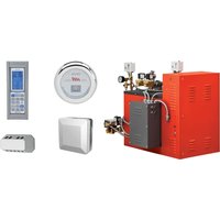
| Controls | Digital Control Center (DCC) with 24/7 programming, external user control |
| Operating Modes | MAX (maximum temperature), IDLE (energy saving), OFF (shut down) |
| Special Functions | Automatic drain in OFF mode, aromatherapy oil dispenser (optional pump), keypad lock |
| Safety | Safety valve, overheat protection (shut down if temperature exceeds setpoint by 10 °F), Cool Sense cover on steam head |
| Installation | Indoor only, upright and level position, max generator-to-head distance: 3 m (10 ft) without insulation |
| Maintenance | Automatic drain in OFF mode, generator flush, water supply purge |
| Commercial Warranty | 1 year parts and labor (90 days labor), electronic parts 2 years residential |
| Weight (estimated) | Approximately 30 kg (depending on configuration) |
| Dimensions (estimated) | 600 x 400 x 300 mm (L x D x H) |
Frequently Asked Questions - 5COM24-PAC DELTA
User questions about 5COM24-PAC DELTA
0 question about this device. Answer the ones you know or ask your own.
Ask a new question about this device
Download the instructions for your Shower system in PDF format for free! Find your manual 5COM24-PAC - DELTA and take your electronic device back in hand. On this page are published all the documents necessary for the use of your device. 5COM24-PAC by DELTA.
USER MANUAL 5COM24-PAC DELTA
see what Delta can do™
Model Number:
Número del modelo
Numéro de modèle
Serial Number:
Número del serie
Matricule
Date of Purchase:
Fecha de compra
Date d'achat
Register Online
Regístrese en línea
www.deltafaucet.com/service-parts/product-registration
To reference replacement parts and access additional technical documents and product info, visit www.deltafaucet.com/service-parts
www.deltafaucet.com/service-parts/contact-us/
Read all instructions prior to installation.
CAUTION
Failure to read these instructions prior to installation may result in personal injury, property damage, or product failure. Manufacturer assumes no responsibility for product failure due to improper installation.
SERVICE INTENSE 5COM(09-24)-PAC

natural_image
Technical line drawing of an industrial machine with hoses and control panel (no text or symbols)Important Safety Guidelines:
A) Do not permit children to use the steam bath unless they are closely supervised at all times.
B) Wet surfaces of the steam enclosures may be slippery. The floor should be skid resistant. Bathers should use care when entering and exiting the steam enclosure.
C) The steam head is hot. Bathers should not touch the steam head and should avoid contact with steam near the steam head.
D) Prolonged use of the steam bath can excessively raise the internal human body temperature and impair the body's ability to regulate its internal temperature (hyperthermia). Limit the use of steam to 10 – 15 minutes until you are certain of your body's reaction.
E) Excessive temperatures have a high potential for causing fetal damage during the early months of pregnancy. Pregnant or possibly pregnant women should consult a physician regarding correct exposure. Obese persons and persons with a history of heart disease, low or high blood pressure, circulatory system problems, or diabetes should consult a physician before using the steam bath.
F) Persons using medication should consult a physician before using a steam bath since some medication may induce drowsiness while other medications may affect heart rate, blood pressure and circulation.
G) The facility manager should fully understand the causes, symptoms, and effects of hyperthermia which may be described as follows: Hyper thermia occurs when the internal temperature of the body reaches a level several degrees above the normal body temperature of 98.6^ F. The symptoms of hyperthermia include an increase in the internal temperature of the body, dizziness, lethargy, drowsiness, and fainting. The effects of hyperthermia include:
- Failure to perceive heat.
- Failure to recognize the need to exit the steam bath.
- Physical inability to exit the steam bath.
- Unawareness of impending risk.
- Fetal damage in pregnant women.
- Unconsciousness.
WARNING
The use of alcohol, drugs, or medication can greatly increase the risk of hyperthermia.
H) The facility manager/owner is responsible for building and operating the steam room in a safe manner that is appropriate for the needs of their clientele. The facility manager/owner must be fully knowledgeable of all safety concerns and how to manage them. This includes but is not limited to the design of the steam room, the placement of the steam head, temperature settings and allowable usage times, and signage. The facility manager/owner must be familiar with all product safety warnings; instructions for operation; and all applicable codes, regulations, and ordinances. Additionally, there may be local government requirements regarding the operation of a steam room in your area. It is strongly recommended that the facility manager/owner seeks the assistance and advice of a professional plumber.
Warning Sign Installation:
The warning sign shown below and provided with the generator MUST be permanently installed on the steam room door or the wall immediately adjacent to the steam room.

WARNING
REDUCE THE RISK OF OVERHEATING AND SCALDING
- EXIT IMMEDIATELY IF UNCOMFORTABLE, DIZZY, OR SLEEPY. STAYING TOO LONG IN A HEATED AREA MAY CAUSE OVERHEATING.
- SUPERVISE CHILDREN AT ALL TIMES.
- CHECK WITH DOCTOR BEFORE USE IF PREGNANT, DIABETIC, IN POOR HEALTH, HAVE HIGH OR LOW BLOOD PRESSURE, HEART CONDITION OR UNDER MEDICAL CARE.
- BREATHING HEATED AIR IN CONJUNCTION WITH CONSUMPTION OF ALCOHOL, DRUGS, OR MEDICATION IS MAY CAUSE UNCONSCIOUSNESS.
- AVOID CONTACT WITH THE STEAM HEAD AND THE STEAM AT THE STEAM HEAD.
REDUCE THE RISK OF A SLIP AND FALL INJURY
- USE CARE WHEN ENTERING OR EXITING THE STEAM ROOM; FLOOR MAY BE SLIPPERY.
Figure 1 - Access Requirements
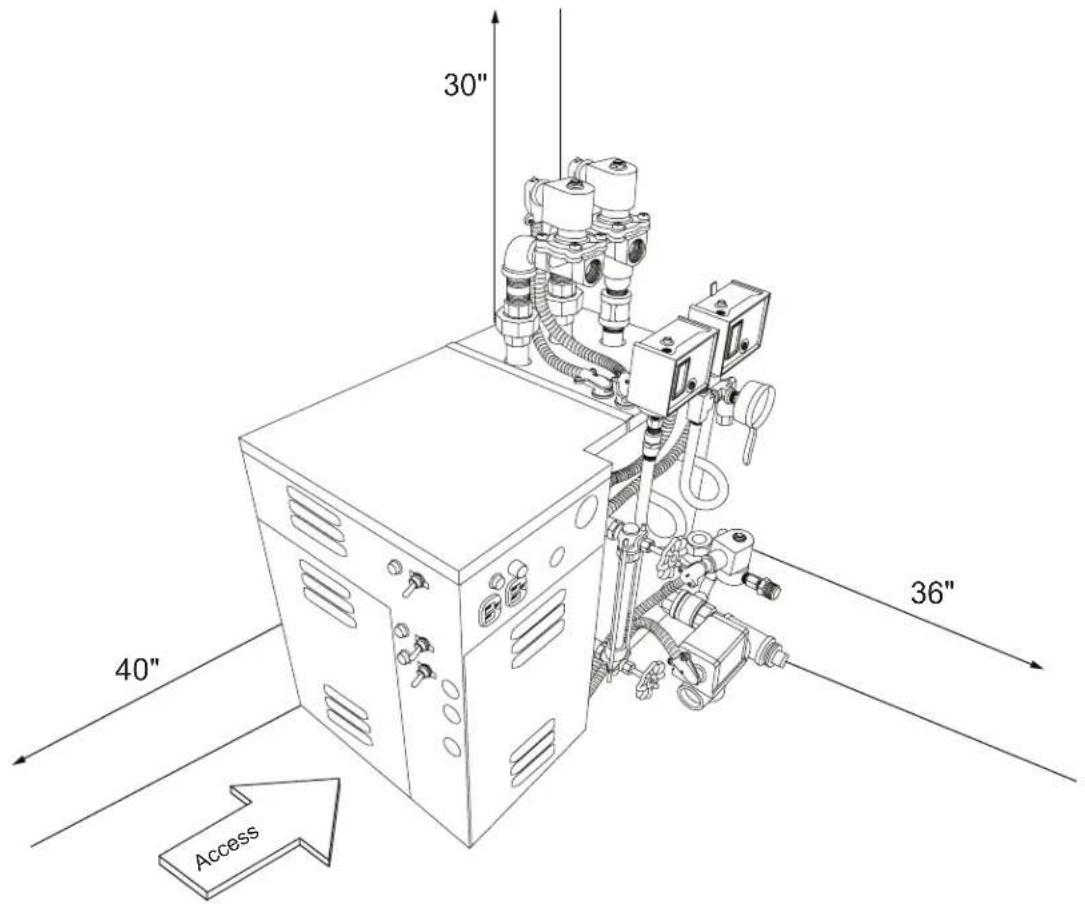
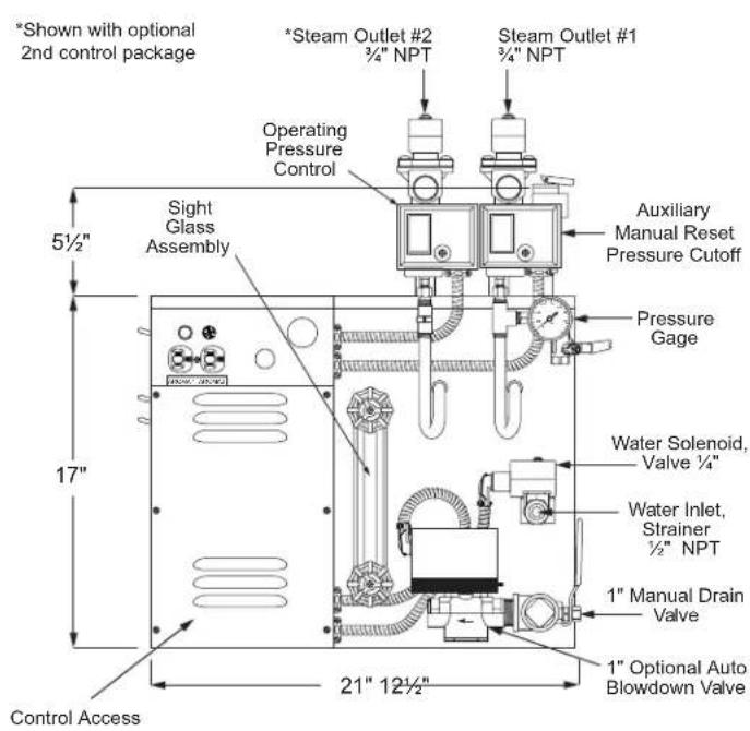
Figure 2 - Dimensional Drawing for Heavy Commercial Steam Generator

Pre-Installation Pre-Instalación Avant l'installation
IMPORTANT:
- All plumbing and electrical work must conform to local and national codes, regulations, and ordinances. Consultation with a professional plumber is strongly recommended.
- All power must be OFF to the steam generator unit when installing or servicing the unit.
- Only authorized components, accessories, or products should be used and/or installed on the generator and its piping.
Pre-Installation:
The following general information should be used in conjunction with your architect, designer and contractor in providing a suitable and safe steam room environment for the steam bathers.
IMPORTANT: Refer to the specification plate affixed to the cabinet of the steam bath generator.
A) Ensure that the model steam generator unit purchased is sized adequately for your steam room.
B) Be sure to have the proper electrical supply. Determine proper size of wire, voltage, amperage, and phase for the steam generator based on the specification plate attached to the generator and the chart in the back of this manual (see page 21).
C) Provide an inline fuse/circuit breaker as required sized in accordance with specification chart.
WARNING
Do not install a GFI Ground Fault Interrupter to this equipment.
D) Select a location to install the generator to allow sufficient room (See Access Area Requirements) for access to the unit in the event service is required. Select a clean dry indoor location protected from freezing. Do not store flammable materials such as gasoline, thinners, paints, etc. within 20 feet of the steam generator. Do not store corrosive materials such as chlorine within 20 feet of the steam generator.
E) Location of the steam generator should have an ambient temperature range within: 40°F to 104°F.
F) For safe low temperature draining (blow down) of the steam generator it may be necessary to drain into an ASME blow down tank. If required, additional space for the tank will be necessary. The blow down process can potentially dump boiling water down the drain and damage the drainage system. You should consult with your architect or a licensed plumber if you will require a blow down tank.
G) The steam generator should be located as close as possible to the steam room. If the steam generator is more than ten feet from the steam head, insulate the steam pipe with appropriate pipe insulation rated for a minimum of 250^ F.
H) The serial number plate should be visible after installation.
I) The steam room must be completely sealed on all sides, top and bottom. Floor, walls, and ceiling should be completely covered with waterproof material such as tile. Floor and bench materials must be slip resistant (see Safety Warnings on page 2).
J) Provide a floor drain inside the steam room for condensate run-off and steam room cleaning.
K) Only water tight lighting fixtures approved for the application should be used.
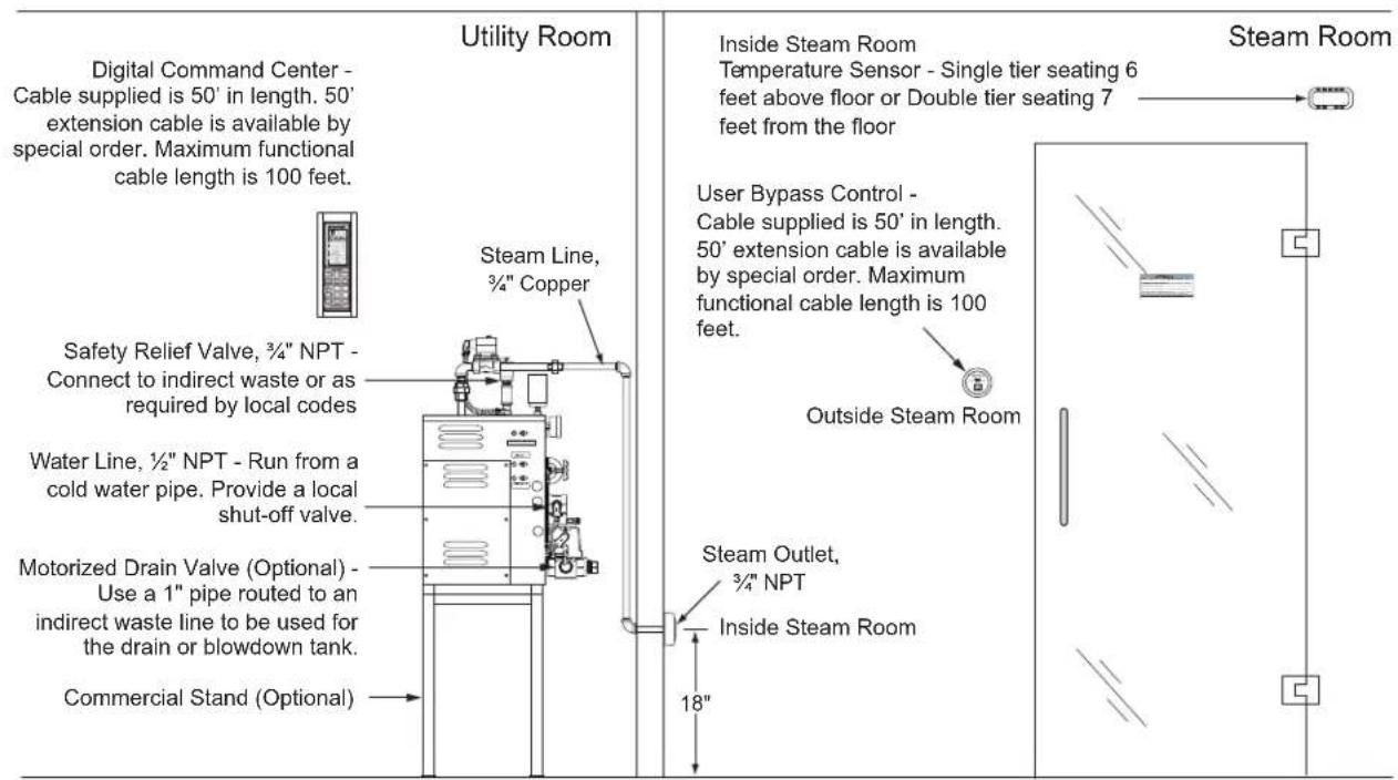
Figure 3 - Typical Steam Generator Installation
IMPORTANTE:
The 5COM(09-24)-PAC generator requires the following connections: 1/2" NPT piping for the water inlet, 3/4" copper tubing for each steam outlet, and 3/4" NPT safety valve should be piped to an indirect waste line. A 1" drain line for an optional auto blow down assembly must be piped to an indirect waste line.
IMPORTANT: The Optional Auto Blow Down feature can dump a few gallons of boiling water down the drain and potentially damage the plumbing. It may be necessary to drain into an ASME Blowdown Tank (Available as an option from Delta Faucet) depending on the requirements of plumbing system and local and national codes. Consultation with a professional plumber is strongly recommended.
1) Rough-in a 12 " water line from a cold water supply. Provide a local shut-off valve.
2) Rough-in the steam line using 3/4" copper tubing. Do NOT use iron or galvanized pipe, it will rust and discolor wall of steam room. For a steam line that is longer than 10 feet use an appropriate pipe insulation rated for a minimum of 250°F. The steam head should be located approximately 18" above the floor and as far from the bather as possible. Do NOT install shut-off valves in this line. Do NOT create traps or valleys in this line which would trap condensation and block the flow of steam.
3) Rough-in a 1" drain line for a manual drain or an optional auto blow down assembly and provide for an indirect waste line, to be used for draining steam generator. The indirect drain must be in accordance with local plumbing codes.
4) Rough-in a drain line using 34 " pipe routed to an indirect waste line from the Safety Relief valve. The discharge end of this pipe must NOT be restricted in any way. It must be piped in a way that would safely discharge steam and/or boiling water in the event of a failure. Always follow local plumbing and national codes.
Electrical Rough-in:
1) Route power supply cable to the location where the steam generator will be installed.
2) Route control cables as described in the Digital Command Center.
Digital Commercial Control Package rough-in:
The Digital Commercial Control Package (DCCP) is factory wired for either one or two steam rooms. The following installation instructions are typical for both room installations.
IMPORTANT: The command center cable, USER BYPASS CONTROL cable and sensor cable are not the same and must not be confused.
1) Digital Command Center (DCC) rough-in: Route the command center cable from the generator to the selected dry mounting location convenient to the facility operator.
IMPORTANT: the cable is 50' long. 100' cable is available by special order. Maximum functional cable length is 100 feet.
2) USER BYPASS CONTROL: Route the USER BYPASS CONTROL cable from the generator to the selected area outside of the steam room.
3) Room Temperature Sensor: Route the temperature sensor cable from the generator to the selected location inside the steam room. For sensor installation and location, see Figure 3. Make sure the generator end is located near the generator mounting location and the sensor end is located near the sensor mounting location.
IMPORTANT: the cable is 50' long. 50' extension cables are available by special order. Maximum functional cable length is 100 feet.
Tuberías internas:
Plumbing Installation: Care must be taken when installing the 5COM(09-24)-PAC generator. Leave proper access for servicing (See Installation Area Requirements). (Refer to Figure 3 for typical steam generator installation.)
CAUTION
Steam generator is designed to be used ONLY in an upright and level position; to do otherwise would damage the unit and void the warranty.
For convenient access mount the 5COM(09-24-PAC generator on the optional stand designed specifically for the 5COM(09-24)-PAC generator.
1) Water supply: Purge the water supply line before connecting to the steam generator. In areas where high water pressure may be a problem, a water hammer arrestor should be installed.
2) Steam line: Connect the steam line from the previously roughed-in location to the steam solenoid valve on the generator marked "steam outlet." If
the generator is equipped to provide steam to two rooms, care must be taken to make sure the proper steam solenoid is piped to the proper room.
3) Safety Line: Connect the 3/4" NPT safety valve into the previously installed indirect waste line.
4) Optional automatic blow down: Pipe into the 1" indirect waste line.
5) For steam head installation (see Page 23).
6) The steam, safety, and drain pipes become hot during operation and should be insulated with appropriate rated pipe insulation to protect against accidental contact.
Electrical Installation:
WARNING
ALL POWER TO THE STEAM GENERATOR MUST BE TURNED OFF.
1) Remove the top access cover to the electrical power compartment. (See Figure 4.)
2) Locate appropriate knockout and mount a proper strain relief into knockout hole.
3) Strip back the power cable's outer insulation jacket and insert into the box. Strip back insulation 3/4" from the incoming wires: single phase (two power and one ground). 3 phase (three power and one ground).
4) Insert ground wire into grounding lug.
CAUTION
Make sure ground wire does not come in contact with live electrical connections.
5) Locate power block and insert power wires into proper power lug terminals on top of the block and secure.
Aroma Pump Option: The aroma pump requires a separate 15 amp 120 volt branch circuit to be connected (see Figure 4). This is only necessary to run the aroma pump and is not needed if the pump is not used. To connect the power, remove the top cover of the generator. Select the knock out to route the 15 amp 120 volt line into the box. Connect the neutral, hot, and ground to the terminal block. Replace the cover. Plug in the pump into the appropriate receptacle depending on which room the pump is connected to.
NOTE: The pump will only pump when the appropriate room control is in the MAX mode, the ambient room temperature of that room is above the IDLE setting and the steam valve for that room is on. This feature reduces oil consumption by limiting the pumping to the max mode only. Maximum economy of oil consumption can be realized by programming the Digital Commercial Control Package (DCCP) to remain in idle mode throughout the day. If programmed this way the oil will only be dispensed when a steam bather presses the button on the user control outside the steam room switching the steam bath to MAX mode for a preset time defined by the manager (recommended setting is 10 minutes). Programmed this way, the oil is only pumped on the demand from the user and is a substantial cost savings (See Operating Instructions page 13).
Digital Command Center Installation:
WARNING
ALL POWER TO THE STEAM GENERATOR MUST BE TURNED OFF BEFORE PROCEEDING WITH INSTALLATION.
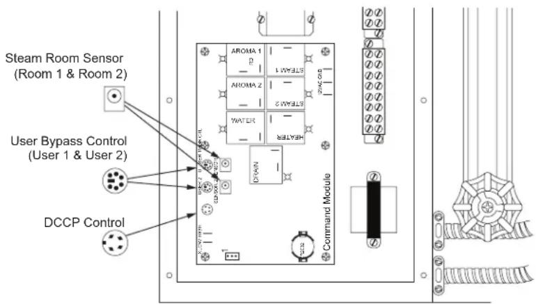
A) The DCCP comes factory wired for either one or two steam rooms. The following installation instructions are typical for both room installations. The configuration for one or two room is set at the factory. When the generator is configured for two rooms (SRP-Second Room Package must be ordered) it will have two room temperature sensors (one per room), two electric steam valves, two USER BYPASS CONTROLS, and two steam heads. The electric steam valves will be labeled 1 and 2. The connections for the sensors, USER BYPASS CONTROL(s), and aroma pumps, will all be labeled for room 1 and room 2. You must pay careful attention to not get the connection to room 1 and room 2 crossed. If the generator is configured for one room there will not be any special markings.
B) The USER BYPASS CONTROL should be located outside the steam room door convenient to the bather. This control gives the bather limited control of the steam room. The system will operate without this control but this function is lost. See the operating instructions for further information on this function. Route the USER BYPASS CONTROL wire from the selected mounting area to the control board in the steam generator (see Figure 6 and 7). The USER BYPASS CONTROL mounts to 2-1/8" or 55 mm round hole in the wall.
C) DIGITAL COMMAND CENTER (DCC) is intended to be used solely by the facility manager/owner. It should be located at a convenient height for programming. It may be mounted on the wall of the utility room near the steam generator, in the manager's office, or the front desk. The factory supplied wire is 50 feet long, therefore the generator must be located within its reach.
IMPORTANT: The DCC is unique and not to be confused with the USER BYPASS CONTROL wires or the sensor wires. The DCC uses a 4 wire connector, the USER BYPASS CONTROL uses a 6 wire connector and the room sensor uses a 2 wire connector. Route the DCC wire from the selected mounting location to the control board located in the steam generator (see Figure 6 and 7). The DCC mounts to a hole in the wall 2-1/2"w x 7-7/8"h.
D) Room Temperature Sensor(s): The room temperature sensor is required for operation. The sensor must be located in the steam room approximately six feet above the floor and never closer than one foot to the ceiling or the corner of the room. Route the cable from this location to the control module on the steam generator. The sensor mounts to a 5/8" hole in the wall (see Figure 5 for more detail).
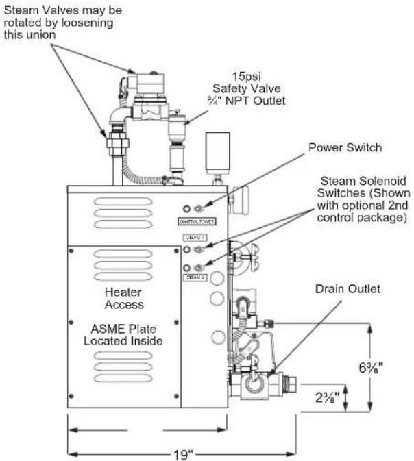
Figure 4 - Top of Generator
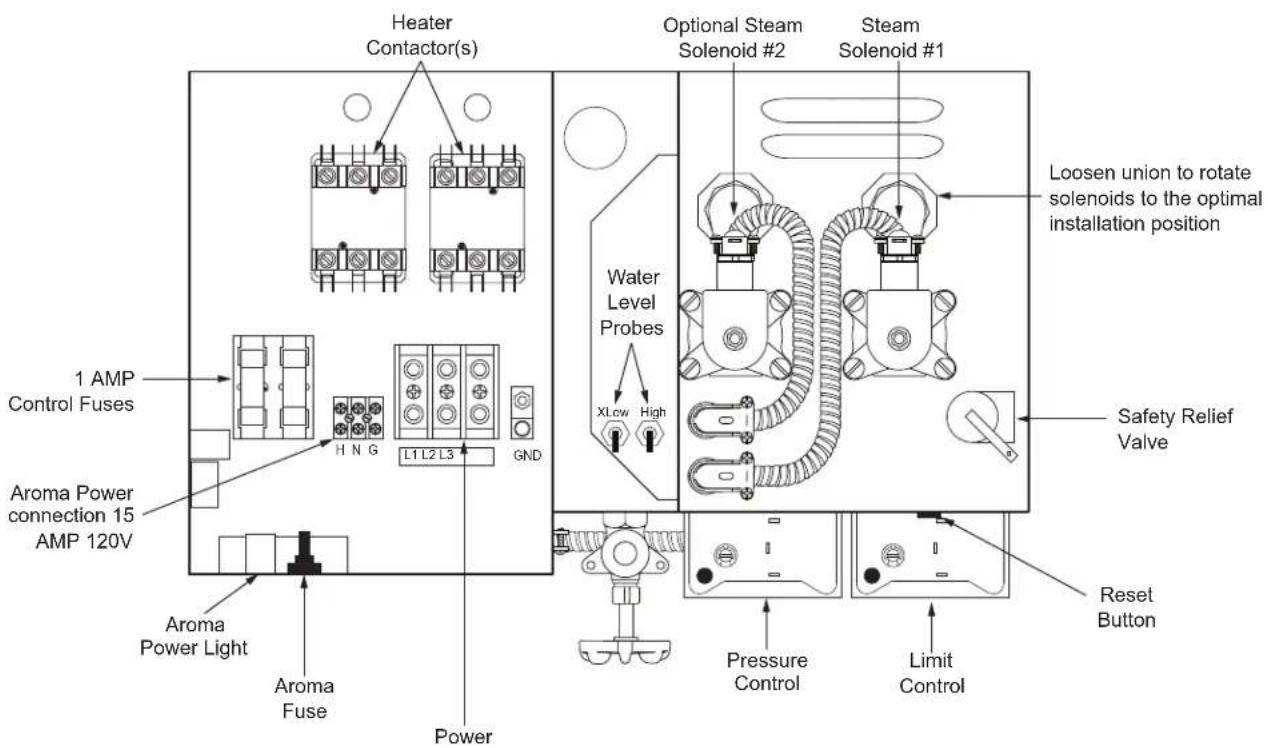
Figure 5 - Sensor Installation - Inside Steamroom
NOTE: Location of the sensor is as follows:
a) Single tier seating - 6 feet above floor.
b) Double tier seating - 7 feet above floor.
c) Place sensor on a wall adjacent or opposite of steam head. Do NOT place sensor above the steam head.
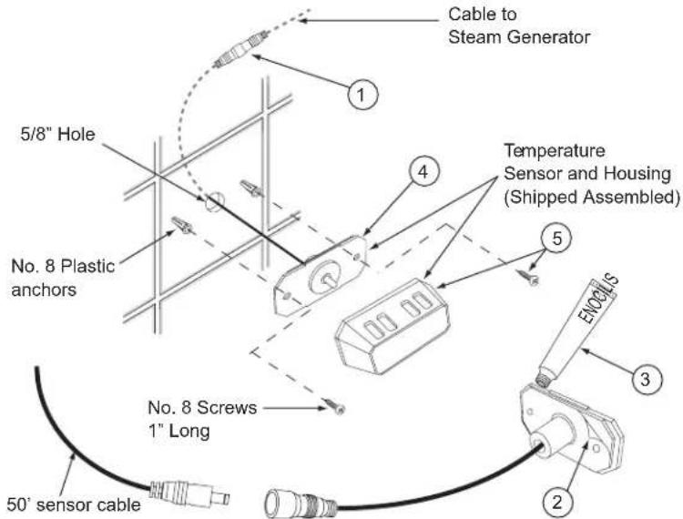
STEPS TO INSTALL SENSOR:
1) Take new sensor assembly and connect to 50' sensor cable. Please observe polarity of the 50' cable. Make sure the male end of the cable is routed toward the sensor in the steam room.
2) Peel off adhesive backing from sensor.
3) Carefully apply silicone sealant around rear edge.
4) Feed wires back into wall and press sensor firmly to wall (be careful to align plate holes with anchor holes).
5) Install screws, and snap chrome cover back into place.
6) Temperature sensor assembly must form a 100% water tight seal to the wall using silicone supplied.

INSTALACIÓN
This control is designed to maximize energy savings by allowing the facility manager/owner to set a lower operation temperature, called IDLE TEMP, and also to satisfy the steam bather with the ability to by-pass this feature on demand by pressing the USER BYPASS CONTROL button. Unlike a typical 24/7 timer, which has only an ON or OFF mode, the DCC has three modes: MAX, IDLE and OFF. MAX is the normal ON mode reserved for peak hours of use when the steam room is held at the optimum steam bath temperature. IDLE mode is the energy saving mode. IDLE is set below the MAX temperature and provides a significant energy savings. As needed, the steam bather can easily switch to the MAX setting by pressing the button on the USER BYPASS CONTROL.
USER BYPASS CONTROL: The USER BYPASS CONTROL button is only functional during the IDLE mode. To switch from IDLE mode to MAX mode, the steam bather must press the button on the USER BYPASS CONTROL. IDLE mode is indicated on the USER BYPASS CONTROL by one lit bar. Pressing the USER BYPASS CONTROL button starts the MAX CYCLE TIMER and immediately begins to heat the room to the MAX setting. This temporary MAX CYCLE TIMER is programmable up to 60 minutes by the facility manager. MAX TEMP mode is indicated by all bars lit. When the DCC is set to MAX TEMP, the USER BYPASS CONTROL icon displays max (all bars lit). In the MAX TEMP mode the USER BYPASS CONTROL buttons do not function. When the DCC is in the OFF mode the USER BYPASS CONTROL icon will be off (no bars lit) and the user buttons do not function.
Programming the DCC can be broken down into 3 separate sections, SET EVENT, SET VALUE, and SET CLOCK. The buttons on the control are grouped accordingly. SET EVENT is used to set the time and day that a particular mode (MAX, IDLE, or OFF) is to begin. SET VALUE is intended to set the MAX and IDLE temperature, as well as the MAX CYCLE TIMER. The SET CLOCK section is only for adjustment of the current time and day. The DCC display light comes on when any button is pressed. The light will remain on for 5 minutes after the last button is pressed.
1) SET CLOCK: The SET CLOCK section of the DCC is used exclusively for setting the current time and day. It is a convenient place to make changes for daylight savings time without having to reprogram other settings. The clock has a battery backup in the Control Module that will keep time for up to one year with no power.
(a) DAY setting: Press the lower DAY button to toggle the current day of the week.
(b) HOUR setting: Press the lower HOUR button to select the current AM or PM hour and the correct hour will be displayed.
(c) MINUTE setting: Press the lower MINUTE button until the correct minute is displayed.
2) SET VALUE: The SET VALUE section of the keypad is used to program the following 4 parameters:
(a) MAX1 TEMP is used to set the maximum desired operating temperature of the steam bath. It is set by pressing the button until the preferred maximum temperature is displayed. Note: The MAX TEMP cannot be set lower than the IDLE TEMP. Selection of the MAX TEMP setting is at the discretion of the facility manager.
(b) MAX2 TEMP (only available with SRP) is used to set the desired operating temperature of a second steam room. It is programmed the same as MAX1 TEMP.
(c) IDLE TEMP is used to program a lower temperature setting during periods of less frequent usage. It is set by pressing the button until the desired set-back temperature is displayed. The feature can be disabled by setting it to 00. The IDLE TEMP cannot be set higher than the lowest MAX TEMP value.
(d) MAX CYCLE TIMER is used to set the duration that the system will be in MAX TEMP mode after the USER BYPASS CONTROL button is pressed in. It is set by pressing the corresponding button on the DCC. Each time the button is pressed the minutes will increase in one minute increments from ":00" to ":60". If the MAX CYCLE TIMER is programmed to ":00", this feature will be disabled and the USER BYPASS CONTROL(S) will be disabled.
(e) Degree °C or °F change is made by placing a jumper over the CN112 pins for °C or by removing it for °F (jumper not included). The power must be OFF when making this change. (See Command Module on Wiring Diagram page 22).
3) SET EVENT: Before programming the SET EVENT, it is necessary to determine the hours the steam bath will operate and in which mode. Each day of the week can have up to six events programmed. The chart on the following page will help organize your plan for the SET EVENT function. The top 2 sections of the chart are filled in with 2 examples.
NOTE: Program #1 is set to 12:00am by default. This time cannot be altered. You can however set 12:00am to: OFF, IDLE, or MAX.
4) Programming SET EVENT: To program the SET EVENT section, first press the PROG# button on the Digital Command Center. The display will flash the current program number and show the start time of that program. The program can only be changed while flashing. To enter a new program, first press the DAY button in the upper SET EVENT section to choose the individual day or a block of days (i.e. M-TU-W-TH-F, or SU-M-TU-W-TH-F-SA). With the proper day(s) selected, press the MAX/IDLE/OFF button to choose the mode for Program 1.
NOTE: The time for Program 1 is factory fixed to 12:00AM. If the steam bath is to start at a later time, Program 1 must be set to OFF.
Program 1 is complete. Press PROG# button to get to Program 2. Enter the start time of Program 2 and select the mode. You are only programming the start time of each program. The end time is automatically the start time of the next program. The last program entered is limited to 11:59PM. If the facility operates beyond midnight, Program 1 of the next day must be set to 12:00AM for continuous operation. Follow the same process for all the programs and days of the week. To exit the programming mode, press the ENTER button or wait 30 seconds and it will stop blinking and your changes will be saved.
NOTE: Programs 1 through 6 are sequential and therefore it will not be possible to set a new program before the end of the previous program.
(a) Programming Tip: To modify an existing program press the PROG# button and the upper DAY button to get to highlight the program you want to change. Then modify the setting with the appropriate button. Entries will be saved automatically in 30 seconds or by pressing the enter button.
(b) Programming Tip: If the facility operates on nearly the same schedule every day, it may be easier to program all seven days to the same common program and then go back and program Sunday to be OFF if the facility is closed that day.
(c) Programming Tip: You can review your program by pressing the PROG# button and toggling through the programs and toggling through the days of the weeks, and observing the time settings. If you made no changes simply press the enter button to return to normal or it will return in 30 seconds.
(d) Programming Tip: When reviewing the program and a block of days are selected, if all the individual programs for those days do not match, the clock will display --:--. This is normal and any adjustments made at this time will reprogram all days selected to match the new entry.
5) Manager lock function: The DCCP has a locking feature that prevents any setting from being changed when locked. To lock the control, press the lock button; the lock icon will flash for up to 30 seconds. While the icon is flashing, press any three consecutive buttons, and then press the lock button again to confirm. The three consecutive buttons pressed are the password. The system control will be locked and the lock icon will be on steady. To unlock, press the lock button and then press the same three consecutive buttons as the previous password; the system will be unlocked and the lock icon will disappear. If the password is lost or forgotten, it can be reset. This will require two people. Turn off the main power (circuit breaker), have a second person then press and hold the lock button on the DCCP while the first person turns the power back on. The system will be unlocked. Also see the reset section for an alternate method (step 11).
6) Temporary Mode setting: By pressing IDLE/MAX/OFF button on the DCCP you can temporarily change the current mode (IDLE/MAX/OFF). This is only a temporary change until the next programmed event.
7) Auto-Blow Down: The optional auto-blow down becomes active in the OFF mode. When first entering OFF mode, the steam valves will deactivate and the generator will continue to maintain normal pressure. After 5 minutes the generator will shut down and the drain will open. Boiling water will exit under pressure and the water valve will turn on to help flush the generator. After 2 minutes the drain will close and the generator will refill. After a total of 7 minutes the generator is ready to start a new cycle. If the facility is operated 24 hours a day, a 7 minute OFF mode should be programmed in to allow for a proper drain cycle. In areas where the water is hard, a second drain cycle can be programmed by adding an extra 7 minute off mode program.
IMPORTANT: Due to possible code violations or damage to the building drainage system, the hot boiling water exiting in this process may require a Blow-Down Tank. Consult with your licensed contractor. Blow-Down tanks may be purchased separately.
8) Steam Control: The steam valve(s) are controlled according to the room temperature sensor(s) and the programmed mode. When the room temperature is lower than the set temperature by one degree the steam valve will turn on. When it reaches the set temperature it turns off. If for some reason the room temperature exceeds the MAX TEMP setting (of either room) by more than 10^ the DCCP will turn off the generator until that room temperature drops to 1^ below the set temperature.
9) Aroma Control: There are two aroma control relays (one for each room) located in the Command Module on the generator. These relays can be used with most aroma pumps available. The relays are programmed to conserve aroma therapy oil. The relays are only on when the following conditions are met: 1) The program for that room must be in the MAX mode. 2) The steam valve for that room must be on and the temperature in that room must be above the IDLE setting. When all these conditions are met, the aroma relays will energize.
10) Fahrenheit and Celsius: The Fahrenheit or Celsius temperature can be selected by changing a jumper in the Command Module (CN112). When it is not connected (open circuit), it will be Fahrenheit. When it is connected, it will be Celsius. The jumper must be switched with power off (see wiring diagram on page 22).
11) Reset Feature: If it is ever necessary to reset all the programs and start over press and hold the PROG# button and the lower MIN button for five seconds simultaneously. This will reset every setting in the DCCP. This process can also be used to unlock the control if the password is lost or forgotten.
Figure 6 - Cables

User bypass control cable (6-pin connector)
Figure 7 - Circuit Board Connections
EXAMPLE 1 Shows the facility opening at 8AM, due to less traffic during the first few hours, the mode is set at IDLE. Then at 10AM, the traffic increases; program switches to MAX. At 3PM, the traffic decreases; program switches to IDLE. Then at 7PM, the traffic increases; program switches to MAX. At 10PM, the facility closes; program switches OFF.
| PROG # 1 2 | 3 | 4 | 5 | 6 | |||
| TIME 12:00AM 8:00AM 10:00AM 3:00PM 7:00PM 10:00PM | |||||||
| EXAMPLE 1 | MAX | X | X | ||||
| IDLE | X | X | |||||
| OFF X | X | ||||||
EXAMPLE 2 shows the facility opening a 8AM and set to IDLE all day until 10PM when the club closes. This would yield maximum energy savings and is the recommended program. At any time the system is in IDLE mode the user can activate the MAX TEMP mode by pressing the USER BYPASS CONTROL button. Photo copy the chart and use it as a worksheet to plan your settings:
NOTE: If the steam room is open 24 hours a day you may set Program #1 to MAX or IDLE and do not need to set an OFF value unless you are turning it off to drain the system.
| PROG # 1 2 | 3 | 4 | 5 | 6 | |||
| TIME 12:00AM 8:00AM | 10:00PM | ||||||
| EXAMPLE 2 | MAX | ||||||
| IDLE | X | ||||||
| OFF | X | X | |||||
| PROG # | 1 | 2 | 3 | 4 | 5 | 6 | |
| TIME | |||||||
| SU | MAX | ||||||
| IDLE | |||||||
| OFF | |||||||
| TIME | |||||||
| MO | MAX | ||||||
| IDLE | |||||||
| OFF | |||||||
| TIME | |||||||
| TU | MAX | ||||||
| IDLE | |||||||
| OFF | |||||||
| TIME | |||||||
| WE | MAX | ||||||
| IDLE | |||||||
| OFF | |||||||
| TIME | |||||||
| TH | MAX | ||||||
| IDLE | |||||||
| OFF | |||||||
| TIME | |||||||
| FR | MAX | ||||||
| IDLE | |||||||
| OFF | |||||||
| TIME | |||||||
| SA | MAX | ||||||
| IDLE | |||||||
| OFF | |||||||
Specifications Chart
| Model No. | KW | Max. Cu. Ft. | Volts/ Phase/ Amps | Line Fuse | Water Inlet | Steam Outlet | Dimensions | Shipping Weight |
| 5COM09-PAC-609-240-01 | 9 | 400 | 240/1/38 | 50 | 1/2" NPT | 3/4" NPT | 21"x19"x25" | 140 lbs. |
| 5COM09-PAC-609-208-01 | 208/1/43 | 60 | ||||||
| 5COM09-PAC-609-240-03 | 240/3/22 | 30 | ||||||
| 5COM09-PAC-609-208-03 | 208/3/25 | 35 | ||||||
| 5COM09-PAC-612-240-01 | 12 | 500 | 240/1/50 | 70 | 1/2" NPT | 3/4" NPT | 21"x19"x25" | 150 lbs. |
| 5COM09-PAC-612-208-01 | 208/1/58 | 80 | ||||||
| 5COM09-PAC-612-208-03 | 208/3/33 | 45 | ||||||
| 5COM09-PAC-612-480-03 | 480/3/15 | 20 | ||||||
| 5COM09-PAC-615-240-01 | 15 | 620 | 240/1/63 | 80 | 1/2" NPT | 3/4" NPT | 21"x19"x25" | 150 lbs. |
| 5COM09-PAC-615-208-01 | 208/1/72 | 90 | ||||||
| 5COM09-PAC-615-208-03 | 208/3/42 | 60 | ||||||
| 5COM09-PAC-615-480-03 | 480/3/18 | 25 | ||||||
| 5COM09-PAC-618-240-01 | 18 | 740 | 240/1/75 | 100 | 1/2" NPT | 3/4" NPT | 21"x19"x25" | 150 lbs. |
| 5COM09-PAC-618-240-03 | 240/3/43 | 60 | ||||||
| 5COM09-PAC-618-208-03 | 208/3/50 | 70 | ||||||
| 5COM09-PAC-618-480-03 | 480/3/22 | 30 | ||||||
| 5COM09-PAC-624-240-01 | 24 | 1000 | 240/1/100 | 125 | 1/2" NPT | 3/4" NPT | 21"x19"x25" | 150 lbs. |
| 5COM09-PAC-624-208-01 | 208/1/115 | 150 | ||||||
| 5COM09-PAC-624-240-03 | 240/3/58 | 80 | ||||||
| 5COM09-PAC-624-208-03 | 208/3/67 | 90 | ||||||
| 5COM09-PAC-624-480-03 | 480/3/29 | 40 |
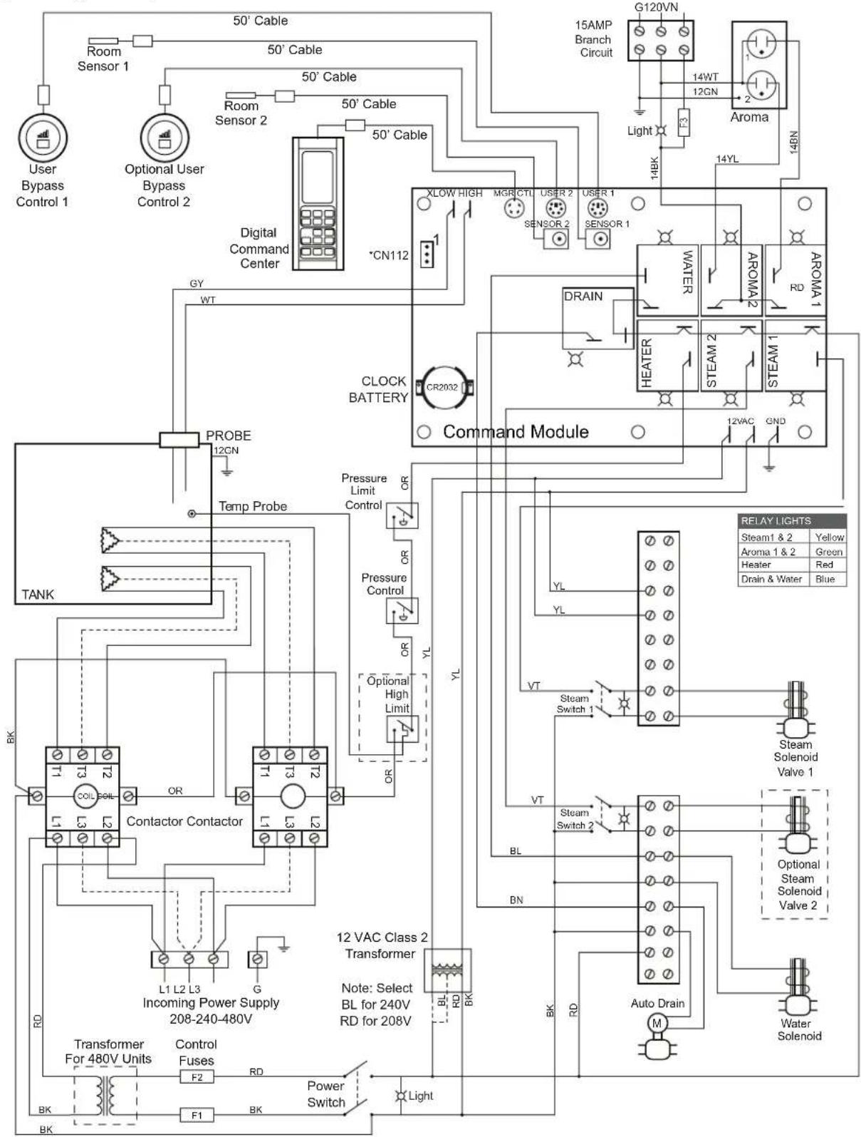
Figure 9 - Wiring Diagram with Options
Note: All factory wires are 18AWG unless otherwise noted. Power and heater wire gauge are set by the factory.
*Note: CN112 Jumper open: F° Jumper 2 to 3: C° Turn off power to make this change reset.
4
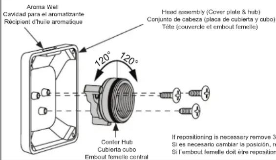
Steamhead Installation Instructions Instrucciones para la instalación del cabezal de vapor Instructions d'installation de la tête de vapeur
NOTE: The steam head has been designed with a 360° dispersion of steam to improve circulation and to minimize the hotspots created with the traditional steam heads. For maximum comfort the steam head should always be located as far from the seating area as possible. Should the location of the steam head necessitate blocking the steam from a particular direction to improve bather comfort, the supplied deflector plate can be added to any of the three sides shown to help divert the steam away from the bather. The deflector is attached to the back side of the head before installation with 2 stainless steel screws provided.
- Make sure the 3/4" nipple protrudes beyond the tile 1/4" to 1/2".
IMPORTANT: If the nipple protrudes beyond 1/2", the O-ring will not make a proper seal and the nipple will have be adjusted. - Wrap the threads of the nipple with pipe sealant tape.
- Make sure the head will line up in the upright position when tightened. The head should only be firmly hand tightened. Using a wrench on the head may damage it. Screw the head onto the nipple and see how it lines up. Once a proper alignment is made remove the head.
NOTE: If necessary the head can be repositioned by disassembling the hub from the cover and selecting one of the two alternate positions as shown in figure 1. - Re-apply sealant tape if necessary.
- Place a bead of silicone around the pipe, sealing the pipe to the wall.
- Place a bead of silicone around the back outer edge of the back plate.
NOTE: Follow silicone manufacturer's instructions for dry/cure time.
- Center and square the back plate over the nipple. While holding it in place, screw the head onto the nipple, hand tighten.
- Adjust the back plate and head to line up squarely. Remove any excess silicone with rubbing alcohol.
- The included silicone Cool Sense Cover should be placed over the steam head. Secure it permanently to the steam head with clear silicone.
CAUTION
The steam head is 212^ during operation and will cause a contact burn if touched. The steam head must be located in an area that will avoid likely contact. Permanently installing the silicone cover (see Figure 11) can help reduce the likelihood of a contact burn from the steam head.
Figure 10
Limited Warranty on Delta® Steam Bath and Steam Shower Products Applicable to products purchased and installed in the USA and Canada
Residential Steam Bath Generators: Delta Faucet Company ("DFC") warrants to the original consumer purchaser that the parts (except for electronic parts) of its residential steam bath generator purchased from authorized Delta sellers will be free from defects in materials and workmanship for as long as the original consumer purchaser owns the home in which the steam bath was originally installed. This lifetime limited warranty does not apply to residential steam bath generators that are used in commercial applications (as defined herein).
Residential Electronic Parts, Controls, Spa Options and Accessories: DFC warrants to the original consumer purchaser that the electronic parts of its steam bath generator and its controls, spa options and accessories purchased from authorized Delta sellers will be free from defects in materials and workmanship for a period of two (2) years from the date that the product is received by the original consumer purchaser or their authorized representative (installation contractor, etc.). This two-year limited warranty does not apply to controls, spa options, electronic parts and accessories that are used in commercial applications (as defined herein).
Commercial Warranty: For the purposes of this warranty the term "commercial application" refers to installation in any setting in which the product is not being used for personal household use, including but not limited to hospitality applications, day spas, short-term and long-term rentals and gyms.
DFC warrants that the parts (including electronic parts) of its steam bath generators (including steam bath generators with model numbers beginning with 5COM, which are intended solely for heavy commercial use), equipment, controls, electronic parts, spa options and accessories purchased from authorized Delta sellers and used in a commercial application will be free from defects in materials and workmanship for a period of one (1) year from the date that the product is received by the original purchaser or their authorized representative (installation contractor, etc.).
What We Will Do: DFC will, at its option, repair or replace, free of charge, any part that proves defective in material and/or workmanship under normal installation, use and service during the applicable warranty period as stated above. DFC may elect to refund the purchase price. Replacement parts are subject to availability and may differ from those originally supplied.
For residential applications, two (2) years following the date that the product was received by the original consumer purchaser or their authorized representative (installation contractor, etc.), and with prior approval by DFC, DFC will pay for labor for repair/replacement associated with warranty coverage. Thereafter, DFC will not pay for labor associated with removal/repair/replacement of products covered by this warranty.
For commercial applications, DFC will, with prior approval by DFC, pay for labor associated with warranty coverage for ninety (90) days from the date that the product is received by the original purchaser or their authorized representative (installation contractor, etc.). Thereafter, DFC will not pay for labor associated with removal/repair/replacement of products covered by this warranty. These are the consumer's exclusive remedies.
What Is Not Covered: Because DFC is unable to control the quality of Delta products sold by unauthorized sellers, unless otherwise prohibited by law, this warranty does not cover Delta products purchased from unauthorized sellers. This warranty does not cover damage caused by improper or negligent installation or use. Provided that DFC is paying
the cost of the labor under the terms above, this warranty does not cover repairs attempted by any person other than an authorized DFC agent and shall be limited to the repair or replacement of defective parts by DFC or its authorized agent. This warranty is void if any of the following should occur:
- The use of the product for an unintended application, including the commercial application of a product that is not intended for commercial use.
- Failure to follow instructions, including care, cleaning and usage instructions, provided in the product's owner's manual.
• The product's serial number has been altered or removed.
- The product is modified in any manner which DFC concludes, after its inspection, affects the reliability of the product. - The product has been improperly repaired by anyone not specifically designated or authorized by DFC.
• The product is damaged because it is not operated or installed in accordance with supplied instructions.
• The product is installed outdoors.
• The product is installed in a moist and/or humid area with unconditioned air or temperatures that exceed 104 degrees Fahrenheit.
• The product is damaged due to freezing
• The product is damaged by acts of God.
How to Make a Warranty Claim: To obtain warranty repair or replacement, contact DFC at: 800-394-6478 or steam-prodserv@dellafaucel.com to receive an RGA# (Return Goods Authorization number) which must be on the carton that is returned via UPS Ground or equivalent. Proof of purchase (original sales receipt showing purchase date) identifying the model and serial number and documentation of the date of receipt of the product by the original purchaser or their authorized representative (installation contractor, etc.) must accompany all warranty claims.
Limitation on Duration of Implied Warranties: Please note that some states/provinces (including Quebec) do not allow limitations on how long an implied warranty lasts, so the below limitations may not apply to you. TO THE MAXIMUM EXTENT PERMITTED BY APPLICABLE LAW, ANY IMPLIED WARRANTY, INCLUDING THE IMPLIED WARRANTIES OF MERCHANTABILITY AND OF FITNESS FOR A PARTICULAR PURPOSE, IS LIMITED TO THE STATUTORY PERIOD OR THE DURATION OF THIS WARRANTY. WHICHEVER IS SHORTER.
Limitation of Special, Incidental or Consequential Damages: Please note that some states/provinces (including Quebec) do not allow the exclusion or limitation of special, incidental or consequential damages, so the below limitations and exclusions may not apply to you. TO THE MAXIMUM EXTENT PERMITTED BY APPLICABLE LAW, THIS WARRANTY DOES NOT COVER, AND DFC SHALL NOT BE LIABLE FOR, ANY SPECIAL, INCIDENTAL OR CONSEQUENTIAL DAMAGES WHETHER ARISING OUT OF BREACH OF ANY EXPRESS OR IMPLIED WARRANTY, BREACH OF CONTRACT, TORT, OR OTHERWISE.
Additional Rights: This warranty gives you specific legal rights, and you may also have other rights which vary from state/province to state/province. This is DFC's exclusive written warranty and the warranty is not transferable.


- see what Delta can do™
- CAUTION
- Important Safety Guidelines:
- WARNING
- Warning Sign Installation:
- REDUCE THE RISK OF OVERHEATING AND SCALDING
- REDUCE THE RISK OF A SLIP AND FALL INJURY
- Pre-Installation Pre-Instalación Avant l'installation
- IMPORTANT:
- Pre-Installation:
- IMPORTANTE:
- Electrical Rough-in:
- Digital Commercial Control Package rough-in:
- Tuberías internas:
- Electrical Installation:
- Digital Command Center Installation:
- Figure 5 - Sensor Installation - Inside Steamroom
- STEPS TO INSTALL SENSOR:
- INSTALACIÓN
- 4
- Steamhead Installation Instructions Instrucciones para la instalación del cabezal de vapor Instructions d'installation de la tête de vapeur
- Limited Warranty on Delta® Steam Bath and Steam Shower Products Applicable to products purchased and installed in the USA and Canada
Brand : DELTA
Model : 5COM24-PAC
Category : Shower system