
1600T9001RI - Electronic urinal DELTA - Free user manual and instructions
Find the device manual for free 1600T9001RI DELTA in PDF.

| Product Type | Touchless Electronic Urinal |
| Brand | Delta (Commercial Line) |
| Model | 1600T9001RI |
| Power Configuration | Rear or top connection (depending on sub-model) |
| Cover Plate Dimensions | 254 x 254 mm (10 x 10 in) |
| Control Box Dimensions | 203 x 206 x 102 mm (8 x 8-1/8 x 4 in) |
| Weight | Not specified in the manual (estimated ~2 kg) |
| Power Supply | 24 V AC transformer, Class 2 (not included) |
| Power Consumption | 24 V AC, 1 A (min. wire 18 AWG) |
| Sensor | Infrared detector with confirmation light |
| Detection Distance | Adjustable from 30.5 to 71.1 cm (12 to 28 in) in increments |
| Flush Delay | No delay (immediate flush after removal) |
| Default Flush Volume | 0.5 GPF (1.9 LPF) |
| Adjustable Flush Time | 3.2 to 7.8 seconds (preset at 3.6 s) |
| 24-Hour Flush | Can be enabled/disabled (disabled by default) |
| Override Button | Yes, for manual flush |
| Plate Material | Stainless steel |
| Water Inlet | 1/2 in (13 mm) copper |
| Outlet | 3/8 in MIP (for urinal connection) |
| Operating Temperature | Not specified (standard indoor use) |
| Compliance | FCC Part 15 Class A, CAN ICES-3 (A) / NMB-3(A) |
| Warranty | 5 years (parts and finish, labor excluded) |
| Spare Parts | List provided: transformer, solenoid valve, sensor, etc. |
| Cleaning and Maintenance | Clean the plate with a soft cloth; follow installation instructions |
Frequently Asked Questions - 1600T9001RI DELTA
User questions about 1600T9001RI DELTA
0 question about this device. Answer the ones you know or ask your own.
Ask a new question about this device
Download the instructions for your Electronic urinal in PDF format for free! Find your manual 1600T9001RI - DELTA and take your electronic device back in hand. On this page are published all the documents necessary for the use of your device. 1600T9001RI by DELTA.
USER MANUAL 1600T9001RI DELTA
Commercial - Electronic Washdown Urinal (with H₂Optics®)
TR - Trim
RI - Rough-in
OPTION D'ALIMENTATION
TR - De garniture
RI - De robinetterie brute
natural_image
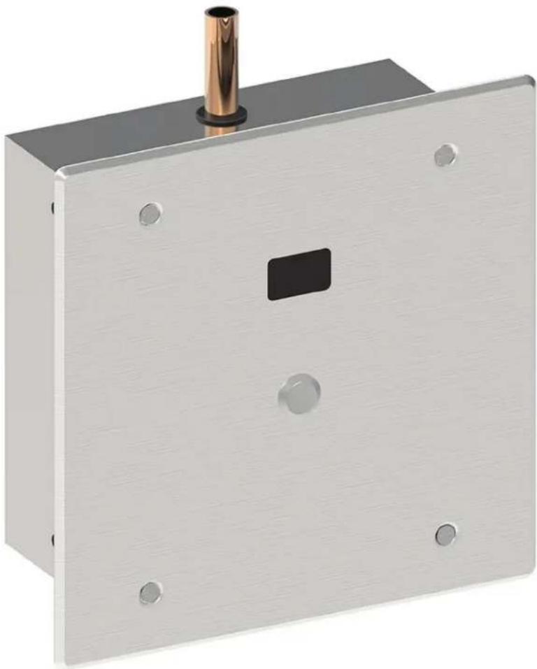
Metallic electrical switch or panel with a cylindrical top and square button, no visible text or symbolsWARNING Models with plain outlet must be installed on a urinal fixture providing sufficient air gap protection against backflow.
NOTICE Product supplied as shown by solid lines. All items shown by dotted lines supplied by others.
WARNING Models with plain outlet must be installed on a urinal fixture providing sufficient air gap protection against backflow.
- 8" (20.3 cm) box is supplied, remove suitable knockout (2) and insert cable bushing (1) (see figure 1).
- Rough-in box flush to the wall, so the valve will be positioned on centerline of fixture (see figure 2).
- Securely attach box to wall structure.
- Install CSA and/or UL approved Class 2 24VAC transformer or equivalent (not provided - optional repair parts 060704A or 060771A) in a convenient location or in a pipe chase.
WARNING DO NOT install the transformer inside this rough-in box.
- Run wire from the 24VAC power source to the rough-in box.
NOTICE Wire must comply with local electrical codes for 24VAC, 1 amp load (Min. 18 AWG wire is usually sufficient).
-
Connect water supply to 1/2" (13 mm) copper inlet.
-
Connect rough-in outlet to urinal fixture.
STEP 2. SYSTEM FLUSH (see Figure 3)
- Open screwdriver stop (1) to flush installation for 1 minute minimum.
- Check for leaks.
- Close stop (1).
⚠️ CAUTION DO NOT over torque stop (1).
ÉTAPE 2. RINÇAGE DU SYSTÈME (voir Figure 3)
- Replace the spacer (2) with the slow closing solenoid valve (3).
- Open screwdriver stop (1).
- Check for leaks at solenoid.
NOTICE
- Solenoid may be rotated for installation of cover assembly.
- Flow direction ARROW (4) on bottom of the solenoid.
ÉTAPE 3. ÉTAPE 3 - INSTALLATION DE LA VANNE SOLÉNOÏDE (VOIR FIGURE 3)
WARNING Models with plain outlet must be installed on a urinal fixture providing sufficient air gap protection against backflow.
- Ensure the push button (3) is connected to the sensor (2a) using the spade connectors (2a).
- Connect the spade connectors (2c) from the sensor module (2) to the solenoid (5) in the rough-in box of the flush valve.
NOTICE Ensure the red wire (2c) is connected to the positive (+) tab which is marked on the solenoid coil.
- Attach hardwire converter (1) to the sensor module (2) using the snap connectors (1b & 2b).
- Attach hardwire converter (1) using suitable wire from 24VAC power source into box connecting to wires (1a) with wire nuts provided.
NOTICE
- Use wire that complies with local electrical codes for 1 amp load.
- With power supplied to the flushometer, there will be a sequence of red lights that strobe across the sensing lens window which signifies that the valve is now in operation mode.
Factory pre-set functions are: Washdown urinal sensing distance of 20" (50.8 cm), 24 hour flush is off, no flush delay and flush volume is 0.5 gpf (1.9 Lpf).
- Purge system and check for leaks.
- If adjustments to the factory pre-sets are desired, see "Step 5. MAKING ADJUSTMENTS (see Figure 6)" on page 6 for further instructions.
NOTICE No adjustment to flush delay
- Attach sensor plate (4) to the rough-in box (6) using the 4 vandal proof screws (7) provided.
Figure 5
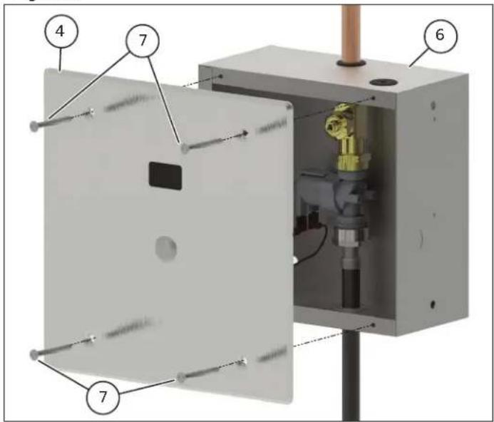
Figure 6
STEP 5. MAKING ADJUSTMENTS (see Figure 6)
(Optional: Only required if factory settings are not preferred)
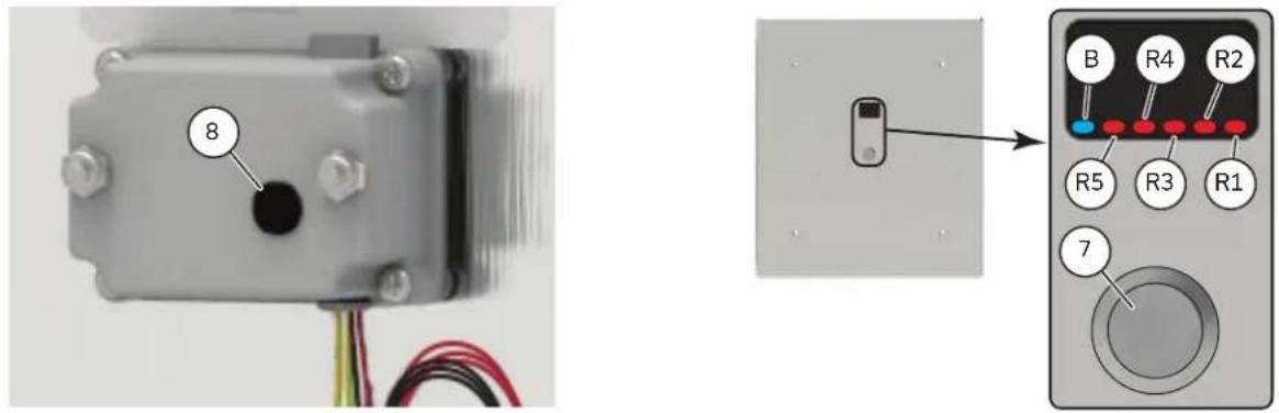
To move from operation mode into set-up mode: remove the plastic plug (8) located in the rear of the sensor module and press the set-up mode button once. A pencil or small screwdriver may be required. A sequences of red lights (R1 to R5) will strobe across the sensor window, followed by a 3 steady red lights (R1 to R3)(factory default). Replace the plug back in the hole.
ADJUSTING SENSING DISTANCES:
- Referencing the Pre-Set Sensing Distances table, the number of steady red lights (R1 to R5) identifies the current setting.
- The flashing blue light (B) on the far left of the sensor window will flash if an object is detected.
- To alter the sensing distance; stand at desired activation distance.
- If the flashing blue light (B) is not present, press the override button (7) to cycle through the sensor distance setting.
- The flashing blue light (B) indicates an object has been detected and the sensing distance has been adjusted correctly.
- Once desired setting is achieved press and hold down the manual override button (7) for 5 seconds. This will advance the sensor into Flush Time/Volume adjustment.
ADJUSTING FLUSH TIME:
NOTICE Only the default factory setting of 3.6 seconds 0.5gpf (1.9Lpf) is listed to ASSE 1037/ASME A112.1037/ CSA B125.37.
- Referencing the Flush Time/Volume table, the number of steady red lights (R1 to R5) identifies the current setting.
- A steady blue light (B) on the far left hand side of the sensor window will stay on, and 2 red lights (R1 & R2) will be present on the far right (factory default).
- To set the flush time, press the override button (7) to cycle through the settings.
- Continuing to press the override button (7) will cycle through all the flush time settings.
- Once desired setting is achieved press and hold down the manual override button (7) for 5 seconds. This will advance the sensor into 24 Hour Flush adjustment.
ADJUSTING 24 HOUR FLUSH:
- When 3 red lights (R2 to R4) in the centre of the sensor window are on, 24 hour flush is on.
- When 2 red lights (R2 and R4) are on, the 24 hour flush is off (factory default).
- Press manual override button(7) to toggle between on and off mode.
- Once desired setting is achieved, to exit setup mode and return to operational mode press and hold down the manual override button (7) for 5 seconds. Once in operational mode no lights will be visible.
| Pre-Set Sensing Distances Table | ||
| Display Lights Indicated Distance | ||
| 1 light | ○○○○● | 12" |
| 2 lights | ○○○●● | 16" |
| 3 lights | ○○●●● | 20" (factory set) |
| 4 lights | ○●●●● | 24" |
| 5 lights | ●●●●● | 28" |
| Flush Time Table | ||
| Display Lights Indicated Time | ||
| 1 light | ○○○○● | 4 seconds |
| 2 lights | ○○○●● | 3.6 seconds (factory set) |
| 3 lights | ○○●●● | 3.2 seconds |
| 4 lights | ○●●●● | 7.8 seconds |
| 5 lights | ●●●●● | 7.5 seconds |
| 24 Hour Flush Table | ||
| Display Lights Indicated 24 hour flush | ||
| 2 lights | ○●○●○ | Off |
| 3 lights | ○●●●○ | On |
ÉTAPE 5. EFFECTUER DES AJUSTEMENTS (VOIR FIGURE 6)
- Start-Up: When power first applied, a sequence of RED lights that strobe across the sensing lens window will signify that the valve is now in operation mode.
- Override Button in Operating Mode: BLUE light flashes once when Override Button is activated. Should the manual override button stick, the program will continue to operate and will reset automatically if the override button is repaired or it returns to home position.
HARDWIRE VERSION: NO LIGHTS-NO POWER
Check that the 24VAC transformer has power on the incoming 120VAC side. (Transformer breaker is turned on.)
Check the connection of the flushometer wires to 24VAC transformer.
Check that the connection of the hardwire converter is made to the electronic board within the electronic flush valve housing.
For further technical assistance, call Delta Commercial Technical Service at 1-800-387-8277 (Canada) or 1-877-509-2680 (U.S.A.).
Limited Warranty on Delta® Commercial Products
Parts and Finish
All parts (including electronic parts other than batteries) and fi nishes of this Delta' commercial product are warranted to the original purchaser to be free from defects in material and workmanship for fi ve (5) years from the date of purchase. No warranty is provided on batteries. Special terms and conditions may apply for specifi c models. Please refer to the Model Specifi cation Sheet for more details.
What We Will Do
Masco Canada Limited will repair or replace, free of charge, during the applicable warranty period (as described above), any part or finish that proves defective in material and/or workmanship under normal installation, use and service. If repair or replacement is not practical, Masco Canada Limited may elect to refund the purchase price in exchange for the return of the product. These are your exclusive remedies.
What Is Not Covered
Any labor charges incurred by the purchaser to repair, replace, install or remove this product are not covered by this warranty. Masco Canada Limited shall not be liable for any damage to the commercial product resulting from reasonable wear and tear, misuse, abuse, neglect, changing building conditions (such as voltage spikes), aggressive waters for sterilization, gray water (recycled or repurposed water for toilet usage), improper or incorrectly performed installation, maintenance or repair, including failure to follow the applicable care and cleaning instructions, and any other exclusions set forth in the Maintenance and Installation manual for the particular product. Masco Canada Limited recommends using a professional plumber for all installation and repair. We also recommend that you use only genuine Delta replacement parts.
What You Must Do To Obtain Warranty Service Or Replacement Parts
A warranty claim may be made and replacement parts may be obtained by calling or writing as follows:
In the United States and Mexico:
Delta Faucet Company
55 E. 111th Street
Indianapolis, IN 46280
Attention: Warranty Service
www.deltafaucet.com/service-
parts/contact-us
In Canada:
Masco Canada Limited
Technical Service Centre
350 South Edgeware Road
St. Thomas, Ontario N5P 4L1
https://www.deltafaucet.ca/
service-parts/contact-us
Delta ^® Commercial products covered under this warranty include: Delta Commercial TECK ^® series, Delta Commercial HDF ^® series, and Delta Commercial DEMD ^™ series. This warranty applies only to Delta Commercial products installed in the United States of America and Canada.
Limitation on Duration of Implied Warranties.
Please note that some states/provinces (including Quebec) do not allow limitations on how long an implied warranty lasts, so the below limitations may not apply to you. TO THE MAXIMUM EXTENT PERMITTED BY APPLICABLE LAW, ANY IMPLIED WARRANTY OR CONDITION, INCLUDING THE IMPLIED WARRANTIES OF MERCHANTABILITY AND OF FITNESS FOR A PARTICULAR PURPOSE, IS LIMITED TO THE STATUTORY PERIOD OR THE DURATION OF THIS WARRANTY, WHICHEVER IS SHORTER.
Limitation of Special, Incidental or Consequential Damages.
Please note that some states/provinces (including Quebec) do not allow the exclusion or limitation of special, incidental or consequential damages, so the below limitations and exclusions may not apply to you. TO THE MAXIMUM EXTENT PERMITTED BY APPLICABLE LAW, THIS WARRANTY DOES NOT COVER, AND MASCO CANADA LIMITED SHALL NOT BE LIABLE FOR ANY SPECIAL, INCIDENTAL OR CONSEQUENTIAL DAMAGES (INCLUDING LABOR CHARGES TO REPAIR, REPLACE, INSTALL OR REMOVE THIS PRODUCT), WHETHER ARISING OUT OF BREACH OF ANY EXPRESS OR IMPLIED WARRANTY OR CONDITION, BREACH OF CONTRACT, TORT, OR OTHERWISE. MASCO CANADA LIMITED SHALL NOT BE LIABLE FOR ANY DAMAGE TO THE COMMERCIAL PRODUCT RESULTING FROM REASONABLE WEAR AND TEAR, MISUSE, ABUSE, NEGLECT, CHANGING BUILDING CONDITIONS (SUCH AS VOLTAGE SPIKES), AGGRESSIVE WATERS FOR STERILIZATION, GRAY WATER (RECYCLED OR REPURPOSED WATER FOR TOILET USAGE), IMPROPER OR INCORRECTLY PERFORMED INSTALLATION, MAINTENANCE OR REPAIR, INCLUDING FAILURE TO FOLLOW THE APPLICABLE CARE AND CLEANING INSTRUCTIONS, AND ANY OTHER EXCLUSIONS SET FORTH IN THE MAINTENANCE AND INSTRUCTION MANUAL FOR THE PARTICULAR PRODUCT. Note to residents of the State of New Jersey: The provisions of this document are intended to apply to the fullest extent permitted by the laws of the State of New Jersey.
Additional Rights
This warranty gives you specific legal rights, and you may also have other rights which vary from state/province to state/province.
This is Masco Canada Limited's exclusive written warranty and the warranty is not transferable.
If you have any questions or concerns regarding our warranty, please call, mail or email us as provided above.
This device complies with Part 15 of the FCC Rules. Operation is subject to the following two conditions:
(1) this device may not cause harmful interference, and
(2) this device must accept any interference received, including interference that may cause undesired operation.
NOTICE This equipment has been tested and found to comply with the limits for a Class A digital device, pursuant to Part 15 of the FCC Rules. These limits are designed to provide reasonable protection against harmful interference when the equipment is operated in a commercial environment. This equipment generates, uses, and can radiate radio frequency energy and, if not installed and used in accordance with the instruction manual, may cause harmful interference to radio communications. Operation of this equipment in a residential area is likely to cause harmful interference in which case the user will be required to correct the interference at his own expense.
WARNING Changes or modifications not expressly approved by the manufacturer could void the user's authority to operate the equipment.
CAN ICES-3 (A) / NMB-3(A)
© 2023 Masco Canada Ltd.
Delta Faucet Company
55 E. 111th Street
Indianapolis, IN 46280
www.deltafaucet.com/service-
parts/contact-us
Au Canada :
Technical Service Centre
350 South Edgeware Road
St. Thomas, Ontario N5P 4L1
https://fr.deltafaucet.ca/service-
parts/contact-us
© 2023 Masco Canada Lte.

- OPTION D'ALIMENTATION
- STEP 2. SYSTEM FLUSH (see Figure 3)
- ÉTAPE 2. RINÇAGE DU SYSTÈME (voir Figure 3)
- NOTICE
- ÉTAPE 3. ÉTAPE 3 - INSTALLATION DE LA VANNE SOLÉNOÏDE (VOIR FIGURE 3)
- STEP 5. MAKING ADJUSTMENTS (see Figure 6)
- (Optional: Only required if factory settings are not preferred)
- ADJUSTING SENSING DISTANCES:
- ADJUSTING FLUSH TIME:
- ADJUSTING 24 HOUR FLUSH:
- ÉTAPE 5. EFFECTUER DES AJUSTEMENTS (VOIR FIGURE 6)
- HARDWIRE VERSION: NO LIGHTS-NO POWER
- Limited Warranty on Delta® Commercial Products
- Parts and Finish
- What We Will Do
- What Is Not Covered
- What You Must Do To Obtain Warranty Service Or Replacement Parts
- In the United States and Mexico:
- In Canada:
- Limitation on Duration of Implied Warranties.
- Limitation of Special, Incidental or Consequential Damages.
- Additional Rights
- Au Canada :
Brand : DELTA
Model : 1600T9001RI
Category : Electronic urinal