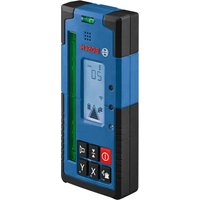
LR40G Professional - Laser rangefinder BOSCH - Free user manual and instructions
Find the device manual for free LR40G Professional BOSCH in PDF.


User questions about LR40G Professional BOSCH
0 question about this device. Answer the ones you know or ask your own.
Ask a new question about this device
Download the instructions for your Laser rangefinder in PDF format for free! Find your manual LR40G Professional - BOSCH and take your electronic device back in hand. On this page are published all the documents necessary for the use of your device. LR40G Professional by BOSCH.
USER MANUAL LR40G Professional BOSCH
IMPORTANT: IMPORTANT : IMPORTANTE: Read Before Using Lire avant usage Leer antes de usar

natural_image
Icon of a person reading a book inside a circle (no text or symbols)Operating/Safety Instructions Consignes de fonctionnement/sécurité Instrucciones de funcionamiento y seguridad
LR40G
natural_image
Exterior view of a Bosch BOSCH portable electronic device with control buttons and antenna (no readable text beyond branding)
BOSCH
Call Toll Free for Consumer Information & Service Locations
natural_image
3D mechanical assembly diagram showing a device emitting light beams from a component, with no visible text or symbols.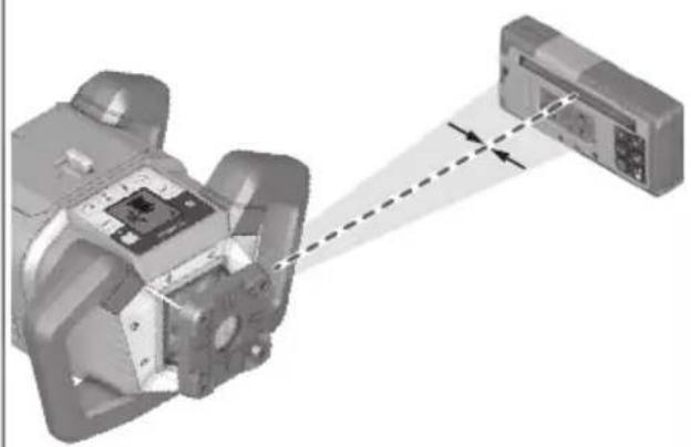
natural_image
3D mechanical assembly diagram showing a component with alignment lines and a close-up view of a device (no text or symbols)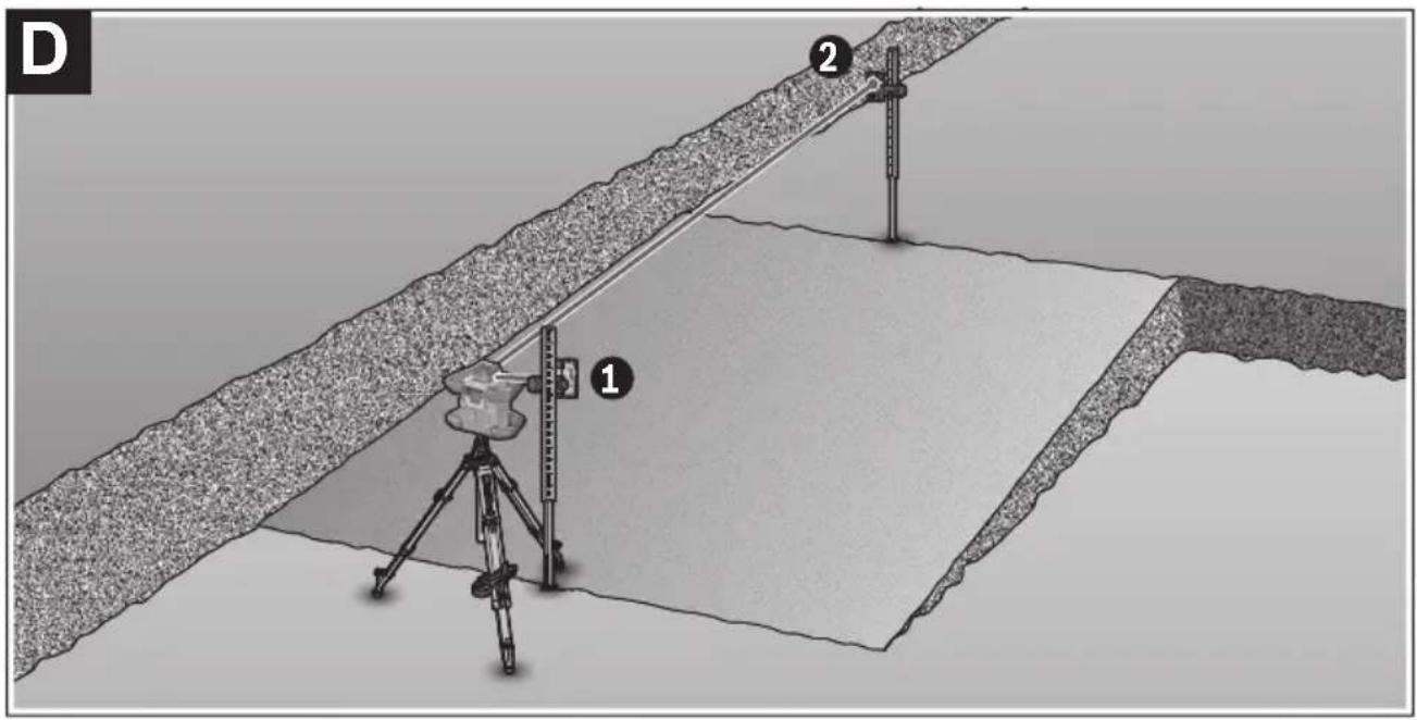
text_image
D 1 2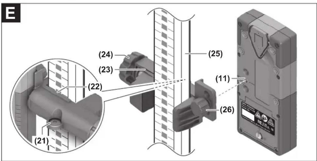
text_image
(24) (23) (22) (21) (25) (11) (26)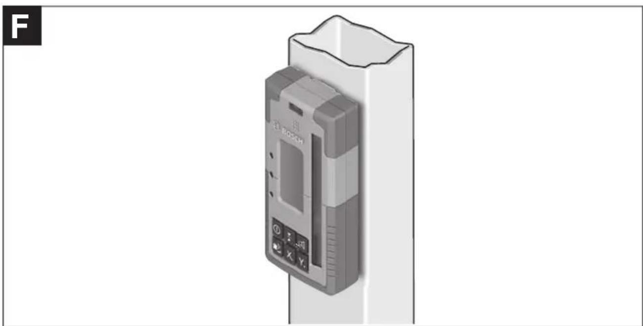
natural_image
3D rendering of a Bosch electronic device mounted on a vertical post (no visible text or symbols)Safety Symbols
The definitions below describe the level of severity for each signal word. Please read the manual and pay attention to these symbols.
 | This is the safety alert symbol. It is used to alert you to potential personal injury hazards. Obey all safety messages that follow this symbol to avoid possible injury or death. |
 | Read manual symbol - Alerts user to read manual. |
 | DANGER indicates a hazardous situation which, if not avoided, will result in death or serious injury. |
 | WARNING indicates a hazardous situation which, if not avoided, could result in death or serious injury. |
 | CAUTION indicates a hazardous situation which, if not avoided, could result in minor or moderate injury. |
 | This symbol designates that this laser leveling tool complies with Part 15 of the FCC Rules. |
LR40G General Safety Rules

WARNING
Read all instructions.
Failure to follow all instructions listed below may
result in hazardous radiation exposure, electric shock, fire and/or serious injury.
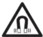
Keep the magnet away from implants and other medical devices, e.g. pacemakers or insulin pumps. The magnet
generates a field that can impair the function of implants and medical devices.
- Have the laser receiver repair through qualified specialists using original spare parts. This ensures that the safety of the laser receiver is maintained.
- Read and strictly observe the warnings in the operating instructions of the rotational laser.
- Do not use the laser recei explosive atmospheres which contain flammable liquids, gases or dust.
Sparks may be produced inside the laser level, which can ignite dust or fumes.
- Keep the laser receiver away magnetic storage media and magnetically-sensitive devices. The effect of the magnets can lead to irreversible data loss.
CAUTION
When using the laser receiver with
Bluetooth®, a fault may occur in other devices and systems, airplanes and medical devices (e.g. pacemakers, hearing aids). Also, damage to people and animals in the immediate vicinity cannot be completely excluded. Do use the laser receiver with Bluetooth® in the vicinity of medical devices, gas stations, chemical plants, areas with a potentially explosive atmosphere and in blasting areas. Do not use the receiver with Bluetooth® on airplanes. Avoid using the product near your body for extended periods.
LR40G General Safety Rules
Noise Information
The A-weighted sound pressure level of the audio signal at one meter distance is 80 dB(A).
WARNING
When operating the laser receiver, loud signal tones
may sound under certain circumstances. For this reason, keep the laser receiver away from your ears and from other persons. The loud sound can damage hearing.
FCC Caution

The manufacturer is not responsible for radio interference caused by unauthorized modifications to this equipment. Such modifications could void the user's authority to operate the equipment.
This device complies with Part 15 of the FCC Rules. Operation is subject to the following two conditions:
1) This device may not cause harmful interference, and
2) This device must accept any interference received, including interference that may cause undesired operation.
NOTE! This equipment has been tested and found to comply with the limits for a Class B digital devices, pursuant to Part 15 of the FCC rules. These limits are designed to provide reasonable protection against harmful interference in a residential installation. This equipment generates uses and can radiate radio frequency energy and, if not installed and used in accordance with the instructions, may cause harmful interference to radio communications. However, there is no guarantee
that interference will not occur in a particular installation. If this equipment does cause harmful interference to radio or television reception, which can be determined by turning the equipment off and on, the user is encouraged to try to correct the interference by one or more of the following measures:
• Reorient or relocate the receiving antenna.
- Increase the separation between the equipment and receiver.
- Connect the equipment into an outlet on a circuit different from that to which the receiver is connected.
- Consult the dealer or an experienced radio/TV technician for help.
"Exposure to Radio Frequency (RF) Signals: The wireless device is a radio transmitter and receiver. It is designed and manufactured not to exceed the emission limit for expos radio frequency (RF) energy set by the Ministry of Health (Canada), Safety Code 6. These limits are part of comprehensive guidelines and established permitted levels of RF energy for the general population.
Industry Canada (IC)
This device complies with Industry Canada's licence-exempt RSSs. Operation is subject to the following two conditions:
(1) This device may not cause interference; and
(2) This device must accept any interference, including interference that may cause undesired operation of the device.
Features
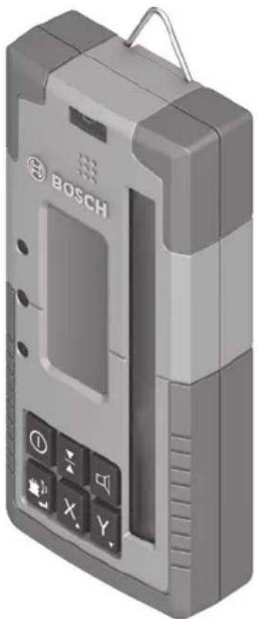
The numbering of the product features shown refers to the illustration of the tool on the graphic page.
(1) Laser beam reception area
(2) "Laser beam over center line" LED direction indicator
(3) LED for center line
(4) "Laser beam below center line" LED direction indicator
(5) Display (front and back)
(6) Speaker
(7) Spirit level
(8) Utility hook
(9) Center mark
(10) Magnets
(11) Attachment for bracket
(12) Serial number
(13) Battery compartment cover
(14) Battery compartment cover locking mechanism
(15) Y-axis button
(16) X-axis button
(17) Mode button for CenterFind
(18) Button for adjusting the reception accuracy
(19) On/off button
(20) Audio signal/volume button
(21) Spirit level for bracket
(22) Center line reference on the bracket
(23) Bracket A)
(24) Rotary knob of bracket
(25) Measuring rod A)
(26) Fastening screw of the bracket
A) Accessories shown or described are not included with the product as standard. You can find the complete selection of accessories in our accessories range.
Display Elements
(a) Battery pack/battery charge indicator for rotary laser
(b) Bluetooth® connection indicator
(c) Indicator for reception accuracy
(f) "Laser beam below center line" direction indicator
(g) Indicator for audio signal/volume
(h) Center line indicator
(i) Battery indicator for laser receiver
(j) “Laser beam over center line” direction indicator
Rotary receiver LR40G
| Article number 3601K69T10 | |||
| Receivable wavelength 500 - 570 nm | |||
| Working range with GRL4000-90CHVG max. ^A) | 2000 ft (610 m) | ||
| Reception angle ±35° | |||
| Receivable rotation speed > 120 min | -1 | ||
| Accuracy setting ^B)C) | (inch) | (decimal) (mm) | |
| - Very fine | ±1/32 | ±0.05 ±0.5 | |
| - Fine | ±1/16 | ±0.1 | ±1 |
| - Medium | ±1/8 | ±0.15 | ±2 |
| - Coarse | ±1/4 | ±0.25 | ±5 |
| - Very coarse | ±1/2 | ±0.5 | ±10 |
| Operating temperature | 14 °F to 122 °F (-10 °C to +50 °C) | ||
| Storage temperature | -4 °F to 158 °F (-20 °C to +70 °C) | ||
| Max. altitude | 6560 ft (approx. 2000 m) | ||
| Relative air humidity max. | 90 % | ||
| Pollution degree according to IEC 61010-1 ^D) | 2 | ||
| Bluetooth® laser receiver | |||
| - Class | 1 | ||
| - Compatibility ^E) | Bluetooth® 5.0/4.X (Low Energy) | ||
| - Max. signal range ^F) | 300 ft (100 m) | ||
| - Operating frequency range | 2402 - 2480 MHz | ||
| - Max. transmission power | 6.3 mW | ||
| Batteries | 2 × 1.5 V LR6 (AA) | ||
| Approx. operating time | 50 h | ||
| Weight according to EPTA-Procedure 01:2014 | 0.84 lb. (0.38 kg) | ||
| Dimensions (length × width × height) | 6.9" × 3" × 1.3" (175 × 79 × 33 mm) | ||
| Protection rating | IP 67 | ||
A) The working range may be reduced by unfavorable environmental conditions (e.g. direct sunlight).
B) Dependent on the distance between the laser receiver and the rotary laser and on the laser class and laser type of the rotary laser.
C) The measuring accuracy may be reduced by unfavorable environmental conditions (e.g. direct sunlight).
D) Only non-conductive deposits occur, whereby occasional temporary conductivity caused by condensation is expected.
E) When using Bluetooth® Low Energy devices, it may not be possible to establish a connection depending on the model and operating system. Bluetooth® devices must support the SPP profile.
F) The signal range may vary greatly depending on external conditions, including the receiving device used. The Bluetooth® range may be significantly weaker inside closed rooms and through metallic barriers (e.g. walls, shelving units, cases, etc.).
For clear identification of your laser receiver, see the serial number (12) on the type plate.
Intended Use
The laser receiver is intended to quickly find rotating laser beams of the wavelength specified in the technical data.
The laser receiver is also intended for controlling the GRL4000-90CHVG via Bluetooth®.
The laser receiver is suitable for indoor and outdoor use.
Assembly
Inserting/Changing the Batteries
Alkali-manganese batteries are recommended for the laser receiver.
Turn the locking mechanism (14) of the battery compartment cover into position ⚙ (e.g. using a coin). Open the battery compartment cover (13) and insert the batteries.
When inserting the batteries, ensure that the polarity is correct according to the illustration on the inside of the battery compartment.
Close the battery compartment cover (13) and turn the locking mechanism (14) of the battery compartment cover into position 🔒.
The battery indicator (i) shows the state of charge of the batteries of the laser receiver:
| Capacity | |
 | 50 - 100% |
 | 5 - 50% |
 | 2 - 5% |
 | 0 - 2% |
Always replace all the batteries at the same time. Only use batteries from the same manufacturer and which have the same capacity.
▶ Take the batteries out of the laser receiver when you are not using it for a prolonged period of time. The batteries can corrode and self-discharge during prolonged storage in the laser receiver.
Battery charge indicator for rotary laser
The battery charge indicator (a) shows the state of charge of the battery pack/batteries of the rotary laser, provided that the rotary laser is switched on and a Bluetooth® connection has been established between the laser receiver and the rotary laser.
| Indicator | Capacity | |
 | 60 – 100% | |
 | 30 – 60% | |
 | 5 – 30% | |
 | 0 – 5% | |
Operation
Starting operation
▶ Protect the laser receiver against moisture and direct sunlight.
▶ Do not subject the laser receiver to extreme temperatures or variations in temperature. As an example, do not leave it in vehicles for longer periods. In case of large variations in temperature, allow the laser receiver to adjust to the ambient temperature before putting it into operation. In case of extreme temperatures or variations in temperature, the accuracy of the laser receiver can be impaired.
▶ Keep the work area free from obstacles that could reflect or obstruct the laser beam. For example, cover any reflective or shiny surfaces. Do not measure panes of glass or similar materials. The measurements may be distorted by a reflected or obstructed laser beam.
Setting up the laser receiver (see figure A)
Position the laser receiver so that the laser beam can reach the reception area (1). Align it so that the laser beam runs straight through the reception area (as shown in the figure).
For rotary lasers with multiple operating modes, select the horizontal or vertical operation with the highest rotational speed.
Switching On/Off
▶ A loud audio signal sounds when switching on the laser receiver. Therefore, keep the laser receiver away from your ear or other persons when switching it on. The loud sound can damage hearing.
To switch on the laser receiver, press the on/off button (19). All display indicators and all LEDs light up briefly and an audio signal sounds.
To switch off the laser receiver, press and hold the on/off button (19) until all LEDs briefly light up and the display goes out. With the exception for the setting of the display lighting, all settings are saved upon switching off.
If no button on the laser receiver is pressed for approx. 10 min and no laser beam reaches the reception area (1) for 10 min, then the laser receiver will automatically switch itself off to preserve battery life.
Connection to the rotary laser
In the default factory setting, the rotary laser and the supplied laser receiver are already connected via Bluetooth®. For the existing connection, the Bluetooth® connection indicator (b) appears in the display of the laser receiver.
In order to reconnect the laser receiver or connect an additional laser receiver with the rotary laser, press and hold the Bluetooth® button on the rotary laser until the symbol for establishing a connection to the remote control/laser receiver appears in the display of the rotary laser. Then press the X-axis button (16) and the Y-axis button (15) on the laser receiver at the same time until P-- appears in the text display (e). Confirmation as to whether a connection has successfully been established will be shown on the display of the rotary laser.
Confirmation as to whether a connection has successfully been established will be shown on the display of the rotary laser. POK will appear on the text indicator (e) of the laser receiver.
If the connection between the rotary laser and the laser receiver cannot be established, PNK will appear in the text display (e) of the laser receiver and the error message for a failed connection will be shown in the display of the rotary laser. For troubleshooting, consult the operating instructions for the rotary laser.
Direction indicators
The position of the laser beam in the reception area (1) is indicated as follows:
- On the display (5) on the front and rear of the laser receiver by means of the "laser beam below center line" direction indicator (f), the "laser beam above center line" direction indicator (j) and the center line indicator (h)
- Optionally, by means of the red "laser beam below center line" LED direction indicator (4), the blue "laser beam above center line" LED direction indicator (2) and the green center line LED (3) on the front of the laser receiver
- By an audio signal (optional).
On the first pass of the laser beam through the reception area (1) a short audio signal always sounds and the red "laser beam below
center line" LED direction indicator (4) and the blue "laser beam above center line" LED direction indicator (2) briefly light up (even if the audio signal and/or LED direction indicators have been switched off).
Laser receiver too low: If the laser beam hits the upper half of the reception area (1), then the “laser beam above center line” direction indicator (j) appears in the display. If the LEDs are switched on, the blue “laser beam above center line” LED direction indicator (2) lights up. If the audio signal is switched on, a signal sounds in a slow rhythm.
Move the laser receiver upwards in the direction of the arrow. When the laser beam is close to the center line, only the tip of the “laser beam above center line” direction indicator (j) is shown.
Laser receiver too high: If the laser beam hits the lower half of the reception area (1), then the “laser beam below center line” direction indicator (f) appears in the display. If the LEDs are switched on, the red “laser beam below center line” LED direction indicator (4) lights up. If the audio signal is switched on, a signal sounds in a fast rhythm.
Move the laser receiver downwards in the direction of the arrow. When the laser beam is close to the center line, only the tip of the "laser beam below center line" direction indicator (f) is shown.
Laser receiver centered: If the laser beam hits the reception area (1) at the height of the center line, then the center line indicator (h) appears in the display. If the LEDs are switched on, the green center line LED (3) lights up. If the audio signal is switched on, a continuous tone sounds.
Memory function of last reception: If the laser receiver is moved so that the laser beam leaves the reception area (1) again, the last displayed direction indicator for “laser beam above center line” (j) or “laser beam below center line” (f) flashes for a short time. This indicator can be switched on or off via the settings menu.
Relative height indicator (see figure B)
If the laser beam hits the reception area (1), the clearance between the laser beam and the center line of the laser receiver is shown in the text display (e) as an absolute value.
The measuring unit for the height indicator can be changed in the settings menu (“mm” or “in”).
Display illumination
The displays (5) on the front and rear of the laser receiver can be illuminated. The display illumination function is switched on:
- When the laser receiver is switched on
- With each press of a button
- If the laser beam moves over the reception area (1).
The display illumination function automatically switches off:
- 30 s after each button press, if no laser beam reaches the reception area
- 2 mins after the last button press and if the position of the laser beam in the reception area does not change
The display illumination function can be switched off in the settings menu. The setting for display illumination is not saved when the laser receiver is switched off. After switching on the laser receiver, the display illumination is always switched on.
Settings
Selecting the setting of the center line indicator
You can specify the accuracy with which the position of the laser beam is indicated as "centered" on the reception area (1).
The current setting for the center line indicator (c) can be seen in the indicator for reception accuracy.
To change the reception accuracy, press the button for adjusting the reception accuracy (18) as many times as needed for the required setting to be shown in the display. With each press of the button for adjusting the reception accuracy, the respective value for the reception accuracy appears in the text display (e) for a short time.
The setting for measuring accuracy is saved when the tool is switched off.
Laser Beam Indicator Audio Signal
The position of the laser beam on the reception area (1) can also be indicated by an audio signal.
The volume level can be changed or the audio signal switched off.
To change the volume level or switch off the audio signal, push the audio signal button (20) until the required volume level is indi-
cated on the display. At a low volume, the audio signal indicator (g) appears on the display with one bar; at a high volume, the indicator appears with three bars. When the audio signal is switched off, the indicator goes out.
Independent of the audio signal setting, a short beep sounds at low volume level when the laser beam first makes contact with the reception area (1).
The setting for the audio signal is saved when the laser receiver is switched off.
Settings menu
To call up the settings menu: Press the X-axis button (16) and the Y-axis button (15) on the laser receiver at the same time.
To change the setting within a submenu: Press the X-axis button (16) or the Y-axis button (15) to switch between the settings. The last selected setting is automatically saved when exiting the menu.
To change the submenu: Briefly press the CenterFind mode button (17) to move to the next submenu.
To exit the settings menu: Press and hold the CenterFind mode button (17) until the settings menu closes. Alternatively, the settings menu is automatically closed approximately ten seconds after the last press of a button.
All settings are saved when the laser receiver is switched off. Except the display backlight setting. It is always on when turning the receiver on.
The following submenus are available:
- Unit of measurement of the relative height indicator: When calling up the unit of measurement menu, the currently selected measuring unit is shown in the text display (e), while the available measuring units are shown in the measuring unit indicator (d) above it.
- LED direction indicators (LED): The three LED direction indicators (2), (4) and (3) can be adjusted with regard to their brightness or switched off. The LEDs light up in their selected setting.
- Display lighting (LIT): The display lighting can be switched on (green LED lights up) or switched off (red LED lights up).
- Memory function for last reception (MEM): The indicator for the direction in which the laser beam has left the reception area can be switched on (green LED lights
up) or switched off (red LED lights up).
- Center functions (CF/CL): You can choose between CenterFind (CF) mode and CenterLock (CL) mode. The current mode appears in the text display (e).
Functions
CenterFind mode (see figure C)
In CenterFind mode, the rotary laser automatically attempts to align the laser beam to the center line of the laser receiver by moving the rotation head up and down.
If the rotary laser is in the horizontal position, the laser beam can be aligned in relation to the X-axis of the rotary laser, to the Y-axis or to both axes at the same time (see “Inclination Determination with CenterFind mode (see figure D)”, page 4). If the rotary laser is in the vertical position, only alignment to the Y-axis is possible.
Start CenterFind mode:
Position the rotary laser and laser receiver so that the laser receiver is situated in the direction of the X-axis or the Y-axis of the rotary laser. Align the laser receiver so that the required axis is at a right angle to the reception area (1). If the laser beam is aligned to both axes, then place a laser receiver connected to the rotary laser in the direction of the X- and Y-axis respectively. Each laser receiver must be situated within the pivoting range of ±8.5% of the rotary laser.
Switch on the rotary laser in rotary operation.
In the settings menu, the center function must be put in CenterFind (CF) mode. When aligning to two axes of the rotary laser, this applies to both laser receivers.
To start CenterFind mode for the X-axis, either press and hold the CenterFind (17) mode button, or press and hold the CenterFind (17) mode button together with the X-axis button (16). To start CenterFind mode for the Y-axis, press and hold the CenterFind (17) mode button, together with the Y-axis button (15). Should the laser beam be aligned to both axes at the same time, CenterFind mode must be started separately on each laser receiver.
Following the start of CenterFind mode, the rotary head on the rotary laser moves up and down. During the search process, CFX (X-axis) or CFY (Y-axis) appears in the text display (e).
If the laser beam hits the reception area (1) at the height of the center line of the laser re-
ceiver, the center line indicator (h) will appear and XOK (X-axis) or YOK (Y-axis) will appear on the display (e). The value of the incline that is found is displayed on the rotary laser. CenterFind mode then ends automatically.
Cancelling CenterFind mode:
To cancel the CenterFind mode, press and hold the CenterFind mode button (17).
Troubleshooting:
If the laser beam was unable to find the center line of the laser receiver within the pivoting range, ERR appears in the text display (e) and all LED direction indicators light up.
Press any button on the rotary laser or laser receiver to close the error message. Reposition the rotary laser and laser receiver so that the laser receiver is situated within the pivoting range of ±8.5% of the rotary laser. Ensure that the laser receiver is aligned to the X-axis or Y-axis so that the laser beam can pass through the reception area (1) horizontally. Then restart the CenterFind mode.
If both axes of the rotary laser should be aligned to a laser receiver, the same center function must be set on both laser receivers. A combination of CenterFind mode and CenterLock mode is not possible. If CenterLock mode is already set on one axis and CenterFind mode is started on the other axis, ERR and CL will appear alternately in the text display (e). Select CenterFind mode on both laser receivers and re-start the function.
Inclination determination with CenterFind mode (see figure D)
Using CenterFind mode, the inclination of a surface can be measured up to max. 8.5%. To do this, set up the rotary laser at one end of the inclined surface in a horizontal position on a tripod. The X- or Y-axis of the rotary laser must be aligned with the inclination to be determined. Switch on the rotary laser and allow it to level in.
Secure the laser receiver to a measuring rod (25) with the bracket. Place the measuring rod near to the laser level (at the same end of the inclined surface). Align the height of the laser receiver on the measuring rod so that the laser beam of the rotary laser is indicated as “centered” ①.
Then place the measuring rod with the laser receiver at the other end of the inclined surface at ●. Ensure that position of the laser receiver on the measuring rod remains unchanged.
Start CenterFind mode for the axis to which the inclined surface is aligned. At the end of CenterFind mode, the inclination of the surface is shown on the rotary laser.
In CenterLock mode, the rotary laser automatically attempts to align the laser beam to the center line of the laser receiver by moving the rotation head up and down. In contrast to the CenterFind mode, the position of the laser receiver is continually checked and the inclination of the rotary laser automatically adjusted. No slope values appear on the display of the rotary laser.
Alignment is possible for the X-axis and Y-axis both when the rotary laser is in a horizontal position and when it is in a vertical position.
Start CenterLock mode:
Position the rotary laser and laser receiver so that the laser receiver is situated in the direction of the X-axis or the Y-axis of the rotary laser. Align the laser receiver so that the required axis is at a right angle to the reception area (1).
If the laser beam is aligned to both axes, then place a laser receiver connected to the rotary laser in the direction of the X- and Y-axis respectively. Each laser receiver must be situated within the pivoting range of ±8.5% of the rotary laser.
Switch on the rotary laser in rotational operation.
In the settings menu of the laser receiver, the center function must be put in CenterLock (CL) mode. When aligning to two axes of the rotary laser, this applies to both laser receivers.
To start the CenterLock mode for the X-axis, either press and hold the CenterFind (17) mode button, or press and hold the CenterFind (17) mode button, together with the X-axis button (16).
To start the CenterLock mode for the Y-axis, press and hold the CenterFind (17) mode button, together with the Y-axis button (15).
Should the laser beam be aligned to both axes at the same time, CenterLock mode must be started separately on each laser receiver.
Following the start of CenterLock mode, the rotary head on the rotary laser moves up and down. During the search process, CLX (X-axis) or CLY (Y-axis) appears in the text display (e).
If the laser beam hits the reception area (1) at the height of the center line of the laser receiver, the center line indicator (h) and LOC is displayed on the text indicator. The Center-Lock symbol is displayed on the rotary laser on the start screen for the corresponding axis.
In the event of changes to the position of the laser receiver or rotary laser, the inclination is automatically adjusted on the rotary laser.
▶ Take great care when working with the CenterLock mode that rotary lasers and laser receivers are not moved unintentionally. Incorrect measurements can arise from the automatic adjustment of the inclination with every change of position.
Cancelling CenterLock mode:
To cancel or end the CenterLock mode, press and hold the CenterFind mode button (17). If the laser beam was already successfully aligned with the center line of the laser receiver at this point, the set inclination remains on the rotary laser even when CenterLock mode is cancelled.
Troubleshooting:
If the laser beam was unable to find the center line of the laser receiver within 2 min (no matter whether at the start of the mode or after changes to position), ERR appears in the text display (e) and all LED direction indicators light up.
Press any button on the rotary laser and one on the laser receiver to close the error messages. Reposition the rotary laser and laser receiver so that the laser receiver is situated within the pivoting range of ±8.5% of the rotary laser. Ensure that the laser receiver is aligned to the X-axis or Y-axis so that the laser beam can pass through the reception area (1) horizontally. Then restart the CenterLock mode.
If both axes of the rotary laser should be aligned to a laser receiver, the same center function must be set on both laser receivers. A combination of CenterLock mode and CenterFind mode is not possible. If CenterFind mode is already set on one axis and CenterLock mode is started on the other axis, ERR and CF will appear alternately in the text display (e). Select CenterLock mode on both laser receivers and re-start the function.
Anti-strobe protection filter
The laser receiver has electronic filters for strobe light. The filters protect against, for example, interference from the warning lights of construction machinery.
Practical Advice
Aligning with the spirit level
The laser receiver can be aligned vertically (plumb line) with the spirit level (7). If a laser receiver is mounted at an angle, it will give incorrect measurements.
Marking
You can mark the position of the laser beam at the center mark (9) on the left and right of the laser receiver when the beam hits the center of the reception area (1).
When marking, take care to align the laser receiver so that it is exactly vertical (with a horizontal laser beam) or horizontal (with a vertical laser beam), as otherwise the marks are offset with respect to the laser beam.
Attaching using the bracket (see figure E)
You can use the bracket (23) to attach the laser receiver to a measuring rod (25) (accessory) as well as to other objects with a width of up to 2.5 in.
Screw the bracket (23) to the mount (11) on the rear side of the laser receiver with the fastening screw (26).
Loosen the rotary knob (24) on the bracket, slide the bracket onto the measuring rod (25) and retighten the rotary knob (24).
You can use a spirit level (21) to ensure that the bracket (23) is horizontally aligned along with the laser receiver. If a laser receiver is mounted at an angle, it will give incorrect measurements.
The center line (22) of the bracket is located at the same height as the center mark (9) and can be used to mark the laser beam.
Attaching using a magnet (see figure F)
If an attachment is not required to be especially secure, the laser receiver can be attached to steel parts using the magnets (10).
| Function possible with LR 65 G and GRL 650 CHVG Rotary laser with green laser beam | ||
| (500–570 nm) | ||
| Battery charge indicator of the rotary laser | ● | - |
| Direction indicators for the position of the laser beam | ● | ● |
| Relative height indicator | ● | ● |
| CenterFind mode | ● | - |
| CenterLock mode | ● | - |
Rectifying errors
| Text display (e) Problem Corrective measure | ||
| PNK Failed to establish Bluetooth® connection to the rotary laser GRL4000-90CHVG | Briefly press the on/off button on the rotary laser to close the error message. Restart the process for establishing the connection.If it is not possible to establish a connection, please contact a Bosch customer service agent. | |
| ERR Failed to calibrate the rotary laser GRL4000-90CHVG | Read and observe the operating instructions for the GRL4000-90CHVG | |
| ERR | CenterFind mode or CenterLock mode failed | Press any button to close the error message. Check the position of the rotary laser and laser receiver before restarting the function. |
| ERR and CL in alternation | CenterFind mode cannot be started because the rotary laser is already working in CenterLock mode. | Select CenterFind mode on both laser receivers and restart the function. |
| ERR and CF in alternation | CenterLock mode cannot be started because the rotary laser is already working in CenterFind mode. | Start CenterLock mode on both laser receivers and restart the function. |
Maintenance and Service

Store and transport the tool only in the supplied protective case.
Check the tool each time before using.
Keep the tool clean and dry at all times to ensure proper and safe operation.
Do not immerse the tool into water or other fluids.
Wipe off debris using a moist and soft cloth. Do not use any cleaning agents or solvents.
Regularly clean the surfaces at the exit opening of the laser.
In case of visible damage or loose components in the interior of the tool, the safe function is no longer ensured.
If the tool should fail despite the care taken in manufacturing and testing procedures,
repair should be carried out by an authorized after-sales service center for Bosch power tools.
In all correspondence and spare parts orders, please always include the 10-digit article number given on the type plate of the tool.
In case of repairs, send in the tool packed in its protective case.
ENVIRONMENT PROTECTION

Recycle raw materials & batteries instead of disposing of waste. The unit, accessories, packaging & used batteries should be sorted for environmentally friendly recycling in accordance with the latest regulations.
LIMITED WARRANTY OF BOSCH LASER AND MEASURINGTOOLPRODUCTS
Robert Bosch Tool Corporation (“Seller”) warrants to the original purchaser only, that all Bosch lasers and measuring tools will be free from defects in material or workmanship for a period of one (1) year from date of purchase. Bosch will extend warranty coverage to two (2) years when you register your product within eight (8) weeks after date of purchase. Product registration card must be complete and mailed to Bosch (postmarked within eight weeks after date of purchase), or you may register on-line at www.boschtools.com/Service/ProductRegistration. If you choose not to register your product, a one (1) year limited warranty will apply to your product.
30 Day Money Back Refund or Replacement -
If you are not completely satisfied with the performance of your laser and measuring tools, for any reason, you can return it to your Bosch dealer within 30 days of the date of purchase for a full refund or replacement. To obtain this 30-Day Refund or Replacement, your return must be accompanied by the original receipt for purchase of the laser or optical instrument product. A maximum of 2 returns per customer will be permitted.
SELLER'S SOLE OBLIGATION AND YOUR EXCLUSIVE REMEDY under this Limited Warranty and, to the extent permitted by law, any warranty or condition implied by law, shall be the repair or replacement of parts, without charge, which are defective in material or workmanship and which have not been misused, carelessly handled, or misrepaired by persons other than Seller or Authorized Service Center. To make a claim under this Limited Warranty, you must return the complete Bosch laser or measuring tool, transportation prepaid, to any BOSCH Factory Service Center or Authorized Service Center. Please include a dated proof of purchase with your tool. For locations of nearby service centers, please use our on-line service locator or call 1-877-267-2499.
THIS WARRANTY PROGRAM DOES NOT APPLY TO TRIPODS AND RODS. Robert Bosch Tool Corporation (“Seller”) warrants tripods and leveling rods for a period of one (1) year from date of purchase.
THIS LIMITED WARRANTY DOES NOT APPLY TO OTHER ACCESSORY ITEMS AND RELATED ITEMS. THESE ITEMS RECEIVE A 90 DAY LIMITED WARRANTY.
To make a claim under this Limited Warranty, you must return the complete product, transportation prepaid. For details to make a claim under this Limited Warranty please visit www.boschtools.com or call 1-877-267-2499.
ANY IMPLIED WARRANTIES SHALL BE LIMITED IN DURATION TO ONE YEAR FROM DATE OF PURCHASE. SOME STATES IN THE U.S., AND SOME CANADIAN PROVINCES DO NOT ALLOW LIMITATIONS ON HOW LONG AN IMPLIED WARRANTY LASTS, SO THE ABOVE LIMITATION MAY NOT APPLY TO YOU.
IN NO EVENT SHALL SELLER BE LIABLE FOR ANY INCIDENTAL OR CONSEQUENTIAL DAMAGES (INCLUDING BUT NOT LIMITED TO LIABILITY FOR LOSS OF PROFITS) ARISING FROM THE SALE OR USE OF THIS PRODUCT. SOME STATES IN THE U.S., AND SOME CANADIAN PROVINCES DO NOT ALLOW THE EXCLUSION OR LIMITATION OF INCIDENTAL OR CONSEQUENTIAL DAMAGES, SO THE ABOVE LIMITATION MAY NOT APPLY TO YOU.
THIS LIMITED WARRANTY GIVES YOU SPECIFIC LEGAL RIGHTS, AND YOU MAY ALSO HAVE OTHER RIGHTS WHICH VARY FROM STATE TO STATE IN THE U.S., OR PROVINCE TO PROVINCE IN CANADA AND FROM COUNTRY TO COUNTRY.
THIS LIMITED WARRANTY APPLIES ONLY TO PRODUCTS SOLD WITHIN THE UNITED STATES OF AMERICA, CANADA AND THE COMMONWEALTH OF PUERTO RICO. FOR WARRANTY COVERAGE WITHIN OTHER COUNTRIES, CONTACT YOUR LOCAL BOSCH DEALER OR IMPORTER.
Industry Canada (IC)
This page was intentionally left blank
This page was intentionally left blank
© Robert Bosch Tool Corporation 1800 W. Central Road Mt. Prospect, IL 60056-2230
Exportado por: Robert Bosch Tool Corporation Mt. Prospect, IL 60056-2230, E.U.A.
text_image
Barcode image with black and white vertical bars, no visible text or symbols beyond the pattern2610067498