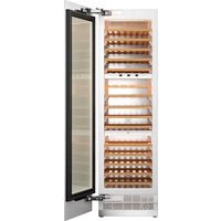
RWC60S5TPNS - Fridge BERTAZZONI - Free user manual and instructions
Find the device manual for free RWC60S5TPNS BERTAZZONI in PDF.


| Product Type | Built-in Wine Cellar |
| Brand | Bertazzoni |
| Model | RWC60S5TPNS |
| Capacity (Bordeaux bottles) | 100 |
| Temperature Zones | 3 independent zones |
| Temperature Range per Zone | 5°C to 20°C (41°F to 68°F) |
| Dimensions (H x W x D) | 2123 x 603 x 616 mm (with panel) |
| Power Supply | 220-240 V ~ 50 Hz, 0.8 A |
| Recommended Fuse | 15 A |
| Climate Class | SN, N, ST, T |
| Refrigerant | R600a (isobutane) |
| Interior Lighting | LED, amber/blue/white colors, adjustable intensity |
| Charcoal Filter | Yes, recommended replacement every 3 to 6 months |
| Defrost | Automatic |
| Child Lock | Yes |
| Open Door Alarm | Yes (after 60 seconds) |
| Sabbath Mode | Yes |
| Exhibition Mode | Yes |
| Door Reversal | Possible (left or right) |
| Installation Type | Built-in (under-counter integration) |
| Maximum Custom Door Panel Weight | 30 kg |
| Main Material | Stainless Steel |
Frequently Asked Questions - RWC60S5TPNS BERTAZZONI
User questions about RWC60S5TPNS BERTAZZONI
0 question about this device. Answer the ones you know or ask your own.
Ask a new question about this device
Download the instructions for your Fridge in PDF format for free! Find your manual RWC60S5TPNS - BERTAZZONI and take your electronic device back in hand. On this page are published all the documents necessary for the use of your device. RWC60S5TPNS by BERTAZZONI.
USER MANUAL RWC60S5TPNS BERTAZZONI
| EN | INSTALLATION MANUAL USER AND MAINTENANCE MANUAL RWC60S5TPNS RWC45S5TPLS RWC45S5TPRS | 3 |
| IT | MANUALE D'INSTALLAZIONE MANUALE D'USO E MANUTENZIONE RWC60S5TPNS RWC45S5TPLS RWC45S5TPRS | 59 |
| FR | MANUEL D'INSTALLATION MANUEL D'UTILISATION ET D'ENTRETIEN RWC60S5TPNS RWC45S5TPLS RWC45S5TPRS | 115 |
| NL | INSTALLATIEHANDLEDING GEBRUKS- EN ONDERHOUDSHANDLEIDING RWC60S5TPNS RWC45S5TPLS RWC45S5TPRS | 175 |
| SV | INSTALLATIONSHANDBOK BRUKS- OCH UNDERHÄLLSHANDBOK RWC60S5TPNS RWC45S5TPLS RWC45S5TPRS | 235 |
FROM THE DESK OF OUR PRESIDENT
Dear new owner of a Bertazzoni appliance,
I want to thank you for choosing one of our beautiful products for your home.
My family started manufacturing kitchen appliances in Italy in 1882, building a reputation for quality of engineering and passion for good food.
Today, our products stand out because of their unique blend of authentic Italian design and superior appliance technology. It is our mission to make products that function perfectly and bring joy to their owners.
By making beautiful products we respond to our customers' flair for good design. By making them versatile and easy-to-use, cooking with Bertazzoni becomes a real pleasure.
This manual will help you learn to use and care for your Bertazzoni appliance in the safest and most effective way, so that it can give you the highest satisfaction for years to come.
Enjoy!
Paolo Bertazzoni
President
f 即 43z = 1
MANUAL VALIDITY
The following manual is valid for all the product codes mentioned below:
RWC60S5TPNS
RWC45S5TPLS
RWC45S5TPRS
GENERAL INFORMATION 7
MANUAL INFORMATION 7
SAFETY INFORMATION 8
CARING FOR THE ENVIRONMENT 10
CONFORMITY 10
ENERGYSAVING 10
MOVING THE APPLIANCE 11
SPECIFICATIONS 12
APPLIANCE DESCRIPTION 12
TECHNICAL SPECIFICATIONS 12
ROOM TEMPERATURE 12
INSTALLATION INSTRUCTIONS 13
PREPARING FOR INSTALLATION 13
CABINET DIMENSIONS 14
PRODUCT DIMENSIONS 16
CUSTOMDOOR PANEL 17
ANTI TIP BRACKETS LOCATION 18
ELECTRICAL REQUIREMENTS 19
VENTILATION 20
TOOL LIST 21
UNPACKING 21
REMOVING THE VENT HOLE ASSEMBLY 22
REVERSING THE DOOR (IF APPLICABLE) 23
INSTALLATION INSTRUCTION (DOOR ON DOOR HINGE) 28
MOUNTING THE ANTI-TIP BRACKETS 29
INSTALLATION IN THE CABINET 32
SCREWING THE SIDE AND UPPER BRACKETS 34
ADJUSTING THE HEIGHT 34
ADJUSTING THE REFRIGERATOR ACCORDING TO THE CABIN FLANGE 36
ATTACHING THE VENT HOLE ASSEMBLY 37
ATTACHING THE DECORATIVE PARTS 37
REMOVING THE PANEL-ADJUSTMENT MECHANISMS ON THE REFRIGERATOR 38
PREPARING FURNITURE DOOR 38
INSTALLING THE FURNITURE DOOR 39
LIMITING PINS 41
REMOVING THE SHELVES 42
ENSURING THE DOOR SEALS CORRECTLY 42
USE 43
BEFORE FIRST USE 43
INTERNAL STORAGE 44
CARBON FILTER 48
RECOMMENDATIONS FOR STORING AND SERVING WINE 49
CONTROL PANEL 51
CARE AND MAINTENANCE 54
LED LIGHT REPLACEMENT INSTRUCTIONS 54
CLEANING THE INTERIOR SURFACES 54
CLEANING THE EXTERIOR SURFACES 54
DEFROSTING 54
NOISES AND MEANING 54
POWER FAILURE 54
TROUBLESHOOTING 55
ERROR CODES 56
WARRANTY AND SERVICE 57
MANUAL INFORMATION
These instructions are suitable for different types of appliances, so they may contain descriptions of functions which your appliance may not include or support.
The images and illustrations in this document refer to various models and may differ slightly from the product purchased.
The manufacturer does not accept any liability for personal injury or damage to property arising from incorrect installation or misuse of the appliance.
The manufacturer reserves the right to modify the various models as required to comply with the technical regulations in force.
In the event of complaints, please contact customer service. Read the instructions provided in this manual thoroughly before installing and/or using the appliance. This will help you get to know your new appliance. Keep this document at hand so that you can consult it at any moment, and pass it on to any subsequent owners.
Read the safety messages provided in the introduction to this manual and give due consideration to the safety notes, such as: "Attention", "Warning" and "Danger" which appear in the text.

DANGER
This symbol indicates a situation that is a danger to you and others. Read it carefully and make sure that you have perfectly understood the causes of potential dangerous or fatal accidents.

WARNING
This symbol indicates safety information. Read it carefully and make sure that you have perfectly understood the causes of potentially dangerous accidents.

CAUTION
This symbol indicates a procedure which could put the appliance's structure or components at risk. Take particular care over these procedures.

NOTE
This symbol highlights methods or procedures for correct use of the appliance.
The Model, Sales Code and Serial Number are printed on the nameplate. Refer to the Specifications section of this manual for nameplate location.

NOTE
You are advised to make a note of the appliance's data and serial numbers so they are immediately available if required.

NOTE
State the information provided on the nameplate to improve the efficiency of the after-sales and parts services. For warranty purposes, you will also need the date of installation and name of your authorized Bertazzoni dealer.

WARNING
When using your appliance, follow basic precautions. Read all instructions before using the appliance. Save these instructions and pass them on to any future user.
SAFETY INFORMATION
This appliance is intended to be used in residential and other similar applications, such as:
Staff kitchen areas in shops, offices and other working environments;
In farm houses and by guests at hotels, motels and other residential type environments;
Bed and breakfast type environments;
- Catering and similar non-retail applications.
It must not be used in any way other than that which it is intended. It must be used only for storing wine.
The manufacturer shall not be held liable for any damages resulting from improper use or transport.
Original spare parts will be available for 10 years following the product's purchase date.
AVOIDING PLACING CHILDREN AND VULNERABLE PEOPLE AT RISK
This appliance is not intended for use by individuals (including children) with reduced physical or sensory capabilities or lack of experience and knowledge unless they are supervised or have been given instruction concerning the use of the appliance by a person responsible for their safety.
Children should be supervised to ensure that they do not play with the appliance.
Cleaning and care should not be performed by children unless they are supervised by an adult.
Keep the appliance and its cord out of reach of children who are less than 8 years old.
RISK OF ELECTRIC SHOCK
Make sure the appliance is unplugged during installation, maintenance, cleaning, and repairs.
- When installing the appliance, ensure that the mains cable is not trapped or damaged.
If the power cord of this appliance is damaged, it must be replaced by the manufacturer, customer service or a similarly qualified person. Improper installations and repairs may put the user at considerable risk.
- Do not use an adapter. Do not use an extension cord.
- Do not plug in the refrigerator if the wall socket is loose.
- Do not pull on the cable to unplug the appliance.
- Unplug the appliance if you encounter a malfunction during use. If the unit malfunctions, it must not be used until it has been repaired by an Authorized Service Provider. The manufacturer cannot be held responsible for damages arising from procedures performed by unauthorized persons.
- Never wash the appliance by pouring, daubing, or spraying water onto it. Never touch the plug with wet hands.
- Never use steam or steam cleaners to clean or defrost the refrigerator. Steam can cause a short circuit or electric shock if it comes into contact with your refrigerator's electrical components.
- Never connect your refrigerator to an energy saving device. Such systems are harmful to your appliance.
RISK OF EXPLOSION
- Do not use electrical appliances of any kind inside of the food storage compartments.
- Do not use mechanical devices or other means to accelerate the defrosting process; use only those recommended by the manufacturer.
- Do not store explosive substances, such as aerosol cans with a flammable propellant, inside this appliance.
Bottles containing beverages with a high alcohol content must be tightly closed and stored vertically.
RISK OF INJURY
- Do not put carbonated beverages or liquids in tins or glass containers in the freezer compartment. They may burst.
- Never use refrigerator components such as the door or drawers as means of support or as steps. This may cause the appliance to tip over or damage it.
- Do not sit on the appliance and do not place heavy objects on top of the appliance.
- Do not sit or lean on the door or on any open drawers.
- Do not put pressure on the door or use it to move the appliance.
- Do not overload the refrigerator. Objects in the refrigerator may fall when the door is opened, causing injury or property damage.
- Do not place your hands or any other body part in the moving parts of the refrigerator (i.e., automatic ice maker).
RISK OF SUFFOCATION
- Packaging materials can be hazardous to children. Do not allow children to play with plastic bags, plastic film, or polystyrene.
If there is a lock on the door of the appliance, the key should be kept out of reach of children.
RISK OF FOOD POISONING
- Store raw meat and fish in the refrigerator in appropriate containers so that it does not come into contact with or drip onto other foods.
- Avoid leaving the door open for long periods of time, as this can cause the temperature inside the appliance compartments to rise significantly.
- Regularly clean surfaces that may come in contact with food and accessible drainage systems.
- If the refrigerator is to be left unused for an extended period of time, turn it off, defrost, clean, dry, and leave the door open to prevent mold from growing inside the appliance.
FIRE HAZARD / ISOBUTANE WARNING

The refrigerant circuit of the appliance contains isobutane (R600a), a natural gas with a high level of environmental friendliness, but which is nevertheless flammable.
During transport and installation of the appliance, take care not to damage any of the components of the refrigerant circuit.
This appliance is CFC and HFC free.
If the refrigerant circuit should become damaged:
- avoid naked flames and sources of ignition.
- thoroughly ventilate the room in which the appliance is located.

NOTE
If the appliance is damaged or if you see a gas leak, please keep away from the gas. It may cause ice burn if it comes into contact with the skin.

NOTE
The type of gas used in the product is listed on the rating label, which is located on the left interior wall of the refrigerator.

CAUTION
- Do not damage areas where refrigerant is circulating with drilling or cutting tools. If the gas ducts in the evaporator, the tubing extensions or the surface coatings are punctured, the refrigerant could blow out, causing skin irritation and eye injuries. Do not use pointed or sharp-edged implements to remove frost or layers of ice. You could damage the refrigerant tubes. Leaking refrigerant may cause eye injuries or ignite.
- Never attempt to extinguish a flame/fire with water: turn off the appliance and cover the flame with a fireproof blanket.
- Do not cover or allow any object to block the ventilation openings in your refrigerator.
CARING FOR THE ENVIRONMENT

This appliance complies with European directive 2012/19/EU (RoHS).
This appliance is tagged in accordance v European directive 2012/19/EC regarding waste electrical and electronic equipment (WEEE).
This directive contains the regulations governing the collection and recycling of decommissioned appliances throughout the European Union.
The unit you have purchased conforms to the EU RoHS Directive (2011/65/EU). It does not contain materials specified in the Directive as harmful or prohibited. This appliance does not contain hazardous substances for the atmospheric ozone layer, neither in the refrigeration circuit nor in the insulation.
Our appliances are packaged in non-polluting and recyclable materials in accordance with National Environmental Regulations:
- Dispose of packaging in an environmentally friendly manner.
- Please ask your dealer to inquire at your local authority about current means of disposal.
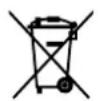
The symbol of a waste bin with a cross over it which appears on the product indicates that Waste Electrical and Electronic Equipment (WEEE) must not be thrown away with ordinary urban waste but must be disposed of separately, so it can undergo special processing to enable its reuse or specific treatment for safe removal and disposal of any substances harmful to the environment and extraction of raw materials which can be recycled.
Therefore, WEEE must be delivered to Recycling Centres run by Municipal Authorities or Waste Management Companies. What's more, when a new appliance is purchased WEEE can be consigned to the retailer, who is obliged to take it back free of charge ("1:1" take-back "Very small" WEEE (with no dimension exceeding 25 cm) can be consigned to retailers free of charge even when no purchase is made ("0:1" take-back - which however is only compulsory for stores with sales area of over 400 m
Pay special attention to correct disposal procedures for all the packaging materials. Before disposal:
Disconnect the mains power supply.
Unplug the appliance and cut the power cord.
- Avoid damaging the refrigeration circuit during disposal.

WARNING
Please ensure that old and worn-out appliances are rendered unusable before disposal by removing the plug, cutting the power cord and removing or destroying the clips or snap bolts. This will prevent children from locking themselves in the appliance during play (risk of suffocation) or endangering their lives in any other way.
For Ecodesign tests, the installation and set-up of the appliance must comply with standard EN 62552.
- Ventilation requirements, dimensions and minimum space from the rear wall are provided in the Installation Note Manual.
- Contact the manufacturer for additional information.

NOTE
Do not dispose of this appliance with regular household waste.
CONFORMITY
By placing the mark on this product, we are confirming compliance with all relevant European safety, health and environmental requirements which are applicable to this product by law.
ENERGY SAVING
For optimal energy saving, we recommend the following:
Install the appliance away from heat sources, out of direct sunlight and in a well-ventilated room.
- Do not overfill the compartments, as this prevents air from circulating properly.
- In the event of an electrical power failure, it is advisable to keep the refrigerator door closed.
- Open the appliance doors as infrequently and for the briefest amounts of time possible.
- Ensure that the unit is adequately ventilated. Never cover air vents.
- Never cover shelves with aluminum foil or any other shelf material which may prevent air circulation.
- Should the appliance be left empty for long periods of time, it is advisable to unplug it and, after thorough cleaning, to leave the door ajar to allow air to circulate inside the cabinet in order to prevent the formation of condensation, mould or odours.
MOVING THE APPLIANCE
Should you need to relocate your appliance, take the following precautions:
- Remove all items from the unit.
- Securely tape down all loose items (e.g. shelves) inside the appliance.
- Turn the adjustable feet at the base clockwise until they are fully raised to avoid damaging them.
- Tape the door shut.
- Ensure the appliance remains in an upright position during transport.
- Protect the outer glass door with a blanket or similar during transport.
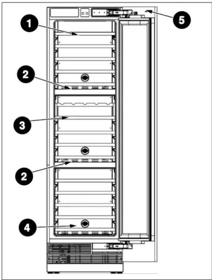
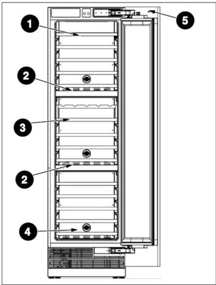
APPLIANCE DESCRIPTION
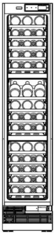
Fig. 1
TECHNICAL SPECIFICATIONS
| ELEMENT | DESCRIPTION |
| Plug type | SCHUKO |
| Voltage 220 V – 240 V | |
| Frequency 50 Hz | |
| Fuse 15 A | |
| Amperage 0.8 A | |
| Capacity 68 Bordeaux bottles for 45cm (18") wine column | |
| 100 Bordeaux bottles for24" (60 cm) wine column | |
Refrigerant, volume and further technical specifications can be found on the rating plate.
ROOM TEMPERATURE
The permitted room temperature depends on the climate class:
| CLIMATE CLASS PERMITTED ROOM TEMPERATURE | |
| SN (Sub Normal) + 10 °C to + 32 °C | |
| N (Normal) | + 16 °C to + 32 °C |
| ST (Sub Tropical) | + 16 °C to + 38 °C |
| T (Tropical) | + 16 °C to + 43 °C |
1) Wine Shelf A
3) Wine Shelf B
2) Control Panel & Compartment Wall
4) Carbon Filter
5) Electromagnetic Switch

NOTE
The figures in this user manual are schematic and may not match the product exactly. If your product does not have the parts described, the information applies to other models.
PREPARING FOR INSTALLATION
This appliance must not be installed close to heat sources, e. g. heating elements or cookers, or in a damp location.
Seek the help of one or two other individuals when installing this appliance. This appliance may have sharp edges. Wear PPE appropriate to the task and environment.
- Use the height-adjustable feet at the front of the appliance to ensure that the appliance is level.
-
The cooling system on the back of the appliance must not touch the rear wall. The larger the gap, the better.
-
The appliance must be installed with adequate ventilation. Ensure that there is clearance above the appliance to allow air to escape and that there is space between the rear of the appliance and the wall.
Plug the appliance into an exclusive, easily accessible electrical socket.
Any questions concerning power and/or electrical connection should be directed towards a qualified electrician or an authorized products service center.
CABINET DIMENSIONS
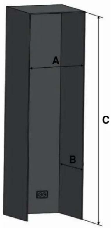
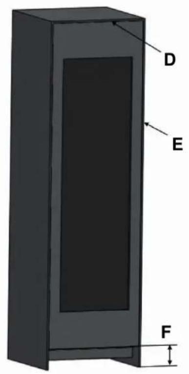
Fig. 2
| CATEGORY RWC45S5TPLS / RWC45S5TPRS RWC60S5TPNS | ||
| A | 457 mm (18") 609 mm (24") | |
| B | 635 mm (25") 635 mm (25") | |
| standard 2134 mm (84") | standard 2134 mm (84") | |
| C | minimum 2127 mm (83 3/4") | minimum 2127 mm (83 3/4") |
| maximum 2167 mm (85 5/16") | maximum 2167 mm (85 5/16") | |
| D | 3 mm (1/8") 3 mm (1/8") | |
| E | 3 mm (1/8") 3 mm (1/8") | |
| standard 101 mm (4") | standard 101 mm (4") | |
| F | minimum 95 mm (3 3/4") | minimum 95 mm (3 3/4") |
| maximum 135 mm (5 5/16") | maximum 135 mm (5 5/16") | |
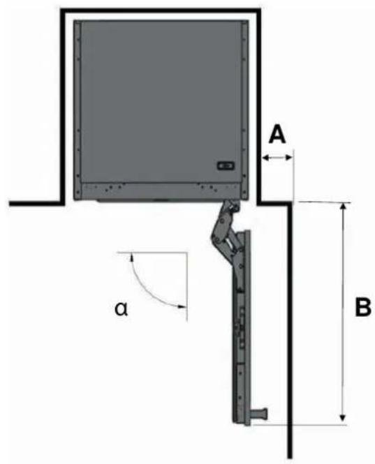
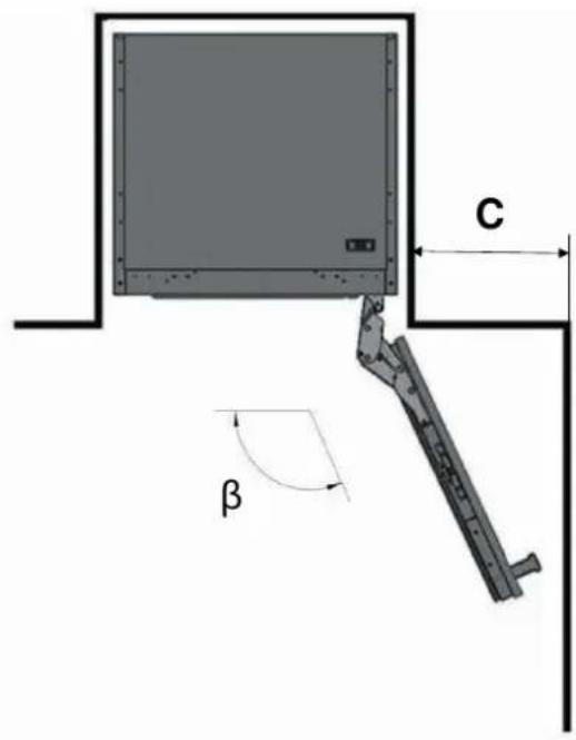
Fig. 3
a 90°
β 115°
CATEGORY RWC45S5TPLS / RWC45S5TPRS RWC60S5TPNS
| A | 111 mm (4 3/8") 111 mm (4 3/8") |
| B | 508 mm (20") 660 mm (26") |
| C | 280 mm (11") 356 mm (14") |
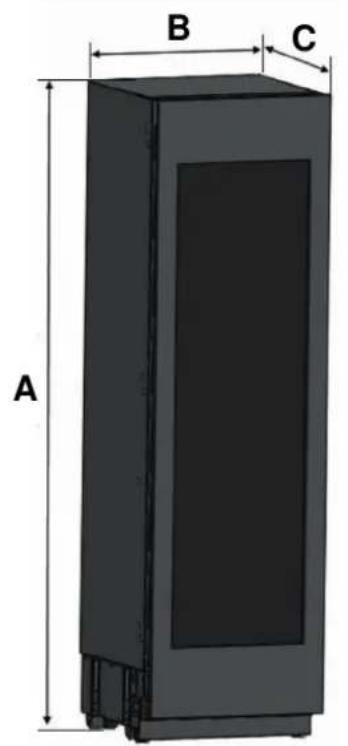
PRODUCT DIMENSIONS
Fig. 4
| CATEGORY RWC45S5TPLS / RWC45S5TPRS RWC60S5TPNS | ||
| A | 2123 mm (83 9/16") 2123 mm (83 9/16") | |
| B | 451 mm (17 3/4") 603 mm (23 3/4") | |
| C | without panel 597 mm (23 1/2") | without panel 597 mm (23 1/2") |
| with panel 616 mm (24 1/4") | with panel 616 mm (24 1/4") | |
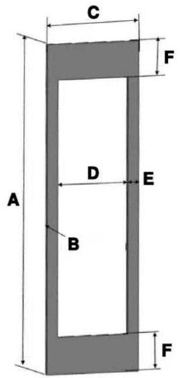
CUSTOM DOOR PANEL
Fig. 5
CATEGORY RWC45S5TPLS / RWC45S5TPRS RWC60S5TPNS
| A | 2030 mm (79 15/16") 2030 mm (79 15/16") |
| B | 19 - 38 mm (3/4" - 1 1/2") thickness 19 - 38 mm (3/4" - 1 1/2") thickness |
| C | 451 mm (17 3/4") 603 mm (23 3/4") |
| D | 311 mm (12 1/4") 463 mm (18 1/4") |
| E | 70 mm (2 3/4") 70 mm (2 3/4") |
| F | 230 mm (9 1/16") 230 mm (9 1/16") |
Max weight of custom door panel: 30kg (66 lbs).
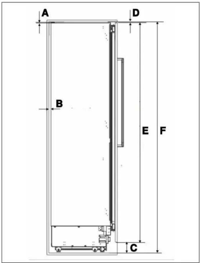
ANTI TIP BRACKETS LOCATION
Fig. 6
| CATEGORY RWC45S5TPLS / RWC45S5TPRS RWC60S5TPNS | |
| A | 2 mm (1/16") 2 mm (1/16") |
| B | 19 mm (3/4") 19 mm (3/4") |
| C | 101 mm (4") 101 mm (4") |
| D | 3 mm (1/8") 3 mm (1/8") |
| E | 2030 mm (79 15/16") 2030 mm (79 15/16") |
| F | 2134 mm (84") 2134 mm (84") |
MINIMUM HEIGHT ADJUSTMENT FOR LEVELING
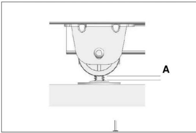
Fig. 7
A. 8 ~mm(5 / 16^ )
ASSEMBLY DIMENSION BETWEEN WOOD PANEL AND FRIDGE DOOR
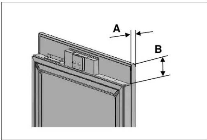
Fig. 8
A. 19 ~mm (3 / 4^ )
B. 82 ~mm (33 / 8^ )
ELECTRICAL REQUIREMENTS
The appliance must be installed to all electrical connections in accordance with state and local codes.

CAUTION
Do not use extension cords or two-prong adapters and do not remove the ground terminal of the grounding cable.

CAUTION
A qualified electrician must ensure that the poles of the socket are connected correctly.
Verify that the grounding of the socket is correct.

WARNING
Do not connect the appliance to electronic energy saver plugs.
The socket must comply with the following data:
| ELECTRICAL REQUIREMENTS | |
| Plug type | SCHUKO |
| Outlet | 2-prong |
| Voltage 220 V – 240 V | |
| Frequency 50 Hz | |
| Fuse 15 A | |
The appliance must be plugged into its own individual electrical outlet with a voltage rating that matches the rating label on the appliance. This provides the best performance and also prevent overloading wiring circuits that could cause a fire hazard from overheating.

IMPORTANT
Do not use extension cords and/or multiple adapters for the power supply connection.
If the electrical wiring or the electric power supply of the house requires alteration, the necessary procedures must be performed by a qualified electrician.
Please heed the following rules:
The electrical outlet or panel must be easily accessible in case of an emergency; it must not be hidden behind the product.
- Neither the plug nor the cable may touch the back surface of the appliance. Otherwise, it may be damaged by the appliance's vibrations.
To prevent accidental injury, the cord should be secured behind the appliance and not left exposed or dangling. - Do not connect other equipment plugs behind this appliance. If the humidity level is high where the appliance is being used, its exterior surfaces may become corroded. To prevent corrosion, keep the installation room dry and well-cleaned.
To prevent the risk of electric shock:
- Connect the plug to a grounded outlet.
- Do not remove plug's grounding prong.
- Do not use adapters.
- Do not use extension cords.
- Neyer unplug the appliance by pulling the power cord.

CAUTION
Do not connect the grounding cable to the gas line. Please have the grounding checked by a qualified electrician if you are not sure about the grounding of the appliance. Do not install a fuse on the neutral line or on the grounding circuit.

CAUTION
Failure to follow these instructions may result in fire, electric shock or death. Connecting the appliance's grounding conductor in the wrong place may lead to electric shock. Please have the grounding checked by a qualified electrician or service technician if you have any doubt about the proper grounding of the appliance. Installation, repairs and other procedures performed by unqualified persons may give rise to hazards. Before installing the appliance, make sure that the voltage, load and circuit current parameters on the data plate are in compliance with the power supply in your house.
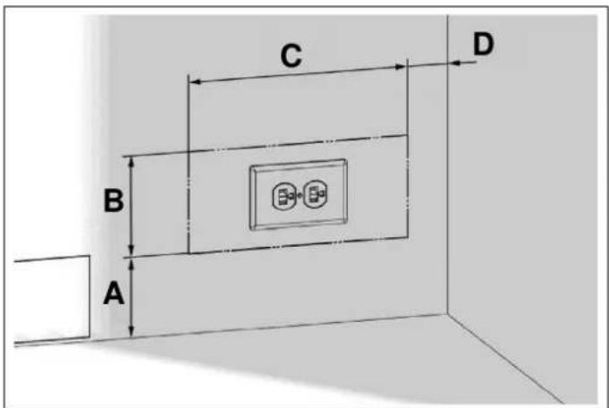
Fig. 9
A 102mm(4^ )
B 127mm(5^ )
C 280 mm (11")
D 50.8 ~mm(2^ )
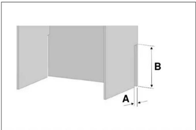
Fig. 10
A 50.8mm(2^ )
B 203.2 mm (8")
VENTILATION
The heat removed from the cooling compartment needs to be dissipated into the air around the appliance. Incorrect ventilation can lead to premature compressor failure, excessive power consumption and total system failure, and it may invalidate the warranty provided with the appliance.
There is a air ventilation grille at the base of the appliance.
The clearance at the rear of the appliance is clearly shown.

NOTE
The air vent at the front of the appliance must never be covered or blocked in any way.
TOOL LIST
The tools to be used when installing the product are as follows:
Cordless drill
Safety goggles
12.7 mm (1/ 2") spanner
Hammer

Ladder

0.2.4 mm drill bit
0 8.0 mm drill bit
Box cutter

Safety gloves Tape measure
Phillips-head bit
6.4 mm (1/4") hex bit
Bubble level
Appliance trolley

Tape

T25 Torx Bits
UNPACKING

WARNING
At least two people must carry the refrigerator.
Use a box cutter to remove the tape.
- Cut the cardboard packaging along the dotted lines using a box cutter and remove it.
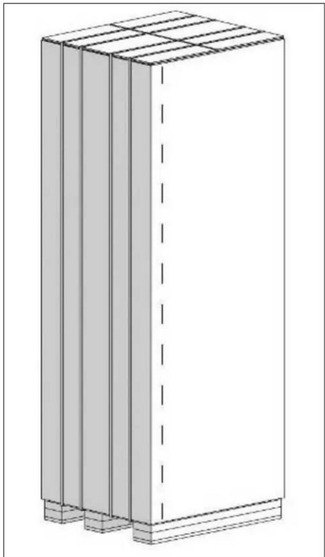
Fig. 11
- Remove the polystyrene packing material.
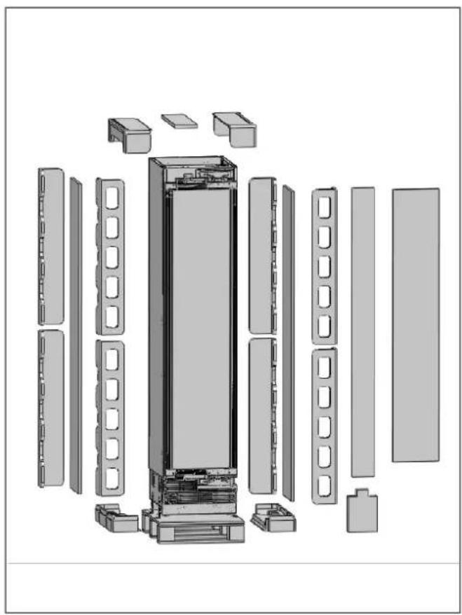
REMOVING THE VENT HOLE ASSEMBLY
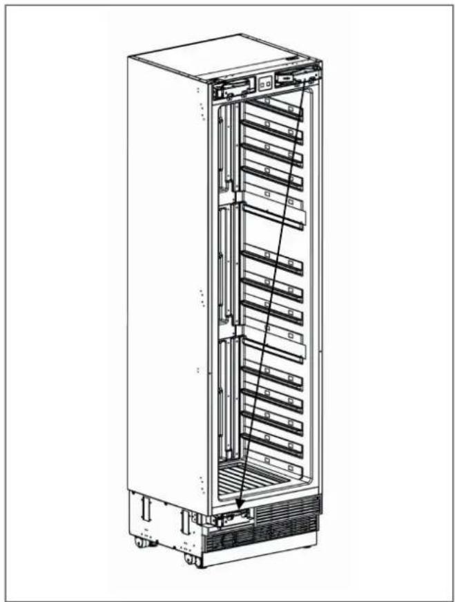
Remove 5 screws to take out the Vent Hole Assembly.

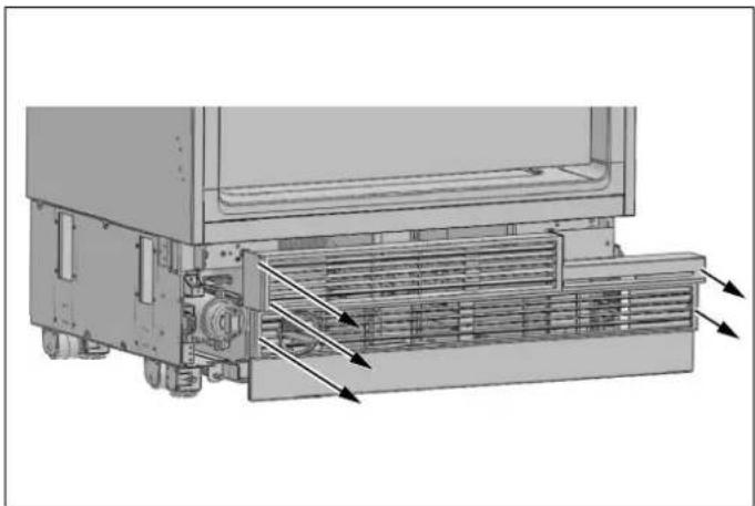
Fig. 13
Fig. 12

CAUTION
Do not remove the tape from the upper door of the appliance until the refrigerator is placed in the cabinet.
Tipping risk.
REVERSING THE DOOR (IF APPLICABLE)
Take out the new hinge brackets from accessories bag and screw them on the reverse side.
We recommend you seek the help of another individual to support the door while you perform this operation.
Depending on the installation position, the opening of the wine cabinet can be switched. If necessary, do so before placing the wine cooler into the cabinet.
- Remove the hinge connection screws from the hinge brackets.
CAUTION
The door will be released when these screws are removed. You must take measures to prevent the door from falling. You can tape the cabinet door to the inner door or ask a second person to help.
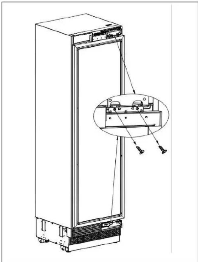

Fig. 15
Fig. 14
Take out door and lay it down on a table.
- Remove the hinge brackets on the fridge door.
- Remove the Hinge Caps located at the other side where you will fix the hinges.
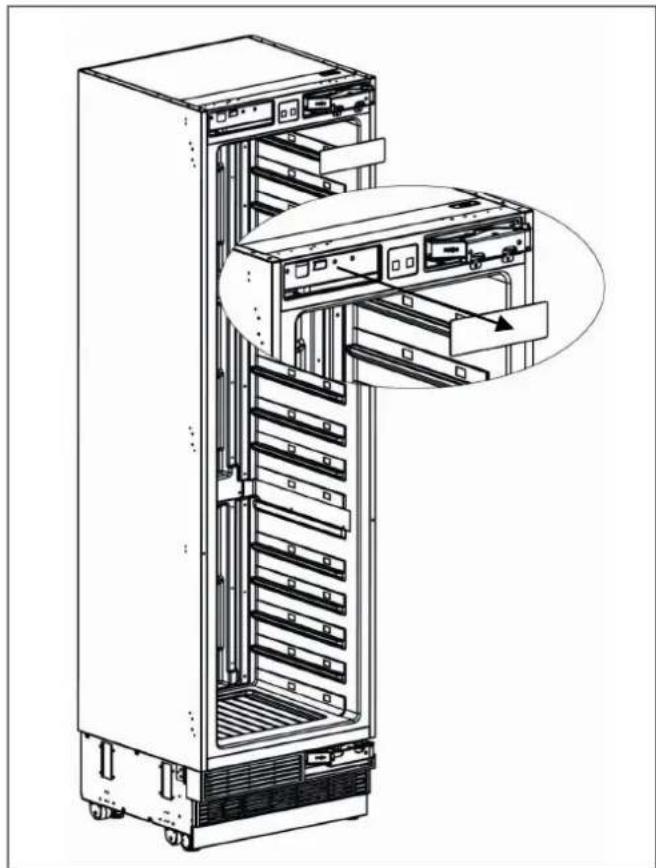
Fig. 16
- Remove the lower right hinge by loosening its 2 screws and fix it to its slot at the upper left side.
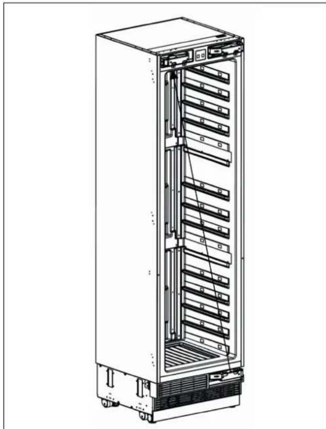
Fig. 17
- Remove the air vent part and change direction as shown figure.
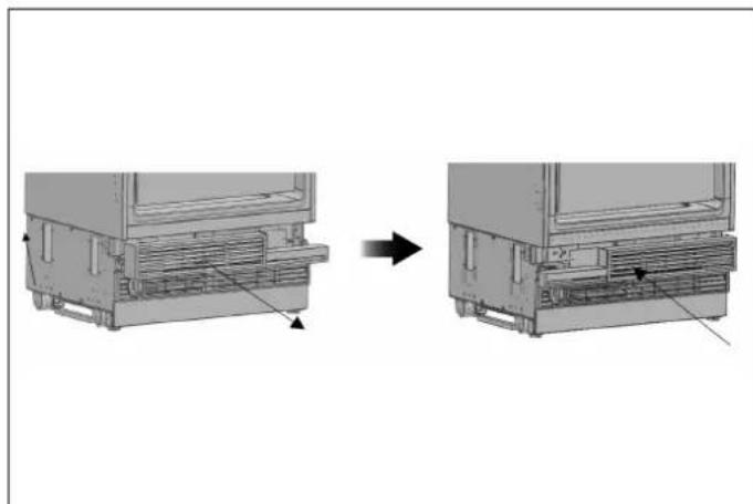
Fig. 18
Air vent upper part for the right hinge
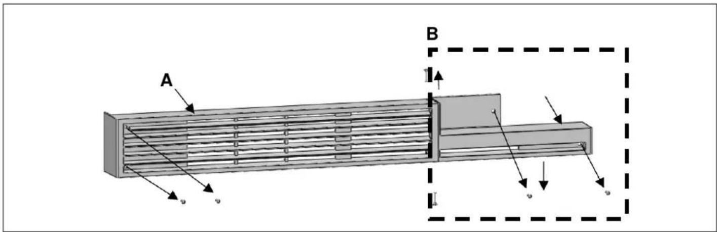
Fig. 19
A Air vent cover
B Air vent hinge part right
Air vent upper part for the left hinge
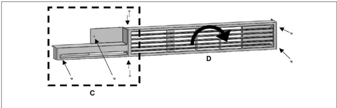
Fig. 20
C Air vent hinge part left
D Rotate air vent cover by 180^
- Remove the upper right hinge by loosening its 2 screws and fix it to its slot at the lower left side.
Attach the Hinge Slot Caps removed from the left side to the Hinge Caps to the right side.
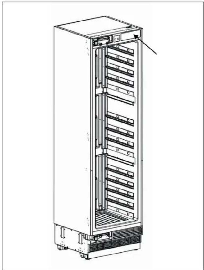
Fig. 22
Fig. 21
- Place the door to the refrigerator and fix it with 4 screws

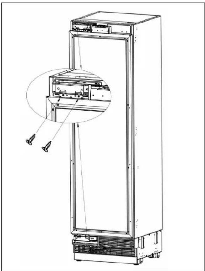
Fig. 23
INSTALLATION INSTRUCTION (DOOR ON DOOR HINGE)
| DESCRIPTION | RWC45S5TPLS / RWC45S5TPRS | RWC60S5TPNS |
| Door handle (if applicable) | 1 | 1 |
| Allen/hex key (if applicable) | 1 | 1 |
| Handle mounting fastener(if applicable) | 2 | 2 |
| Gasket (if applicable) | 2 | 2 |
| Stop nut, M5 (if applicable) | 2 | 2 |
| set screw, M5*10 (if applicable) | 2 | 2 |
| Anti-tip bracket | 2 | 2 |
| Anti tip bracket screws and dowels | 8 | 8 |
| Bracket furniture | 8 | 8 |
| Counter sunk head screw,ST4x14 | 20 20 | |
| Truss washer head,ST4*12 | 16 16 | |
| Position adjustment part | 1 | 1 |
| Countersunk head screws for fixing woodendoors ST4x35 | 8 | 8 |
| Air vent hinge part(if applicable) | \ | 1 |
| 90°limit pin | 2 | 2 |
| Furniture door preparation template | 1 | 1 |
| decorative parts | 1+2+2 1+2+2 | |
| User manual | 1 | 1 |

NOTE
The appliance must be plugged in before installation.
MOUNTING THE ANTI-TIP BRACKETS

WARNING
If the unit cannot be secured to the cabinetry (which in turn must be secured to wall) to prevent tipping, make sure to use the supplied anti-tip brackets in order to prevent the appliance from tipping over.

WARNING
Make sure that there is no electrical or water connection in the adjacent cabinets into which the mounting screws will be screwed to secure the refrigerator.

WARNING
Please remember to use the necessary protective equipment when drilling holes in the wall and performing the installation.
- Use a tape measure to mark the wall for installation of the anti-tip brackets.

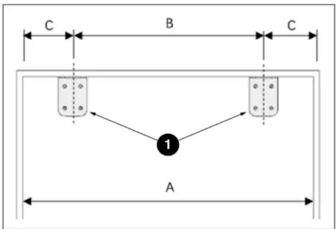
Fig. 24
1 Anti-tip bracket, on the wall
| CATEGORY RWC45S5TPLS / RWC45S5TPRSR RWC60S5TPNS | ||
| A | 457 mm (18") | 609 mm (24") |
| B | 295 mm (11 5/8") | 447 mm (17 5/8") |
| C | 81 mm (3 3/16") | 81 mm (3 3/16") |
- For the most secure installation, use a stud-finder to secure the anti-tip brackets in wall studs. If no studs are present at the correct installation location, follow the instructions below.

WARNING
Always make sure that the area to be drilled into is free of any waterlines or electrical circuits, which could cause damage, injury, or death.
Use a drill to create holes for wall anchors (#2) at the marked points 7.9mm (5 / 16^ 0) 8 mm).

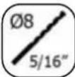

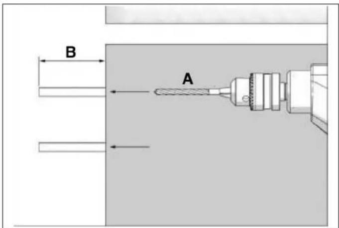
Fig. 25
- Use a hammer to install the wall anchors (#2) if no stud is present.
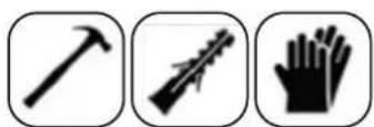
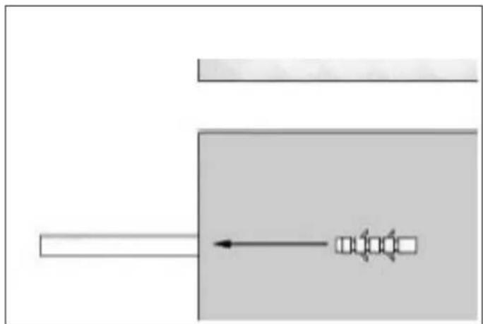
Fig. 26
Install the brackets (#1) in place, using 4 screws for each.
A. 8mm (5/16")
B. >62 ~mm
- You must use both (two) brackets to ensure that the appliance is safely supported.

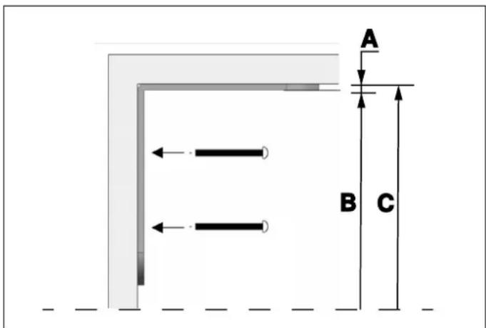
The minimum section dimensions of the wooden support must be 76mm× 102mm(3^ × 4^ ) . The width of the support must be equal to the clearance where it will be installed. This can be achieved using one 102mm× 102 mm (4^ × 4^ ) or two 51mm× 102mm(2^ × 4^ ) pieces of framing lumber.
The calculation of blocking depth is based on a standard niche depth. If the depth of the niche is greater than 610 mm (24"), ensure the blocking overlaps the upper rear fridge body by 51mm (2").
Position the wooden support, mark the location on the rear wall, select suitable screws and mount it securely.

Fig. 27
WARNING
The quantity and type of screws or fasteners to be used for affixing wooden blocking must be suitable for ensuring a secure connection to the rear wall.
A. 4 ~mm(5 / 32^ )
B. 2130 ~mm (83 27/32")
C. 2134 ~mm(84^ )
NOTE
If you are not confident that the supplied connectors and anti-tip brackets are mounted on the wall as securely as they should be, you can use alternative anti-tip methods.
If there is a cabinet panel behind the back wall of the refrigerator, make sure that it is securely fastened to the wall. For this, you need to be sure that the back wall of the cabinet panel is affixed to a wall stud.
Alternative anti-tip method:
If the anti-tip brackets cannot be mounted securely, you must use the alternative method below. For this method, you can use wooden boards to avoid the risk of tipping over.
They must be installed as illustrated in the figure below.
There must be no clearance between the appliance and the wooden support.
INSTALLATION IN THE CABINET
Taking the Refrigerator from the Wooden Pallet
- Remove the brackets which secure the refrigerator to the wooden pallet as shown below.
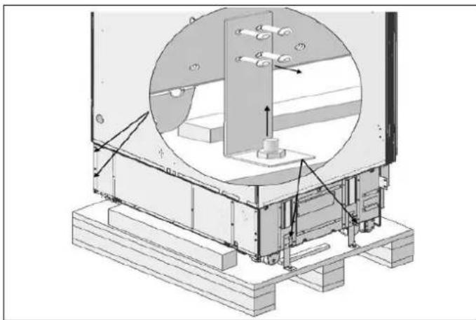
Fig. 28
Slowly tilt the refrigerator back and remove it from the pallet, taking care not to damage the underside of the unit. When transporting the unit, always carry it from the sides to ensure that the unit's feet remain on the base of the appliance dolly.
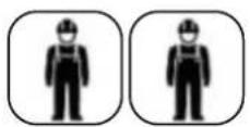
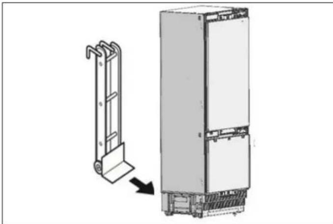
Fig. 29

NOTE
Exercise extreme caution when handling the unit, as the underside of the fridge has components vital to its proper operation; damage to these components could result in a malfunction or potential leakage of condensate and damage to floors.

CAUTION
The risk of tipping over is high from this point forward. You should not open the doors until the product is placed into the cabinet.
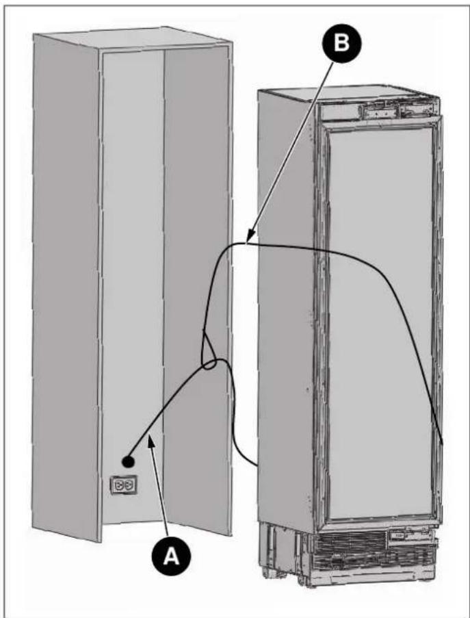
Fig. 30
A Power cord
B Nylon cord
C Move to wall
D Water hose
Connect the electrical plug to the power outlet. Turn on the unit to ensure it has power. (To see if the product is operating, check if the lamps in the freezer compartment are on or off).

NOTE
Protect the front edges of the cabinet niche with masking tape; this will help protect them from damage when pushing the unit back into the niche. Use some packing tape to secure the excess electrical cord to the back of unit to prevent slack from catching under the unit during installation.

NOTE
The unit's plug must be accessible after installation. If the plug is not accessible after installation, the power must have a dedicated circuit breaker which can be accessed to cut power off using the main switch.

WARNING
Make sure that the power cord does not get wedged in when placing the product.
- Push the product carefully towards the cabinet to position it; the unit should slide into the niche with relative ease. If you experience resistance while placing the product in the cabinet:
The floor might be uneven.
The adjustable feet might be loose (please see the relevant section to learn how to adjust the adjustable feet).
You must attach the freezer door temporarily to align the product before placing it.

NOTE
Use the upper edges of the fridge and freezer doors to align the unit in the niche opening.
Adjustment of other edges is explained in the following pages.
SCREWING THE SIDE AND UPPER BRACKETS
Fix the bracket furniture to the unit, where 2 on the top, and 3 on every side.
Use the truss washer head screws(M4*12) to tighten.
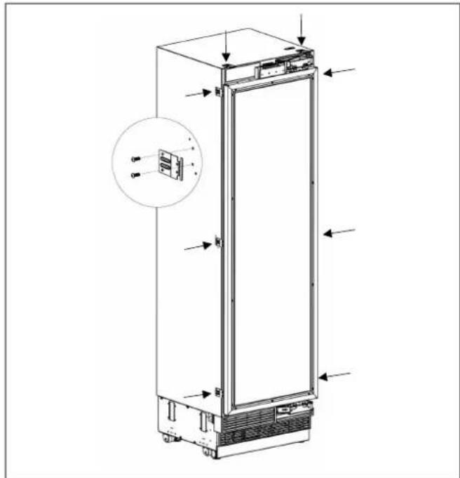
Fig. 31
Push the product carefully towards the cabin to place it.
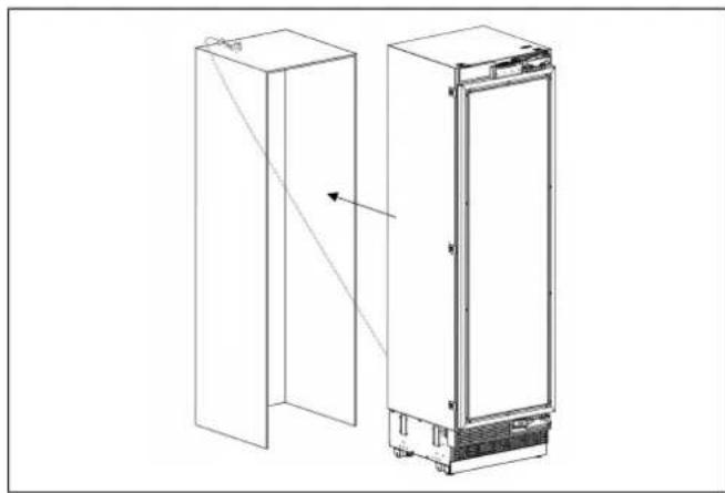
Fig. 32

WARNING
The plug of the product must be accessible after installation
ADJUSTING THE HEIGHT
- Use the adjustable leg mechanism to raise, lower and level the unit in the niche as per the diagram below.

WARNING
Once the unit is pushed into the niche, raise the front feet first; this will reduce the risk of the unit tipping forward during the height adjustment process.
The maximum height that the adjustable feet can reach is 40mm (1 9/16").
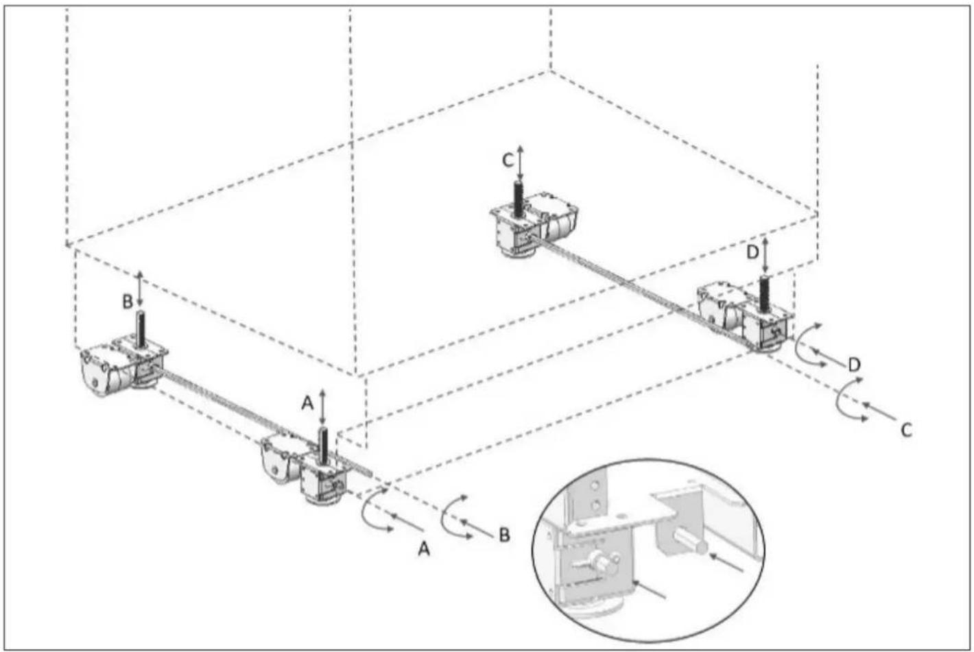
Fig. 33
A/D -Turn the adjusting rod clockwise to lift the front
B/C -Turn the adjusting rod clockwise to lift the rear
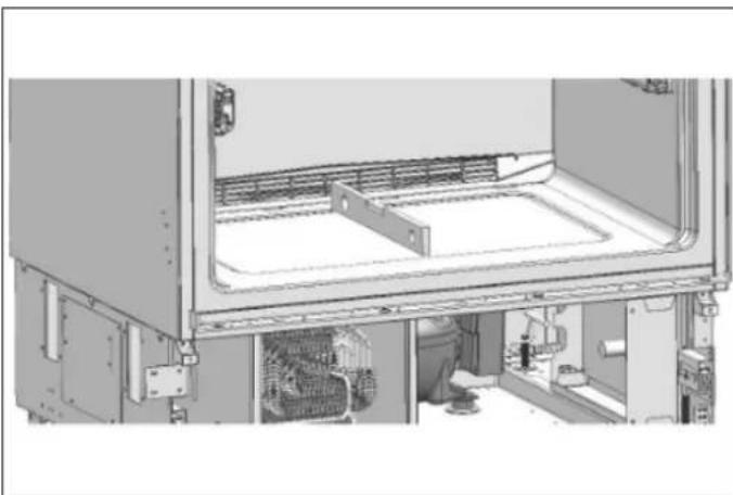
Fig. 34
Ensure the appliance is level.
ADJUSTING THE REFRIGERATOR ACCORDING TO THE CABIN FLANGE
- Attach the bracket furniture to the furniture with 16 screws(M4x14).
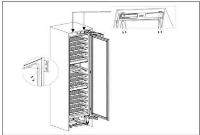
Fig. 35
Position of the adjustment part must be adjusted according to the thickness of the door.
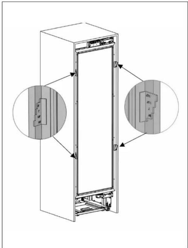
Fig. 36
ATTACHING THE VENT HOLE ASSEMBLY
Use 5 screws to attach the vent hole assembly.
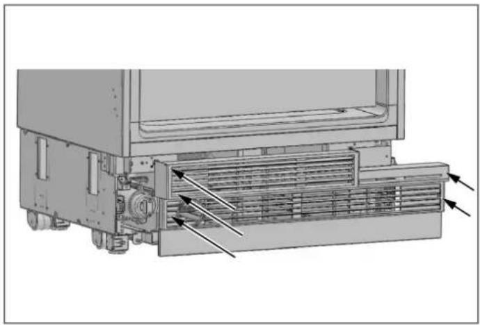
Fig. 37
ATTACHING THE DECORATIVE PARTS
Attach the side closing parts onto the right/left/upper connection brackets.
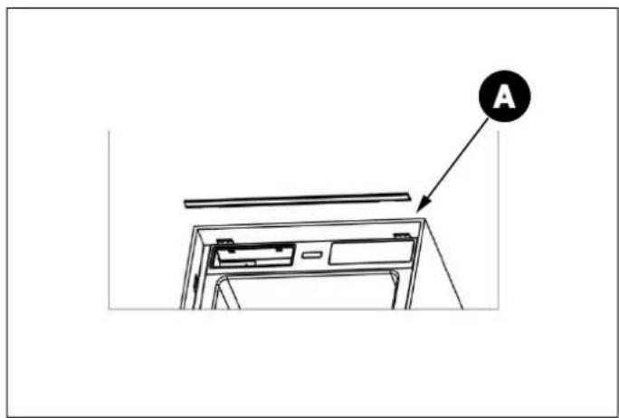
Fig. 38
| CATEGORY A | |
| RWC45S5TPLS / RWC45S5TPRS | 457 mm (18") |
| RWC60S5TPNS | 609 mm (24") |
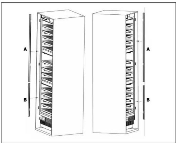
Fig. 39
A. 2159 ~mm (85")
B. 617 ~mm(24^ )
REMOVING THE PANEL-ADJUSTMENT MECHANISMS ON THE REFRIGERATOR
Remove screws to take out the top hanger bracket cover.

WARNING
There is a magnet on the top hanger bracket cover. This is a functional part for the operation of the product. It should not be confused with the low hanger
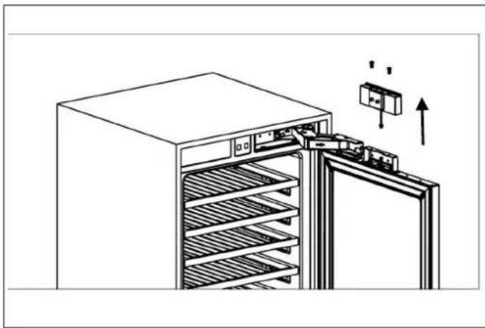
Fig. 40
Remove the upper and lower adjusting mechanism assemblies from the door.
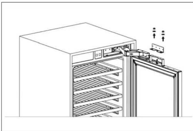
Fig. 41
PREPARING FURNITURE DOOR
When marking, you can use the "Furniture door preparation template" provided with the product.

Fig. 42
Install cradles using the chipboard screws.
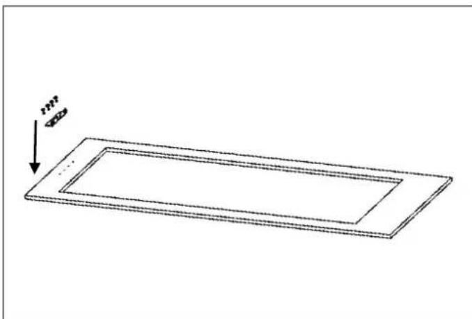
Fig. 43
INSTALLING THE FURNITURE DOOR
Use 2 screws to fix.
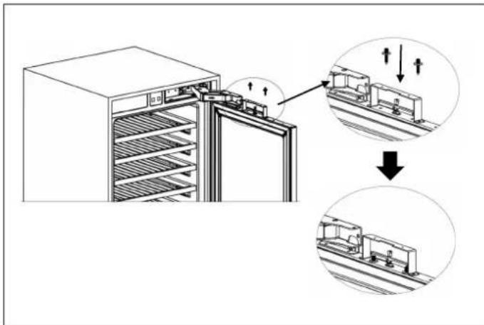
- Attach the furniture door to the door
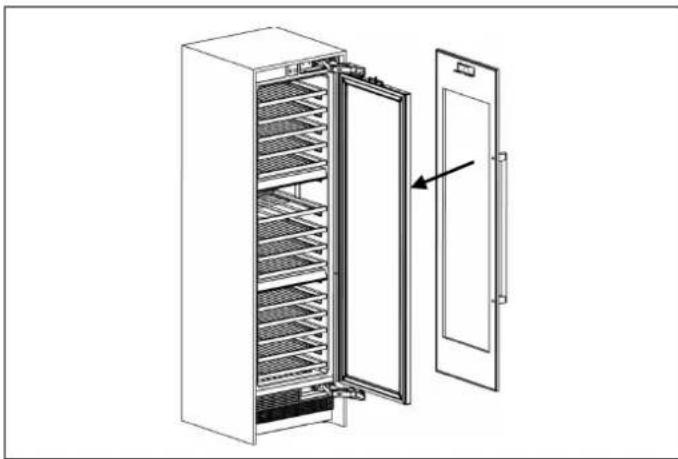
Fig. 45
Fig. 44 You should adjust 3D direction using by two fixing bolt to perform fine adjustments.
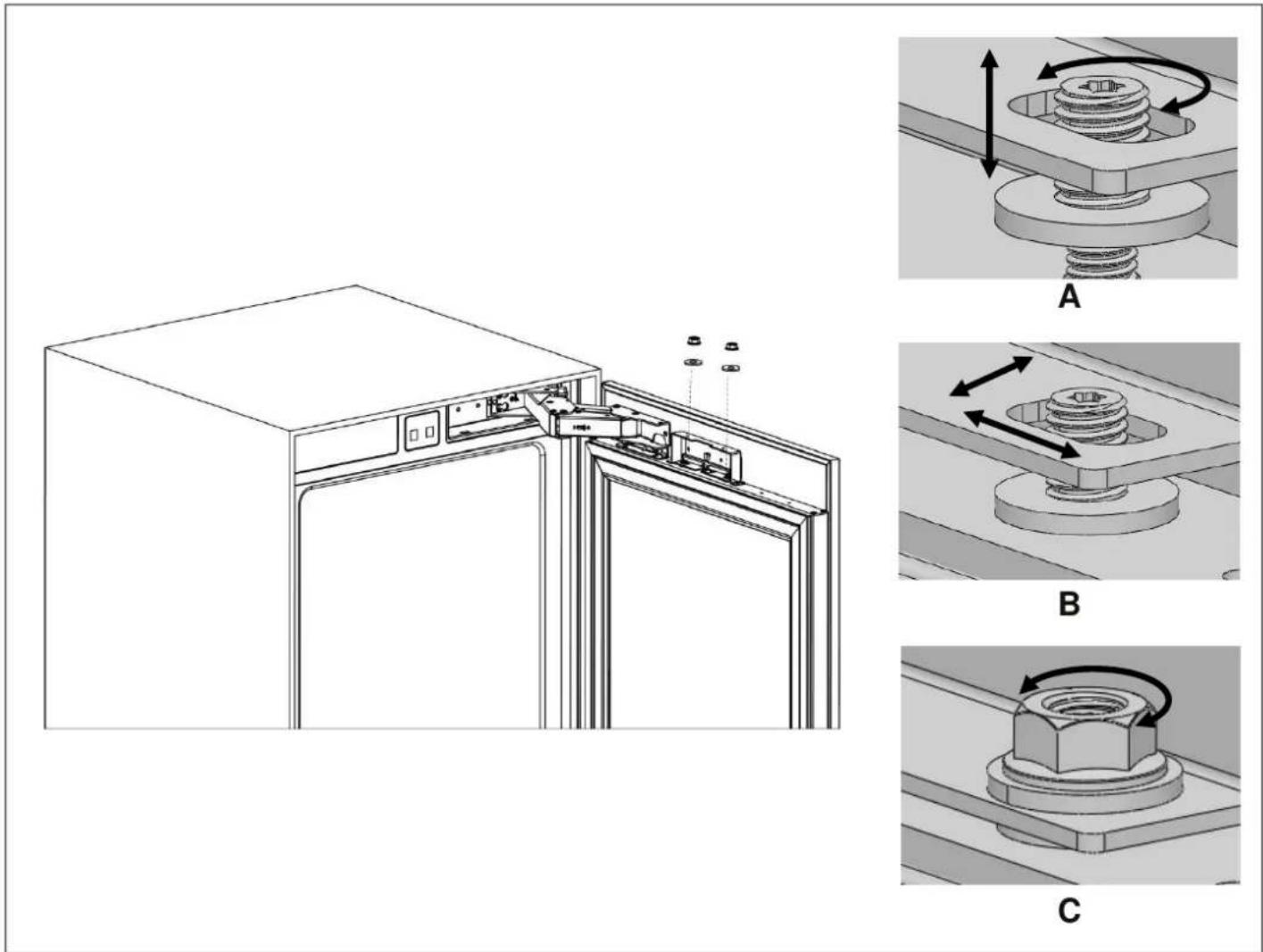
Fig. 46
A. Up & down
B. Front & back / Left & right
C. Fixing furniture door completely
How to align the furniture door upper part with bolts.
- Attach and screw the upper decoration cover.

Fig. 47
The left and right are secured by installing screws (ST4x35).
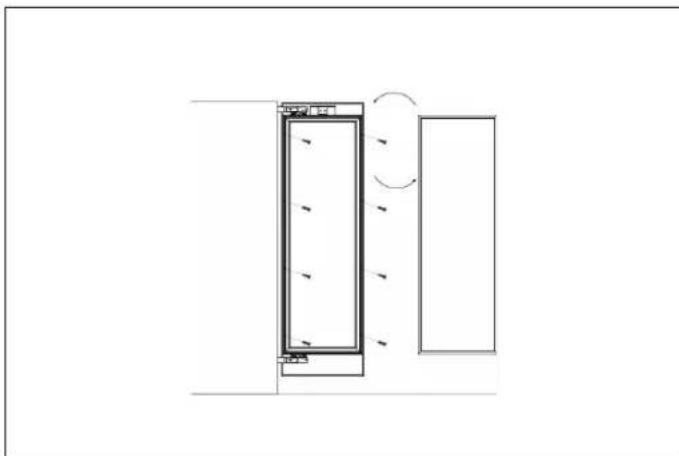
Fig. 48
LIMITING PINS
The refrigerator door can open up to a maximum of 115^
If the door panel thickness exceeds 38mm (11 / 2)^ , the door should not open more than 90^ . In such case, or if the refrigerator is placed next to a wall, a 90^ limit pin should be installed on the upper and lower hinges.
Ensure the pin is fully seated in the bracket; otherwise, the door will not close properly.
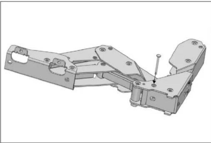
Fig. 49
REMOVING THE SHELVES
1) Pull the wine shelf out of the telescopic glides at the front.
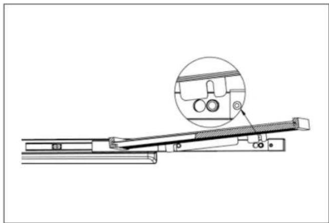
2) Pull the wine shelf forward. The telescopic glides fixing post is locked at the back in the position shown in the figure.

3) Pull up the shelf to remove it.
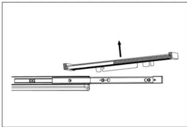
ENSURING THE DOOR SEALS CORRECTLY
It is normal for the seal to be compressed after the door has been reversed. With the door closed, use a hair dryer to expand the seal and fill the gap between the door and the body of the appliance. Take care not to hold the hair dryer too close to the appliance, which could damage the seal.
A distance of approximately 10cm should be suitable. When completed, allow the seal and door to cool before touching them. Once done, the seal should remain in position.
BEFORE FIRST USE
Remove all exterior and interior packaging. Allow the appliance to stand upright for at least 24 hours prior switching the power on.
This will reduce the possibility of a malfunction in the cooling system caused by handling during transportation.
Clean the interior of the refrigerator as recommended in the CLEANING AND CARE section. Before you turn on the appliance, make sure that the interior is dry.
Plug the appliance into a grounded socket. The interior lighting comes on when the door is opened.
- Run the wine column for 6 hours before placing any bottle in it and do not open its door unless it is necessary.

NOTE
You will hear a noise when the compressor starts up. The liquids and gases sealed within the refrigeration system may also cause noise, even if the compressor is not running. This is quite normal.

NOTE
The front edges of the appliance may feel warm. This is normal. These areas are designed to be warm in order to prevent condensation.
During operation, you may hear some absolutely normal noises:
e. Buzzing: The refrigerator is running. The fan of the air.
or to recirculation system is running.
Bubbling, humming or gurgling noises: refrigerant is flowing through the pipes.
- Clicking: motor is turning on or off.
The door on the 60 cm (24") wide wine column appliance can be opened from either the left or the right side. The unit is delivered with the door opening on the left side. Should you wish to open the door from the right, follow the instructions included in this manual in the REVERSING THE DOOR (IF APPLICABLE) section.
If you have received a damaged product, immediately contact the dealer or distributor from which you purchased the product.
Carefully read and follow these instructions for the installation, use and maintenance of the appliance.
Read the troubleshooting section of this manual, which will help you diagnose and solve the most common problems.
INTERNAL STORAGE
This wine column features 3 independent temperature zones, each adjustable from 5 to 20^ (41 to 68^ ).
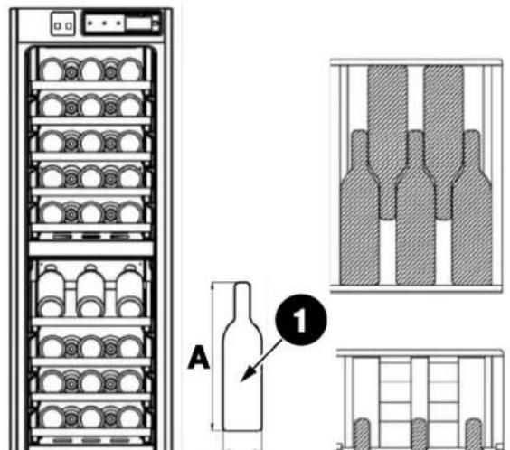
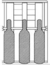
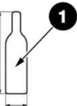
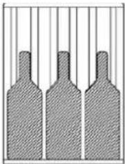
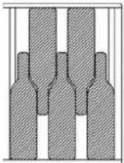
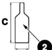
The figures in this section show two different loading patterns. Follow the one best suited to your needs.
The wooden shelves can be removed to increase the load capacity, but make the appliance less practical for everyday use. To remove a shelf, see the REMOVING THE SHELVES paragraph.
The most energy-saving configuration requires the shelves to be installed in the appliance; please see the pictures above.
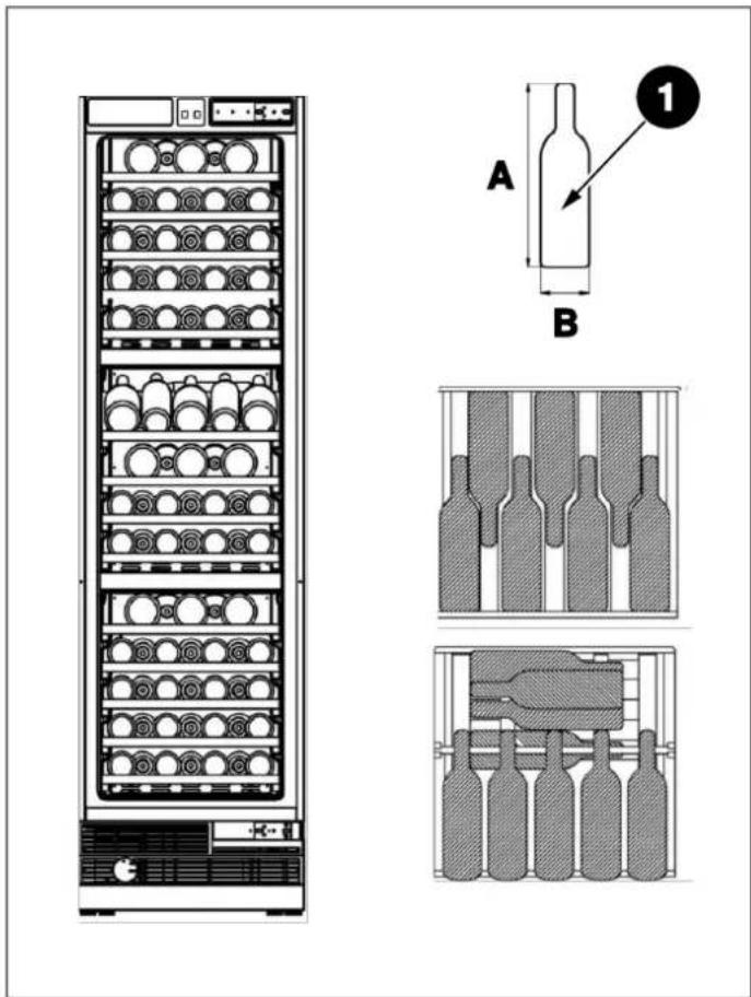
Fig. 50 BOTTLE STORAGE A RWC60S5TPNS
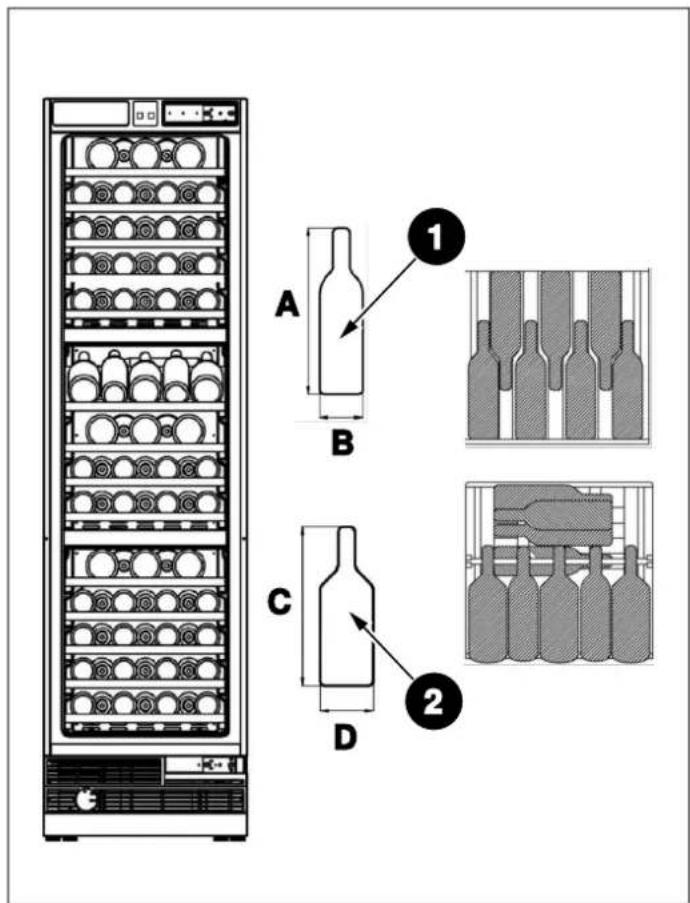
Fig. 51 BOTTLE STORAGE B RWC60S5TPNS
A. 300 mm
C. 300 mm
B. 76 ~mm
D. 96 ~mm
| LOAD CAPACITY RWC60S5TPNS | BOTTLE STORAGE A BOTTLE STORAGE B (BOTTLE 1- BORDEAUX (BOTTLE 1- BORDEAUX (BOTTLE 2- BURGUNDY TYPE) TYPE) TYPE) | ||
| Upper zone | 17\ | 5 | |
| 277\ | |||
| 377\ | |||
| 477\ | |||
| 577\ | |||
| Middle zone | 1963 | ||
| 27\ | 5 | ||
| 377\ | |||
| 477\ | |||
| Lower zone | 17\5 | ||
| 277\ | |||
| 377\ | |||
| 477\ | |||
| 577\ | |||
| Total 100 76 18 | |||
B
1
1
B
D
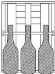
Fig. 52 BOTTLE STORAGE A RWC45S5TPLS / RWC45S5TPRS
Fig. 53 BOTTLE STORAGE B RWC45S5TPLS / RWC45S5TPRS
A. 300 mm
C. 300 mm
B. 76 mm
D. 96 ~mm
| LOAD CAPACITY RWC45S5TPLS / RWC45S5TPRS | BOTTLE STORAGE A BOTTLE STORAGE B | |||
| (BOTTLE 1- BORDEAUX (BOTTLE 1 - BORDEAUX(BOTTLE 2 - BURGUNDY TYPE) TYPE) | ||||
| Upper zone | 1 | 5 | \ | 3 |
| 2 | 5 | 5 | \ | |
| 3 | 5 | 5 | \ | |
| 4 | 5 | 5 | \ | |
| 5 5 5 | \ | |||
| Middle zone | 1 3 \ 3 | |||
| 2 | 5 | \ | 3 | |
| 3 | 5 | 5 | \ | |
| 4 | 5 | 5 | \ | |
| Lower zone | 1 | 5 | \ | 3 |
| 2 | 5 | 5 | \ | |
| 3 5 5 | \ | |||
| 4 5 5\ | ||||
| 5 5 5 | \ | |||
| Total 68 50 12 | ||||
CARBON FILTER
Three built-in carbon filters serve as a natural barrier against harmful odors, ensuring the protection of your beverages.
To maintain optimal performance, it is recommended to replace the carbon filter every 3 to 6 months, depending on the unit's exposure to odors.
If the unit is situated in a kitchen, replacing the filter every three months is ideal.
To remove the carbon filter, simply turn it counterclockwise to unlock it from the rear panel.
Replacement filters can be ordered from your dealer of choice.
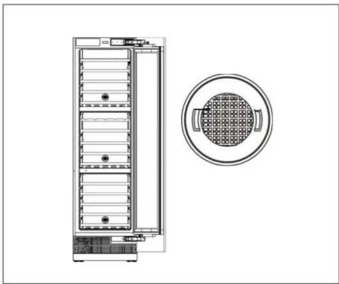
Fig. 54
RECOMMENDATIONS FOR STORING AND SERVING WINE
To best appreciate the organoleptic qualities of each wine, it is necessary that storage and consumption be carried out at certain temperatures.
The following table summarises the most suitable storage temperature for each type of wine. It is recommended, particularly for more valuable bottles, to appropriately follow the instructions provided by the producer.
| TYPE OF WINE STORAGE TEMPERATURE (°C°C) | |
| Young and light white wines | 10 - 12 |
| Mature and structured white wines | 12 - 14 |
| Aromatic white wines 8 - 10 | |
| Young and light rosé wines | 10 - 12 |
| Mature, full-bodied rosé wines | 12 - 14 |
| Young red wines | 10 - 14 |
| Young, slightly tannic and light red wines | 14 - 16 |
| Mature, tannic and full-bodied red wines | 16 - 18 |
| Very mature, tannic and full-bodied red wines | 16 - 18 |
| Sweet and aromatic sparkling wines | 8 - 10 |
| Sweet and aromatic red sparkling wines | 10 - 12 |
| Charmat method sparkling wines | 8 - 10 |
| Long Charmat method sparkling wines | 10 - 12 |
| Classic method sparkling wines | 8 - 10 |
| Classic “Millesimato” method sparkling wines | 10 - 12 |
| Dry and semi-dry sparkling wines | 8 - 10 |
| Semi-sparkling wines | 10 - 12 |
| Superior sweet sparkling wines | 10 - 12 |
| Fortified, dessert or straw wines | 10 - 18 |
WHITE WINES
White wines are normally not served at high temperatures, since they are generally more acidic that red wines and not very tannic, which is why they are more enjoyable at low temperatures.
These wines should preferably be stored and served between 10^ and 14^ (50°F and 57°F). Young, fresh and aromatic wines can also be served at 10^ (50°F), while less aromatic ones are recommended at 12^ (54°F). Temperatures between 12^ and 14^ (54°F and 57°F) are suitable for soft, mature white wines aged for a few years in the bottle. Higher temperatures would favour the enhancement of the sweet character of the wine, to the detriment of the acidity and flavour that are considered pleasant and desirable characteristics for this type of wine.
ROSE WINES
Rose wines are generally served at the same temperature as white wines. However, it should be noted that these wines may contain a certain amount of tannins and it may therefore be preferable to taste them at higher temperatures so as not to make them too astringent. Consequently, they are served between 10 and 12^ (50 and 54^ ) if young and fresh and between 12 and 14^ (54 and 57^ ) if more robust and mature.
RED WINES
Containing more tannins and being less acidic, red wines are usually served at higher temperatures.
Younger and less tannic wines are generally served between 14 and 16^ (57 and 61^ ), while fuller-bodied and tannic wines can be served at 16^ ( 64^ ), and exceptionally even at 18^ ( 64^ ). Some wines aged for years in the bottle, still full-bodied and tannic, can be served at 18^ ( 64^ ) or even at 20^ ( 68^ ). Young red wines that are low in tannins and less structured can be enjoyed at lower temperatures, between 12 and 14^ ( 54 and 57^ ).
CLASSIC OR CHARMAT METHOD SPARKLING WINES
Given the high variety of existing sparkling wines, it is difficult to give valid recommendations for all.
In general, sweeter and more aromatic sparkling wines should be served at lower temperatures, up to 8^ (46^) due to their aromaticity. More tannic sparkling wines can be served at higher temperatures, up to 14^ (57^) .
Dry Charmat or Martinotti method sparkling wines, such as some Proseccos, should generally be served between 8 and 10^ (46 and 50^ ). Classic method sparkling wines and 'methode Champenoise' such as Champagne are also normally served at these temperatures but, for sparkling wines aged for some time such as Millesimati, one can go up to 12^ (54 F) to favour the development of complex aromas.
However, it is advisable, especially for the finest wines, to follow the producer's recommendations, which are printed on the bottle.
SPARKLING WINES
For semi-sparkling wines, the same temperature indications apply as for Classic or Charmat method sparkling wines and are generally served between 10 and 12^ (50 and 54^ ). For dry and semi-dry sparkling wines, a slightly lower serving temperature of between 8 and 10^ (46 and 50^ ) is recommended.
FORTIFIED, DESSERT OR STRAW WINES
This type of wine can be served at temperatures between 14 and 18^ (61 and 64^ ) depending on personal taste and, to attenuate the sweet taste and high alcohol content, it can also be served at 10^ ( 50^ ).
Dry liqueur wines, such as Marsala for example, contain so much sugar that they are not perceived on the palate. For these wines, the serving temperature should be set according to what you want to emphasise. If you prefer to accentuate the sweetness of the wine, the complexity of its bouquet and its austerity, it is best to serve it at a high temperature, between 14^ and 18^ (61 and 64^ ), remembering that this will also enhance the alcohol component. If you want to enhance their freshness more, they should be served at a lower temperature of between 10^ and 14^ (50 and 61^ ). Dry, fresh, young liqueur wines can also be served at a cooler temperature of less than 10^ ( 50^ ) in order to significantly reduce the perception of alcohol. However, the lower the serving temperature, the lower the perception of aromas will be. The pleasantness and complexity of aromas typical of these wines is a welcome and interesting characteristic: serving them too cold means sacrificing this important aspect.
CONTROL PANEL
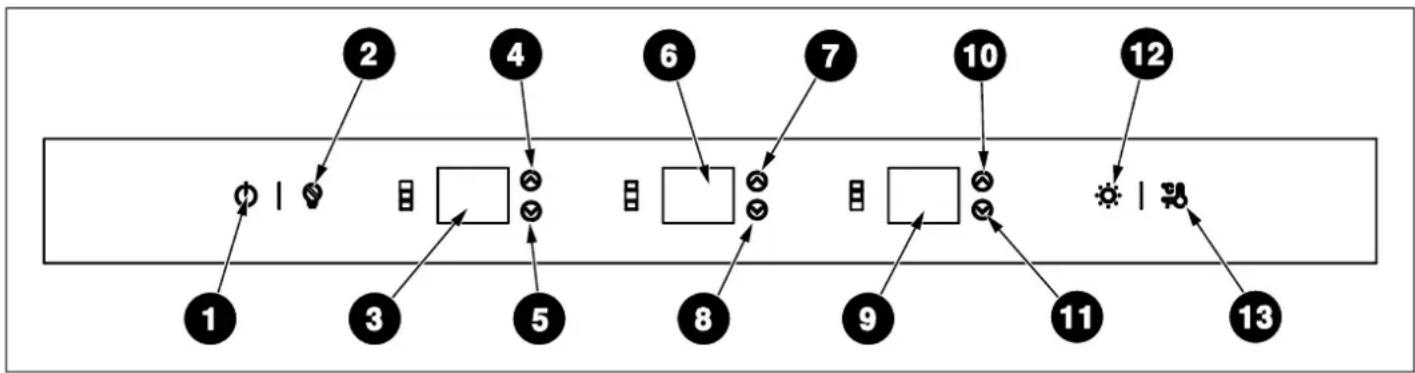
Fig. 55
1) On/Off Button
2) Sabbath Mode
3) Upper Zone Temperature
4) Upper Zone Temperature Increase Button
5) Upper Zone Temperature Decrease Button
6) Middle Zone Temperature
7) Middle Zone Temperature Increase Button
ON/OFF BUTTON
Serves to switch the whole appliance On or Off. Press [1] for 3 seconds to switch the appliance on/off. When switched off, the appliance disconnects from all external power sources and switches to standby status.
ENABLING/DISABLING THE CHILD LOCK
The child lock is a feature for preventing children from changing the appliance's settings. Press buttons [12] + [13] simultaneously to lock/unlock the control panel.
When the child lock is enabled, the temperature values in the digital displays will flash simultaneously for 3 seconds, accompanied by an acoustic signal to indicate that the display is locked. Deactivate the child lock to change any settings.
8) Middle Zone Temperature Decrease Button
9) Lower Zone Temperature
10) Lower Zone Temperature Increase Button
11) Lower Zone Temperature Decrease Button
12) Light Button
13) Celsius and Fahrenheit Selection
TEMPERATURE ADJUSTMENT BUTTONS
Press buttons [4], [7], [10] to increase the temperature value by 1 degree with each press. Press buttons [5], [8], [11] to decrease the temperature value by 1 degree with each press. The temperature can be set from 5^ (41^) to 20^ (68^) in each temperature zone.

NOTE
When changing the temperature of the three zones, the displays will immediately show the selected temperatures on of the three zones. The actual temperatures inside the zones will gradually change until the desired set temperatures are reached. The appliance will take some time to reach the new set temperatures; this is normal.
LIGHT COLOR SELECTION, LIGHT BRIGHTNESS SELECTION AND ENTERTAINMENT MODE
The switching on/off of the LED lights depends on the door opening/closing. When the door is opened, the lights switch on automatically. When the door is closed, the lights switch off to save energy.
For selecting the light color, press button [12] to change the color of the LED illumination between amber, blue or white.
Press the [12] button for 3 seconds to activate the entertainment mode and keep the light constantly on even when the door is closed. The displays of the three temperature zones will show 'ON' for 5 seconds. After 5 seconds, the digital displays will show again the set temperatures in the 3 zones.
To adjust the brightness of the lights, press [12] until all digital displays of the three temperature zones show "ON". Within 5 seconds, press [4], [5], [7], [8], [10], [11] to adjust the brightness of the LED lights among seven levels, in brightness increments from L1 to L7.
CELSIUS AND FAHRENHEIT SELECTION
To switch between Celsius and Fahrenheit, press button [13]. Each press makes a switch. Celsius is set as the factory default.
SHOWROOM MODE
Press [1] + [2] buttons simultaneously for 3 seconds to enable the function.
This mode is used when the refrigerator is on display in a retail store or if you want to turn the cooling off and deactivate all other functions except interior lighting. When enabled, the digital displays of the 3 temperature zones will all show "Sn". If no button is pressed for 72 hours, the mode will deactivate automatically. Press [1] + [2] simultaneously to deactivate the showroom mode at any time.

NOTE
Do not store any item while in showroom mode, because the appliance then remains at room temperature.
SHABBAT MODE
Press [2] to enable/disable the function. When the Shabbat Mode function is enabled, all lights, buzzers and digital displays will be switched off. The compressor and fan will continue to operate normally. The mode is automatically deactivated after 96 hours of operation. If the device is switched off, the status is maintained. Press [2] to deactivate Sabbath mode at any time.

NOTE
When you adjust the temperature on the control panel, it will display the current temperature. The reading will gradually change to reflect the internal temperature until it aligns with your desired setting. Please note that it may take some time for the wine cellar to reach the new temperature, which is entirely normal. You do not need to adjust the desired temperature simply because the display is not immediately showing your preference.
If there is moisture or liquid on the control panel, it may not function properly. Please wipe the surface with a dry cloth and try again.
POWER FAILURE MEMORY FUNCTION
TEMPERATURE RANGES:
Upper Zone: 5-20°C (41°F - 68°F)
Middle Zone: 5-20°C (41°F - 68°F)
Lower Zone: 5 - 20^ (41^ - 68^)

WARNING
Always disconnect the appliance from the mains power before performing any cleaning or maintenance.
LED LIGHT REPLACEMENT INSTRUCTIONS
To provide optimum interior lighting, LED strips illuminate the appliance from the top and sets of LED lights directly illuminate different areas.
In case of malfunction and/or wearing out of the lighting system, repairs should be carried out by a qualified Service technician.
CLEANING THE INTERIOR SURFACES
To clean the inside of the wine column, open the door and remove the shelves. Wipe the inside of the unit with a clean cloth and a mild detergent, or with a soft sponge and a solution of bicarbonate of soda and lukewarm water. Do not use abrasive products or detergents. After washing, rinse and dry thoroughly.
Clean the wooden shelves with a soft, slightly damp cloth. Avoid using soaps, detergents and/or sponges that can damage both wooden and steel surfaces. Dry the shelves carefully before placing them back in the wine column.

WARNING
Do not use vinegar, rubbing alcohol or any alcohol-based cleaning agent on any of the interior surfaces.
If the appliance is not going to be used for an extended period of time, unplug and clean the appliance. The doors should be left slightly ajar to prevent the formation of mildew and unpleasant odours.
CLEANING THE EXTERIOR SURFACES
To clean the door and cabinet, use a mild detergent solution composed of two tablespoons of baking soda per quart of lukewarm water. Refrain from using abrasive or corrosive cleaning agents.
Avoid using solvent-based or abrasive cleaners. Use a soft sponge for cleaning, rinse with clean water, and dry with a soft towel to prevent water spots.
If the door panel is stainless steel, be aware that exposure to chlorine gas and moisture may cause discoloration. Clean the stainless steel with a cloth dampened in a mild detergent and warm water solution.
Refrain from using abrasive or corrosive cleaning agents.
DEFROSTING
The wine column is designed with an automatic defrost system. However, on colder settings, some frost may build up. Additionally, the more humid the ambient conditions, the more frost may build up. Keep the door closed as much as possible and avoid opening the door unnecessarily to minimize frost build-up.
If frost is preventing the door from closing properly, you may need to power the unit off until the frost melts (possibly up to 24 hours). Use a soft absorbent towel to dry the unit.

WARNING
Do not harm refrigerant tubing.
NOISES AND MEANING
This wine column may emit some normal sounds during operation.
Hard surfaces such as the floor or walls may make the sounds seem louder than they actually are.
In the list below you will find the most common sounds and their causes:
- rattling: due to the flow of refrigerant or objects placed on top of the appliance.
- loud or high-pitched sounds: the high-efficiency compressor may emit sounds due to normal operation.
- splashing sound: due to water flowing from the evaporator to the water container.
gurgling sound: refrigerant flowing into the appliance. - air noise: air can be heard being pushed over the condenser by the condenser fan.
POWER FAILURE
Most power failures are resolved within a few hours and should not affect the temperature of the appliance if the number of times the door is opened is minimised. If the power outage continues for a longer period of time, appropriate measures must be taken to protect the contents of your appliance.
If you have any problems with your appliance, please check this troubleshooting section prior to calling Customer Care.
If the appliance is not working, check that:
The appliance is receiving electrical power.
The fuses in the home are intact and the fuse in the plug has not blown.
The appliance has not been turned off.
- The electrical outlet is functioning properly. To check this, plug another electrical appliance into it to see if the outlet is faulty.
If the appliance is working, but not very well, check that:
The appliance is not overloaded.
The thermostat is set to an appropriate temperature.
The doors are closing properly.
The cooling system on the back of the appliance is clean and free of dust and is not touching the rear wall.
There is enough ventilation around the side and rear walls.
If the appliance is not cold enough, check that:
Temperature is not set too high.
The appliance is not installed next to a heat source.
The door is not opened too frequently or for long periods of time.
The door gasket seals properly.
The appliance is not set on demo mode.
- The appliance has sufficient ventilation and ensure it is installed according to the installation requirements specified in this manual.
If the appliance is noisy or turns on and off frequently, check that:
The appliance is level and stable.
The shelves are positioned correctly inside the appliance.
The room temperature is hotter than normal.
The door gasket is properly sealed.
The door is not opened too frequently or for long periods of time.
- The appliance has sufficient ventilation and ensure it is installed according to the installation requirements specified in this manual.

NOTE
The coolant gas in the refrigerator may make a slight bubbling or gurgling noise, even when the compressor is not running.

NOTE
Some popping or cracking noises are normal. They are caused by expansion and contraction of the inside walls due to temperature changes.
If the appliance is beeping, check that:
The doors are closed. An alarm will sound after a door has been open for 60 seconds.
If frost has formed in the appliance:
The environment is too humid.
The room temperature is too low.
The door is being opened too frequently.
- The unit has an auto-defrost system but, under certain conditions, manual defrosting may be required. If frost periodically forms, try to run the refrigerator at a warmer temperature setting, minimising the number of door openings or unplugging the unit to allow the frost to melt.
- Check the door seal for any kinks, debris or damage. If you notice any, and are unable to resolve the issue yourself, contact Customer Care so that the seal can be replaced.
- This can be due to the cabinet door(s) not being properly fitted. If you are at all unsure, ask your installer to check the cabinet doors.
If one or more of the LED units inside the appliance not working:
- Contact Customer Care to arrange a service visit.
If the body of the appliance is electrified:
The unit is not properly grounded. Contact your electrician to test your electrical grounding system.
When a malfunction occurs, contact a service technician for repairs
| EXPLANATION OPEN CIRCUIT CODE SHORT CIRCUIT CODE | ||
| Upper Zone In-cabinet probes | E1 E2 | |
| Upper Zone Frosting probe | E3 E4 | |
| Middle Zone In-cabinet probe | E5 | E6 |
| Middle Zone Frosting probe | E7 E8 | |
| Upper Zone In-cabinet probes | E9 E10 | |
| Lower Zone Frosting probe | E11 E12 | |

NOTE
1) In the presence of a fault code, the buzzer will sound an alarm 'Tic' 'Tic' 'Tic' three times in a row. The fault code will flash on the display every 10 seconds, and the alarm will activate.
If you want to release the alarm sound, press the on/off key.
2) Whenever a key is pressed, the buzzer sounds "Tic".

Bertazzoni is committed to providing the highest quality service to our customers. In the unlikely event that your product should have a manufacturing defect, please contact our service team at:
https://uk.bertazzoni.com/more/care-service
You will be requested to provide product information, proof of purchase, a photo of the silver data label and a description of the issue. Please have this information ready.
DALLA SCRIVANIA DEL PRESIDENTE
Gentile Cliente,
TEMPERATURE ADJUSTMENT BUTTONS
PREPARATION POUR L'INSTALLATION 125
DIMENSIONS DU MEUBLE 126
DIMENSIONS DU PRODUIT 128
PANNEAU DE PORTE PERSONNALISÉ 129
EMPLACEMENT DE LA BRIDE ANTIBASCULEMENT 130
EXIGENCES ÉLECTRIQUES 131
VENTILATION 133
LISTEDESOUTILS 133
DEBALLAGE 134
RETRAIT DE L'ENSEMBLE ÉVENTS D'AÉRATION 135
INVERSION DU BATTEMENT DE LA PORTE (LE CAS ÉCHEANT) 135
INSTRUCTION D'INSTALLATION (PORTE SUR CHARNIÈRE DE PORTE) 141
MONTAGE DES SUPPORTS ANTI-BASCULEMENT 142
INSTALLATION DANS L'ARMOIRE 146
VISSAGE DES SUPPORTS LATERAUX ET SUPERIEURS 148
RéGLAGE DE LA HAUTEUR 148
RéGLAGE DU RÉFRIGÉRATEUR EN FONCTION DE LA BRIDE DE L'ARMOIRE 150
FIXATION DE L'ENSEMBLE DU TROU D'AERATION 151
FIXATION DES ÉLÉMENTS DÉCORATIFS 151
RETRAIT DES MÉCANISMES DE RÉGLAGE DU PANNEAU DU RÉFRIGÉRATEUR 152
PREPARATION DE LA PORTE DU MEUBLE 152
INSTALLATION DE LA PORTE DU MEUBLE 153
GOUPILES DE BUTEE 155
RETRAIT DES ETAGERES 156
ASSURER LA BONNE ETANCHÉITE DE LA PORTE 156
UTILISATION 157
AVANT LA PREMIÈRE UTILISATION 157
ENTREPOSAGE INTERNE 158
FILTRE A CHARBON 162
RECOMMANDATIONS POUR LA CONSERVATION ET LE SERVICE DU VIN 163
PANNEAU DE COMMANDE 166
PRECAUTIONS ET MAINTENANCE 169
INSTRUCTIONS DE REMPLACEMENT DE L'ÉCLAIRAGE À LED 169
NETTOYAGE DES SURFACES INTÉRIEURES 169
NETTOYAGE DES SURFACES EXTERIEURES 169
DECONGÉLATION 169
BRUITSETSIGNIFICATION 170
PANNE DE COURANT 170
RÉSOLUTION DE PROBLEMES 171
CODES D'ERREUR 172
GARANTIE ET ASSISTANCE 173
MANUEL D'UTILISATION
RISQUE DE SUFFOCATION
DIMENSIONS DU MEUBLE
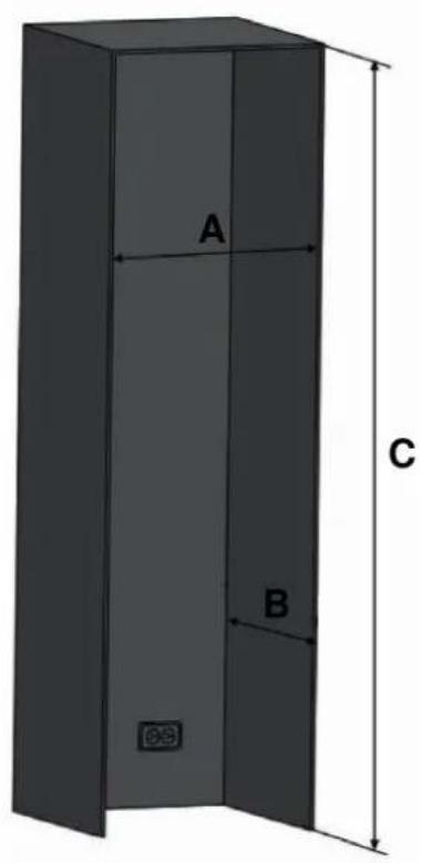
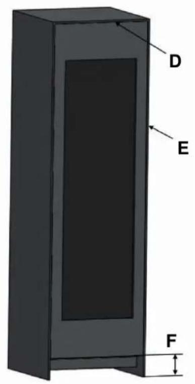
Fig. 2
| CATÉGORIE | RWC45S5TPLS / RWC45S5TPRS | RWC60S5TPNS |
| A | 457 mm (18") 609 mm (24") | |
| B | 635 mm (25") 635 mm (25") | |
| C | de série 2134 mm (84") | de série 2134 mm (84") |
| minimum 2127 mm (83 3/4") | minimum 2127 mm (83 3/4") | |
| maximum 2167 mm (85 5/16") | maximum 2167 mm (85 5/16") | |
| D | 3 mm (1/8") 3 mm (1/8") | |
| E | 3 mm (1/8") 3 mm (1/8") | |
| F | de série 101 mm (4") | de série 101 mm (4") |
| minimum 95 mm (3 3/4") | minimum 95 mm (3 3/4") | |
| maximum 135 mm (5 5/16") | maximum 135 mm (5 5/16") |
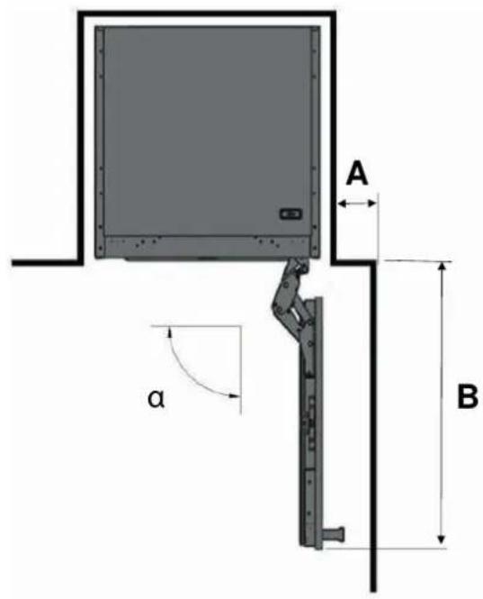
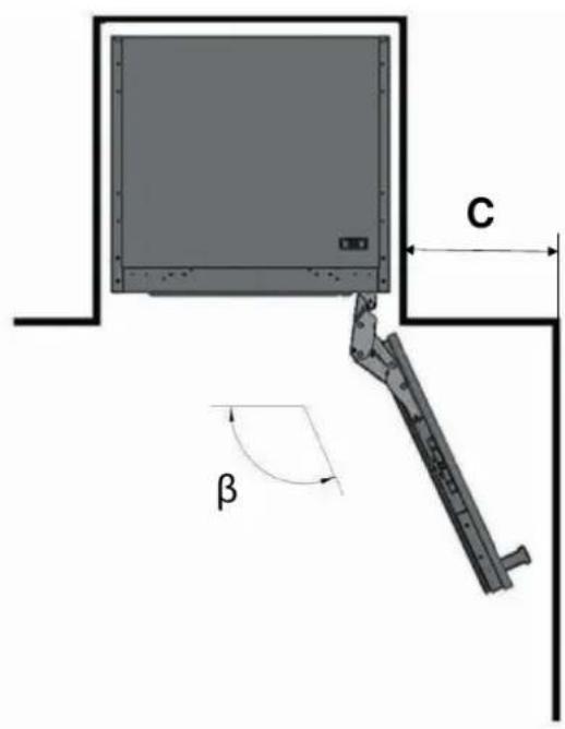
Fig. 3
a 90°
β 115°
| CATÉGORIE | RWC45S5TPLS / RWC45S5TPRS RWC60S5TPNS |
| A | 111 mm (4 3/8" 111 mm (4 3/8") |
| B | 508 mm (20") 660 mm (26") |
| C | 280 mm (11") 356 mm (14") |
DIMENSIONS DU PRODUIT
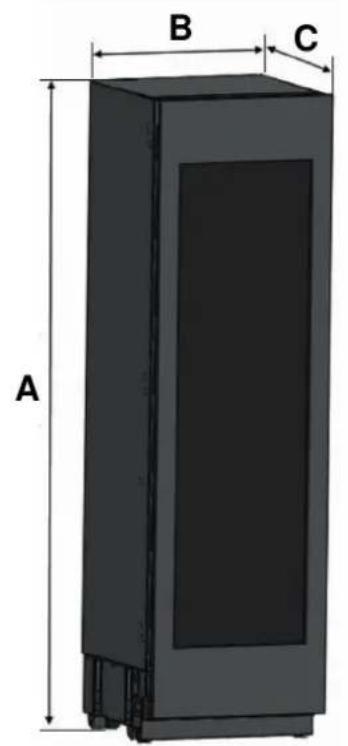
Fig. 4
BOUTON MARCHE/ARRET (ON/OFF)
HET APPARAAT VERPLAATSEN
BESCHRIJVING VAN HET APPARAAT
Afb. 1
https://SE.bertazzoni.com/more/care-service
- FROM THE DESK OF OUR PRESIDENT
- MANUAL VALIDITY
- MANUAL INFORMATION
- DANGER
- WARNING
- CAUTION
- NOTE
- SAFETY INFORMATION
- AVOIDING PLACING CHILDREN AND VULNERABLE PEOPLE AT RISK
- RISK OF ELECTRIC SHOCK
- RISK OF EXPLOSION
- RISK OF INJURY
- RISK OF SUFFOCATION
- RISK OF FOOD POISONING
- FIRE HAZARD / ISOBUTANE WARNING
- CARING FOR THE ENVIRONMENT
- CONFORMITY
- ENERGY SAVING
- MOVING THE APPLIANCE
- ROOM TEMPERATURE
- PREPARING FOR INSTALLATION
- CABINET DIMENSIONS
- ELECTRICAL REQUIREMENTS
- IMPORTANT
- VENTILATION
- TOOL LIST
- UNPACKING
- REMOVING THE VENT HOLE ASSEMBLY
- REVERSING THE DOOR (IF APPLICABLE)
- MOUNTING THE ANTI-TIP BRACKETS
- Alternative anti-tip method:
- INSTALLATION IN THE CABINET
- SCREWING THE SIDE AND UPPER BRACKETS
- ADJUSTING THE HEIGHT
- ADJUSTING THE REFRIGERATOR ACCORDING TO THE CABIN FLANGE
- ATTACHING THE VENT HOLE ASSEMBLY
- ATTACHING THE DECORATIVE PARTS
- REMOVING THE PANEL-ADJUSTMENT MECHANISMS ON THE REFRIGERATOR
- PREPARING FURNITURE DOOR
- INSTALLING THE FURNITURE DOOR
- LIMITING PINS
- REMOVING THE SHELVES
- ENSURING THE DOOR SEALS CORRECTLY
- BEFORE FIRST USE
- INTERNAL STORAGE
- CARBON FILTER
- RECOMMENDATIONS FOR STORING AND SERVING WINE
- WHITE WINES
- ROSE WINES
- RED WINES
- CLASSIC OR CHARMAT METHOD SPARKLING WINES
- SPARKLING WINES
- FORTIFIED, DESSERT OR STRAW WINES
- CONTROL PANEL
- ON/OFF BUTTON
- ENABLING/DISABLING THE CHILD LOCK
- TEMPERATURE ADJUSTMENT BUTTONS
- LIGHT COLOR SELECTION, LIGHT BRIGHTNESS SELECTION AND ENTERTAINMENT MODE
- CELSIUS AND FAHRENHEIT SELECTION
- SHOWROOM MODE
- SHABBAT MODE
- POWER FAILURE MEMORY FUNCTION
- LED LIGHT REPLACEMENT INSTRUCTIONS
- CLEANING THE INTERIOR SURFACES
- CLEANING THE EXTERIOR SURFACES
- DEFROSTING
- NOISES AND MEANING
- POWER FAILURE
- If the appliance is not working, check that:
- If the appliance is working, but not very well, check that:
- If the appliance is not cold enough, check that:
- If the appliance is noisy or turns on and off frequently, check that:
- If the appliance is beeping, check that:
- If frost has formed in the appliance:
- If one or more of the LED units inside the appliance not working:
- If the body of the appliance is electrified:
- DALLA SCRIVANIA DEL PRESIDENTE
- MANUEL D'UTILISATION
- RISQUE DE SUFFOCATION
- DIMENSIONS DU MEUBLE
- DIMENSIONS DU PRODUIT
- BOUTON MARCHE/ARRET (ON/OFF)
- HET APPARAAT VERPLAATSEN
Brand : BERTAZZONI
Model : RWC60S5TPNS
Category : Fridge