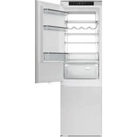
REF24BMBIPNV - Fridge BERTAZZONI - Free user manual and instructions
Find the device manual for free REF24BMBIPNV BERTAZZONI in PDF.


User questions about REF24BMBIPNV BERTAZZONI
0 question about this device. Answer the ones you know or ask your own.
Ask a new question about this device
Download the instructions for your Fridge in PDF format for free! Find your manual REF24BMBIPNV - BERTAZZONI and take your electronic device back in hand. On this page are published all the documents necessary for the use of your device. REF24BMBIPNV by BERTAZZONI.
USER MANUAL REF24BMBIPNV BERTAZZONI
text_image
BERTAZZO ITALIA| EN | INSTALLATION MANUALUSER AND MAINTENANCE MANUALREF24BMBIPNV | 3 |
| FR | MANUEL D'INSTALLATIONMANUEL D'UTILISATION ET D'ENTRETIENREF24BMBIPNV | 25 |
FROM THE DESK OF OUR PRESIDENT
Dear new owner of a Bertazzoni appliance,
I want to thank you for choosing one of our beautiful products for your home.
My family started manufacturing kitchen appliances in Italy in 1882, building a reputation for quality of engineering and passion for good food.
Today, our products stand out because of their unique blend of authentic Italian design and superior appliance technology. It is our mission to make products that function perfectly and bring joy to their owners.
By making beautiful products we respond to our customers' flair for good design. By making them versatile and easy-to-use, cooking with Bertazzoni becomes a real pleasure.
This manual will help you learn to use and care for your Bertazzoni appliance in the safest and most effective way, so that it can give you the highest satisfaction for years to come.
Enjoy!
Paolo Bertazzoni
President
text_image
Pedro SectorzomUSER MANUAL VALIDITY
The following manual is valid only for REF24BMBIPNV product code.
GENERAL INFORMATION 7
READING THE MANUAL 7
INTRODUCTION AND SAFETY 7
SAFETY INFORMATION 8
DISPOSAL OF OLD APPLIANCE 8
ENERGY SAVING 9
BEFORE FIRST USE 9
USE 10
USING THE FRIDGE 10
WATER CONNECTION INSTRUCTIONS 14
CARE AND MAINTENANCE 15
LED LIGHT REPLACEMENT INSTRUCTIONS 15
CARE AND CLEANING 15
DEFROSTING 15
TROUBLESHOOTING 16
INSTALLATION INSTRUCTIONS 17
PREPARING FOR INSTALLATION 17
VENTILATION 17
INSTALLATION INSTRUCTIONS (SLIDING HINGE) 20
MOUNTING THE CABINET DOOR(S) 21
REVERSING THE APPLIANCE DOORS 22
ENSURING THE DOOR SEALS CORRECTLY 23
CUSTOMER CARE 24
Thank you for purchasing this product.
INTRODUCTION AND SAFETY
In order to get the most out of your refrigerator, please read this instruction manual carefully before use. Keep all documentation for use at a later date or for future owners.
Read the instructions provided in this manual carefully before installing and/or using the appliance.
This product is intended solely for residential use or similar. This will help you to get to know your new device. applications, such as:
Keep this document to hand so that you consult it at any gmoment, and hand it on to any subsequent owners.
The staff kitchen areas of shops, offices and other working environments; on farms, by guests at hotels, motels, bed and breakfasts (B&Bs) and other residential-type environments.
It may be used for catering services and similar applications, provided it is not used to store products for retail sale.
This appliance must be used only for purposes of food storage; any other use is considered hazardous and the manufacturer will not be held liable in the event of such use. Also, it is recommended that you take note of the warranty conditions.
READING THE MANUAL
These instructions are suitable for different types of appliances, so they may contain descriptions of functions which your appliance may not contain or support.
The images and illustrations in this document refer to various models and may differ slightly from the product purchased.
The manufacturer does not accept any responsibility for personal injury or damage to property arising from incorrect installation or misuse of the appliance.
The manufacturer reserves the right to modify the various models as required to comply with the technical regulations in force.
In the event of complaints, please contact the customer service.
Read the safety messages provided in the introduction to this manual and give due consideration to the safety notes such as: "Attention", "Warning" and "Danger" which appear in the text.

DANGER
This symbol indicates a situation that is a danger to you and others. Read it carefully and make sure that you have perfectly understood the causes of potential dangerous or fatal accidents.

WARNING
This symbol indicates safety information. Read it carefully and make sure that you have perfectly understood the causes of potential dangerous accidents.

CAUTION
This symbol indicates a procedure which could put the appliance's structure or components at risk. Take particular care over these procedures.

NOTE
This symbol indicates useful advice and draws your attention to correct procedures and practices. Complying with the instructions marked with this symbol will avoid problems for you.
The symbol highlights methods or procedures for correct use of the appliance.
SAFETY INFORMATION
WARNING

Risk of fire / Flammable materials
This appliance is not intended for use by persons (including children) with reduced physical, sensory or mental capabilities or lack of experience and knowledge unless they are supervised or have been given instruction concerning the use of the appliance by a person responsible for their safety.
Children should be supervised to ensure that they do not play with the appliance.
If the power cord is damaged, it must be replaced by the manufacturer, its service agent or a similarly qualified person in order to ensure against hazards.

WARNING
Keep ventilation openings in the enclosure or built-in structure where the appliance is housed free of obstructions.

WARNING
Do not use mechanical devices or other means to accelerate the defrosting process unless they are recommended by the manufacturer.

WARNING
Do not damage the refrigerant circuit.

WARNING
Do not use electrical appliances inside the unit's food storage compartments unless these are of a type recommended by the manufacturer.

WARNING
When positioning the appliance, make sure that the power cord does not become trapped or damaged.

WARNING
Do not place multi-outlet power strips or portable power supplies at the rear of the appliance.
Do not store explosive substances, such as aerosol cans with a flammable propellant, inside this appliance.
This appliance is intended to be used in residential and other similar applications, such as:
- staff kitchen areas in shops, offices and other working environments;
- in farm houses and by guests at hotels, motels and other residential type environments;
• bed and breakfast type environments;
• catering and similar non-retail applications.
Please comply with local regulations when disposing of the appliance, due to its flammable refrigerant and insulation-blowing gas.
If the LED lamp is damaged, it must be replaced by the manufacturer, its service agent or a similarly qualified person in order to ensure against hazards.

WARNING
To prevent hazards associated with appliance instability, the appliance must be anchored according to the instructions.
DISPOSAL OF OLD APPLIANCE
Properly dispose of your appliance packaging. Ensure that refrigeration equipment is disposed of in an environmentally friendly way, including both your old and new appliances at the end of their service life. Follow local regulations for the disposal of appliances with flammable refrigerants and blowing gas.

WARNING
Before disposal, make old, worn appliances unusable by removing the plug, cutting the power cable, and destroying any snap fastenings or bolts. This prevents children from locking themselves inside the appliance during play (risk of suffocation) or causing other dangers.

WARNING
Do not dispose of the appliance with normal household waste. Avoid damaging the coolant circuit, especially the heat exchanger at the back or bottom of the unit.
The symbol on the product or packaging indicates that this product should not be treated as normal household waste. Instead, take it to a recycling collection point for electrical and electronic goods. Correct disposal protects the environment and public health. For more information on recycling, contact your local authorities or waste collection services.
ENERGY SAVING
For optimal energy saving, we recommend the following:
• Install the appliance away from heat sources, out of direct sunlight and in a well-ventilated room.
- Avoid putting hot food into the refrigerator, which would raise the internal temperature, thus causing the compressor to run continuously.
- Do not overfill the compartments, as this prevents air from circulating properly.
- If ice should form, defrost the appliance in order to facilitate the transfer of cold.
- In the event of an electrical power failure, it is advisable to keep the refrigerator door closed.
- Open the appliance doors as infrequently and for the briefest amounts of time possible.
- Do not adjust the settings to extremely cold temperatures.
- Remove any dust that accumulates on the back of the appliance
BEFORE FIRST USE
You must allow the fridge to settle for at least four hours prior to switching the power on.
It is recommended that you clean the interior of the appliance prior to first use using a solution of bicarbonate of soda and warm water, then thoroughly dry the interior. The fridge may have an odour to it at first use. This will disappear as the appliance cools.

NOTE
The appliance will start operating at 41 °F for the fridge and 0 °F for the freezer and work continuously until it comes down to the correct temperatures. If the appliance is switched off, you should allow five minutes before switching it on again in order to prevent unnecessary damage to the compressor. Never store inflammable or explosive items, strong corrosive acids or alkalis in the appliance. This fridge cools your food by making the inside back of the cavity cold. It is normal for frost to build up on this surface; it then dissipates and drains through a small drain at the bottom, where it evaporates harmlessly. The presence of frost at the back does not mean that the fridge is malfunctioning.
USING THE FRIDGE
- Never put liquids into the refrigerator uncovered
- Never put hot foods into the refrigerator. Warm food should be allowed to cool to room temperature before being put into the refrigerator.
- Nothing should rest against the rear wall of the refrigerator, as this will cause the formation of frost, which will be difficult to remove, and possible condensation problems.
- Make sure food is clean and that any excess water is wiped off before putting it into the fridge.
- Wrap or cover food before putting it into the fridge. This will help impede the loss of moisture, keep food fresh and prevent unpleasant odours.
- Sort foods prior to storing. Any foods to be used soon should be stored at the front of the shelves. This will to prevent deterioration, which could occur when the door is kept open for long periods of time.
- Do not overfill the fridge. There should be sufficient space between foods to allow cool air to circulate.
- Thawing frozen foods in the fridge compartment will help to keep the temperature low and save energy.
- Never store raw meats on shelves above cooked meats or produce. This will help to prevent juices from raw meat from contaminating other foodstuffs.
USING THE FREEZER
- The freezer compartments are designed to store frozen food only.
- Never put hot or warm foods into the freezer; allow them to cool fully before putting them into the freezer.
- When storing frozen food, follow the instructions on the food packaging. If no information is provided, foods should not be stored for longer than three months after the purchase date.
- Store food in small packages (ideally less than 2.2 lbs). This reduces freezing time and improves the quality of the food after thawing.
- Wrap food before putting it into the freezer. To stop the wrapping from sticking together, ensure it is dry.
- Label food before freezing, with information including help type of food and dates of storage and expiration.
- Once food is thawed, it must not be refrozen. In order to prevent wastage, only defrost as much food as is required.
- Bottled or canned drinks should not be stored in the freezer compartments, as they could explode.
- The maximum amount of fresh food that can be frozen within a 24-hour period is 5.7 lbs.
- Do not attempt to freeze more than the maximum amount.
FRESCO ZONE DRAWER
- The temperature inside the Fresco drawer can be regulated within a range of between +37 °F and 27 °F. This is the ideal drawer for storing meat and fish.
STORAGE
text_image
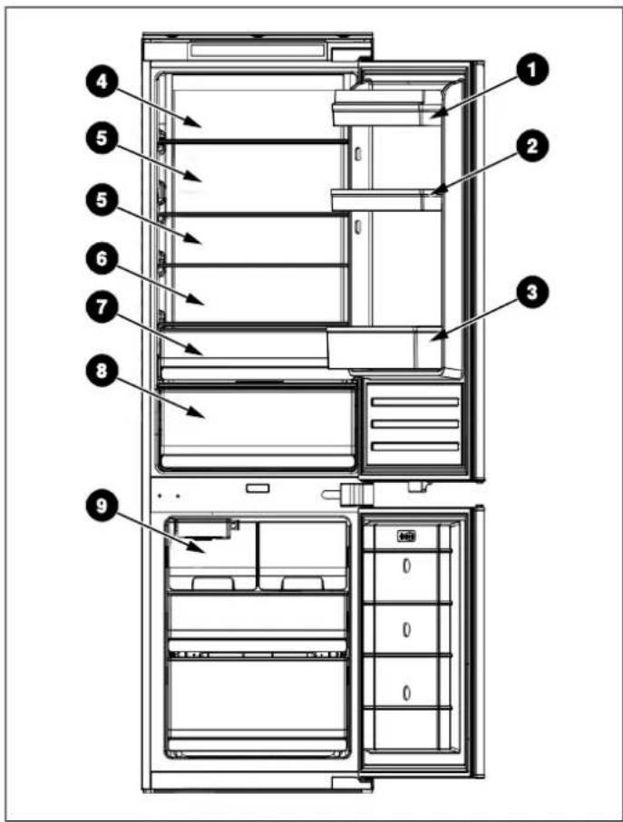
Technical diagram of a refrigerator with numbered parts for identification and assembly reference.The fridge section is for short-term food storage. Although low temperatures can be maintained, it is not recommended to store food for extended periods.
The temperature can vary between the different sections as the cold air circulates within the fridge. For this reason, foods should be stored in different sections according to type.
The fridge shelves can be moved within the refrigerator compartment depending on storage requirements. To move a shelf, lift up the rear section and then pull it outwards.
To replace, slide the shelf back into the slot and then lower the rear section.
The most energy-saving configuration requires the drawers, door bins and shelves to be installed in the appliance; please see the pictures above.
Fig. 1
1 Butter, cheeses, etc.
2 Food in jars and bottles
3 Beverages, e.g. milk
4 Cooked food
5 Yoghurt, preserves, etc.
6 75 cl bottles, ready-made meals, etc.
7 Fruit and vegetables
8 Fresh meat and fish / Fruit and vegetables
9 Ice cubes storage
CONTROL PANEL

natural_image
Row of eight icons including shopping cart, umbrella, water drop, battery, fuel pump, sprout, grocery store, and power button on black background (no text or symbols)Fig. 2
1) When the appliance is switched on for the first time, it will be operating at the following settings: 41°F for the fridge, 32°F for the Fresco and 0°F for the freezer. If you wish adjust the temperature or functions manually, use the appropriate button to perform the desired operation. The temperature range for the Fresco is from 27°F to 37°F.
2) Fridge temperature adjustment: Press the button on the left-hand side of the control panel to adjust the temperature within a range of between 36°F and 46°F.
3) Freezer temperature adjustment: Press the button on the right-hand side of the control panel to adjust the temperature within a range of between 5°F and -13°F.
4) Fresco drawer temperature adjustment: The button controls temperature. By pressing on this button, you can adjust the temperature within a range of between 27°F and 37°F. This function can be turned on/off by pressing and holding the button for three seconds (OFF is displayed).
5) Super Cool: Press the button; the button lights up and the fast cooling function is turned on. The fridge automatically begins running at a temperature setting of 36^ F and continues for 24 hours, after which it returns its normal setting and the symbol is no longer lit.
6) Holiday Mode: Press the button; the button lights up, the holiday function is turned on and the whole appliance automatically begins running at the following settings: fridge at 63 °F and freezer at 0 °F.
Eco Mode: Press the button on the control panel; the Eco function is turned on and the button lights up. The ridge compartment runs at a setting of 41°F and the freezer compartment runs at a setting of 0°F. The Fresco works at a setting of 37°F.
8) Super Freeze: Press the button; the button lights up and the freezer begins to run the fast freezing function, with a temperature setting of -13^ F. After 24 hours, the fast freezing function quits automatically.
9) Press and hold the power button for 3 seconds to switch off your appliance. The button lights up and the power is shut off. The interior lamps switch off and the compressor stops operating. Press and hold the button for 3 seconds to switch on your appliance. The symbol lights up and power is restored.
10) No Frost models are equipped with a manual defrosting function. Press and hold buttons + for 5 seconds to switch on the manual defrosting function to clean the freezer evaporator. The freezer temperature symbol remains steadily lit. Press and hold buttons + for 3 seconds to switch off the manual defrosting function. To The freezer temperature symbol goes dark.
11) Fault Display: This appliance has a "Fault Display & Alarm" function. Once the sensors detect a fault, alerts are shown on the temperature display; the appliance still cools, but a professional service engineer should be called in to check it.
• F2 – Fresco sensor
• F3 – Fridge compartment sensor
• F4 – Freezer compartment sensor
• F5 – Defrosting sensor
• 2E – Freezer fan/motor fault
- CE– Communication fault between main board and display panel
The above Faults are only shown on the display; there is no audible alarm signal.
Maximum freezer temperature exceeded alarm: If, after the freezer reaches the set temperature, the temperature rises to above 30^ F, the alarm will sound, accompanied by simultaneous flashing of the freezer temperature display. Press any button to cancel the audible alarm. The flashing will continue until the temperature falls below 30^ F.

NOTE
The main board is located in the compressor compartment.
POSITION CONDITIONS
| 41°F / 0°F | Summer or ambient temperature |
| between 77°F - 95°F | |
| 41°F / 0°F | Spring, autumn or ambient temperature |
| between 59°F - 77°F | |
| 41°F / 0°F | Winter or ambient temperature |
| between 41°F - 59°F | |
| Super Freezing function Super Freeze | |
| Super Cooling function Super Cool | |
ICE MAKER INSTRUCTIONS
Key Operation Instructions:
1) Short press the button to switch the ice machine on or off.
2) When the machine is on, press and hold the button for 10 seconds to manually de-ice.
Lamp Status Description:
1) Switch On State: the light will fade on and then fade off.
2) Switch Off State: the light remains off.
3) Ice Full State: the light stays on continuously.
4) Drawer Removal: the light flashes slowly once every 0.5 seconds (1Hz)
Fault Status:
1) Ice Jam: the light flashes quickly once every 200 ms.
text_image
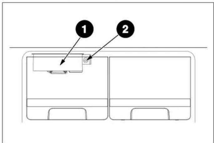
Diagram showing two labeled components (1 and 2) pointing to a device inside a rectangular frame, likely illustrating a system or layout concept.Fig. 3
1 Ice Maker
2 Ice Maker Switch
WATER CONNECTION INSTRUCTIONS
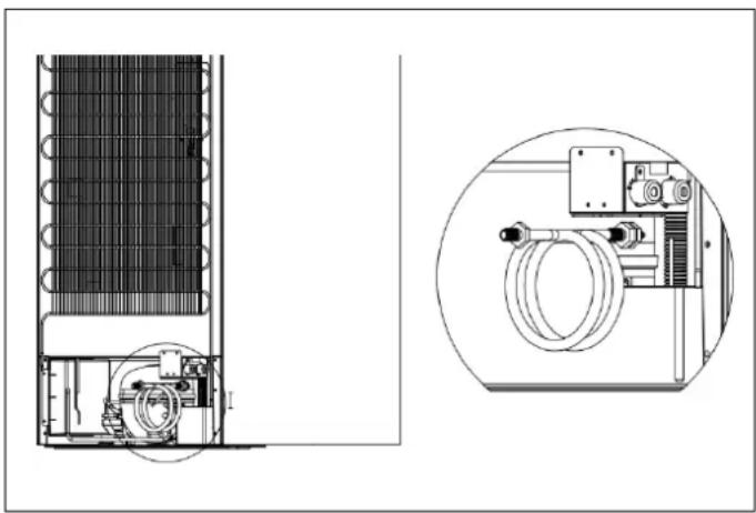
The refrigerator is equipped with a 59" long water hose (1/4" diameter) that includes a female 1/4" compression fitting nut, provided in the accessory bag inside the refrigerator packaging.
Before installation, the refrigerator's water system must be connected to the house's main water supply. To do this, connect the water hose to the rear of the refrigerator and then to your home's water supply.
The refrigerator does not come with a water filter. However, a third-party water filter can be installed if desired. The water supply line must be located either inside the cabinet where the appliance is installed or in an adjacent cabinet, with an opening at the rear of one of these cabinets.
The refrigerator's water system must be connected to the house's main water supply.
The pressure of the water system must be between 25-80 psi (1.7-5.5 bar). If the water pressure exceeds 80 psi (5.5 bar) but remains below 120 psi (8 bar), install a pressure limiting device or water impact protector to the inlet valve.

NOTE
Once the connection is complete, open the water valve and make sure that there is no leakage. Otherwise, water may damage the cabinetry.
natural_image
Technical line drawing of a refrigerant system with internal components and a magnified inset showing internal wiring (no text or labels)Fig. 4

WARNING
Do not install or operate the appliance if the water pressure exceeds 120 psi (8 bar). Objects that might pierce the water hose or cause them to twist must not be present where the water line is installed

WARNING
The hose that runs from the water supply must be one piece. Do not use extension hoses.

WARNING
Make sure that the power is cut off when establishing the appliance's water connection.

WARNING
The water valve must be closed when connecting the water hose.

WARNING
It is strongly recommended to keep the water valve accessible after product installation.

WARNING
This appliance is suitable for use with a cold potable water supply only.
LED LIGHT REPLACEMENT INSTRUCTIONS

NOTE
The LED light is intended to be non-replaceable by the user; it needs to be replaced by a service professional.
Lighting parameters: 12V / 10W
1) Unplug the power plug.
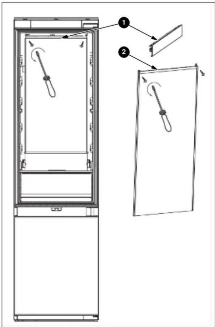
2) Remove the aluminium alloy trim strip on the top of the LED surface light source, then remove the left and right mounting screws.
Steps 1 and 2 are shown below.
3) Install the new LED light board.
4) Finally, replace the aluminium alloy trim strip.
text_image
Technical diagram showing two views of a refrigerator with labeled parts and directional arrows indicating motion or movement.Fig. 5
CARE AND CLEANING
Always disconnect the appliance from the mains power before performing any cleaning or maintenance.
The fridge and freezer sections should be cleaned using a solution of bicarbonate of soda and lukewarm water. Do not use abrasive products or detergents. After washing, rinse and dry thoroughly.
Clean the shelves and door bins separately by hand with a mild solution of washing-up liquid and water. Do not put them in the dishwasher.
If the appliance is not going to be used for an extended period of time, unplug and clean the appliance. The doors should be left slightly ajar to prevent the formation of mildew and unpleasant odours.
DEFROSTING
The product has a No Frost system, which is designed to prevent heavy build-up of ice. Under normal conditions of use, there should be no need to regularly defrost the freezer system.

NOTE
If you are regularly finding a heavy build-up of ice or puddles of water in the freezer section, then it is likely that the door is not sealing properly. This could be due to a defective door seal or an incorrectly fitted or overly heavy cabinet door panel. For more information, see the troubleshooting section about ice.
TROUBLESHOOTING
If you have any problems with your appliance, you should check this troubleshooting section prior to calling Customer Care.
If the appliance is not working, check that:
• The appliance is receiving electrical power.
- The fuses in the home are intact and the fuse in the plug has not blown.
• The fridge has not been turned off.
- The electrical outlet is functioning properly. To check this, plug another electrical appliance into it to see if the outlet is faulty.
If the appliance is working, but not very well, check that:
• The appliance is not overloaded.
- The thermostat is set to an appropriate temperature.
• The doors are closing properly.
- The cooling system on the back of the appliance is clean and free of dust and is not touching the rear wall.
- There is enough ventilation around the side and rear walls.
If the appliance is noisy, check that:
• The appliance is level and stable.
- The side and rear walls are clear and there is nothing resting against the appliance.

NOTE
The coolant gas in the refrigerator may make a slight bubbling or gurgling noise, even when the compressor is not running.
If the appliance is beeping, check that:
- The doors are closed. An alarm will sound after a door has been open for 60 seconds.
If ice has formed on the back wall of the fridge:
- It is normal for some ice droplets to form on the back wall of the fridge. This does not constitute a fault with the appliance.
- Ensure that no items inside the fridge are in contact with the back wall.
- Check that there is some resistance when opening the appliance door. If it opens at the slightest touch, it may mean that the door seal needs to be replaced.
- Check the door seal for any kinks, debris or damage. If you notice any, and are unable to resolve the issue yourself, contact Customer Care so that the seal can be replaced.
- This can be due to the cabinet door(s) not being properly fitted. If you are at all unsure, ask your installer to check the cabinet doors.
If excessive ice has formed in the freezer:
- Check that there is some resistance when opening the appliance door. If it opens at the slightest touch, it may mean that the door seal needs to be replaced.
- Check the door seal for any kinks, debris or damage. If you notice any, and are unable to resolve the issue yourself, contact Customer Care so that the seal can be replaced.
- This can be due to the cabinet door(s) not being properly fitted. If you are at all unsure, ask your installer to check the cabinet doors.
If one or more of the LED units inside the appliance is not working:
- Contact Customer Care to arrange a service visit.
PREPARING FOR INSTALLATION
This appliance must not be installed close to heat sources, e. g. heating elements or cookers, or in a damp location.
Seek the help of one or two other individuals when installing this appliance. This appliance may have sharp edges. Wear PPE appropriate to the task and the environment.
- Use the height-adjustable feet at the front of the appliance to ensure that the appliance is level.
- The cooling system on the back of the appliance must not touch the rear wall. The larger the gap, the better.
- The appliance must be installed with adequate ventilation. Ensure that there is clearance above the appliance to allow air to escape and that there is space between the rear of the appliance and the wall.
VENTILATION
The main consideration when installing any refrigeration unit into a fitted kitchen is ventilation. The heat removed from the cooling compartment needs to be dissipated into the air around the appliance. Incorrect ventilation can lead to premature compressor failure, excessive power consumption and total system failure, and it may invalidate the warranty provided with the appliance.

natural_image
Technical line drawing of two rectangular metal cabinets with a rotation arrow indicating assembly (no text or symbols)Fig. 6
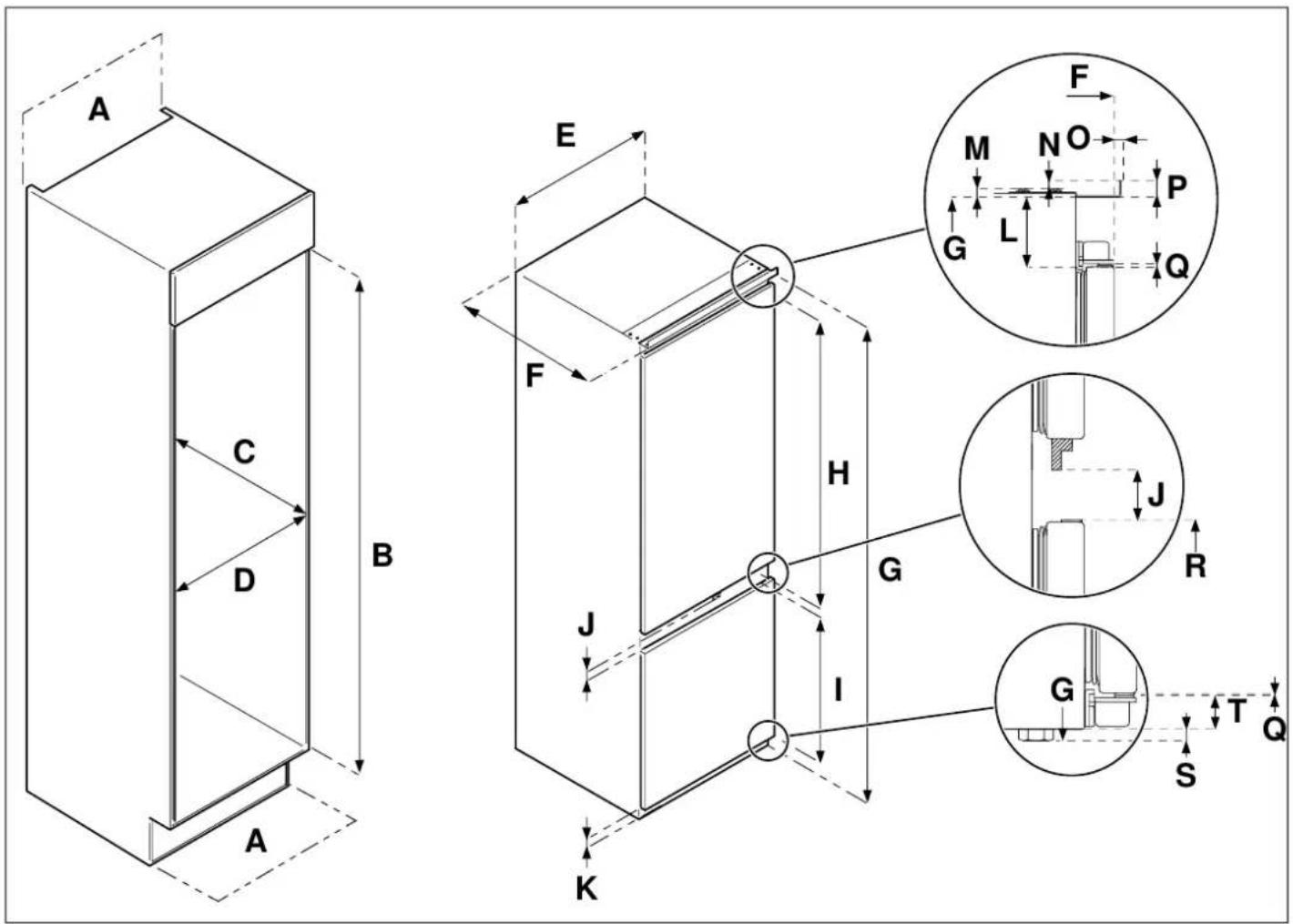
For appliances intended to be installed inside a tall housing cabinet, the requirements in the Fig. 7 must be met.
text_image
A C D B A E F H J G I K F M N O P G L Q J R G S T QFig. 7
| A | B | C | D E F | G | H | I | |||
| min31 sq. in. | 70" - 70 1/8" | min22 1/16" | min22 1/16" | 21 1/4" | 21 5/8" | 69 15/16" | 39 9/16" | 25 3/16" | |
| J K L M N | O | P | Q | R | S | T | |||
| 1 5/8" | 1 5/16" | 2" | 1/4" | 3/8" | 1/4" | 9/16" | 1/16" | 26 1/2" | 5/16" |
text_image
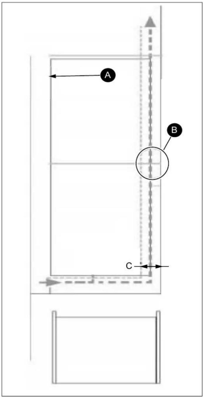
A B CFig. 8
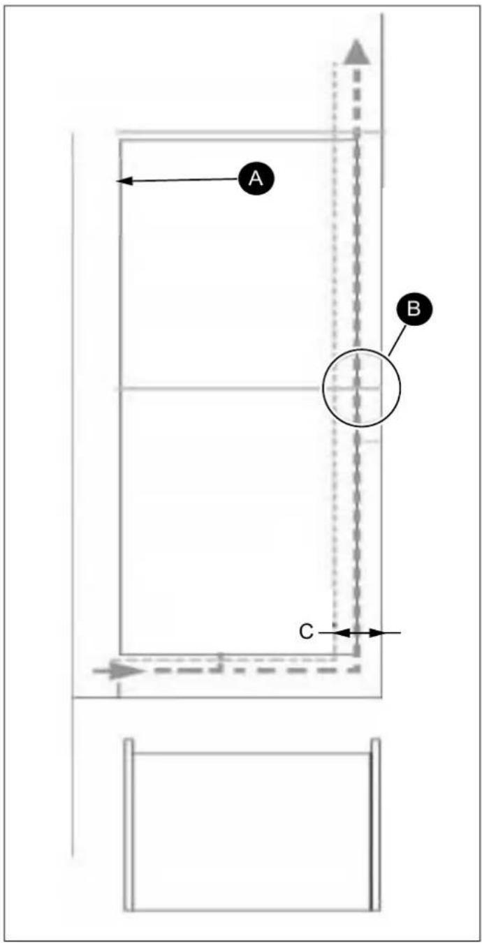
• A Refrigerator outline
B Recommended size of vent opening: 19 11/16" x 1 3/16"
• C min. 1 3/16"
There should be an air intake somewhere inside the cabinet to allow air into flow freely in. In this example, a base vent is shown underneath the refrigerator.
A cut-out should be made in the base beneath the fridge/freezer and this finished neatly around the air vent grille.
Alternatively, a thin section of the base can be removed to allow air into the unit (the recommended size is 23 5/8" x 3/8").
The top of the cabinet needs to be vented into the room.
If the cabinet does not allow air to flow freely into the room, then a base vent or other means of ventilation needs to be provided to ensure a natural flow of air.
There should be space at the rear of the cabinet to allow cool air to be drawn over the condenser.
Recommended: 19 11/16" x 1 3/8"
The clearance at the rear of the appliance is clearly shown. In order for the appliance to operate properly, it is important that the top of the housing cabinet not be blocked off. A channel depth of 1 9/16" - 2" is normal for most units.
A ventilation hole is required in the base of the cabinet; this allows for air to be drawn over the compressor and for heat exchange.
As a rule, the more air can get in and out, the better and more efficiently the product operates.
INSTALLATION INSTRUCTIONS (SLIDING HINGE)
With the help of one or two other individuals, move the appliance into the cabinet. There are two metal plates at the base of the appliance. Fit the supplied white spacers to these plates; when finished, snap off the inverted "T" section.
1) Insert the appliance into the cabinet, placing it on the far side with respect to the hinges, making sure to leave a 1/8" - 3/16" gap.

natural_image
Line drawing of a refrigerator with a vertical arrow labeled 'A' pointing to the side panel (no text or symbols on the refrigerator itself)Fig. 9
A 1/8" - 3/16"
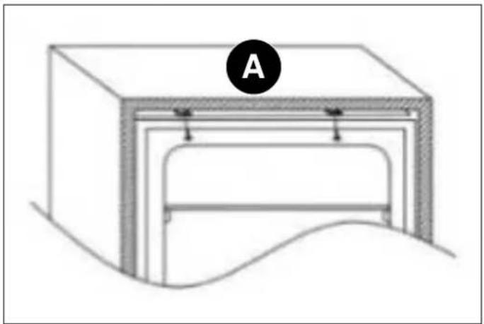
2) After checking the alignment of the appliance door and the cabinet door, mount the plastic covers from the accessories bag.
natural_image
Diagram of a mechanical or architectural component with labeled section A, showing layered structure and curved base (no text or symbols beyond label)Fig. 10
A top
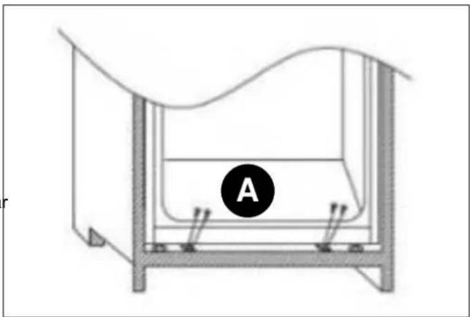
3) Tighten the screws for the appliance's lower part.
natural_image
Diagram of a laboratory apparatus with labeled component A, showing internal structure and supports (no text or symbols beyond label)Fig. 11
A bottom
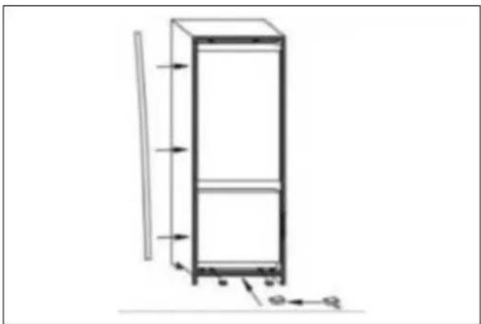
4) Fit the seal onto the appliance, cutting off any excess as necessary. Mount the plastic covers on the bottom parts.
natural_image
Technical line drawing of a vertical cabinet with directional arrows indicating movement (no text or symbols)Fig. 12
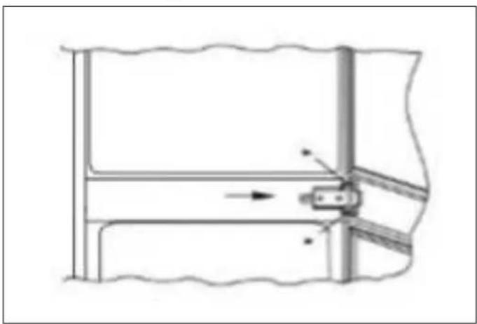
5) Use a crosshead screwdriver to loosen the connecting pin underneath the right middle hinge and adjust it to screw onto the right cabinet wall.
natural_image
Pure mechanical diagram showing a lever mechanism with no text or symbolsFig. 13
MOUNTING THE CABINET DOOR(S)
1) Ensure that there is a gap of 1/8" to 3/16" between the non-hinged side of the fridge and the cabinet wall.
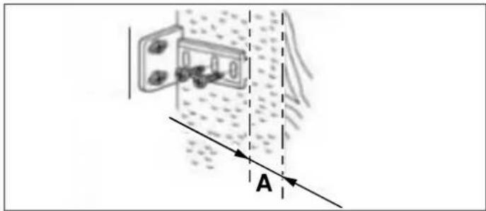
2) Locate the slider in the bracket and mount the slider on the cabinet door, 13/16" to 7/8" from the long edge of t cabinet door, as shown in the following image, ensuring that the slider is positioned centrally and horizontally within the bracket. Tighten securely by hand.
text_image
Diagram illustrating light refraction through a device with labeled point A and directional arrowsFig. 14
A 13/16"
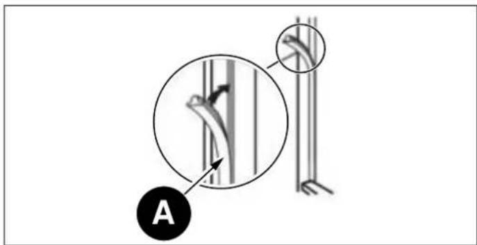
3) Fill the gap on the non-hinged side with the gasket/sealing strip provided.
text_image
AFig. 15
A Seal
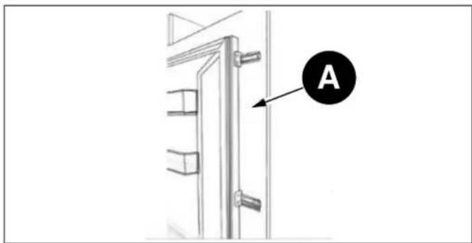
4) The finished look for the door sliders should be similar to those shown in the following image, which shows 2 sliders in place.
text_image
AFig. 16
A Cabinet door
Ensure the appliance doors open, close and seal properly.
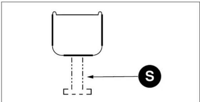
Once complete, and if you are happy with the fit of the appliance in the cabinet, bend and snap off the parts of the white spacers marked "S", as shown by the dotted outline.
text_image
Diagram showing a wine glass with a labeled arrow pointing to the letter 'S' and a dashed line indicating a vertical path.Fig. 17
Leave the remaining portions of the spacer covers in place over the metal plates.

NOTE
After completing the installation, check that the appliance is secure within the cabinet and that the door (s) close and open properly. If there is no resistance from the door seals when opening the door(s), then it is probable that the appliance and/or cabinet door(s) are not fitted properly.
REVERSING THE APPLIANCE DOORS
We recommend you seek the help of another individual to support the doors while you perform this operation.
1) Remove the upper right hinge cover and hinge using a screwdriver.
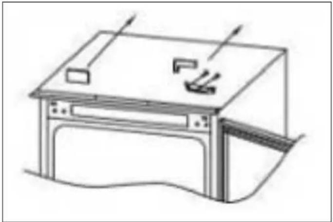
natural_image
Line drawing of a vintage office setup with monitor, keyboard, and lamp (no text or symbols)Fig. 18
2) Remove the upper door.
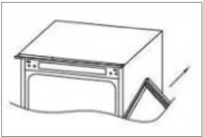
natural_image
Simple line drawing of a cabinet or enclosure with an arrow indicating motion (no text or symbols)Fig. 19
3) Remove the middle hinge and its connecting pin underneath.
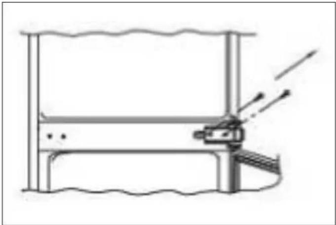
natural_image
Pure technical diagram of a mechanical assembly without any text, numbers, or symbolsFig. 20
4) Remove the bottom door.
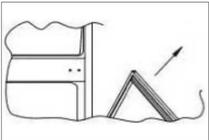
natural_image
Simple line drawing of a roof structure with a triangular roof and an arrow indicating direction (no text or symbols)Fig. 21
5) Remove the bottom right hinge and left plastic plugs, and remount them on the opposite sides.
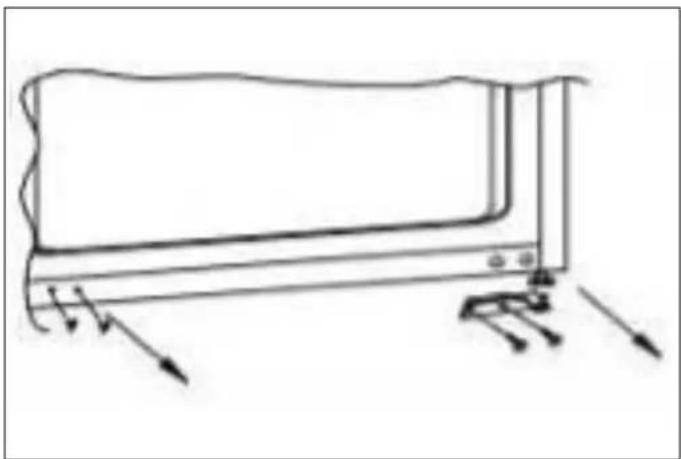
natural_image
Line drawing of a device with arrows indicating motion or force, no text or symbols presentFig. 22
6) Mount the right upper hinge on the bottom left corner and install the cover.
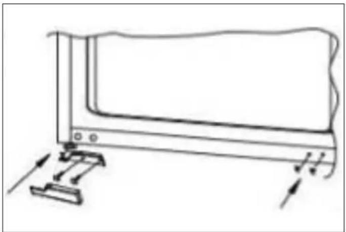
natural_image
Line drawing of a computer monitor with a base and cable, showing no text or symbolsFig. 23
7) Remount the doors and hinges, working from bottom to top (from 1-4).
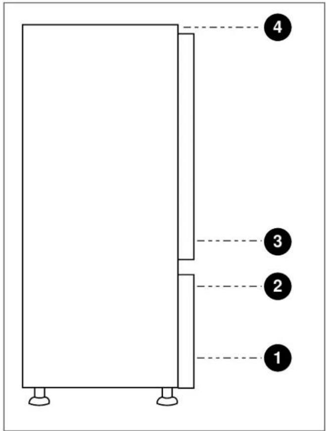
text_image
4 3 2 1Fig. 24
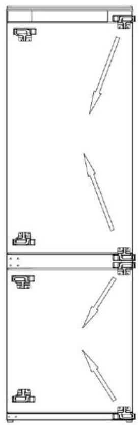
natural_image
Pure technical diagram of a mechanical or electrical component with directional arrows, no text or symbols presentFig. 25
ENSURING THE DOOR SEALS CORRECTLY
It is normal for the seal to be compressed after the door has been reversed. With the door closed, use a hair dryer to expand the seal and fill the gap between the door and the body of the appliance. Take care not to hold the hair dryer too close to the appliance, which could damage the seal.
A distance of approximately 3 15/16" should be suitable. When completed, allow the seal and door to cool before touching them. Once done, the seal should remain in position.
For any warranty information and service request, contact us:
text_image
CUSTOMER CAREIn USA: https://us.bertazzoni.com/more/support
In CANADA: https://ca.bertazzoni.com/more/support
DU BUREAU DE NOTRE PRÉSIDENT
text_image
Technical diagram of a refrigerator with numbered parts for identification and assembly reference.natural_image
Row of eight icons including recycling, shopping cart, tree, water drop, blank rectangle, fuel pump, sprout, and power button (no text or symbols)Fig. 2
text_image
Diagram showing two labeled components (1 and 2) pointing to a device inside a container or enclosure, with arrows indicating direction.Fig. 3
natural_image
Technical line drawing of a refrigerant system with internal components and a magnified inset showing internal wiring (no text or labels)Fig. 4

MISE EN GARDE
text_image
Technical diagram showing two views of a refrigerator with labeled parts and directional arrows indicating motion or movement.Fig. 5
natural_image
Technical line drawing of two rectangular metal cabinets with a rotation arrow indicating assembly (no text or symbols)Fig. 6
text_image
A C D B A E F H J I K G L M N O P Q F J R G S T QFig. 7
| A | B | C | D E F | G | H | I | |||
| Min.31 pouces carrés | 70" - 70 1/8" | min22 1/16" | min22 1/16" | 21 1/4" | 21 5/8" | 69 15/16" | 39 9/16" | 25 3/16" | |
| J K L M N | O | P | Q | R | S | T | |||
| 1 5/8" | 1 5/16" | 2" | 1/4" | 3/8" | 1/4" | 9/16" | 1/16" | 26 1/2" | 5/16" |
text_image
A B CFig. 8
natural_image
Line drawing of a refrigerator with a vertical measurement line labeled 'A' (no text or symbols on the refrigerator itself)Fig. 9
A 1/8" - 3/16"
natural_image
Diagram of a mechanical or architectural component with labeled section A, showing internal layers and a curved base (no text or symbols beyond label)Fig. 10
natural_image
Diagram of a laboratory apparatus with a labeled component 'A' (no text or symbols beyond label)Fig. 11
natural_image
Technical line drawing of a vertical cabinet or enclosure with directional arrows indicating movement (no text or symbols)Fig. 12
natural_image
Pure mechanical diagram showing a lever mechanism with no text or symbolsFig. 13
MONTAGE DE LA OU DES PORTES DE L'ARMOIRE
text_image
Diagram illustrating light refraction through a device with labeled point A and directional arrowsFig. 14
A 13/16"
text_image
Diagram showing a wine glass with a labeled arrow pointing to the letter 'S' and a dashed line indicating a vertical path.Fig. 17
natural_image
Line drawing of a mechanical device with no visible text or symbolsFig. 18
natural_image
Simple line drawing of a cabinet or enclosure with an arrow indicating motion (no text or symbols)Fig. 19
natural_image
Technical line drawing of a mechanical assembly with no visible text or symbolsFig. 20
natural_image
Simple line drawing of a building with a triangular structure and an arrow pointing upward (no text or symbols)Fig. 21
natural_image
Line drawing of a device with arrows indicating motion or force, no text or symbols presentFig. 22
natural_image
Line drawing of a computer monitor with a stand and directional arrows indicating motion (no text or symbols)Fig. 23
natural_image
Technical line drawing of a vertical rectangular structure with internal arrows indicating directional flow (no text or symbols)Fig. 25
ASSURER LA BONNE ÉTANCHÉITÉ DE LA PORTE
text_image
CUSTOMER CAREAu Canada: https://ca.bertazzoni.com/more/support
www.bertazzoni.com
Via Palazzina. 8.
42016 Guastalla RE