
31‑140 - Sander DELTA - Free user manual and instructions
Find the device manual for free 31‑140 DELTA in PDF.

| Product Type | Disc Sander |
| Brand | Delta |
| Model | 31‑140 |
| Disc Diameter | 30.5 cm (12 in) |
| Speed | 1725 RPM |
| Motor | 1/2 HP, 120 V, 1 Ph, 60 Hz |
| Power Supply | 115 V, 60 Hz (wired for 115 V) |
| Rated Current | 6 A (12 A max with extension cord) |
| Table Tilt Range | +45° to -45° |
| Table Dimensions | 43.81 cm × 15.87 cm |
| Net Weight | 32.65 kg |
| Height | 38.10 cm |
| Width | 43.81 cm |
| Dust Port | 5.71 cm (2.25 in) |
| Miter Gauge Slot | 0.95 cm × 1.90 cm |
| Brake | Manual Disc Brake |
| Safety Feature | Removable safety key, ON/OFF switch |
| Warranty | 5-Year Limited |
| Maintenance | Sealed, lubricated-for-life bearings, no additional lubrication needed |
| Included Accessories | Miter gauge, dust hose, Allen wrenches |
Frequently Asked Questions - 31‑140 DELTA
User questions about 31‑140 DELTA
0 question about this device. Answer the ones you know or ask your own.
Ask a new question about this device
Download the instructions for your Sander in PDF format for free! Find your manual 31‑140 - DELTA and take your electronic device back in hand. On this page are published all the documents necessary for the use of your device. 31‑140 by DELTA.
USER MANUAL 31‑140 DELTA
natural_image
Line drawing of a mechanical grinding machine with a circular blade and base plate (no text or symbols)31- 140

TABLE OF CONTENTS
IMPORTANT SAFETY INSTRUCTIONS....2
SAFETY GUIDELINES - DEFINITIONS....3
GENERAL SAFETY RULES ....3
POWER CONNECTIONS 5
MOTOR SPECIFICATIONS....5
GROUNDING INSTRUCTIONS ....5
EXTENSION CORDS 6
FEATURES AND COMPONENTS....6
FUNCTIONAL DESCRIPTION ....7
PRODUCT SPECIFICATIONS....7
UNPACKING 7
ASSEMBLY 8
Install Brake Lever Assembly 8
Secure Tool to Supporting Surface 8
Connect to Dust Hose to Dust Collector System....8
OPERATION 9
Starting and Stopping....9
Removing the Safety Key to Lock the Sander....9
Using the Manual Disc Brake....9
Angle d and End Sanding Using The Miter Gauge....10
Bevel Sanding Using the Table Tilt....10
ADJUSTMENTS....11
Adjust Miter Gauge Slot Alignment 11
Squaring the Table to the Sanding Disc....11
RECOMMENDED MAINTENANCE....12
Lubrication....12
Routine Inspection 12
Replacing Sanding Disc 12
ACCESSORIES....12
WARRANTY 13
REPLACEMENT PARTS....13
SERVICE AND REPAIRS....13
FRANÇAIS....14
ESPAÑOL 27
IMPORTANT SAFETY INSTRUCTIONS
⚠ WARNING: READ AND UNDERSTAND ALL WARNINGS AND OPERATING INSTRUCTIONS BEFORE USING THIS EQUIPMENT. Failure to follow all instructions listed below, may result in electric shock, fire, and/or serious personal injury or property damage.
Woodworking can be dangerous if safe and proper operating procedures are not followed. As with all machinery, there are certain hazards involved with the operation of the product. Using the machine with respect and caution will considerably lessen the possibility of personal injury. However, if normal safety precautions are overlooked or ignored, personal injury to the operator may result. Safety equipment such as

guards, push sticks, hold-downs, featherboards, goggles, dust masks and hearing protection can reduce your potential for injury. But even the best guard won't make up for poor judgment, carelessness or inattention. Always use common sense and exercise caution in the workshop. If a procedure feels dangerous, don't try it. Figure out an alternative procedure that feels safer. REMEMBER: Your personal safety is your responsibility. For additional information please visit our website www.DeltaMachinery.com.
⚠ WARNING: This machine was designed for certain applications only. DELTA® Power Equipment Corporation strongly recommends that this machine not be modified and/or used for any application other than that for which it was designed. If you have any questions relative to a particular application, DO NOT use the machine until you have first contacted DELTA® to determine if it can or should be performed on the product.
If you have any questions relative to its application DO NOT use the product until you have written DELTA* Power Equipment Corporation and we have advised you. Contact us online at www.DeltaMachinery.com or by mail at Technical Service Manager, DELTA* Power Equipment Corporation, 2651 New Cut Road, Spartanburg, SC 29303.
Information regarding the safe and proper operation of this tool is available from the following sources:
• Power Tool Institute, 1300 Sumner Avenue, Cleveland, OH 44115-2851 or online at www.powertoolinstitute.com
• National Safety Council, 1121 Spring Lake Drive, Itasca, IL 60143-3201
• American National Standards Institute, 25 West 43rd Street, 4 floor, New York, NY 10036 www.ansi.org - ANSI01.1 Safety Requirements for Woodworking Machines
• U.S. Department of Labor regulations www.osha.gov
SAFETY GUIDELINES - DEFINITIONS
This manual contains information that is important for you to know and understand. This information relates to protecting YOUR SAFETY and PREVENTING EQUIPMENT PROBLEMS. To help you recognize this information, we use the symbols below. Please read the manual and pay attention to these sections.
DANGER:
Indicates an imminently hazardous situation which, if not avoided, will result in death or serious injury.
WARNING:
Indicates a potentially hazardous situation which, if not avoided, could result in death or serious injury.
CAUTION:
Indicates a potentially hazardous situation which, if not avoided, may result in minor or moderate injury.
CAUTION
Used without the safety alert symbol indicates potentially hazardous situation which, if not avoided, may result in property damage.
GENERAL SAFETY RULES
WARNING:
WARNING FAILURE TO FOLLOW THESE RULES MAY RESULT IN SERIOUS PERSONAL INJURY.
FOR YOUR OWN SAFETY, READ AND UNDERSTAND THE INSTRUCTION MANUAL BEFORE OPERATING THE UNIT. Learn the unit's application and limitations as well as the specific hazards peculiar to it.
- KEEP WORK AREA CLEAN. Cluttered areas and benches invite accidents.
- DON'T USE IN DANGEROUS ENVIRONMENT. Don't use this unit in damp or wet locations, or expose it to rain. Keep work area well-lighted.
- KEEP CHILDREN AND VISITORS AWAY. All children and visitors should be kept a safe distance from work area.
• DISCONNECT UNIT before servicing.
- CHECK DAMAGED PARTS. Before further use of the unit, properly repair or replace any part that is damaged.
WARNING:
FAILURE TO FOLLOW THESE RULES MAY RESULT IN SERIOUS INJURY.
- Read and understand the warnings posted on the machine and in this manual. Failure to comply with all of these warnings may cause serious injury.
- Replace the warning labels if they become obscured or removed.
- This Disc Sander is designed and intended for use by properly trained and experienced personnel only. If you are not familiar with the proper and safe operation of an edge sander, do not use until proper training and knowledge have been obtained.
- Do not use this machine for other than its intended use. If used for other purposes, DELTA® Power Equipment Company, Inc. disclaims any real or implied warranty and holds itself harmless from any injury that may result from that use.
- Always wear approved safety glasses/face shields while using this disc sander.
- Before operating this sander, remove tie, rings, watches and other jewelry, and roll sleeves up past the elbows. Remove all loose clothing and confine long hair. Non-slip footwear or anti-skid floor strips are recommended. Do not wear gloves.
- Wear ear protectors (plugs or muffs) during extended periods of operation.
- Some dust created by power sanding, sawing, grinding, drilling and other construction activities contain chemicals known to cause cancer, birth
defects or other reproductive harm. Some examples of these chemicals are:
- Lead from lead based paint.
- Crystalline silica from bricks, cement and other masonry products.
- Arsenic and chromium from chemically treated lumber.
Your risk of exposure varies, depending on how often you do this type of work. To reduce your exposure to these chemicals, work in a well-ventilated area and work with approved safety equipment, such as face or dust masks that are specifically designed to filter out microscopic particles.
- Do not operate this machine while tired or under the influence of drugs, alcohol or any medication.
- Make certain the switch is in the OFF position before connecting the machine to the power source.
- Make certain the machine is properly grounded.
- Make all machine adjustments or maintenance with the machine unplugged from the power source.
- Form a habit of checking to see that all extra equipment such as adjusting keys, wrenches, scrap, stock, and cleaning rags are removed away from the machine before turning on.
- Keep safety guards in place at all times when the
continued on page 4
machine is in use. If removed for maintenance purposes, use extreme caution and replace the guards immediately when maintenance is complete.
- Make sure the sander is firmly secured before use.
- Check damaged parts. Before further use of the machine, a guard or other part that is damaged should be carefully checked to determine that it will operate properly and perform its intended function. Check for alignment of moving parts, binding of moving parts, breakage of parts, mounting and any other conditions that may affect its operation. A guard or other part that is damaged should be properly repaired or replaced.
- Provide for adequate space surrounding work area and non-glare, overhead lighting.
- Keep the floor around the machine clean and free of scrap material, oil and grease.
- Keep visitors a safe distance from the work area. Keep children away.
- Make your workshop child proof with padlocks, master switches or by removing starter keys.
- Give your work undivided attention. Looking around, carrying on a conversation and "horse-play" are careless acts that can result in serious injury.
- Maintain a balanced stance at all times so that you do not fall or lean against the sanding disc or other moving parts. Do not overreach or use excessive force to perform any machine operation.
- Use the right tool at the correct speed and feed rate. Do not force a tool or attachment to do a job for
which it was not designed. The right tool will do the job better and safer.
- Use recommended accessories; improper accessories may be hazardous.
- Maintain machinery with care. Follow instructions for lubricating and changing accessories.
- Turn off the machine before cleaning. Use a brush or compressed air to remove dust or debris — do not use your hands.
- Do not stand on the machine. Serious injury could occur if the machine tips over.
- Never leave the machine running unattended. Turn the power off and do not leave the machine until it comes to a complete stop.
- At all times hold the stock firmly.
- Do not use this sander for other than it intended use. If used for other purposes, DELTA® Power Equipment Corporation. disclaims any real or implied warranty and holds itself harmless for any injury or damage which may result from that use.
Familiarize yourself with the following safety notices used in this manual:
CAUTION:
This means that if precautions are not heeded, it may result in minor injury and/or possible machine damage.
WARNING:
This means that if precautions are not heeded, it may result in serious injury or possibly even death.
SAVE THESE INSTRUCTIONS.
Refer to them often and use them to instruct others.
POWER CONNECTIONS
A separate electrical circuit should be used for your machines. This circuit should not be less than #12 wire and should be protected with a 20 Amp time lag fuse. If an extension cord is used, use only 3-wire extension cords which have 3-prong grounding type plugs and matching receptacle which will accept the machine's plug. Before connecting the machine to the power line, make sure the switch (s) is in the "OFF" position and be sure that the electric current is of the same characteristics as indicated on the machine. All line connections should make good contact. Running on low voltage will damage the machine.
DANGLE: OSE THE MACHINE TO RAIN OR OPERATE THE MACHINE IN DAMP LOCATIONS.
MOTOR SPECIFICATIONS
Your machine is wired for 115 volts, 60 HZ alternating current. Before connecting the machine to the power source, make sure the switch is in the "OFF" position.
GROUNDING INSTRUCTIONS
▲ DANGER: THIS MACHINE MUST BE GROUNDED WHILE IN USE TO PROTECT THE OPERATOR FROM ELECTRIC SHOCK.
1. All grounded, cord-connected machines:
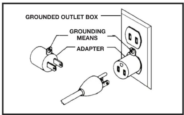
In the event of a malfunction or breakdown, grounding provides a path of least resistance for electric current to reduce the risk of electric shock. This machine is equipped with an electric cord having an equipment-grounding conductor and a grounding plug. The plug must be plugged into a matching outlet that is properly installed and grounded in accordance with all local codes and ordinances.
Do not modify the plug provided - if it will not fit the outlet, have the proper outlet installed by a qualified electrician.
Improper connection of the equipment-grounding conductor can result in risk of electric shock. The conductor with insulation having an outer surface that is green with or without yellow stripes is the equipment-grounding conductor. If repair or replacement of the electric cord or plug is necessary, do not connect the equipment-grounding conductor to a live terminal.
Check with a qualified electrician or service personnel if the grounding instructions are not completely understood, or if in doubt as to whether the machine is properly grounded.
Use only 3-wire extension cords that have 3-prong grounding type plugs and matching 3-conductor receptacles that accept the machine's plug, as shown in Fig. A.
Repair or replace damaged or worn cord immediately.
A DANGERES, MAKE CERTAIN THE RECEPTACLE IN QUESTION IS PROPERLY GROUNDED. IF YOU ARE NOT SURE, HAVE A QUALIFIED ELECTRICIAN CHECK THE RECEPTACLE.
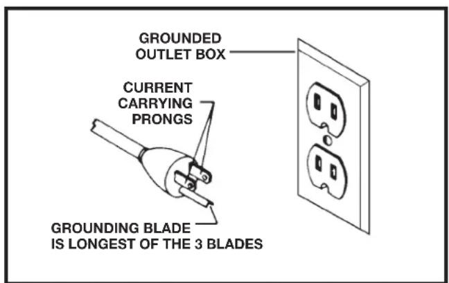
FIG. A FIG. B
EXTENSION CORDS
△CAUTION: extension cords. Make sure your extension cord is in good condition and is a 3-wire extension cord which has a 3-prong grounding type plug and matching receptacle which will accept the machine's plug. When using an extension cord, be sure to use one heavy enough to carry the current of the machine. An undersized cord will cause a drop in line voltage, resulting in loss of power and overheating. The table shows the correct gauge to use depending on the cord length. If in doubt, use the next heavier gauge. The smaller the gauge number, the heavier the cord.
| MINIMUM GAUGE EXTENSION CORDRECOMMENDED SIZES FOR USE WITH STATIONARY ELECTRIC MACHINES | |||
| Ampere Rating | Volts T | total Length of Cord in Feet | Gauge of Extension Cord |
| 0-6 | 120 | up to 25 | 18 AWG |
| 0-6 | 120 | 25-50 | 16 AWG |
| 0-6 | 120 | 50-100 | 16 AWG |
| 0-6 | 120 | 100-150 | 14 AWG |
| 6-10 | 120 | up to 25 | 18 AWG |
| 6-10 | 120 | 25-50 | 16 AWG |
| 6-10 | 120 | 50-100 | 14 AWG |
| 6-10 | 120 | 100-150 | 12 AWG |
| 10-12 | 120 | up to 25 | 16 AWG |
| 10-12 | 120 | 25-50 | 16 AWG |
| 10-12 | 120 | 50-100 | 14 AWG |
| 10-12 | 120 | 100-150 | 12 AWG |
| 12-16 | 120 | up to 25 | 14 AWG |
| 12-16 | 120 | 25-50 | 12 AWG |
| 12-16 | 120 | ||
| GREATER THAN 50 FEET NOT RECOMMENDED | |||
FIG. C
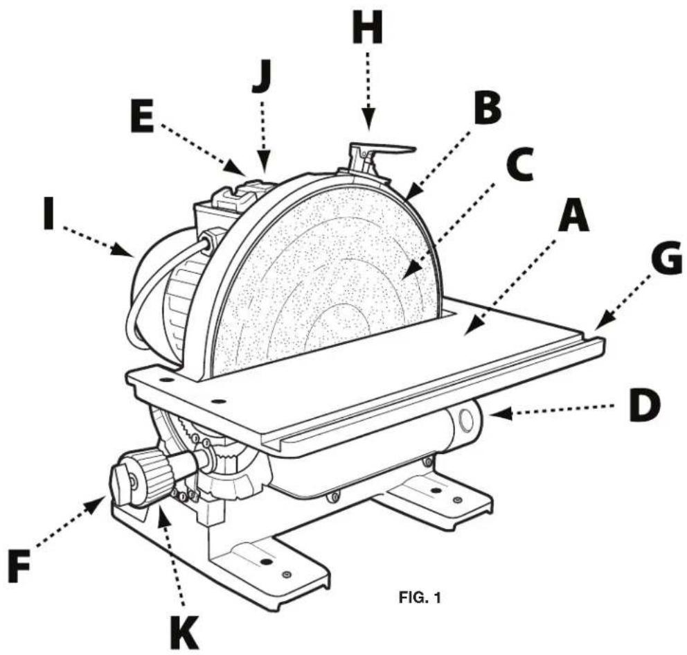
KEY FEATURES AND COMPONENTS
A. Cast iron tilting table
B. Disc plate
C. Sanding disc
D. 2 1/4" dust port
E. Power switch
F. Table locking wing nut
G. Miter gauge slot
H. Disc brake
I. 12 HP, 120V motor
J. Safety key
K. Table tilt adjustment knob
FUNCTIONAL DESCRIPTION
The DELTA ^® 12" Disc Sander is designed for sanding or polishing flat or beveled surfaces on wood and plastic materials.
PRODUCT SPECIFICATIONS
| Speed: 1725 RPM | |
| Disc Diameter: 12" | |
| Table Tilt: +45° to -45° | |
| Height: 15" | |
| Width: 17 1/4" | |
| Shipping Weight: 81 lbs | |
| Motor: 1⁄2 HP, 120 V, 1 Phase, 60 HZ | |
| Table Size: 17 1/4" x 6 1/4" | |
| Dust Collection Outlet: 2 1/4" | |
| Miter Gauge Groove: 3/8" x 3/4" | |
| Length: 17 3/4" | |
| Weight: 72 lbs |
UNPACKING
⚠ WARNING: The machine is heavy, be careful when removing it from the shipping container! Failure to comply may cause serious injury and/or damage to the sander and/or property!
Your DELTA 12" Disc Sander comes packed in a single container. Use a safety strap to avoid tip-over when lifting machine. Check shipping carton and machine for damage before unpacking.
Open the shipping container. Carefully remove packaging materials, parts and machine from shipping carton. Always check for and remove protective shipping materials around motors and moving parts. Lay out all parts on a clean work surface and check that all parts are present and in good condition:
DESCRIPTION (QUANTITY)
- 12" disc sander (1)
- Dust collection hose with 2 14 " port adaptor (1)
-
Brake lever assembly (1)
-
Miter gauge
• 2.5mm Allen wrench (1)
• 4mm Allen wrench (1)
Compare the items to inventory figures; verify that all items are accounted for before discarding the shipping box. Report any missing or damaged parts to your distributor or dealer. Prior to tool assembly and use, read this manual thoroughly to familiarize yourself with proper assembly, maintenance and safety procedures.
Remove any protective materials and coatings from all of the parts and the disc sander. The protective coatings can be removed by spraying WD-40 on them and wiping it off with a soft cloth. This may need redone several times before all of the protective coatings are removed completely
⚠ WARNING: If any parts are missing, do not attempt to plug in the power cord and turn "ON" the machine. The machine should only be turned "ON" after all the parts have been obtained and installed correctly.
ASSEMBLY
- Refer to Figure 2 and remove the 2 hex screws (A) from the disc housing using the 2.5mm Allen wrench supplied.
- Align the screw holes in the brake lever assembly (B) with the holes in the disc housing and secure using the hex screws removed in Step 1.
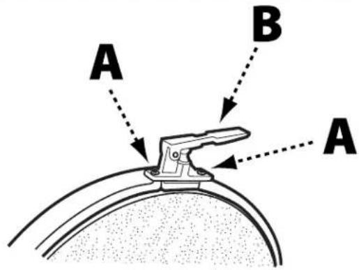
FIGURE 2
SECURE TOOL TO SUPPORTING SURFACE
Important: If during operation there is any tendency for the sander to tip over, slide or walk on the supporting surface, the sander must be secured to the supporting surface.
To secure the sander to the supporting surface, use screws or bolts and nuts through the four holes (A) as shown in Figure 3.
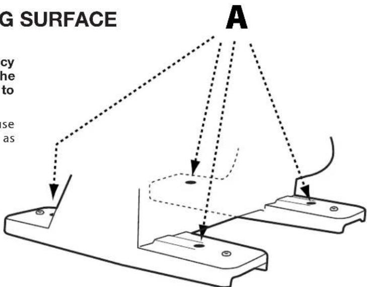
FIGURE 3
CONNECT DUST HOSE TO DUST COLLECTOR SYSTEM
The 12" Disc Sander has an efficient, integral fan which provides excellent dust collection. It is recommended that the machine be attached to a dust collector using the 2 1/4" dust port (A) shown in Figure 4.
If a dust collector is not available, insert one end of the supplied dust hose (B) into the dust port and place the other end of the dust hose into a garbage can or other receptacle.
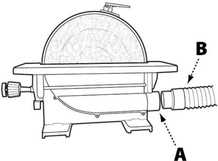
FIGURE 4
OPERATION
STARTING AND STOPPING SANDER
⚠CAUTION: Failure to read and understand the instructions, warnings and safety guidelines provided in this manual may lead to serious injury and / or damage to machine or the work piece.
⚠CAUTION: Be sure the sanding disc is securely installed onto the disc plate.
⚠️CAUTION: Make sure the table tilt locking levers are secured and that the table is locked in place at the desired angle or tilt.
⚠️CAUTION: Make sure the machine is installed on a flat, sturdy and stable surface able to support the weight of the machine and the work piece to be sanded.
NOTE: The DELTA ^® 12" Disc Sander uses a Safety Key (A), shown in Figure 5. The Safety Key must be in place in order to operate the machine. Before attempting to turn on the sander, ensure the Safety Key is installed.
- The ON/OFF switch (B) is located on the top of the motor. To turn the sander "ON", move the switch toward rear of sander.
- To turn the sander "OFF", move switch to the front position as shown.
NOTE: The sanding disc on this sander rotates counterclockwise. In order to prevent injury and produce good results, always sand on the left side of the table only. Never work on the right side of the table where the disc is rotating up as it is difficult to control the work piece.
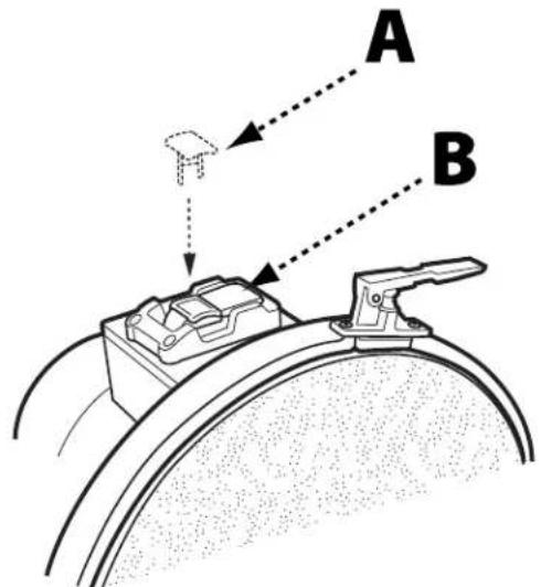
FIGURE 5
REMOVING THE SAFETY KEY TO LOCK SANDER
When the tool is not in use, the switch should be locked in the "OFF" position. This can be done by grasping the Safety Key (A), shown in Figure 5, and pulling it out of the switch. With the Safety Key removed the switch
will not operate. Should the Safety Key be removed while the machine is running, the switch can be turned "OFF" once, but cannot be restarted without inserting the Safety Key.
⚠ WARNING: Apply the brake when the switch is in the "off" position only. Applying the brake while switch is in the "on" position may damage the machine.
This 12" Disc Sander is equipped with a manual disc brake that brings the sanding disc to a safe stop once the power switch has been turned to the "OFF" position. The manual disc brake should only be used once the sander has been turned off. To apply the manual disc brake, press down on brake lever (A) as shown in Figure 6.
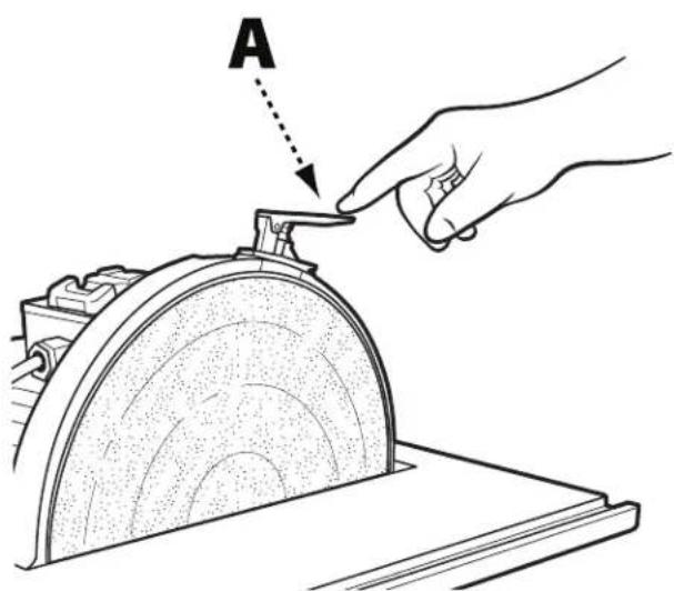
FIGURE 6
OPERATION
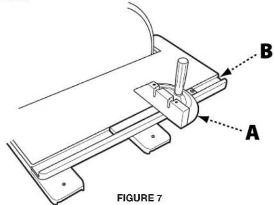
ANGLED AND END SANDING USING THE MITER GAUGE
The majority of work performed on the DELTA ^® 12" Disc Sander is usually accomplished using the table as a support. For accurate sanding of angled and end-grain surfaces, as shown in Figure 7, your disc sander comes with an adjustable miter gauge (A) and 3/8" x 3/4" t-slot (B) machined into the table. To use the provided miter gauge for angled or end-grain sanding, do the following:
▲CAUTION: make certain machine is disconnected from power source before making adjustments.
- Slide the miter gauge into the t-slot.
- Loosen the miter adjustment handle (C) by rotating it to the left and adjust the miter gauge to the desired sanding angle. Tighten the miter adjustment handle.
- Ensure the workpiece is positioned along the miter gauge before turning the machine on and starting to work.
BEVEL SANDING USING THE TABLE TILT
△CAUTION: Make certain machine is disconnected from power source before making adjustments.
The table can be tilted up to 45 degrees up or down. A scale (A), Figure 8, and pointer (B) are provided to indicate the degree of tilt. Ball-indent positive stops on the tilt adjustment indicator are located at 0°, 35°, and 45°.
To tilt the table up or down, loosen table locking wing nut (C) and rotate the knob (D). As the knob is rotated, the table will pivot either up or down. Turning the knob clockwise will make the table tilt downward. Turning the knob counterclockwise will tilt the table upward. Pivot the table until desired angle is established. Then tighten table locking wing nut.
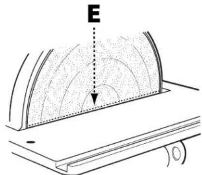
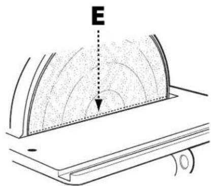
⚠️WARNING: Regardless of which position the table is tilted, the table edge (E), shown in Figure 10, must be no more than 1/16" from the sanding disc to avoid trapping the work or fingers between the table and sanding disc. To adjust the position of the table relative to the sanding disc, see "adjusting miter gauge slot alignment" on page 11.
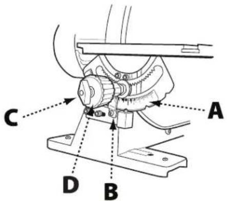
FIGURE 8
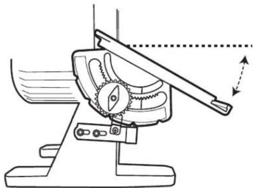
⚠ WARNING: We suggest that all bevel sanding applications be performed with the table tilted down as shown in Figure 9; however, if there is a need to tilt the table up, the workpiece must be securely fastened or clamped to a fixture or jig to prevent the workpiece from being torn from hands and becoming trapped between the table and sanding disc. See Figure 10.
natural_image
Technical line drawing of a mechanical device with gears and lever, showing motion direction (no text or symbols)FIGURE 9
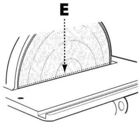
FIGURE 10
ADJUSTMENTS
ADJUSTING MITER GAGE SLOT ALIGNMENT
⚠️CAUTION: Make certain machine is disconnected from power source before making adjustments.
- Check to see if the miter gage slot (A), shown in Figure 11, is parallel with the disc by placing a combination square in the miter gage slot with one end of the square against the disc as shown.
• Using a pencil, make a mark on the abrasive disc where the square contacts the disc. - Rotate the disc 180^ and check the distance between the disc and miter gauge slot at the opposite end of the table. If an adjustment is necessary, proceed as follows:
NOTE: When making the following adjustment, ensure the table locking wing nut is tightened.
- Using the supplied hex wrench, loosen the four screws (B) indicated in Figure 12, which secure the table to the trunnions.
- Adjust the table by moving it in or out until the miter gage slot is equidistant from the disc at both ends of the table.
- Tighten the four screws securing the table to the trunnions.
⚠ WARNING: To avoid trapping the work or fingers between the table and sanding disc, the table edge should be positioned a maximum of 1/16" from the sanding disc.
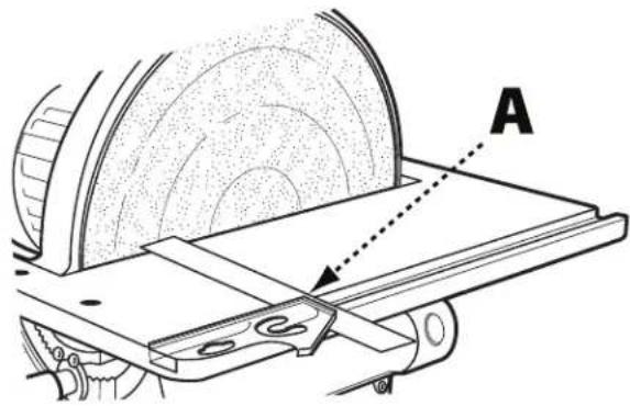
FIGURE 11
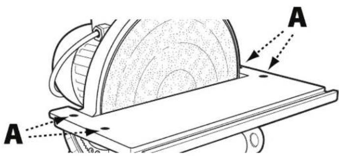
FIGURE 12
SQUARING TABLE TO THE SANDING DISC
▲CAUTION: Make certain machine is disconnected from power source before making adjustments.
- Referring to Figure 13, ensure table tilt indicator (A) is set to 0^ .
- Place an accurate square on the table with one end of the square against the disc. If the table is not square to the disc, proceed as follows:
- Loosen the table locking wing nut (B).
- Locate the 0^ set screw which is located beneath the table and loosen the retaining nut on the set screw.
- Rotate the 0^ set screw and re-measure using the square, repeating until the table is square with the abrasive disc.
- Once the table is square, retighten the retaining nut on the 0^ set screw.
- Tighten table locking wing nut.
- Re-calibrate table tilt indicator by loosening the indicator retaining screw and positioning the tilt indicator to the 0^ mark on the scale.
- Tighten indicator retaining screw.
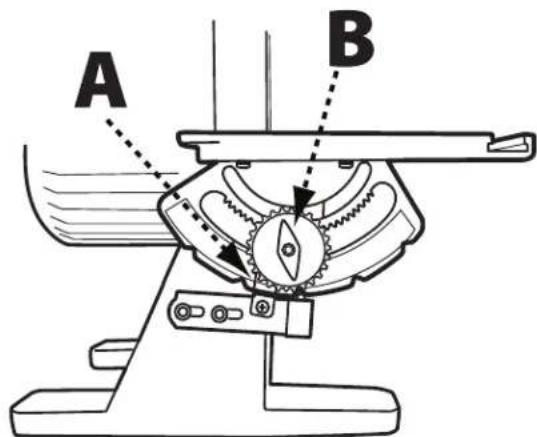
FIGURE 13
RECOMMENDED MAINTENANCE
NOTE: Disconnect machine from power source before performing any maintenance.
LUBRICATION
All bearings are sealed and permanently lubricated. No further lubrication is needed.
ROUTINE INSPECTION
It is recommended that you periodically inspect your spindle sander as a precautionary action. During this time, check for the following:
- Inspect all hardware, fittings and fasteners that may have loosened due to vibration and re-tighten as needed.
- Check for dust and/or wood particles that may have accumulated on or in the machine. Check all dust collection fittings – re-tighten as needed.
- Inspect the ON/OFF SWITCH for damage before each use. Periodically inspect the power cord and plug for damage. If necessary replace the power cord and the plug at the first signs of visible damage.
REPLACING THE SANDING DISC
⚠️CAUTION: Make certain machine is disconnected from power source.
- To remove sanding disc (A), simply peel old abrasive disc from machine as shown.
- To install a new abrasive disc, make sure the disc plate (B) is clean, dry, and free from any oil, grease, or old adhesive.
- Peel back half the adhesive backing from the new disc and slide between the table and disc plate so that the half without the backing is aligned with the top half of the disc plate.
- Press top half of sanding disc onto top half of disc plate.
- Manually rotate disc plate one-half turn, remove remainder of adhesive backing and firmly press sanding disc onto disc plate.
⚠ WARNING: Make certain the sanding disc is securely in position before connecting machine to a power source.
ACCESSORIES
A complete line of accessories is available from your DELTA ^® Supplier, DELTA ^® Factory Service Centers, and DELTA ^® Factory Service Centers, and DELTA ^® Authorized Service Centers. Please visit our Web Site www.DeltaMachinery.com for an online catalog or for the name or your nearest supplier.
⚠ WARNING: Since accessories other than those offered by DELTA® have not been tested with this product, use of such accessories could be hazardous. For safest operation, only DELTA® recommended accessories should be used with this product.
WARRANTY
To register your tool for warranty service visit our website at www.DeltaMachinery.com.
Five Year Limited New Product Warranty
DELTA® will repair or replace, at its expense and at its option, any new DELTA® machine, machine part, or machine accessory which in normal use has proven to be defective in workmanship or material, provided that the customer returns the product prepaid to a DELTA® factory service center or authorized service station with proof of purchase of the product within five years and provides DELTA® with reasonable opportunity to verify the alleged defect by inspection. For all refurbished DELTA® product, the warranty period is 180 days. DELTA® will not be responsible for any asserted defect which has resulted from normal wear, misuse, abuse or repair or alteration made or specifically authorized by anyone other than an authorized DELTA® service facility or representative. Under no circumstances will DELTA® be liable for incidental or consequential damages resulting from defective products. Some states do not allow the exclusion or limitation of incidental or consequential damages, so the above limitation or exclusion may not apply to you. This warranty is DELTA®'s sole warranty and sets forth the customer's exclusive remedy, with respect to defective products; all other warranties, express or implied, whether of merchantability, fitness for purpose, or otherwise, are expressly disclaimed by DELTA®. For further detail of warranty coverage and warranty repair information, visit www.DeltaMachinery.com or call 1-800-223-7278. This warranty gives you specific legal rights and you may have other rights which vary in certain states or provinces.
LATIN AMERICA: This warranty does not apply to products sold in Latin America. For products sold in Latin America, see country specific warranty information contained in the packaging, call the local company or see website for warranty information.
DELTA®
POWER EQUIPMENT CORPORATION
PARTS, SERVICE OR WARRANTY ASSISTANCE
All DELTA ^® Machines and accessories are manufactured to high quality standards and are serviced by a network of DELTA ^® Factory Service Centers and DELTA ^® Authorized Service Centers. To obtain additional information regarding your DELTA ^® quality product or to obtain parts, service, warranty assistance, or the location of the nearest service center, please call 1-800-223-7278.
REPLACEMENT PARTS
Use only identical replacement parts. For a parts list or to order parts, visit our website at www.DeltaMachinery.com. You can also order parts from your nearest factory-owned branch, Authorized Warranty Service Center or by calling Technical Service Manager at 1-800-223-7278 to receive personalized support from one of our highly-trained representatives.
FREE WARNING LABEL REPLACEMENT
If your warning labels become illegible or are missing, call 1-800-223-7278 for a free replacement.

SERVICE AND REPAIRS
All quality tools will eventually require servicing and/or replacement of parts. For information about DELTA * Power Equipment Corporation, its factory-owned branches, or to locate an Authorized Warranty Service Center, visit our website at www.DeltaMachinery.com or call our Customer Care Center at 1-800-223-7278. All repairs made by our service centers are fully guaranteed against defective material and workmanship. We cannot guarantee repairs made or attempted by others. By calling this number you can also find answers to most frequently asked questions.
You can also write to us for information at DELTA' Power Equipment Corporation, 2651 New Cut Road, Spartanburg, SC 29303 - Attention: Technical Service Manager. Be sure to include all of the information shown on the nameplate of your tool (model number, type, serial number, date code, etc.)
CONSIGNES DE SÉCURITÉ IMPORTANTES
AVERTISSEMENT
SPÉCIFICATIONS DU PRODUIT
natural_image
Technical line drawing of a mechanical device with gear and lever mechanism (no text or symbols)FIGURE 9
AJUSTEMENTS
RÉGLAGE DE L'ALIGNEMENT DE LA RAINURE POUR GUIDE À ONGLETS
ATTENTION:
FIGURE 12
AJUSTER LA TABLE PERPENDICULAIREMENT AU DISQUE DE PONÇAGE
ATTENTION:
SERVICE ET RÉPARATIONS
FIG. 1
FIGURE 4
OPERACIÓN
OPERACIÓN
LIJADO DE ÁREAS ANGULOSAS Y DE BORDES CON GUÍA DE INGLETE
natural_image
Technical line drawing of a mechanical device with gears and a lever, showing motion direction (no text or symbols)FIGURE 9
AJUSTES
FIGURE 12
SERVICIO TÉCNICO Y REPARACIONES
Spartanburg, South Carolina 29303
(800) 223-7278
www.DeltaMachinery.com
Copyright © 2013 DELTA Power Equipment Corporation DPEC001142 - 12-10-13
Revised: 02-04-16


- TABLE OF CONTENTS
- IMPORTANT SAFETY INSTRUCTIONS
- SAFETY GUIDELINES - DEFINITIONS
- DANGER:
- WARNING:
- CAUTION:
- CAUTION
- GENERAL SAFETY RULES
- FAILURE TO FOLLOW THESE RULES MAY RESULT IN SERIOUS INJURY.
- SAVE THESE INSTRUCTIONS.
- POWER CONNECTIONS
- DANGLE: OSE THE MACHINE TO RAIN OR OPERATE THE MACHINE IN DAMP LOCATIONS.
- MOTOR SPECIFICATIONS
- GROUNDING INSTRUCTIONS
- ▲ DANGER: THIS MACHINE MUST BE GROUNDED WHILE IN USE TO PROTECT THE OPERATOR FROM ELECTRIC SHOCK.
- All grounded, cord-connected machines:
- A DANGERES, MAKE CERTAIN THE RECEPTACLE IN QUESTION IS PROPERLY GROUNDED. IF YOU ARE NOT SURE, HAVE A QUALIFIED ELECTRICIAN CHECK THE RECEPTACLE.
- EXTENSION CORDS
- KEY FEATURES AND COMPONENTS
- FUNCTIONAL DESCRIPTION
- UNPACKING
- DESCRIPTION (QUANTITY)
- ASSEMBLY
- SECURE TOOL TO SUPPORTING SURFACE
- CONNECT DUST HOSE TO DUST COLLECTOR SYSTEM
- OPERATION
- STARTING AND STOPPING SANDER
- REMOVING THE SAFETY KEY TO LOCK SANDER
- ANGLED AND END SANDING USING THE MITER GAUGE
- ▲CAUTION: make certain machine is disconnected from power source before making adjustments.
- BEVEL SANDING USING THE TABLE TILT
- △CAUTION: Make certain machine is disconnected from power source before making adjustments.
- ADJUSTMENTS
- ADJUSTING MITER GAGE SLOT ALIGNMENT
- ⚠️CAUTION: Make certain machine is disconnected from power source before making adjustments.
- ⚠ WARNING: To avoid trapping the work or fingers between the table and sanding disc, the table edge should be positioned a maximum of 1/16" from the sanding disc.
- SQUARING TABLE TO THE SANDING DISC
- RECOMMENDED MAINTENANCE
- LUBRICATION
- ROUTINE INSPECTION
- REPLACING THE SANDING DISC
- ⚠️CAUTION: Make certain machine is disconnected from power source.
- ⚠ WARNING: Make certain the sanding disc is securely in position before connecting machine to a power source.
- ACCESSORIES
- WARRANTY
- Five Year Limited New Product Warranty
- DELTA®
- POWER EQUIPMENT CORPORATION
- PARTS, SERVICE OR WARRANTY ASSISTANCE
- REPLACEMENT PARTS
- FREE WARNING LABEL REPLACEMENT
- SERVICE AND REPAIRS
- CONSIGNES DE SÉCURITÉ IMPORTANTES
- AVERTISSEMENT
- SPÉCIFICATIONS DU PRODUIT
- AJUSTEMENTS
- RÉGLAGE DE L'ALIGNEMENT DE LA RAINURE POUR GUIDE À ONGLETS
- ATTENTION:
- AJUSTER LA TABLE PERPENDICULAIREMENT AU DISQUE DE PONÇAGE
- SERVICE ET RÉPARATIONS
- OPERACIÓN
- LIJADO DE ÁREAS ANGULOSAS Y DE BORDES CON GUÍA DE INGLETE
- AJUSTES
- SERVICIO TÉCNICO Y REPARACIONES
Brand : DELTA
Model : 31‑140
Category : Sander