
31-484 - Sander DELTA - Free user manual and instructions
Find the device manual for free 31-484 DELTA in PDF.

| Product Type | Floor-Standing Oscillating Spindle Sander |
| Brand | DELTA |
| Model | 31-484 |
| Power Supply Voltage | 120/240 V, 60 Hz |
| Circuit Rating | 20 A (time-delay fuse) |
| Motor | Alternating Current, 1 Phase |
| Spindle Tilt Angle | 0° to 45° |
| Spindle Diameters | 6.4 mm (1/4"), 9.5 mm (3/8"), 12.7 mm (1/2"), 15.9 mm (5/8"), 19.1 mm (3/4"), 25.4 mm (1"), 38.1 mm (1-1/2"), 50.8 mm (2"), 76.2 mm (3"), 101.6 mm (4") |
| Table Type | Cast Iron with Interchangeable Inserts |
| Number of Table Inserts | 6 (3 oblong, 3 round) |
| Dust Port | 101.6 mm (4 in) |
| Usable Materials | Wood and Plastic |
| Gear Oil | SAE 90, change every 800 h |
| Bearings | Sealed, Maintenance-Free |
| Warranty | 5-Year Limited |
| Weight | Heavy (requires two people for unpacking) |
| Included Accessories | 10 spindles with sleeves, 6 inserts, 2 open-end wrenches, tilt wheel, locking knob, storage hooks, hex wrenches |
| Safety | Grounding, emergency stop switch with handle, tilt lock |
| Maintenance | Check fasteners, clean dust, change oil every 800 h |
Frequently Asked Questions - 31-484 DELTA
User questions about 31-484 DELTA
0 question about this device. Answer the ones you know or ask your own.
Ask a new question about this device
Download the instructions for your Sander in PDF format for free! Find your manual 31-484 - DELTA and take your electronic device back in hand. On this page are published all the documents necessary for the use of your device. 31-484 by DELTA.
USER MANUAL 31-484 DELTA
natural_image
Line drawing of a mechanical device with labeled components including a stop button and tool holder (no text or symbols present)Français (16)
Español (31)
www.DeltaMachinery.com
Instruction Manual
IMPORTANT SAFETY INSTRUCTIONS....2
SAFETY GUIDELINES - DEFINITIONS....3
GENERAL SAFETY RULES 3
POWER CONNECTIONS....5
Motor Specifications 5
Grounding Instructions ....5
Extension Cords 6
FEATURES AND COMPONENTS....6
FUNCTIONAL DESCRIPTION....6
PRODUCT SPECIFICATIONS....7
UNPACKING 7
ASSEMBLY 8
Attach the Motor Cover....8
Attach the Spindle Tilt Wheel....8
Attach Storage Hooks....8
Install Sanding Sleeves onto Spindles....9
Install the Spindle onto the Sander....9
Select and Install the Table Insert....10
Square the Table to the Spindle 11
Connect to a Dust Collector 11
OPERATION 12
ADJUSTMENTS....13
Adj ust the Spindle Tilt....13
Adjust The 90° and 45° Positive Stops....13
RECOMMENDED MAINTENANCE....14
Routine Inspection....14
Bearings....14
Changing the Gear Oil....14
ACCESSORIES....14
SERVICE AND REPAIRS......14
WARRANTY 15
REPLACEMENT PARTS....15
FRANÇAIS....16
ESPAÑOL....31
IMPORTANT SAFETY INSTRUCTIONS
⚠ WARNING: READ AND UNDERSTAND ALL WARNINGS AND OPERATING INSTRUCTIONS BEFORE USING THIS EQUIPMENT. Failure to follow all instructions listed below, may result in electric shock, fire, and/or serious personal injury or property damage.
Woodworking can be dangerous if safe and proper operating procedures are not followed. As with all machinery, there are certain hazards involved with the operation of the product. Using the machine with respect and caution will considerably lessen the possibility of personal injury. However, if normal safety precautions are overlooked or ignored, personal injury to the operator may result. Safety equipment such

as guards, push sticks, hold-downs, featherboards, goggles, dust masks and hearing protection can reduce your potential for injury. But even the best guard won't make up for poor judgment, carelessness or inattention. Always use common sense and exercise caution in the workshop. If a procedure feels dangerous, don't try it. Figure out an alternative procedure that feels safer. REMEMBER: Your personal safety is your responsibility. For additional information please visit our website www.DeltaMachinery.com.
⚠ WARNING: This machine was designed for certain applications only. DELTA® Power Equipment Corporation strongly recommends that this machine not be modified and/or used for any application other than that for which it was designed. If you have any questions relative to a particular application, DO NOT use the machine until you have first contacted DELTA® to determine if it can or should be performed on the product.
If you have any questions relative to its application DO NOT use the product until you have written DELTA® Power Equipment Corporation and we have advised you. Contact us online at www.DeltaMachinery.com or by mail at Technical Service Manager, DELTA® Power Equipment Corporation, 2651 New Cut Road, Spartanburg, SC 29303.
Information regarding the safe and proper operation of this tool is available from the following sources:
• Power Tool Institute, 1300 Sumner Avenue, Cleveland, OH 44115-2851 or online at www.powertoolinstitute.com
• National Safety Council, 1121 Spring Lake Drive, Itasca, IL 60143-3201
- American National Standards Institute, 25 West 43rd Street, 4 floor, New York, NY 10036 www.ansi.org - ANSI 01.1 Safety Requirements for Woodworking Machines
• U.S. Department of Labor regulations www.osha.gov
SAFETY GUIDELINES - DEFINITIONS
This manual contains information that is important for you to know and understand. This information relates to protecting YOUR SAFETY and PREVENTING EQUIPMENT PROBLEMS. To help you recognize this information, we use the symbols below. Please read the manual and pay attention to these sections.
▲DANGER: Indicates an imminently hazardous situation which, if not avoided, will result in death or serious injury.
⚠ WARNING: Indicates a potentially hazardous situation which, if not avoided, could result in death or serious injury.
▲CAUTION: Indicates a potentially hazardous situation which, if not avoided, may result in minor or moderate injury.
CAUTION Used without the safety alert symbol indicates potentially hazardous situation which, if not avoided, may result in property damage.
GENERAL SAFETY RULES
⚠ WARNING: WARNING FAILURE TO FOLLOW THESE RULES MAY RESULT IN SERIOUS PERSONAL INJURY.
FOR YOUR OWN SAFETY, READ AND UNDERSTAND THE INSTRUCTION MANUAL BEFORE OPERATING THE UNIT. Learn the unit's application and limitations as well as the specific hazards peculiar to it.
- KEEP WORK AREA CLEAN. Cluttered areas and benches invite accidents.
- DON'T USE IN DANGEROUS ENVIRONMENT. Don't use this unit in damp or wet locations, or expose it to rain. Keep work area well-lighted.
- KEEP CHILDREN AND VISITORS AWAY. All children and visitors should be kept a safe distance from work area.
• DISCONNECT UNIT before servicing.
- CHECK DAMAGED PARTS. Before further use of the unit, properly repair or replace any part that is damaged.
⚠ WARNING: FAILURE TO FOLLOW THESE RULES MAY RESULT IN SERIOUS INJURY.
- Read and understand the warnings posted on the machine and in this manual. Failure to comply with all of these warnings may cause serious injury.
- Replace the warning labels if they become obscured or removed.
- This machine is designed and intended for use by properly trained and experienced personnel only. If you are not familiar with the proper and safe operation of a heavy duty floor spindle sander, do not use until proper training and knowledge have been obtained.
- Do not use this machine for other than its intended use. If used for other purposes, DELTA® Power Equipment Corporation disclaims any real or implied warranty and holds itself harmless from any injury that may result from that use.
- Always wear approved safety glasses/face shields while using this spindle sander.
- Before operating this sander, remove tie, rings, watches and other jewelry, and roll sleeves up past the elbows. Remove all loose clothing and confine long hair. Non-slip footwear or anti-skid floor strips are recommended. Do not wear gloves.
-
Wear ear protectors (plugs or muffs) during extended periods of operation.
-
Some dust created by power sanding, sawing, grinding, drilling and other construction activities contain chemicals known to cause cancer, birth defects or other reproductive harm. Some examples of these chemicals are:
- Lead from lead based paint.
- Crystalline silica from bricks, cement and other masonry products.
- Arsenic and chromium from chemically treated lumber.
Your risk of exposure varies, depending on how often you do this type of work. To reduce your exposure to these chemicals, work in a well-ventilated area and work with approved safety equipment, such as face or dust masks that are specifically designed to filter out microscopic particles.
- Do not operate this machine while tired or under the influence of drugs, alcohol or any medication.
- Make certain the switch is in the OFF position before connecting the machine to the power source.
- Make certain the machine is properly grounded.
-
Make all machine adjustments or maintenance with the machine unplugged from the power source.
-
Form a habit of checking to see that all extra equipment such as adjusting keys, wrenches, scrap, stock, and cleaning rags are removed away from the machine before turning on.
- Keep safety guards in place at all times when the machine is in use. If removed for maintenance purposes, use extreme caution and replace the guards immediately when maintenance is complete.
- Make sure the tool is firmly secured to the floor before use.
- Check damaged parts. Before further use of the machine, a guard or other part that is damaged should be carefully checked to determine that it will operate properly and perform its intended function. Check for alignment of moving parts, binding of moving parts, breakage of parts, mounting and any other conditions that may affect its operation. A guard or other part that is damaged should be properly repaired or replaced.
- Provide for adequate space surrounding work area and non-glare, overhead lighting.
- Keep the floor around the machine clean and free of scrap material, oil and grease.
- Keep visitors a safe distance from the work area. Keep children away.
- Make your workshop child proof with padlocks, master switches or by removing starter keys.
- Give your work undivided attention. Looking around, carrying on a conversation and "horse-play" are careless acts that can result in serious injury.
- Maintain a balanced stance at all times so that you do not fall or lean against the tool or its moving parts. Do not overreach or use excessive force to perform any machine operation.
-
Use the right tool at the correct speed and feed rate. Do not force a tool or attachment to do a job for which it was not designed. The right tool will do the job better and safer.
-
Use recommended accessories; improper accessories may be hazardous.
- Maintain machinery with care. Follow instructions for lubricating and changing accessories.
- Turn off the machine before cleaning. Use a brush or compressed air to remove dust or debris — do not use your hands.
- Do not stand on the machine. Serious injury could occur if the machine tips over.
- Never leave the machine running unattended. Turn the power off and do not leave the machine until it comes to a complete stop.
- At all times, hold the stock firmly.
- Always turn the sander on and allow it to come up to full speed before allowing the workpiece to contact the sanding surface.
- Make sure to use the appropriate size table insert for the sanding spindle selected.
- Do not use this machine for other than it intended use. If used for other purposes, DELTA® Power Equipment Corporation disclaims any real or implied warranty and holds itself harmless for any injury or damage which may result from that use.
Familiarize yourself with the following safety notices used in this manual:
CAUTION:
This means that if precautions are not heeded, it may result in minor injury and/or possible machine damage.
WARNING:
This means that if precautions are not heeded, it may result in serious injury or possibly even death.
SAVE THESE INSTRUCTIONS.
Refer to them often and use them to instruct others.
POWER CONNECTIONS
A separate electrical circuit should be used for your machines. This circuit should not be less than #12 wire and should be protected with a 20 Amp time lag fuse. If an extension cord is used, use only 3-wire extension cords which have 3-prong grounding type plugs and matching receptacle which will accept the machine's plug. Before connecting the machine to the power line, make sure the switch (s) is in the "OFF" position and be sure that the electric current is of the same characteristics as indicated on the machine. All line connections should make good contact. Running on low voltage will damage the machine.
DONGER EXPOSE THE MACHINE TO RAIN OR OPERATE THE MACHINE IN DAMP LOCATIONS.

FIG. A FIG. B
MOTOR SPECIFICATIONS
Your machine is wired for 115 volts, 60 HZ alternating current. Before connecting the machine to the power source, make sure the switch is in the “OFF” position.
GROUNDING INSTRUCTIONS
▲DANGER: THIS MACHINE MUST BE GROUNDED WHILE IN USE TO PROTECT THE OPERATOR FROM ELECTRIC SHOCK.
1. All grounded, cord-connected machines:
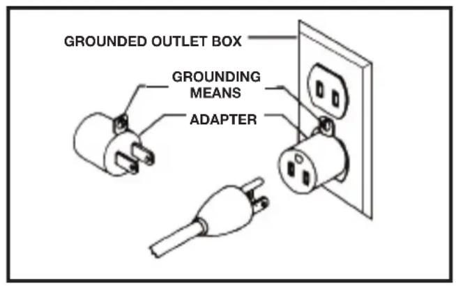
In the event of a malfunction or breakdown, grounding provides a path of least resistance for electric current to reduce the risk of electric shock. This machine is equipped with an electric cord having an equipment-grounding conductor and a grounding plug. The plug must be plugged into a matching outlet that is properly installed and grounded in accordance with all local codes and ordinances.
Do not modify the plug provided - if it will not fit the outlet, have the proper outlet installed by a qualified electrician.
Improper connection of the equipment-grounding conductor can result in risk of electric shock. The conductor with insulation having an outer surface that is green with or without yellow stripes is the equipment-grounding conductor. If repair or replacement of the electric cord or plug is necessary, do not connect the equipment-grounding conductor to a live terminal.
Check with a qualified electrician or service personnel if the grounding instructions are not completely understood, or if in doubt as to whether the machine is properly grounded.
Use only 3-wire extension cords that have 3-prong grounding type plugs and matching 3-conductor receptacles that accept the machine's plug, as shown in Fig. A.
Repair or replace damaged or worn cord immediately.
IN ALL CASES, MAKE CERTAIN THE RECEPTACLE IN QUESTION IS PROPERLY GROUNDED. IF YOU ARE NOT SURE, HAVE A QUALIFIED ELECTRICIAN CHECK THE RECEPTACLE.
EXTENSION CORDS
A CAUTION: per extension cords.
Make sure your extension cord is in good condition and is a 3-wire extension cord which has a 3-prong grounding type plug and matching receptacle which will accept the machine's plug. When using an extension cord, be sure to use one heavy enough to carry the current of the machine. An undersized cord will cause a drop in line voltage, resulting in loss of power and overheating. The table shows the correct gauge to use depending on the cord length. If in doubt, use the next heavier gauge. The smaller the gauge number, the heavier the cord.
| MINIMUM GAUGE EXTENSION CORDRECOMMENDED SIZES FOR USE WITH STATIONARY ELECTRIC MACHINES | |||
| Ampere Rating | Volts T | Total Length of Cord in Feet | Gauge of Extension Cord |
| 0-6 | 120 | up to 25 | 18 AWG |
| 0-6 | 120 | 25-50 | 16 AWG |
| 0-6 | 120 | 50-100 | 16 AWG |
| 0-6 | 120 | 100-150 | 14 AWG |
| 6-10 | 120 | up to 25 | 18 AWG |
| 6-10 | 120 | 25-50 | 16 AWG |
| 6-10 | 120 | 50-100 | 14 AWG |
| 6-10 | 120 | 100-150 | 12 AWG |
| 10-12 | 120 | up to 25 | 16 AWG |
| 10-12 | 120 | 25-50 | 16 AWG |
| 10-12 | 120 | 50-100 | 14 AWG |
| 10-12 | 120 | 100-150 | 12 AWG |
| 12-16 | 120 | up to 25 | 14 AWG |
| 12-16 | 120 | 25-50 | 12 AWG |
| 12-16 | 120 | ||
| GREATER THAN 50 FEET NOT RECOMMENDED | |||
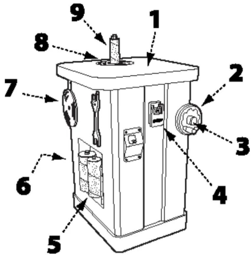
KEY FEATURES AND COMPONENTS
- Cast iron table
- Spindle tilt wheel
- Spindle tilt lock
- Power switch
- Spindle storage
- 4" Dust port (not visible)
- Table insert storage
- Interchangeable table insert
- Tilting sanding spindle
FUNCTIONAL DESCRIPTION
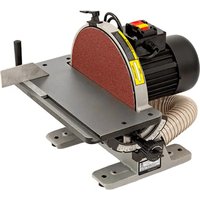
The DELTA ^® Heavy Duty Oscillating Floor Spindle Sander is designed for sanding or polishing flat, round, or curved surfaces on wood, plastic materials.
PRODUCT SPECIFICATIONS
| Oscillation rate 60 Strokes Per Minute (SPM) | |
| Oscillation stroke 1-1/2" | |
| Spindle Speed 1725 RPM | |
| Motor 1 HP, 110V, 10 Amps | |
| Table Size 24 – 5/8" X 24 – 1/2" | |
| Spindle Tilt 0° - 45° | |
| Spindle Size Range 1/4", 3/8", 1/2", 5/8", 3/4", 1", 1-1/2", 2", 3", 4" | |
| Dust Chute 4" | |
| Base Dimensions 24 – 3/4" X 19 – 3/4" | |
| NET Weight 374 Lbs |
UNPACKING
⚠ WARNING: The machine is heavy, be careful when removing it from the shipping container! Failure to comply may cause serious injury and/or damage to the tool and/or property!
⚠ WARNING: This step requires two adults. The machine is heavy, be careful when removing it from the shipping container! Failure to comply may cause serious injury and/or damage to the machine and/or property!
Your DELTA® Heavy Duty Oscillating Floor Spindle Sander comes packed in a single container. Use a safety strap to avoid tip-over when lifting machine. Check shipping carton and machine for damage before unpacking.
- Carefully cut the banding straps and remove them from the container.
- Cut along the tape line at the top of the container.
- Remove any loose parts accessible from the top of the container and set aside.
- Cut vertically along each of the four sides of the container to fully expose the machine.
- Remove any loose parts or hardware and set aside.
- With the help of a second adult, carefully lift the machine off the pallet and onto a level floor surface.
- Compare all parts to the list below and check that all parts are present and in good condition.
DESCRIPTION (QUANTITY)
• Floor spindle sander (1)
- Motor cover (1)
- Steel spindles and sanding sleeves (4) (Diameter - 1/4", 3/8", 1/2", 5/8")
- Rubber spindles and sanding sleeves (6) (Diameter - 3/4", 1", 1-1/2", 2", 3", 4")
- Oblong table inserts (3 (small, medium, large)
- Round table inserts (3) (small, medium, large)
- Open end spindle wrenches (2
- Storage hooks (2)
- Spindle tilt wheel (1)
- Spindle tilt retaining knob (1)
- Hardware package (1)
- Owner's manual (1) (not shown)
CONTENTS OF HARDWARE PACKAGE
• 3mm Hex Wrench (1)
- 4mm Hex Wrench (1)
- 6mm Hex Wrench (1)
• 12mm Open Wrench (1)
Report any missing or damaged parts to your distributor or dealer. Prior to tool assembly and use, read this manual thoroughly to familiarize yourself with proper assembly, maintenance and safety procedures.
Remove any protective materials and coatings from all of the parts and the sander. The protective coatings can be removed by spraying WD-40 on them and wiping it off with a soft cloth. This may need redone several times before all of the protective coatings are removed completely.
⚠ WARNING: If any parts are missing, do not attempt to plug in the power cord and turn “ON” the machine. The machine should only be turned “ON” after all the parts have been obtained and installed correctly.
ASSEMBLY
ATTACH THE MOTOR COVER
See Figure 1
- Slide the hinge pins (A) in the motor cover into the hinge holes located on the motor housing.
- Carefully press in the left side of the motor cover until the knob (B) engages in the opening.
- Tighten the lock knob on the motor cover.

FIGURE 1
ATTACH THE SPINDLE TILT WHEEL
See Figure 2
- Place the spindle tilt wheel (A) over the threaded shank by aligning the slot in the spindle tilt wheel with the pin in the shank.
- Attach the knurled spindle tilt retaining knob (B) by screwing it onto the shank.
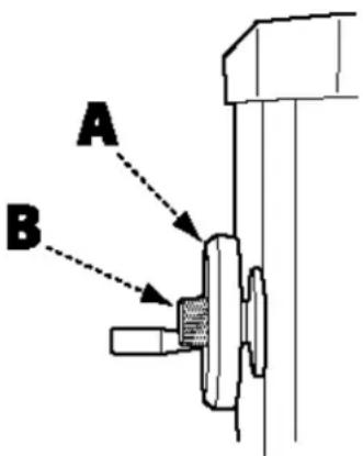
FIGURE 2
ATTACH STORAGE HOOKS
See Figure 3
To protect sanding spindle assemblies and the table inserts, it is recommended that you use the on-board storage to keep them safely out of the way and within easy reach.
The six table inserts and two spindle wrenches can be stored on the left side of the machine. Attach the two storage hooks (A) to the machine using two M5 X 15 Phillips round head screws.
The ten spindle assemblies can be stored in the fitted compartments on either side of the machine.
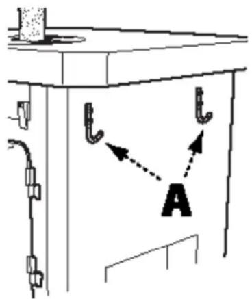
FIGURE 3
ASSEMBLY
INSTALL SANDING SLEEVES ONTO SPINDLES
6" Steel Spindles
See Figure 4
- Loosen the small clamping set screw (A) located at the base of the spindle.
- Slide the sanding sleeve onto the spindle completely, ensuring the sleeve slides into the recess located at bottom of spindle. Ensure the set screw is not hindering the seating of the sanding sleeve and that the sleeve is completely seated.
- Re-tighten the set screw to secure the sleeve in place
- To ensure the sleeve is secure on the spindle, pull on the sleeve to make sure it does not slide.
⚠️CAUTION: Do not over tighten the set screw as it may damage the sanding sleeve and can cause the sleeve to come off the spindle during use.

FIGURE 4
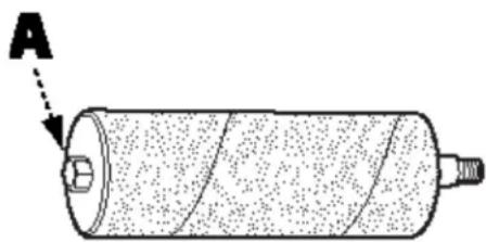
9" Steel Spindles
See Figure 5
- Slide the sanding sleeve onto the spindle, ensuring the bottom edge of the sleeve is even with the bottom edge of the spindle.
- Using the open end spindle wrench supplied, tighten the nut (A) on the top of the spindle.
- To ensure the sleeve is secure on the spindle, pull on it. If the sleeve slides on the spindle, continue tightening the nut at the top in 12 -turn increments as needed.
natural_image
Diagram of a cylindrical object with internal layered structure and labeled point A (no text or symbols beyond label)FIGURE 5
INSTALL THE SPINDLE ONTO THE SANDER
See Figure 6
⚠️CAUTION: Make sure that the switch is in "OFF" position and that the power cord is unplugged.
- Screw the threaded end of the spindle into the spindle seat and hand tighten.
- Open the rear access panel (A).
- Use the two open end spindle wrenches (supplied), one on the spindle and the other on the spindle seat as shown in Figure 6, to tighten.
NOTE: Do not over tighten the spindle as this can make it difficult to remove later.
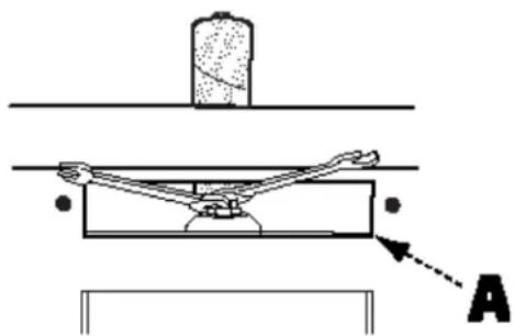
FIGURE 6
ASSEMBLY
SELECT AND INSTALL THE TABLE INSERT
⚠️CAUTION: Failure to use the proper insert with the corresponding spindle may result in injury and/or damage to the machine or the work piece.
Your DELTA ^® Heavy Duty Oscillating Floor Spindle Sander comes with six table inserts. The table inserts with the round openings are designed for sanding jobs where the spindle is in the fully upright (90°) position. The table inserts with the oblong openings are for beveled sanding.
- Using the recommended table inserts shown in Figure 7, select the desired table insert.
- Slip the table insert over the spindle. Ensure the table insert is properly seated by aligning the small notch in the table insert (A) with the corresponding small tab (B) in the table as shown in Figure 8.
| 31-484 INSERT/SPINDLE CHART | ||
| INSERT TO USE | ||
| SPINDLE DIAMETER | FOR 0° FOR | 45° |
| 4" E F | ||
| 3" D E | ||
| 2" D D | ||
| 1 1/2" C C | ||
| 1" B C | ||
| 3/4" B B | ||
| 5/8" A B | ||
| 1/2" A B | ||
| 3/8" A B | ||
| 1/4" A A | ||

natural_image
Abstract black-and-white circular graphic with concentric arcs and a dot (no text or symbols)A

natural_image
Black and white icon of a CD or DVD disc with concentric rings (no text or symbols)B

natural_image
Abstract black-and-white circular graphic with concentric arcs and a central hole (no text or symbols)C

natural_image
Abstract black-and-white circular graphic with concentric arcs and a central hole, no text or symbols present.D

natural_image
Simple black circular shape on white background with no text or symbolsE

natural_image
Simple black circular shape with no text or symbolsFIGURE 7
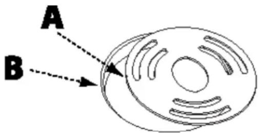
FIGURE 8
ASSEMBLY
To ensure proper operation and consistent results, the spindle must be square to the table surface. To check the alignment
- Make sure the spindle tilt indicator is at 90°. If necessary, see instructions for "Adjusting the Spindle Tilt" on page 13 and reposition the spindle to 90°.
- Use a square with one side flush against the spindle and the other side resting on the table surface to check the alignment of the table relative to the spindle.
If the table is out of square, you must adjust the 90^ positive stop. Refer to Figure 9 and do the following:
- Unlock the lock knob on the motor cover (Figure 1 on page #) and open the cover.
- Locate the 90^ positive stop collar (A) on the long threaded rod (B) that runs front to back on the left side of the machine.
NOTE: There are two stop collars located on the threaded rod. The collar furthest to the rear of the machine is the 90^ positive stop collar.
- Loosen the 2 set screws on the 90° positive stop collar, using a 3mm hex wrench.
- Rotate the 90^ positive stop collar, re-tighten the set screws and re-measure the table alignment, repeating steps 2 and 3 if necessary until table and spindle are in square.
- Adjust the spindle tilt indicator to read 90° by unscrewing the four Phillips head screws securing the tilt indicator window to the cabinet and removing the window. Loosen the tilt arrow retaining screw, reposition the arrow, re-tightening the retaining screw.
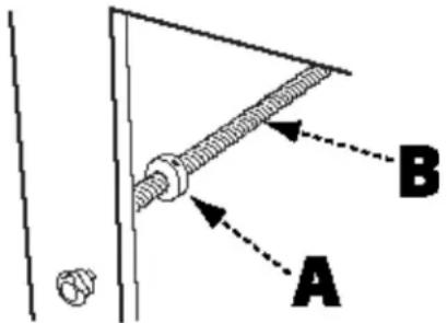
FIGURE 9
CONNECT TO A DUST COLLECTOR
The spindle sander creates a large amount of dust while in use. It is strongly recommended that you connect the spindle sander to a dust collector. Your DELTA® Heavy Duty Oscillating Floor Spindle Sander is equipped with a 4" dust port which is located at the bottom in the rear of the machine. This must be connected to dust collector hoses to ensure safe operation.
⚠ WARNING: Do not attempt to operate this tool without first connecting it to an adequate dust collection system.
⚠ WARNING: Always turn on the dust collector before starting the sander and always stop the sander before turning off the dust collector.
OPERATION
CAUTION:
Failure to read and understand the instructions, warnings and safety guidelines provided in this manual may lead to serious injury and / or damage to machine or the work piece.
CAUTION:
Be sure the sanding spindle is securely installed in the machine.
CAUTION:
Make sure the spindle tilt lock is secured and that the spindle is locked in place at the desired angle or tilt.
CAUTION:
Make sure the machine is installed on a flat, sturdy and stable surface able to support the weight of the machine and the work piece to be sanded.
See Figure 10.
- Select and install the desired sanding spindle with the corresponding table insert (see page 10).
- Ensure the spindle is at the correct sanding angle (page 13) and that the spindle position is locked in place.
- To start the machine, lift the red the safety paddle (A) and push the green "START" button. Wait for the spindle to reach full speed before sanding.
- Hold the work piece firmly and work from a stable standing position. When the spindle is fully vertical (90°), you may sand from any part of the table. When the spindle is tilted make sure the work piece is positioned on the front half of the table.
- To achieve the best finish results and to ensure maximum sanding sleeve life, slowly move the work piece back and forth across the entire surface of the sanding spindle
- To stop the machine, push the red "Stop" button and wait for the spindle to come to a complete stop.
Using the Safety Paddle: Your DELTA® Heavy Duty Oscillating Floor Spindle Sander is equipped with an emergency stop safety paddle, enabling you to easily shut off the machine. To use the Safety Paddle simple depress the paddle.
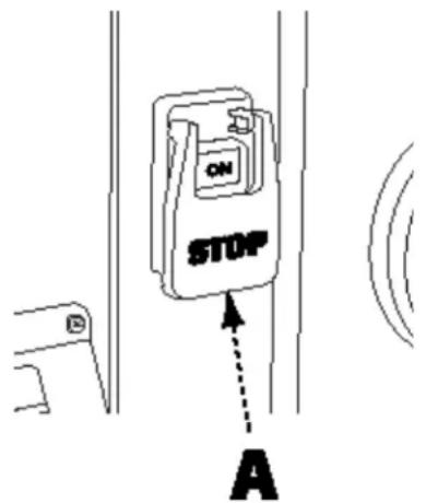
FIGURE 10
ADJUSTMENTS
ADJUST THE SPINDLE TILT
See Figure 11
⚠️CAUTION: For any bevel sanding operation, you must use a table insert with an oblong-shaped opening. Failure to do so may lead to serious injury and / or damage to machine or the work piece.
- Loosen the spindle tilt lock knob (A).
- Rotate the spindle tilt wheel (B), using the tilt indicator (C) for reference.
- Once the spindle is at the desired angle, re-tighten the spindle tilt lock knob.
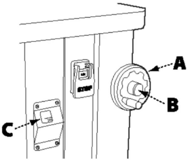
FIGURE 11
ADJUST THE 90° AND 45° POSITIVE STOPS
See Figure 6
To adjust the 90° positive stop, see the section "SQUARE THE TABLE TO THE SPINDLE" on page 11.
To adjust the 45^ positive stop, refer to Figure 12 and do the following:
NOTE: The 90° stop must be adjusted and squared to table BEFORE the 45° stop can be adjusted.
- Verify the spindle is square to the table surface and the tilt indicator is set to 90^ .
- Unlock the spindle tilt lock knob and rotate the spindle tilt wheel until the tilt indicator reaches 45^ .
- Locate and remove the rubber access plug (A) on the right side of the machine.
- Using a 3 mm Allen wrench, loosen the 2 set screws on the 45^ positive stop collar (B).
- Hold the collar in place with the wrench and rotate the spindle tilt wheel. This will reposition the 45^ positive stop collar on the threaded rod.
- Using a measuring triangle, check the angle of the spindle to the table, repeating step 4 above until the spindle is at a 45^ angle to the table.
- Tighten the 45^ positive stop collar set screw and replace the access plug.
- Lock the spindle tilt lock knob.
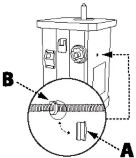
FIGURE 12
RECOMMENDED MAINTENANCE
ROUTINE INSPECTION
It is recommended that you periodically inspect your spindle sander as a precautionary action. During this time, check for the following:
- Inspect all hardware, fittings and fasteners that may have loosened due to vibration and re-tighten as needed.
- Check for dust and/or wood particles that may have accumulated on or in the machine. Check all dust collection fittings – re-tighten as needed.
- Inspect the ON/OFF SWITCH for damage before each use. Periodically inspect the power cord and plug for damage. If necessary replace the power cord and the plug at the first signs of visible damage.
- Check all table inserts, spindles and sanding sleeves for damage and replace if necessary.
BEARINGS
This floor spindle sander features factory-sealed bearings. A sealed bearing requires no lubrication during its lifetime. Should a bearing fail, your spindle sander will probably develop a noticeable rumble, which will increase when the machine is put under load. Bearings must be replaced when this occurs.
TO CHANGE THE GEAR OIL:
See Figure 13
Gear oil should be changed at 800 hours of use with a high-quality 90 Wt. SAE gear oil. The oil level sight glass (B) is located at the back of the gear box (A), on the left side near the motor. The sander takes approximately 2 quarts. The oil level should be checked at least monthly and oil added when indicated in the oil level sight glass. The oil fill cap is on top of the gear box and is visible as you look down on the spindle.
- Open the access door located on the rear panel of the cabinet.
- The oil drain valve and drainage tube (C) are located on the left side of the gear box. Place a catch basin beneath the clear drain line and open the valve to drain the gear oil.
- Close the valve, remove the catch basin, and close the access door on the cabinet.
IMPORTANT: Check your local and/or state environmental codes to ensure that you properly dispose of all used oil.
- Locate the oil fill cap. It is located on top of the gear box and is visible as you look down on the spindle. To provide easier access to the fill cap, remove the spindle.
- Refill the gear box using a high quality 90-weight SAE gear lube oil.
- Replace fill cap.
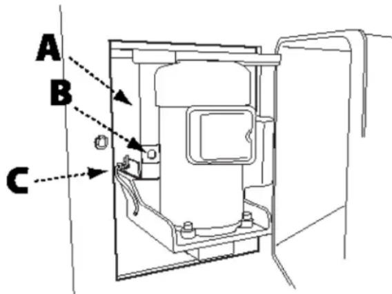
FIGURE 13
ACCESSORIES
A complete line of accessories is available from your DELTA® Supplier, DELTA® Factory Service Centers, and DELTA® Factory Service Centers, and DELTA® Authorized Service Centers. Please visit our Web Site www.DeltaMachinery.com for an online catalog or for the name or your nearest supplier.
Since accessories other than those offered by DELTA ^® have not been tested with this product, use of such accessories could be hazardous. For safest operation, only DELTA ^® recommended accessories should be used with this product.
SERVICE AND REPAIRS
All quality tools will eventually require servicing and/or replacement of parts. For information about DELTA ^® Power Equipment Corporation, its factory-owned branches, or to locate an Authorized Warranty Service Center, visit our website at www.DeltaMachinery.com/service or call our Customer Care Center at 1-800-223-7278. All repairs made by our service centers are fully guaranteed against defective material and workmanship. We cannot guarantee repairs made or attempted by others. By calling this number you can also find answers to most frequently asked questions.
You can also write to us for information at DELTA® Power Equipment Corporation, 2651 New Cut Road, Spartanburg, SC 29303 - Attention: Technical Service Manager. Be sure to include all of the information shown on the nameplate of your tool (model number, type, serial number, date code, etc.)
WARRANTY
To register your tool for warranty service visit our website at www.DeltaMachinery.com.
Five Year Limited New Product Warranty
DELTA® will repair or replace, at its expense and at its option, any new DELTA® machine, machine part, or machine accessory which in normal use has proven to be defective in workmanship or material, provided that the customer returns the product prepaid to a DELTA® factory service center or authorized service station with proof of purchase of the product within five years and provides DELTA® with reasonable opportunity to verify the alleged defect by inspection. For all refurbished DELTA® product, the warranty period is 180 days. DELTA® will not be responsible for any asserted defect which has resulted from normal wear, misuse, abuse or repair or alteration made or specifically authorized by anyone other than an authorized DELTA® service facility or representative. Under no circumstances will DELTA® be liable for incidental or consequential damages resulting from defective products. Some states do not allow the exclusion or limitation of incidental or consequential damages, so the above limitation or exclusion may not apply to you. This warranty is DELTA®'s sole warranty and sets forth the customer's exclusive remedy, with respect to defective products; all other warranties, express or implied, whether of merchantability, fitness for purpose, or otherwise, are expressly disclaimed by DELTA®. For further detail of warranty coverage and warranty repair information, visit www.DeltaMachinery.com or call 1-800-223-7278. This warranty gives you specific legal rights and you may have other rights which vary in certain states or provinces.
LATIN AMERICA: This warranty does not apply to products sold in Latin America. For products sold in Latin America, see country specific warranty information contained in the packaging, call the local company or see website for warranty information.

POWER EQUIPMENT CORPORATION
PARTS, SERVICE OR WARRANTY ASSISTANCE
All DELTA® machines and accessories are manufactured to high quality standards and are serviced by a network of DELTA® Factory Service Centers and DELTA® Authorized Service Centers. To obtain additional information regarding your DELTA® quality product or to obtain parts, service, warranty assistance, or the location of the nearest service center, please call 1-800-223-7278.
REPLACEMENT PARTS
Use only identical replacement parts. For a parts list or to order parts, visit our website at www.DeltaMachinery.com/service. You can also order parts from your nearest factory-owned branch, Authorized Warranty Service Center or by calling Technical Service Manager at 1-800-223-7278 to receive personalized support from one of our highly-trained representatives.
FREE WARNING LABEL REPLACEMENT
If your warning labels become illegible or are missing, call 1-800-223-7278 for a free replacement.
WARNING
For Your Own Safety, Read Instructions Manual Before Operating Sander
- Wear eye protection
- Support work piece with backstop or work table
- Maintain 1/16 inch maximum clearance between table and sanding belt. DPEC00049
SAFETY RULES
DON'T EXPOSE TO RAIN OR USE IN RAIN.
CAREFULLY READ INSTRUCTION MANUAL BEFORE OPERATING MACHINE.
DO NOT OPERATE WITHOUT ALL GUARDS AND COVERS IN POSITION. BE SURE MACHINE IS ELECTRICALLY GROUNDED.
REMOVE OR FASTEN LOOSE ARTICLES OF CLOTHING SUCH AS NECKTIES, ETC. CONFINE HAIR.
REMOVE JEWELRY SUCH AS FINGER RINGS, WATCHES, BRACELETS, ETC.
USE SAFETY FACE SHIELD, GOGGLES, OR GLASSES TO PROTECT EYES AND OTHER PERSONAL SAFETY EQUIPMENT AS REQUIRED.
STOP MACHINE BEFORE MAKING ADJUSTMENTS OR CLEANING CHIPS FROM WORK AREA.
KEEP THE FLOOR AROUND THE MACHINE CLEAN AND FREE FROM SCRAPS, SAWDUST, OIL OR GREASE TO MINIMIZE THE DANGER OF SLIPPING.
DPEC000667
CONSIGNES DE SÉCURITÉ IMPORTANTES
AVERTISSEMENT :
DESCRIPTION FONCTIONNELLE
CARACTÉRISTIQUES DU PRODUIT
| Fréquence d'oscillation 60 courses par minute | |
| Course d'oscillation 38,1 mm (1-1/2 po) | |
| Vitesse de rotation de la broche 1725 TR/MIN | |
| Moteur 1 HP, 110 V, 10 Ampères | |
| Taille de la table 62,5 cm x 62,2 cm (24 – 5/8 po X) | 24 – 1/2 po) |
| Inclinaison de la broche 0° - 45° | |
| Gamme du diamètre de la broche | 6,4 mm (1/4 po), 9,5 mm (3/8 po), 12,7 mm (1/2 po), 15,9 mm (5/8 po), 19,1 mm (3/4 po), 25,4 mm (1 po), 38,1 mm (1-1/2 po), 50,8 mm (2 po), 76,2 mm (3 po), 101,6 mm (4 po) |
| Capteur de poussière 101,6 mm (4 po) | |
| Dimensions de la base 62,9 cm x 50,2 cm (24 – 3/4 po X 19 – 3/4 po) | |
| Poids NET 374 lb |
DÉBALLAGE
⚠ AVERTISSEMENT :
FIGURE 1
FIXER LE VOLANT D'INCLINAISON DE LA BROCHE
Voir Figure 2
FIGURE 3
MONTAGE
INSTALLEZ LES MANCHONS DE PONÇAGE SUR LES BROCHES
Broches en acier de 15,2 cm (6 po)
Voir Figure 4
natural_image
Diagram of a cylindrical object with internal structure and labeled point A (no text or symbols beyond label)FIGURE 5
INSTALLER LA BROCHE SUR LA PONÇEUSE
Voir Figure 6
ATTENTION
FIGURE 6
MONTAGE
SÉLECTIONNER ET INSTALLER L'INSERT DE TABLE
natural_image
Abstract black-and-white circular graphic with concentric arcs and a dot, resembling a stylized CD or DVD icon (no text or symbols)A

natural_image
Black and white icon of a CD or DVD disc with concentric rings (no text or symbols)B

natural_image
Abstract black-and-white circular graphic with concentric arcs (no text or symbols)C

natural_image
Abstract black-and-white circular graphic with concentric arcs and a central hole, no text or symbols present.D

natural_image
Simple black circular shape on white background with partial letter 'E' visible (no text or symbols within the shape)E

natural_image
Simple black circular shape with no text or symbolsFIGURE 7
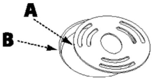
FIGURE 8
MONTAGE
AJUSTER L'ANGLE DE LA TABLE À LA PONCEUSE
FIGURE 9
CONNEXION DU COLLECTEUR DE POUSSIÈRE
FIGURE 11
For Your Own Safety, Read Instructions Manual Before Operating Sander
- Wear eye protection
- Support work piece with backstop or work table
- Maintain 1/16 inch maximum clearance between table and sanding belt. DPEC000493
SAFETY RULES
DON'T EXPOSE TO RAIN OR USE IN RAIN.
CAREFULLY READ INSTRUCTION MANUAL BEFORE OPERATING MACHINE.
DO NOT OPERATE WITHOUT ALL GUARDS AND COVERS IN POSITION. BE SURE MACHINE IS ELECTRICALLY GROUNDED.
REMOVE OR FASTEN LOOSE ARTICLES OF CLOTHING SUCH AS NECKTIES, ETC. CONFINE HAIR.
REMOVE JEWELRY SUCH AS FINGER RINGS, WATCHES, BRACELETS, ETC.
USE SAFETY FACE SHIELD, GOGGLES, OR GLASSES TO PROTECT EYES AND OTHER PERSONAL SAFETY EQUIPMENT AS REQUIRED.
STOP MACHINE BEFORE MAKING ADJUSTMENTS OR CLEANING CHIPS FROM WORK AREA.
KEEP THE FLOOR AROUND THE MACHINE CLEAN AND FREE FROM SCRAPS, SAWDUST, OIL OR GREASE TO MINIMIZE THE DANGER OF SLIPPING.
DPEC000667
SERVICE ET RÉPARATIONS
FIGURA 3
ARMADO
natural_image
Diagram of a cylindrical object with internal structure and labeled point A (no text or symbols beyond label)FIGURA 5
FIGURA 6
natural_image
Abstract black-and-white circular graphic with concentric arcs and a dot (no text or symbols)A

natural_image
Black and white icon of a CD or DVD disc with concentric rings and a central dot (no text or symbols)B

natural_image
Abstract black-and-white circular graphic with concentric arcs (no text or symbols)C

natural_image
Abstract black-and-white circular graphic with concentric curved lines, no text or symbols present.D

natural_image
Simple black circular shape on white background (no text or symbols)E

natural_image
Simple black circular shape with no text or symbolsF
FIGURA 7
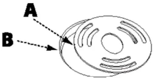
FIGURA 8
ARMADO
FIGURA 9
CONECTAR A UN RECOLECTOR DE POLVO
FIGURA 10
AJUSTES

SERVICIO TÉCNICO Y REPARACIONES
Copyright © 2012 DELTA® Power Equipment Corporation DPEC001142 - 7-18-12
Revised: 02-08-16


- IMPORTANT SAFETY INSTRUCTIONS
- SAFETY GUIDELINES - DEFINITIONS
- GENERAL SAFETY RULES
- ⚠ WARNING: WARNING FAILURE TO FOLLOW THESE RULES MAY RESULT IN SERIOUS PERSONAL INJURY.
- ⚠ WARNING: FAILURE TO FOLLOW THESE RULES MAY RESULT IN SERIOUS INJURY.
- CAUTION:
- WARNING:
- SAVE THESE INSTRUCTIONS.
- POWER CONNECTIONS
- DONGER EXPOSE THE MACHINE TO RAIN OR OPERATE THE MACHINE IN DAMP LOCATIONS.
- MOTOR SPECIFICATIONS
- GROUNDING INSTRUCTIONS
- ▲DANGER: THIS MACHINE MUST BE GROUNDED WHILE IN USE TO PROTECT THE OPERATOR FROM ELECTRIC SHOCK.
- All grounded, cord-connected machines:
- IN ALL CASES, MAKE CERTAIN THE RECEPTACLE IN QUESTION IS PROPERLY GROUNDED. IF YOU ARE NOT SURE, HAVE A QUALIFIED ELECTRICIAN CHECK THE RECEPTACLE.
- EXTENSION CORDS
- A CAUTION: per extension cords.
- KEY FEATURES AND COMPONENTS
- FUNCTIONAL DESCRIPTION
- PRODUCT SPECIFICATIONS
- UNPACKING
- DESCRIPTION (QUANTITY)
- CONTENTS OF HARDWARE PACKAGE
- ASSEMBLY
- ATTACH THE MOTOR COVER
- See Figure 1
- ATTACH THE SPINDLE TILT WHEEL
- See Figure 2
- ATTACH STORAGE HOOKS
- See Figure 3
- INSTALL SANDING SLEEVES ONTO SPINDLES
- 6" Steel Spindles
- See Figure 4
- 9" Steel Spindles
- See Figure 5
- INSTALL THE SPINDLE ONTO THE SANDER
- See Figure 6
- SELECT AND INSTALL THE TABLE INSERT
- CONNECT TO A DUST COLLECTOR
- OPERATION
- See Figure 10.
- ADJUSTMENTS
- ADJUST THE SPINDLE TILT
- ADJUST THE 90° AND 45° POSITIVE STOPS
- RECOMMENDED MAINTENANCE
- ROUTINE INSPECTION
- BEARINGS
- TO CHANGE THE GEAR OIL:
- See Figure 13
- ACCESSORIES
- SERVICE AND REPAIRS
- WARRANTY
- Five Year Limited New Product Warranty
- PARTS, SERVICE OR WARRANTY ASSISTANCE
- REPLACEMENT PARTS
- FREE WARNING LABEL REPLACEMENT
- WARNING
- For Your Own Safety, Read Instructions Manual Before Operating Sander
- SAFETY RULES
- CONSIGNES DE SÉCURITÉ IMPORTANTES
- AVERTISSEMENT :
- DESCRIPTION FONCTIONNELLE
- DÉBALLAGE
- ⚠ AVERTISSEMENT :
- FIXER LE VOLANT D'INCLINAISON DE LA BROCHE
- Voir Figure 2
- MONTAGE
- INSTALLEZ LES MANCHONS DE PONÇAGE SUR LES BROCHES
- Voir Figure 4
- INSTALLER LA BROCHE SUR LA PONÇEUSE
- ATTENTION
- SÉLECTIONNER ET INSTALLER L'INSERT DE TABLE
- AJUSTER L'ANGLE DE LA TABLE À LA PONCEUSE
- CONNEXION DU COLLECTEUR DE POUSSIÈRE
- SERVICE ET RÉPARATIONS
- ARMADO
- CONECTAR A UN RECOLECTOR DE POLVO
- AJUSTES
- SERVICIO TÉCNICO Y REPARACIONES
Brand : DELTA
Model : 31-484
Category : Sander