
31‑482 - Sander DELTA - Free user manual and instructions
Find the device manual for free 31‑482 DELTA in PDF.

| Product Type | Oscillating Spindle Sander |
| Brand | Delta |
| Model | 31-482 |
| Power Supply | 120/240 V, 60 Hz, single-phase |
| Motor | 1 1/2 HP, induction, TEFC |
| Sanding Belt Dimensions | 152.4 mm x 2,260.6 mm |
| Oscillation Stroke | 12.7 mm |
| Oscillations per Minute | 108 |
| Belt Speed | 108 FPM (33 m/min) |
| Table Dimensions (L x W) | 254 mm x 755.7 mm |
| Table Tilt | 0° to 90° |
| Overall Dimensions (L x W x H) | 1295.4 mm x 673.1 mm x 508 mm |
| Net Weight | 98.9 kg |
| Shipping Weight | 105.7 kg |
| Dust Chute Diameter | 101.6 mm |
| Contour Sanding Table Size | 247.7 mm x 298.5 mm |
| Fence (H x L) | 101.6 mm x 609.6 mm |
| Belt Grit Supplied | 100 |
| Warranty | 5-year limited |
| Main Functions | Sanding straight, angled, and contoured surfaces |
| Maintenance and Cleaning | Periodic lubrication of gears, clean belt with appropriate cleaner |
| Safety | Wear safety glasses, unplug before adjustments, keep children away |
Frequently Asked Questions - 31‑482 DELTA
User questions about 31‑482 DELTA
0 question about this device. Answer the ones you know or ask your own.
Ask a new question about this device
Download the instructions for your Sander in PDF format for free! Find your manual 31‑482 - DELTA and take your electronic device back in hand. On this page are published all the documents necessary for the use of your device. 31‑482 by DELTA.
USER MANUAL 31‑482 DELTA
natural_image
Line drawing of a manual milling machine with no text or symbols on the diagram itselfFrançais (16)
Español (30)
www.DeltaMachinery.com
Operating Instructions and Parts Manual
IMPORTANT SAFETY INSTRUCTIONS....2
SAFETY GUIDELINES - DEFINITIONS 3
GENERAL SAFETY RULES 3
POWER CONNECTIONS 5
MOTOR SPECIFICATIONS....5
GROUNDING INSTRUCTIONS ....5
EXTENSION CORDS 6
KEY FEATURES AND COMPONENTS....6
FUNCTIONAL DESCRIPTION 7
PRODUCT SPECIFICATIONS....7
UNPACKING 7
ASSEMBLY 8
Cabinet Assembly 8
Mounting the Table to the Cabinet....8
Sanding Belt 9
Drum Guard 9
Contour Sanding Table....10
Workpiece Support....10
Sanding Fence....11
ADJUSTMENTS....11
Changing the Sanding Angle 11
Re-tensioning the Platen Locking Lever 11
Changing the Sanding Belt 11
Adjusting the Belt Tracking.... 12
Adjusting the Motor Mount Tracking 12
Re-positioning the Table Height....12
MAINTENANCE PROCEDURES 13
Routine Inspection
Lubrication
Cleaning the Sanding Belts
TROUBLESHOOTING 13
ACCESSORIES....14
WARRANTY 14
FRANÇAIS....16
ESPAÑOL 32
IMPORTANT SAFETY INSTRUCTIONS
WARNING: READ AND UNDERSTAND ALL WARNINGS AND OPERATING INSTRUCTIONS BEFORE USING THIS EQUIPMENT. Failure to follow all instructions listed below, may result in electric shock, fire, and/or serious personal injury or property damage.

Woodworking can be dangerous if safe and proper operating procedures are not followed. As with all machinery, there are certain hazards involved with the operation of the product. Using the machine with respect and caution will considerably lessen the possibility of personal injury. However, if normal safety precautions are overlooked or ignored, personal injury to the operator may result. Safety equipment such as guards, push sticks, hold-downs, featherboards, goggles, dust masks and hearing protection can reduce your potential for injury. But even the best guard won't make up for poor judgment, carelessness or inattention. Always use common sense and exercise caution in the workshop. If a procedure feels dangerous, don't try it. Figure out an alternative procedure that feels safer. REMEMBER: Your personal safety is your responsibility. For additional information please visit our website www.DeltaMachinery.com.
⚠ WARNING: This machine was designed for certain applications only. DELTA® strongly recommends that this machine not be modified and/or used for any application other than that for which it was designed. If you have any questions relative to a particular application, DO NOT use the machine until you have first contacted DELTA® to determine if it can or should be performed on the product.
If you have any questions relative to its application DO NOT use the product until you have written DELTA® and we have advised you. Contact us online at www.DeltaMachinery.com or by mail at Technical Service Manager, Delta Power Equipment Corporation, 2651 New Cut Road, Spartanburg, South Carolina 29303.
Information regarding the safe and proper operation of this tool is available from the following sources:
• Power Tool Institute, 1300 Sumner Avenue, Cleveland, OH 44115-2851 or online at www.powertoolinstitute.com
• National Safety Council, 1121 Spring Lake Drive, Itasca, IL 60143-3201
- American National Standards Institute, 25 West 43rd Street, 4 floor, New York, NY 10036 www.ansi.org - ANSI 01.1 Safety Requirements for Woodworking Machines
• U.S. Department of Labor regulations www.osha.gov
SAFETY GUIDELINES - DEFINITIONS
This manual contains information that is important for you to know and understand. This information relates to protecting YOUR SAFETY and PREVENTING EQUIPMENT PROBLEMS. To help you recognize this information, we use the symbols below. Please read the manual and pay attention to these sections.
DANGER:
Indicates an imminently hazardous situation which, if not avoided, will result in death or serious injury.
WARNING:
Indicates a potentially hazardous situation which, if not avoided, could result in death or serious injury.
CAUTION:
Indicates a potentially hazardous situation which, if not avoided, may result in minor or moderate injury.
CAUTION
Used without the safety alert symbol indicates potentially hazardous situation which, if not avoided, may result in property damage.
| Some of the following symbols may be used on the tool. Please study them and learn their meaning. Proper interpretation on these symbols will allow you to operate the tool better and safer. SYMBOL NAME DESIGNATION/EXPLANATION | ||
| [A670] | Safety Alert Indicates a p | potential personal injury hazard. |
 | Read Operator's Manual | To reduce the risk of injury, userMUSTread and understand operator's manual before using this product. |
| [OKY2] | Eye Protection | ALWAYSwear eye protection with side shields marked to comply with ANSI Z87.1. |
 | No Hands Symbol | Failure toKEEPyour hands away from the belt will result in serious personal injury. |
 | Wet Conditions Alert DO | NOTexpose to rain or use in damp locations. |
| [YTZA] | Pinch Warning | ALWAYSwatch for movement paying extra attention to potential areas where pinching could occur. |
| V Volts Voltage | ||
| A Amperes Current | ||
| Hz | Hertz | Frequency (cycles per second) |
| min | Minutes | Time |
| ~/AC | Alternating Current | Type of current |
| no | No Load Speed | Rotational speed, at no load |
| .../min Per | Minute Revolutions, strokes, surface speed, orbits, etc., per minute | |
| Lbs | Pounds | Unit of weight |
| Kg | Kilograms | Unit of weight |
| RPM | Revolutions Per Minute | Speed of rotation of machine |
| PH:1 | Phase 1 | This is a 1 phase motor |
GENERAL SAFETY RULES
WARNING:
WARNING FAILURE TO FOLLOW THESE RULES MAY RESULT IN SERIOUS PERSONAL INJURY.
FOR YOUR OWN SAFETY, READ AND UNDERSTAND THE INSTRUCTION MANUAL BEFORE OPERATING THE UNIT. Learn the unit's application and limitations as well as the specific hazards peculiar to it.
- KEEP WORK AREA CLEAN. Cluttered areas and benches invite accidents.
- DON'T USE IN DANGEROUS ENVIRONMENT. Don't use this unit in damp or wet locations, or expose it to rain. Keep work area well-lighted.
- KEEP CHILDREN AND VISITORS AWAY. All children and visitors should be kept a safe distance from work area.
• DISCONNECT UNIT before servicing.
- CHECK DAMAGED PARTS. Before further use of the unit, properly repair or replace any part that is damaged.
WARNING:
FAILURE TO FOLLOW THESE RULES MAY RESULT IN SERIOUS INJURY.
- Read and understand the warnings posted on the machine and in this manual. Failure to comply with all of these warnings may cause serious injury.
-
Replace the warning labels if they become obscured or removed.
-
This Oscillating Edge Sander is designed and intended for use by properly trained and experienced personnel only. If you are not familiar with the proper and safe operation of an edge sander, do not use until proper training and knowledge have been obtained.
GENERAL SAFETY RULES
- Do not use this machine for other than its intended use. If used for other purposes, Delta Power Equipment Corporation disclaims any real or implied warranty and holds itself harmless from any injury that may result from that use.
- Always wear approved safety glasses/face shields while using this Oscillating Edge Sander.
- Before operating this edge sander, remove tie, rings, watches and other jewelry, and roll sleeves up past the elbows. Remove all loose clothing and confine long hair. Non-slip footwear or anti-skid floor strips are recommended. Do not wear gloves.
- Wear ear protectors (plugs or muffs) during extended periods of operation.
-
Some dust created by power sanding, sawing, grinding, drilling and other construction activities contain chemicals known to cause cancer, birth defects or other reproductive harm. Some examples of these chemicals are:
-
Lead from lead based paint.
- Crystalline silica from bricks, cement and other masonry products.
- Arsenic and chromium from chemically treated lumber.
Your risk of exposure varies, depending on how often you do this type of work. To reduce your exposure to these chemicals, work in a well-ventilated area and work with approved safety equipment, such as face or dust masks that are specifically designed to filter out microscopic particles.
- Do not operate this machine while tired or under the influence of drugs, alcohol or any medication.
- Make certain the switch is in the OFF position before connecting the machine to the power source.
- Make certain the machine is properly grounded.
- Make all machine adjustments or maintenance with the machine unplugged from the power source.
- Form a habit of checking to see that all extra equipment such as adjusting keys, wrenches, scrap, stock, and cleaning rags are removed away from the machine before turning on.
- Keep safety guards in place at all times when the machine is in use. If removed for maintenance purposes, use extreme caution and replace the guards immediately when maintenance is complete.
-
Make sure the edge sander is firmly secured to the floor before use.
-
Check damaged parts. Before further use of the machine, a guard or other part that is damaged should be carefully checked to determine that it will operate properly and perform its intended function. Check for alignment of moving parts, binding of moving parts, breakage of parts, mounting and any other conditions that may affect its operation. A guard or other part that is damaged should be properly repaired or replaced.
- Provide for adequate space surrounding work area and non-glare, overhead lighting.
- Keep the floor around the machine clean and free of scrap material, oil and grease.
- Keep visitors a safe distance from the work area. Keep children away.
- Make your workshop child proof with padlocks, master switches or by removing starter keys.
- Give your work undivided attention. Looking around, carrying on a conversation and “horse-play” are careless acts that can result in serious injury.
- Maintain a balanced stance at all times so that you do not fall or lean against the sanding belt or other moving parts. Do not overreach or use excessive force to perform any machine operation.
- Use the right tool at the correct speed and feed rate. Do not force a tool or attachment to do a job for which it was not designed. The right tool will do the job better and safer.
- Use recommended accessories; improper accessories may be hazardous.
- Maintain machinery with care. Follow instructions for lubricating and changing accessories.
- Turn off the machine before cleaning. Use a brush or compressed air to remove dust or debris — do not use your hands.
- Do not stand on the machine. Serious injury could occur if the machine tips over.
- Never leave the machine running unattended. Turn the power off and do not leave the machine until it comes to a complete stop.
- At all times hold the stock firmly.
- Do not use this sander for other than it intended use. If used for other purposes, Delta Power Equipment Company Inc., disclaims any real or implied warranty and holds itself harmless for any injury or damage which may result from that use.
PROPOSITION 65 WARNING:
WARNING:
Some dust created by power sanding, sawing, grinding, drilling, and other construction activities contains chemicals known to the state of California to cause cancer, birth defects or other reproductive harm. Some examples of these chemicals are:
- Lead from lead-based paints
• Crystalline silica from bricks and cement and other masonry products
• Arsenic and chromium from chemically-treated lumber
Your risk from these exposures varies, depending on how often you do this type of work. To reduce your exposure to these chemicals: work in a well-ventilated area and work with approved safety equipment, such as dust masks that are specifically designed to filter out microscopic particles.
SAVE THESE INSTRUCTIONS.
Refer to them often and use them to instruct others.
POWER CONNECTIONS
POWER CONNECTIONS
A separate electrical circuit should be used for your machines. This circuit should not be less than #12 wire and should be protected with a 20 Amp time lag fuse. If an extension cord is used, use only 3-wire extension cords which have 3-prong grounding type plugs and matching receptacle which will accept the machine's plug. Before connecting the machine to the power line, make sure the switch(s) is in the "OFF" position and be sure that the electric current is of the same characteristics as indicated on the machine. All line connections should make good contact. Running on low voltage will damage the machine.
ADNIGER: OSE THE MACHINE TO RAIN OR OPERATE THE MACHINE IN DAMP LOCATIONS.
MOTOR SPECIFICATIONS
Your machine is wired for 120/240 volts, 60 HZ alternating current. Before connecting the machine to the power source, make sure the switch is in the "OFF" position.
GROUNDING INSTRUCTIONS
▲ DANGER: THIS MACHINE MUST BE GROUNDED WHILE IN USE TO PROTECT THE OPERATOR FROM ELECTRIC SHOCK.
1. All grounded, cord-connected machines:
In the event of a malfunction or breakdown, grounding provides a path of least resistance for electric current to reduce the risk of electric shock. This machine is equipped with an electric cord having an equipment-grounding conductor and a grounding plug. The plug must be plugged into a matching outlet that is properly installed and grounded in accordance with all local codes and ordinances.
Do not modify the plug provided - if it will not fit the outlet, have the proper outlet installed by a qualified electrician.
Improper connection of the equipment-grounding conductor can result in risk of electric shock. The conductor with insulation having an outer surface that is green with or without yellow stripes is the equipment-grounding conductor. If repair or replacement of the electric cord or plug is necessary, do not connect the grounding conductor to a live terminal.
Check with a qualified electrician or service personnel if the grounding instructions are not completely understood, or if in doubt as to whether the machine is properly grounded.
Use only 3-wire extension cords that have 3-prong grounding type plugs and matching 3-conductor receptacles that accept the machine's plug, as shown in Figure A.
Repair or replace damaged or worn cord immediately.
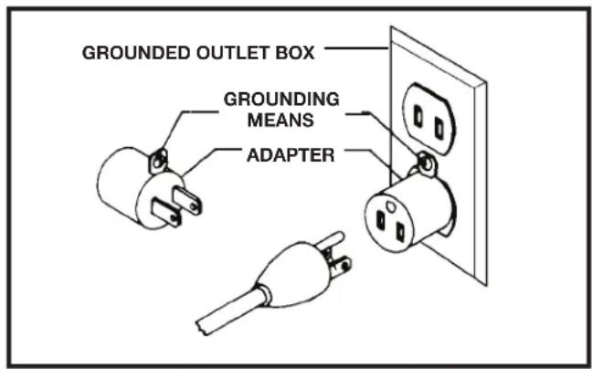
2. Grounded, cord-connected machines intended for use on a supply circuit having a nominal rating less than 150 volts:
If the machine is intended for use on a circuit that has an outlet that looks like the one illustrated in Figure A, the machine will have a grounding plug that looks like the plug illustrated in Figure A. A temporary adapter, which looks like the adapter illustrated in Figure B, may be used to connect this plug to a matching 2-conductor receptacle as shown in Figure B if a properly grounded outlet is not available. The temporary adapter should be used only until a properly grounded outlet can be installed by a qualified electrician. The green-colored rigid ear, lug, and the like, extending from the adapter must be connected to a permanent ground such as a properly grounded outlet box. Whenever the adapter is used, it must be held in place with a metal screw.
NOTE: In Canada, the use of a temporary adapter is not permitted by the Canadian Electric Code.
A DANGERES, MAKE CERTAIN THE RECEPTACLE IN QUESTION IS PROPERLY GROUNDED. IF YOU ARE NOT SURE, HAVE A QUALIFIED ELECTRICIAN CHECK THE RECEPTACLE.
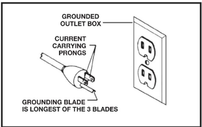
FIGURE A FIGURE B
POWER CONNECTIONS
3. 120 Volt Single-Phase Operation
The motor supplied with your machine is a dual voltage, 120/230 volt motor. It is shipped ready-to-run for 230 volt operation. However, it can be converted for 120 volt operation.
A qualified electrician should do the conversion, or the machine can be taken to an Authorized Delta Service Center. When completed, the machine must conform to the National Electric Code and all local codes and ordinances.
The machine is converted by re-wiring the motor for 120 volts, installing a 120 volt plug on the power supply cord and replacing the switch with one that is rated for 120 volt operation. Be sure the 120 volt plug is only used in an outlet having the same configuration as the plug illustrated in Figure A. or B. No adapter should be used with the 230 volt plug.
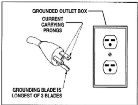
FIGURE C
EXTENSION CORDS
△CAUTION: Use proper extension cords. Make sure your extension cord is in good condition and is a 3-wire extension cord which has a 3-prong grounding type plug and matching receptacle which will accept the machine's plug. When using an extension cord, be sure to use one heavy enough to carry the current of the machine. An undersized cord will cause a drop in line voltage, resulting in loss of power and overheating. Figure D shows the correct gauge to use depending on the cord length. If in doubt, use the next heavier gauge. The smaller the gauge number, the heavier the cord.
⚠ WARNING: In all cases, make certain that the receptacle in question is properly grounded. If you are not sure, have a qualified electrician check the receptacle.
| MINIMUM GAUGE EXTENSION CORDRECOMMENDED SIZES FOR USE WITH STATIONARY ELECTRIC MACHINES | |||
| Ampere Rating | Volts T | total Length of Cord in Feet | Gauge of Extension Cord |
| 0-6 | 120 | up to 25 | 18 AWG |
| 0-6 | 120 | 25-50 | 16 AWG |
| 0-6 | 120 | 50-100 | 16 AWG |
| 0-6 | 120 | 100-150 | 14 AWG |
| 6-10 | 120 | up to 25 | 18 AWG |
| 6-10 | 120 | 25-50 | 16 AWG |
| 6-10 | 120 | 50-100 | 14 AWG |
| 6-10 | 120 | 100-150 | 12 AWG |
| 10-12 | 120 | up to 25 | 16 AWG |
| 10-12 | 120 | 25-50 | 16 AWG |
| 10-12 | 120 | 50-100 | 14 AWG |
| 10-12 | 120 | 100-150 | 12 AWG |
| 12-16 | 120 | up to 25 | 14 AWG |
| 12-16 | 120 | 25-50 | 12 AWG |
| 12-16 | 120 | ||
| GREATER THAN 50 FEET NOT RECOMMENDED | |||
FIGURE D
KEY FEATURES AND COMPONENTS
1-Dust Collection Port
2-Sanding Belt
3-Cabinet
4-Power Switch
5-Platen Lock
6-Support Fence
7-Belt Tensioning Lever
8-Contour Sanding Table
9-1 1/2HP Induction Motor
10-Workpiece Support
11-Rear Belt Guard
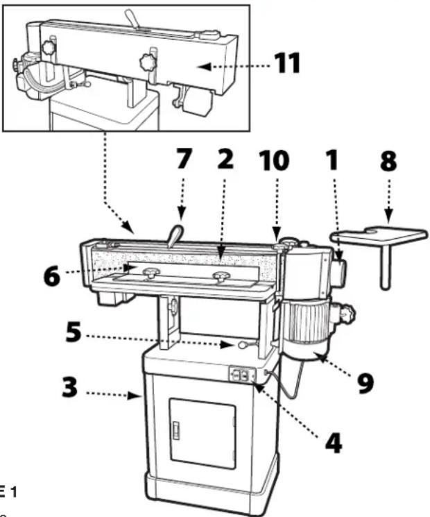
FIGURE 1
FUNCTIONAL DESCRIPTION
The DELTA ^® Oscillating Edge Sander is a professional-grade tool designed for both straight and angled edge-face sanding as well as contour sanding. It is capable of sanding in either the vertical or horizontal plane. Your DELTA ^® Oscillating Edge Sander comes with a 100 grit sanding belt and is mounted on a cabinet base that provides ample storage space for accessories. This tool is powered by a 1 1/2HP, 120/240V induction motor that drives the sanding belt and provides an oscillation stroke of 1/2 inch at a rate of 108 strokes per minute.
PRODUCT SPECIFICATIONS
| Model 31-482 | |
| Fence (HxL) 4 inches x 24 inches | |
| Abrasive Belt Size (WxL) 6 inches x 89 inches | |
| Dust Chute Diameter 4 inches | |
| Contour Sanding Table Size 9 3/4 inches x 11 3/4 inches | |
| Table Size (LxW) 10 inches x 29 3/4 inches | |
| Table Tilt 0-90° | |
| Motor 1 1/2HP, 120/240V, 1PH, 60Hz, TEFC | |
| Sanding Belt Speed 3900 FPM | |
| Oscillation Stroke | 1/2 inches |
| Oscillations per Minute | 108 |
| Overall Dimensions (LxWxH) | 51 inches x 26.5 inches x 20 inches |
| Net Weight, approximate | 218 lbs |
| Shipping Weight, approximate | 233 lbs |
TOOLS NEEDED FOR ASSEMBLY
- Two 12mm wrenches or sockets
- 10mm wrench or socket
- Flat head screw driver
• Phillips head screw driver - Rubber mallet
UNPACKING
Your Oscillating Edge Sander comes packed in a single container. Open the shipping container and check that all parts are present and in good condition:
DESCRIPTION (QUANTITY)
| Front Cabinet Panel with Door (1) | Owner's Manual (1) |
| Rear Cabinet Panel (1) | Warranty Card (1) |
| Side Cabinet Panels (2) | Table Assembly (1) |
| Cabinet Shelf (1) | Back Stop Bracket (1) |
| Rubber Feet (4) | Belt Tension Handle (1) |
| Lock Knob - 35mm (1) | Belt Tracking Tool (1) |
| Lock Knob - 20mm (1) | Miter Gauge Assembly (1) |
| Lock Knob - 12mm (2) | Sanding Belt (1) |
| Contour Sanding Table (1) | Mounting Bracket (1) |
| Drum Guard/Dust Port (1) |
Compare the contents of your container with the parts list to make sure all parts are present and intact. Report any missing or damaged parts to your distributor. Prior to tool assembly and use, read this manual thoroughly to familiarize yourself with proper assembly, maintenance and safety procedures.
HARDWARE
| 5/16 inch x 5/8 inch Screws (4) |
| 5/16 inch Flat Washers (22) |
| 5/16 inch Hex Nuts (12) |
| 5/16 inch x 5/8 inch Hex Cap Bolts (8) |
| 5/16 inch x 1 1/4 inch Hex Cap Bolts (2) |
| 5/16 inch Flat Washers (4) |
| 5/16 inch Lock Washers (10) |
| M5x10 Pan Head Screws (2) |
| M5 Flat Washers (2) |
| M5 Lock Washers (2) |
| 1/4 inch x 5/8 inch Hex Cap Bolts (5) |
| 1/4 inch Flat Washers (5) |
| 1/4 inch Lock Washers (5) |
| 10 24 x 3/4 Socket Head Cap Screws (2) |
| Pan Head Screws (3) |
| T-Nuts (2) |
CABINET ASSEMBLY
TOOLS REQUIRED
- 12mm wrench
• Phillips head screw driver
PARTS
- Rubber Feet (4)
- Side Cabinet Panels (2)
- Front Cabinet Panel with Door (1)
- Rear Cabinet Panel (1)
- Cabinet Shelf (1)
Before beginning assembly, clean all rust protected surfaces with a mild solvent. Do not use paint or lacquer thinner, gasoline, or mineral spirits; as these will damage painted surfaces.
NOTE: To ensure the top cabinet surface, where you will mount the tool, is level and flush, assemble the cabinet upside down on a flat surface.
- Referring to Figure 2, attach the four rubber pads (A) to the bottoms of the side panels (B) with four each 5/16 inch x 5/8 inch screws, 5/16 inch flat washers and 5/16 inch hex nuts.
- Use four 5/16 inch x 5/8 inch hex cap screws, eight 5/16 inch flat washers, four 5/16 inch lock washers, and four 5/16 inch hex nuts to attach the side panels (B) to the front panel (C). Hand tighten only.
- Attach the rear cabinet panel (D) to the side panels using four 5/16 inch x 5/8 inch hex cap screws, eight 5/16 inch flat washers, four 5/16 inch lock washers, and four 5/16 inch hex nuts.
- Turn cabinet right side up on a level surface and ensure the top edges of all panels are flush.
- Install the cabinet shelf (E) to the inside of the cabinet using two M5x10 pan head screws, two M5 flat washers and two M5 lock washers.
- Tighten all hardware.
HARDWARE NEEDED
- 5/16 inch x 5/8 inch screws (4)
- 5/16 inch flat washers (20)
- 5/16 inch hex nuts (12)
- 5/16 inch x 5/8 inch hex cap bolts (8)
- 5/16 inch lock washers (8)
• M5x10 pan head screws (2)
• M5 flat washers (2)
• M5 lock washers (2)
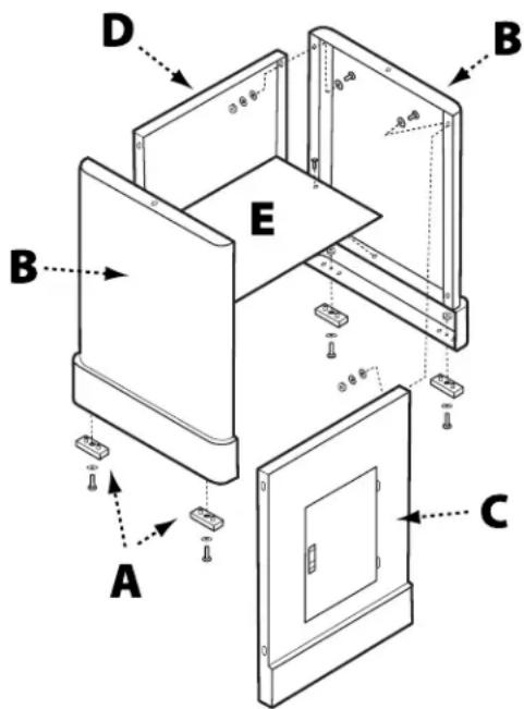
FIGURE 2
MOUNTING THE TABLE ASSEMBLY TO THE CABINET
TOOLS REQUIRED
- 12mm wrench
PARTS
- Table Assembly
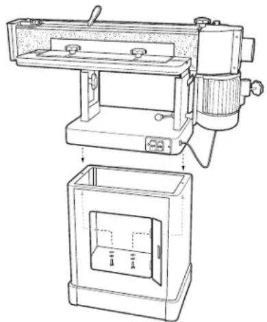
WARNING: This step requires two adults. The table assembly is heavy, be careful when lifting it onto the stand! Failure to comply may cause serious injury and/or damage to the sander and/or property!
- With the aid of another person, carefully lift the table assembly onto the cabinet and position it so that the two holes in the base of the table assembly align with the holes located on either end of the cabinet. See Figure 3.
- Open the cabinet door and, from inside the cabinet, feed a 5/16 inch x 1 1/4 inch hex cap screw up through both holes and secure using a 5/16 inch lock washer and 5/16 inch flat washer. See Figure 5.
- Tighten hardware using a 12mm socket wrench.
HARDWARE NEEDED
- 5/16 inch x 1 1/4 inch hex cap screws (2)
- 5/16 inch lock washers (2) 5/16 inch flat washers (2)
natural_image
Technical line drawing of a mechanical device with a close-up view of its internal components (no text or symbols)FIGURE 3
INSTALLING THE SANDING BELT
TOOLS REQUIRED
- Rubber Mallet
PARTS
- 6 inch x 89 inch sanding belt
-
Belt tensioning lever handle
-
From the rear of the machine, unlock the sanding platen assembly by pulling the lock handle (A) toward you as indicated in Figure 4. Rotate the sanding platen assembly to the vertical position.
- Push the lock handle back to its original position to lock the platen assembly in place.
NOTE: Do not turn or rotate the lock handle as this will change the tension of the locking assembly and make it necessary for adjustment before using the tool.
- Remove the belt guard by loosening the two lock knobs (B) and sliding the belt guard to the right.
- Place the handle (D) onto the belt tensioning lever and gently tap into place using a rubber mallet.
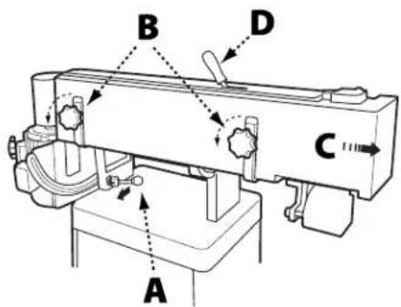
FIGURE 4
HARDWARE NEEDED
- None
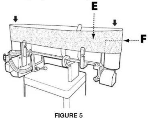
- Move the lever in the direction indicated on the label to release tension on the belt.
- Fit the belt onto the sanding platen so that the edge of the belt (E) is even with the edge of the rollers (F) as shown in Figure 5.
NOTE: Make sure that direction arrow on belt matches the direction indicator on the top of the sanding platen.
- Return the belt tensioning lever to the Tight position. Rotate the belt by hand in the direction indicated by the arrow to ensure proper belt tracking. If the belt tracking needs adjustment, see Belt Tracking Adjustment on page 12.
INSTALLING DRUM GUARD
TOOLS REQUIRED
• Phillips head screw driver
- Flat head screw driver
- Attach one side of the hinge assembly (A) to the rear belt guard using four Phillips head screws.
- Place the drum guard (B) over the dust chute (C) as shown in Figure 6.
- Secure the other side of the hinge to the drum guard with the four remaining Phillips head screws.
- Make sure the drum guard is in the closed position, covering the drive belt.
NOTE: If the drum guard does not clear the motor case, loosen the two lock knobs on the rear belt guard and raise the rear belt guard slightly then retighten the lock knobs.
- Assemble one 12mm flat washer on each of the two 12mm lock knobs (D) and insert one lock knob through the slot in the connection plate and the other through the hole in the connection plate.
- Tighten both knobs until secure.
To reposition the drum guard, loosen both lock knobs, open or close the cover, then retighten the lock knobs.
PARTS
- Hinge
- Drum Guard
• 12mm Lock Knobs (2)
HARDWARE NEEDED
• 8 Phillips head screws
- 12mm flat washers (2)
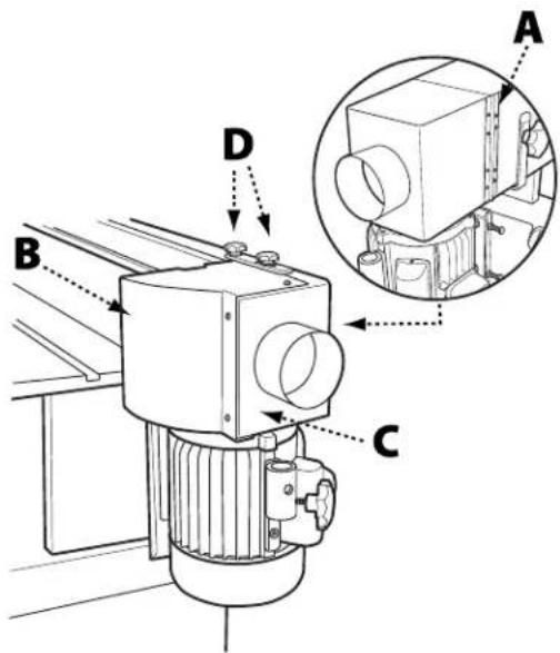
FIGURE 6
INSTALLING THE CONTOUR SANDING TABLE
TOOLS REQUIRED
- 12mm socket wrench
PARTS
- Contour Sanding Table
- Mounting Pole
- Mounting Bracket
- 20mm Lock Knob
HARDWARE NEEDED
• 10 24 x 3/4 Socket Head Cap Screws (2)
- 12mm Hex Cap Bolt
- Loosen the lock knobs (A) on the drum guard (B) and rotate the drum guard back and out of the way. Retighten the lock knobs.
- Attach the mounting bracket (C) to the side of the motor housing and secure using the two 10 24 x 3/4 socket head cap screws, as shown in Figure 7. The longer end of the mounted bracket should be at the bottom.
- Insert the mounting pole (D) into the contour sanding table (E) and secure with 12mm hex cap bolt and lock nut.
- Insert the mounting pole/table assembly into the mounting bracket. Ensure there is clearance on all sides between the sanding belt and the contour sanding table.
- Secure the mounting pole/table assembly to the mounting bracket using the (20mm) lock knob (F).
Important: When the contour sanding table is not in use, the drum guard/dust port should always be in the closed position so the drive drum is not in view.
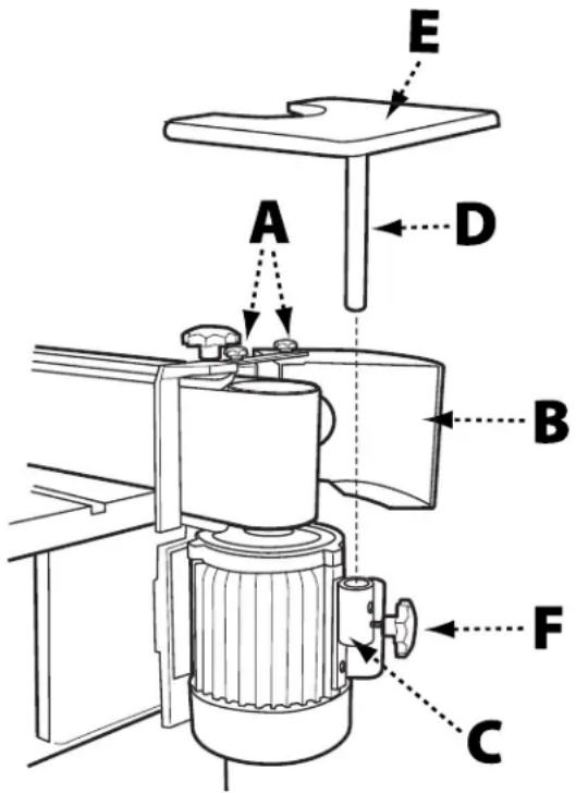
FIGURE 7
INSTALLING THE WORKPIECE SUPPORT
TOOLS REQUIRED
- None
PARTS
- Workpiece Support
• (35mm) Lock Knob
HARDWARE NEEDED
- None
- Locate the two holes (A) on the right hand side of the top of the sanding platen. See Figure 8.
- Insert the pin of the workpiece support (C) into the hole closest to the front.
- Secure the workpiece support to the sanding platen by screwing the (35mm) lock knob (D) into the tapped hole closest to the rear.
- Ensure the workpiece support is as close to the sanding belt (B) as possible without touching it.
- Tighten the lock knob.
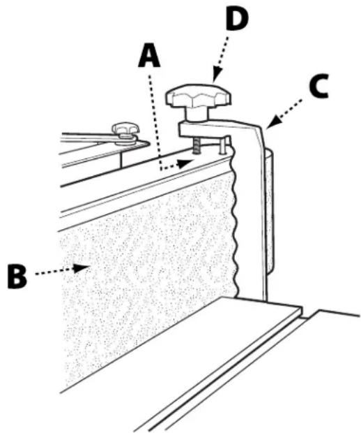
FIGURE 8
INSTALLING THE SANDING FENCE
TOOLS REQUIRED
- None
PARTS
- Sanding Fence
- Two (12mm) Lock Knobs
HARDWARE NEEDED
• T-Nuts (2)
• 5/16 inch Flat Washers (2)
- Slide the two T-nuts into the slot located on the sanding table.
- Position the sanding fence so that one of the t-nuts is aligned with one of the positioning slots.
-
Place a 5/16 inch flat washer onto a (12mm) lock knob and thread the lock knob into the t-nut.
-
Reposition the sanding fence so that the other positioning slot is aligned with second t-nut.
- Place a 5/16 inch flat washer onto the second (12mm) lock knob and thread the lock knob into the second t-nuts.
- Position the fence to the desired distance from the belt and securely tighten both lock knobs.
ADJUSTMENTS
⚠ WARNING: Before making any adjustments to the tool, disconnect the machine from the power source.
TO ADJUST THE SANDING ANGLE
⚠ WARNING: Before making any adjustments to the tool, disconnect the machine from the power source.
- Loosen the platen locking lever by pulling forward.
-
Move the sanding platen to the desired position. Use a combination square between the table and sanding platen to get precise angles.
-
Hold the platen steady and push the platen locking lever back to the locked position.
TO ADJUST THE TENSION ON THE PLATEN LOCKING LEVER
⚠ WARNING: Before making any adjustments to the tool, disconnect the machine from the power source.
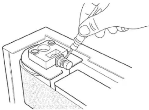
- Loosen the platen locking lever (A) and rotate the platen into the horizontal (flat) position. Do not lock.
- Adjust tension on the eccentric block by tightening the nylon nut (B) with a 14mm wrench. See Figure 9. Turn the nut in 1/4-turn increments and test locking handle for proper tension.
- The platen locking lever is properly tensioned when it requires positive force to move the eccentric block from one side to the other.
- Ensure the platen and motor assembly remains stationary when the platen locking lever is in the locked position. Re-adjust as necessary.
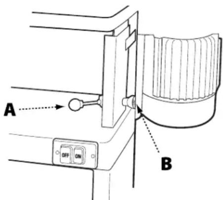
FIGURE 9
TO CHANGE THE SANDING BELT
⚠ WARNING: Before making any adjustments to the tool, disconnect the machine from the power source.
- Ensure the sanding platen is locked in the vertical (upright) position. Reposition if needed. (Refer to Adjusting the Sanding Angle at the top pf this page).
- Remove the belt guard by loosening the two lock knobs and sliding the belt guard to the right.
- Release tension on the belt by moving the belt tensioning lever to the Loose position as indicated on the label on top of the guard.
- Remove the old belt by working it up and over the rollers.
- Fit the new belt onto the sanding platen. Note: Make sure that direction arrow on belt matches the direction indicator on the top of the sanding platen. The edge of the belt should be even with the edge of the rollers.
- Re-tension the belt by moving the belt tensioning lever to the Tight position.
- Rotate the belt by hand in the direction indicated by the arrow to ensure proper belt tracking. Note: Belts stretch with wear. When replacing a belt, you may have to adjust tracking. See Belt Tracking Adjustment on page 12.
- Reinstall the belt guard and tighten the lock handles.
ADJUSTMENTS
TO ADJUST THE BELT TRACKING
WARNING:
Tools Needed: Belt Tracking Tool (provided)
Before making any adjustments to the tool, disconnect the machine from the power source.
- Rotate the belt by hand from left to right and observe whether the belt is tracking above or below the edges of the rollers.
- Using the belt tracking tool (provided) loosen the micro adjust lock nut.
-
Based on whether the belt is tracking up or down, turn the micro adjusting screw in 1/4 – turn increments to the left or right until the belt tracks evenly on the rollers when rotated by hand. See Figure 10.
-
Re-tighten the micro adjusting nut.
NOTE: The Belt Tracking Adjustment provides a minor adjustment that should correct most tracking problems. If the tracking problem persists, use the Motor Mount
Tracking
Adjustment (next section).
natural_image
Line drawing of a hand using a screwdriver to adjust or install a mechanical component (no text or symbols present)FIGURE 10
MOTOR MOUNT TRACKING ADJUSTMENT
Tools Needed: Two 1/2 inch Wrenches
Note: The Motor Mount Tracking Adjustment is a course adjustment. Use the Belt Tracking Adjustment first for fine adjustment. If it cannot be adjusted, then use the procedure described below.
WARNING:
Before making any adjustments to the machine from the power source.
- Loosen the four motor mount nuts (A) just enough so the tracking screws can be turned to make an adjustment. See Figure 11.
- Loosen the two locking hex nuts that secure the tracking screws.
-
Turn one screw a 1/4-turn and rotate the sanding belt by hand to observe which direction the adjustment is causing the belt to move. If it is traveling in the direction needed to correct the problem, go to step 5.
-
If the belt tracks in the wrong direction, back off a 1/4-turn and tighten the other screw a quarter turn. This should start the belt moving in the proper direction.
-
Tighten both locking nuts and motor mount nuts.
-
Return to the Belt Tracking Adjustment section (previous page) to fine tune the tracking.
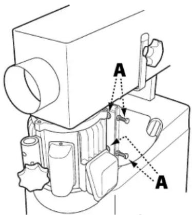
FIGURE 11
TO ADJUST THE SANDING TABLE HEIGHT
WARNING:
Before making any adjustments to the machine from the power source.
tool, disconnect
WARNING:
Never position the sanding table below
the sanding belt! Keep an overlap of at least 1/16 inch between table and sanding belt to avoid material and/or fingers getting caught! Failure to comply may cause serious injury!
- There are two height elevation lock knobs (A) one on either side of the table support, shown in Figure 12. Loosen both lock knobs just enough to allow the sanding table to move up and down.
WARNING:
The table is very heavy. Loosen lock
knobs slowly and just enough to create play in table. Failure to comply may cause serious injury!
-
Raise or lower work table to desired level.
-
Tighten the lock knobs.
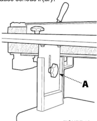
FIGURE 12
MAINTENANCE PROCEDURES
Your Oscillating Edge Sander requires little maintenance beyond the routine inspection, lubrication, and cleaning.
ROUTINE INSPECTION
It is a good idea to routinely inspect any quality woodworking tool in order to keep it in optimum condition. This includes inspecting all hardware for tightness, ensuring drive belts are in good condition, and cleaning debris and grime from any surfaces and moving parts.
LUBRICATION
The sealed motor of your Oscillating Edge Sander is maintenance-free. However, it is recommended that you periodically lubricate the gears in the gear box using a quality #2 grease or equivalent. To keep the sander table and other bare metal parts in good working condition, apply an occasional coat of quality paste wax, free of silicone or synthetics.
CLEANING THE SANDING BELT
Regularly inspect and, if necessary, clean the sanding belt with a high quality gum rubber belt cleaner. If you notice sanding performance is significantly decreasing, it may be time to replace the sanding belt. Refer to directions on page 11.
TROUBLESHOOTING GUIDE
| TROUBLE POSSIBLE CAUSE | SOLUTION | |
| Sander will not start | 1. Sander unplugged from wall or motor2. Fuse blown or circuit breaker tripped3. Cord damaged | 1. Check all plug connections2. Replace fuse or reset circuit breaker3. Replace cord |
| Sanding belt does not come up to speed | 1. Extension cord too light or too long2. Motor not wired for proper voltage3. Low current | 1. Replace with adequate size and length cord (see Recommended Extension Cord Gauges on page 6)2. Refer to motor junction cover for proper wiring3. Contact a qualified electrician |
| Machine vibrates excessively | 1. Stand on uneven floor2. Motor mounts are loose3. Tension spring is worn or broken | 1. Adjust stand so that it rests evenly on the floor2. Tighten motor mount bolts3. Replace spring |
| Abrasive belt keeps tearing | 1. Belt is running in the wrong direction | 1. Arrow on the sanding belt and machine should be pointing in the same direction. |
| Sanded edge not square | 1. Table not square to sanding platen 1. Use a square to adjust table to sanding platen | |
| Sanding marks on wood | 1. Wrong grit sanding belt2. Feed pressure too great3. Sanding against the grain | 1. Use coarser grit for stock removal and fine grit for finish sanding.2. Never force work into sanding platen3. Sand with the grain |
ACCESSORIES
WARNING:
USE ONLY RECOMMENDED ACCESSORIES. Consult the owner's manual for recommended accessories. The
use of improper accessories may cause risk of injury to persons.
A complete line of accessories is available from your DELTA ^® Supplier, DELTA ^® Factory Service Centers, and DELTA ^® Authorized Service Centers. Please visit our Web Site www.DeltaMachinery.com for an online catalog or for the name or your nearest supplier.
WARNING:
Since accessories other than those offered by DELTAhave not been tested with this product, use of such accessories
could be hazardous. For safest operation, ONLY DELTA® recommended accessories should be used with this product.
PARTS, SERVICE OR WARRANTY ASSISTANCE
All DELTA® Machines and accessories are manufactured to high quality standards and are serviced by a network of an Authorized Service Centers. To obtain additional information regarding your product or to obtain parts, service, warranty assistance, or the location of the nearest service center, please call 1-800-223-7278.
Five Year Limited Warranty
- WHAT IS COVERED. Delta Power Equipment Corporation ("Company") will, at its option, repair or replace this product, if purchased at retail in the United States or Canada and the product, with normal use, has proven to be defective in workmanship or material, subject to the conditions stated in this Limited Warranty. This Limited Warranty covers only materials and labor. All transportation costs are Customer's responsibility.
- WARRANTY PERIOD. All warranty claims must be submitted within five years from the date of retail purchase. For all service parts and factory refurbished products, the warranty period is 180 days.
- HOW TO OBTAIN SERVICE. To obtain warranty service, you must return the defective product, at your expense, to a service center authorized by Company to perform warranty service (a "Company Authorized Service Center") within the applicable warranty period, together with acceptable proof of purchase, such as your original receipt bearing the date of purchase, or product registration number. Company reserves the right to restrict warranty claim service to the country where the purchase was made and/or to charge for the cost to export service parts or provide warranty service in a different country. For this purpose, on-line purchases are deemed made in the United States. For the location of your nearest Company Authorized Service Center, call Company's Customer Care Center at (800) 223-7278.
4. EXCLUSIONS:
- Company does not offer any warranty on products purchased in used or damaged condition.
- Company does not warrant any products purchased outside the United States or Canada
- Company will not be responsible for any damage that has resulted from normal wear, misuse, abuse or any repair or alteration made by anyone other than a Company Authorized Service Center or a designated representative of Company's Customer Care Center.
All IMPLIED WARRANTIES are expressly limited to the warranty period identified above.
Company will not be liable for INCIDENTAL OR CONSEQUENTIAL damages.
This limited warranty is Company's sole warranty and sets forth the customer's exclusive remedy with respect to defective products; all other warranties, express or implied, whether of merchantability, fitness for purpose, or otherwise, are expressly disclaimed by Company, except as expressly stated in this warranty statement.
Some states do not allow the exclusion or limitation of incidental or consequential damages, or the limitation of implied warranties, so the above limitations or exclusions may not apply to you. This warranty gives you specific legal rights and you may have other rights which vary in certain states or provinces. For further details of warranty coverage and warranty repair information, call (800) 223-7278.
LATIN AMERICA: This warranty does not apply to products sold in Latin America. For products sold in Latin America, call the local company or see website for warranty information.
PARTS, SERVICE OR WARRANTY ASSISTANCE
REPLACEMENT PARTS
Use only identical replacement parts. For a parts list or to order parts, visit our website at www.DeltaMachinery.com/service. You can also order parts from your nearest Authorized Warranty Service Center or by calling Technical Service Manager at 1-800-223-7278 to receive personalized support from one of our highly-trained representatives.
FREE WARNING LABEL REPLACEMENT
If your warning labels become illegible or are missing, call 1-800-223-7278 for a free replacement.

WARNING
For Your Own Safety, Read Instructions Manual Before Operating Sander
- Wear eye protection
- Suport work piece with backstop or work table
- Maintain 1/16 inch maximum clearance between table and sanding belt.

SERVICE AND REPAIRS
All quality tools will eventually require servicing and/or replacement of parts. For information about Delta Power Equipment Corporation, its factory-owned branches, or to locate an Authorized Warranty Service Center, visit our website at www.DeltaMachinery.com/service or call Customer Care at 1-800-223-7278. All repairs made by our service centers are fully guaranteed against defective material and workmanship. We cannot guarantee repairs made or attempted by others. By calling this number you can also find answers to most frequently asked questions 24 hours/day. You can also write to us for information at Delta Power Equipment Corporation, 2651 New Cut Road, Spartanburg, SC 29303 - Attention: Technical Service Manager. Be sure to indicate all of the information shown on the nameplate of your saw (model number, type, serial number, date code, etc.).
IMPORTANTES CONSIGNES DE SÉCURITÉ
⚠ AVERTISSEMENT :
ASSUREZ-VOUS D'AVOIR BIEN LU ET COMPRIS TOUTES LES MISES EN GARDE ET LES CONSIGNES D'UTILISATION AVANT D'UTILISER CET

SPÉCIFICATIONS DU PRODUIT
FIGURE 2
MONTAGE DE L'ENSEMBLE DE LA TABLE À L'ARMOIRE
OUTILS REQUIS
- Clé de 12mm
PIÈCES
- Ensemble de la table
⚠ AVERTISSEMENT :
natural_image
Technical line drawing of a machine with internal components and a separate view showing internal compartments (no text or symbols)FIGURE 3
INSTALLATION DE LA COURROIE DE PONÇAGE
OUTILS REQUIS PIÈCES
FIGURE 5
INSTALLATION DU PROTÈGE-TAMBOUR
OUTILS REQUIS PIÈCES
FIGURE 6
INSTALLATION DE LA TABLE DE PONÇAGE POUR CONTOUR
OUTILS REQUIS
natural_image
Line drawing of a hand using a tool to adjust or install a mechanical component (no text or symbols visible)FIGURE 11
natural_image
Technical line drawing of a mechanical assembly with labeled component A (no text or symbols beyond label)FIGURE 12
PROCÉDURES DE MAINTENANCE
TROUBLESHOOTING GUIDE
ASSISTANCE POUR PIÈCES, SERVICE OU GARANTIE
ASSISTANCE POUR PIÈCES, SERVICE OU GARANTIE
PIÈCES DE REMPLACEMENT
For Your Own Safety, Read Instructions Manual Before Operating Sander
- Wear eye protection
- Suport work piece with backstop or work table
- Maintain 1/16 inch maximum clearance between table and sanding belt.

ENTRETIEN ET RÉPARATIONS
FIGURA 2
MONTAJE DEL ENSAMBLE DE MESA EN EL GABINETE
HERRAMIENTAS PIEZAS NECESARIAS • Ensamble
- Llave de tuerca de 12mm
- Ensamble de mesa
natural_image
Technical line drawing of a mechanical device with an inset view showing internal components (no text or symbols)FIGURA 3
FIGURA 5
FIGURA 6
natural_image
Line drawing of a hand using a screwdriver to adjust or install a component, labeled 'FIGURA 10' (no other text or symbols)FIGURA 11
PARA AJUSTAR LA ALTURA DE LA MESA DE LIJADO
ADVERTENCIA:
For Your Own Safety, Read Instructions Manual Before Operating Sander
- Wear eye protection
- Suport work piece with backstop or work table
- Maintain 1/16 inch maximum clearance between table and sanding belt.

MANTENIMIENTO Y REPARACIONES
2651 New Cut Road, Spartanburg, SC 29303
(800) 223-7278
www.DeltaMachinery.com
© 2013 DELTA® Power Equipment Corporation DPEC000265 - 12-10-13
Revised 11-18-2022


- IMPORTANT SAFETY INSTRUCTIONS
- SAFETY GUIDELINES - DEFINITIONS
- DANGER:
- WARNING:
- CAUTION:
- CAUTION
- GENERAL SAFETY RULES
- WARNING FAILURE TO FOLLOW THESE RULES MAY RESULT IN SERIOUS PERSONAL INJURY.
- FAILURE TO FOLLOW THESE RULES MAY RESULT IN SERIOUS INJURY.
- PROPOSITION 65 WARNING:
- SAVE THESE INSTRUCTIONS.
- POWER CONNECTIONS
- ADNIGER: OSE THE MACHINE TO RAIN OR OPERATE THE MACHINE IN DAMP LOCATIONS.
- MOTOR SPECIFICATIONS
- GROUNDING INSTRUCTIONS
- ▲ DANGER: THIS MACHINE MUST BE GROUNDED WHILE IN USE TO PROTECT THE OPERATOR FROM ELECTRIC SHOCK.
- All grounded, cord-connected machines:
- Grounded, cord-connected machines intended for use on a supply circuit having a nominal rating less than 150 volts:
- A DANGERES, MAKE CERTAIN THE RECEPTACLE IN QUESTION IS PROPERLY GROUNDED. IF YOU ARE NOT SURE, HAVE A QUALIFIED ELECTRICIAN CHECK THE RECEPTACLE.
- 120 Volt Single-Phase Operation
- EXTENSION CORDS
- KEY FEATURES AND COMPONENTS
- FUNCTIONAL DESCRIPTION
- PRODUCT SPECIFICATIONS
- TOOLS NEEDED FOR ASSEMBLY
- UNPACKING
- CABINET ASSEMBLY
- TOOLS REQUIRED
- PARTS
- HARDWARE NEEDED
- MOUNTING THE TABLE ASSEMBLY TO THE CABINET
- INSTALLING THE SANDING BELT
- INSTALLING DRUM GUARD
- INSTALLING THE CONTOUR SANDING TABLE
- INSTALLING THE WORKPIECE SUPPORT
- INSTALLING THE SANDING FENCE
- ADJUSTMENTS
- TO ADJUST THE SANDING ANGLE
- TO ADJUST THE TENSION ON THE PLATEN LOCKING LEVER
- TO CHANGE THE SANDING BELT
- TO ADJUST THE BELT TRACKING
- MOTOR MOUNT TRACKING ADJUSTMENT
- TO ADJUST THE SANDING TABLE HEIGHT
- tool, disconnect
- MAINTENANCE PROCEDURES
- ROUTINE INSPECTION
- LUBRICATION
- CLEANING THE SANDING BELT
- ACCESSORIES
- PARTS, SERVICE OR WARRANTY ASSISTANCE
- Five Year Limited Warranty
- EXCLUSIONS:
- REPLACEMENT PARTS
- FREE WARNING LABEL REPLACEMENT
- WARNING
- SERVICE AND REPAIRS
- IMPORTANTES CONSIGNES DE SÉCURITÉ
- ⚠ AVERTISSEMENT :
- ASSUREZ-VOUS D'AVOIR BIEN LU ET COMPRIS TOUTES LES MISES EN GARDE ET LES CONSIGNES D'UTILISATION AVANT D'UTILISER CET
- SPÉCIFICATIONS DU PRODUIT
- MONTAGE DE L'ENSEMBLE DE LA TABLE À L'ARMOIRE
- OUTILS REQUIS
- PIÈCES
- INSTALLATION DE LA COURROIE DE PONÇAGE
- OUTILS REQUIS PIÈCES
- INSTALLATION DU PROTÈGE-TAMBOUR
- INSTALLATION DE LA TABLE DE PONÇAGE POUR CONTOUR
- PROCÉDURES DE MAINTENANCE
- ASSISTANCE POUR PIÈCES, SERVICE OU GARANTIE
- PIÈCES DE REMPLACEMENT
- ENTRETIEN ET RÉPARATIONS
- MONTAJE DEL ENSAMBLE DE MESA EN EL GABINETE
- HERRAMIENTAS PIEZAS NECESARIAS • Ensamble
- PARA AJUSTAR LA ALTURA DE LA MESA DE LIJADO
- ADVERTENCIA:
- MANTENIMIENTO Y REPARACIONES
Brand : DELTA
Model : 31‑482
Category : Sander