
1U24T3PS1HE - Heat pump HAIER - Free user manual and instructions
Find the device manual for free 1U24T3PS1HE HAIER in PDF.

User questions about 1U24T3PS1HE HAIER
0 question about this device. Answer the ones you know or ask your own.
Ask a new question about this device
Download the instructions for your Heat pump in PDF format for free! Find your manual 1U24T3PS1HE - HAIER and take your electronic device back in hand. On this page are published all the documents necessary for the use of your device. 1U24T3PS1HE by HAIER.
USER MANUAL 1U24T3PS1HE HAIER
This manual must be left with the homeowner for future reference.

This is a safety alert symbol and should never be ignored. When you see this symbol on labels or in manuals, be alert to the potential for personal injury or death.
⚠ WARNING
Installation and servicing of air conditioning equipment can be hazardous due to internal refrigerant pressure and live electrical components. Only trained and qualified service personnel should install or service this equipment. Installation and service performed by unqualified persons can result in property damage, personal injury, or death.
WARNING

CTRICAL SHOCK HAZARD!
Risk of electrical shock. Disconnect all remote power supplies before installing or servicing any portion of the system. Failure to disconnect power supplies can result in property damage, personal injury, or death.
WARNING
Sharp metal edges can cause injury.
When installing the unit, use care to avoid sharp edges.
▲IMPORTANT
The Clean Air Act of 1990 bans the intentional venting of refrigerant (CFCs, HCFCs and HFCs) as of July 1, 1992. Approved methods of recovery, recycling or reclaiming must be followed. Fines and/or incarceration may be levied for noncompliance.
TABLE OF CONTENTS
Important Safety Information ....2
Requirements for Operation,
Service and Installation
of Appliances using Flammable
Refrigerants 4
Installation Instructions 9
Maintenance 43
Homeowner Information 44
Limited Warranty 46
Contact Haier at:
Homeowner: Haierappliances.com
or
877.337.3639
Split System USAC and USHP matches:
AHRIDirectory.org
IMPORTANT SAFETY INFORMATION
WARNING
- Installation and servicing of air conditioning equipment can be hazardous due to internal refrigerant pressure and live electrical components. Only trained and qualified service personnel should install or service this equipment. Installation and service performed by unqualified persons can result in property damage, personal injury, or death.
- ELECTRICAL SHOCK HAZARD! Risk of electrical shock. Disconnect all remote power supplies before installing or servicing any portion of the system. Failure to disconnect power supplies can result in property damage, personal injury, or death.
- Sharp metal edges can cause injury. When installing the unit, use care to avoid sharp edges.
-
For your safety, the information in this manual must be followed to minimize the risk of fire, electric shock, or personal injury.
-
Use this equipment only for its intended purpose as described in this manual.
- This heat pump must be properly installed accordance with these instructions before it is used.
- All wiring should be rated for the amperage value listed on the rating plate. Use only copper wiring.
- All electrical work must be completed by a qualified electrician and completed in accordance with local and national building codes.
- Any servicing must be performed by a qualified individual.
- For any service which requires entry into the refrigerant sealed system, Federal regulations require that the work is performed by a technician having a Class II or Universal certification.
- All air conditioners contain refrigerants, which under federal law must be removed prior to product disposal. If you are getting rid of an old product with refrigerants, check with the company handling disposal.
- These R-454B heat pumps systems require that contractors and technicians use tools, equipment and safety standards approved for use with this refrigerant.
- RISK OF ELECTRIC SHOCK. Could cause injury or death.
- An adequate ground is essential before connecting the power supply.
- Disconnect all connected electric power supplies before servicing.
-
Repair or replace immediately all electrical wiring that has become frayed or otherwise damaged. Do not use wiring that shows cracks or abrasion damage along its length or at either end.
-
RISK OF FIRE. Could cause injury or death. Do not store or use combustible materials, gasoline or other flammable vapors or liquids in the vicinity of this or any other appliance.
- This appliance is not intended for use by persons (including children) with reduced physical, sensory or mental capabilities, or lack of experience and knowledge, unless they have been given supervision or instruction concerning use of the appliance by a person responsible for their safety. Children should be supervised to ensure that they do not play with the appliance.
- To avoid danger of suffocation, keep the plastic bag or thin film used as the packaging material away from young in children.
- Be sure not to allow foreign materials (oil, water, etc) entering the refrigerant piping. Seal the ends of refrigerant piping before storage.
- For installation purposes, be sure to use the parts supplied by the manufacturer or other prescribed parts. The use of non-prescribed parts can cause serious accidents such as the unit falling, water leakage, electric shock, or fire.
- The rated power supply of this product is 208/230 VAC/60hz/1PH. Verify the voltage is within 187\~253 range before turning the equipment on.
- Supply power to the heat pump should be from a dedicated circuit that meets branch circuit ampacity requirements.
- Use a special branch circuit breaker and receptacle matched to the power circuit capacity of the heat pump. (Install in accordance with local technical standard for electrical equipment).
- Perform wiring work in accordance with standards so that the air conditioner can be operated safely and positively.
- If the SUPPLY CORD is damaged, it must be replaced by the manufacturer, its service agent or similarly qualified persons in order to avoid a hazard.
READ AND SAVE THESE INSTRUCTIONS
IMPORTANT SAFETY INFORMATION
CAUTION
- Aluminum electrical wiring may present special problems - consult a qualified electrician.
- When the unit is in the STOP position, there is still voltage to the electrical controls.
▲IMPORTANT
- The Clean Air Act of 1990 bans the intentional venting of refrigerant (CFCs, HCFCs and HFCs) as of July 1, 1992. Approved methods of recovery, recycling or reclaiming must be followed. Fines and/or incarceration may be levied for noncompliance.
REQUIREMENTS FOR OPERATION, SERVICE AND INSTALLATION OF APPLIANCES USING FLAMMABLE REFRIGERANTS
A2L
WARNING
Flammable Materials, Refrigerant class per ISO 817
- Do not use means to accelerate the defrosting process or to clean, other than those recommended by the manufacturer.
-
The appliance shall be stored in a room without continuously operating ignition sources (for example: open flames, an operating gas appliance or an operating electric heater.
-
Do not pierce or burn.
- Be aware that refrigerants may not contain an odor.
General
- During installation, due to the extended refrigerant pipes, additional REFRIGERANT may be charged. Refer to the nameplate attached to the unit for details.
- Handling, installation, cleaning, servicing and disposal of refrigerant must comply with the local regulation and the instruction.
– Servicing shall be performed only as recommended by the manufacturer. -
Spaces where refrigerant pipes are allowed shall comply with the below requirement:
-
that piping material, pipe routing, and installation shall include protection from physical damage in operation and service, and be in compliance with national and local codes and standards, such as ASHRAE 15, IAPMO Uniform Mechanical Code, ICC International Mechanical Code, or CSA B52. All field joints shall be accessible for inspection prior to being covered or enclosed.
- that the installation of pipe-work shall be kept to a minimum.
- that the mechanical connections between parts created during installation are accessible for maintenance purposes.
- that protection devices, piping, and fittings shall be protected as far as possible against adverse environmental effects, for example, the danger of water collecting and freezing in relief pipes or the accumulation of dirt and debris.
- that piping in refrigeration systems shall be so designed and installed to minimize the likelihood of hydraulic shock damaging the system.
-
that precautions shall be taken to avoid excessive vibration or pulsation.
-
that after completion of field piping for split systems, the field pipework shall be pressure tested with an inert gas and then vacuum tested prior to refrigerant charging, according to the following requirements:
- The minimum test pressure for the low side of the system shall be the low side design pressure and the minimum test pressure for the high side of the system shall be the high side design pressure, unless the high side of the system, cannot be isolated from the low side of the system in which case the entire system shall be pressure tested to the low side design pressure.
- The test pressure after removal of pressure source shall be maintained for at least 1 hour with no decrease of pressure indicated by the test gauge, with test gauge resolution not exceeding 5% of the test pressure.
- During the evacuation test, after achieving a vacuum level specified in the manual or less, the refrigeration system shall be isolated from the vacuum pump and the pressure shall not rise above 1500 microns within 10 min. The vacuum pressure level shall be specified in the manual, and shall be the lessor of 500 microns or the value required for compliance with national and local codes and standards, which may vary between residential, commercial, and industrial buildings.
- that field-made refrigerant joints indoors shall be tightness tested according to the following requirements: The test method shall have a sensitivity of 5 grams per year of refrigerant or better under a pressure of at least 0.25 times the maximum allowable pressure. No leak shall be detected.
REQUIREMENTS FOR OPERATION, SERVICE AND INSTALLATION OF APPLIANCES USING FLAMMABLE REFRIGERANTS
Qualification of Workers
Every working procedure that affects safety shall only be carried out by competent persons.
Examples for such working procedures are:
- breaking into the refrigerating circuit;
- opening of sealed components;
- opening of ventilated enclosures.
The competent persons are trained by the national training organizations or manufacturers that are accredited to teach the relevant national competency standards that may be set in legislation. The achieved competence should be documented by a certificate.
Information on Servicing
Prior to beginning work on systems containing FLAMMABLE REFRIGERANTS, safety checks are necessary to ensure that the risk of ignition is minimized. For repair to the REFRIGERATING SYSTEM, the below requirement shall be completed prior to conducting work on the system:
- Work shall be undertaken under a controlled procedure so as to minimise the risk of a flammable gas or vapor being present while the work is being performed.
- All maintenance staff and others working in the local area shall be instructed on the nature of work being carried out. Work in confined spaces shall be avoided.
- The area shall be checked with an appropriate refrigerant detector prior to and during work, to ensure the technician is aware of potentially toxic or flammable atmospheres. Ensure that the leak detection equipment being used is suitable for use with all applicable refrigerants, i. e. non-sparking, adequately sealed or intrinsically safe.
- If any hot work is to be conducted on the refrigerating equipment or any associated parts, appropriate fire extinguishing equipment shall be available to hand. Have a dry powder or CO2 fire extinguisher adjacent to the charging area.
- No person carrying out work in relation to a REFRIGERATING SYSTEM which involves exposing any pipe work shall use any sources of ignition in such a manner that it may lead to the risk of fire or explosion. All possible ignition sources, including cigarette smoking, should be kept sufficiently far away from the site of installation, repairing, removing and disposal, during which refrigerant can possibly be released to the surrounding space. Prior to work taking place, the area around the equipment is to be surveyed to make sure that there are no flammable hazards or ignition risks. “No Smoking” signs shall be displayed.
-
Ensure that the area is in the open or that it is adequately ventilated before breaking into the system or conducting any hot work. A degree of ventilation shall continue during the period that the work is carried out. The ventilation should safely disperse any released refrigerant and preferably expel it externally into the atmosphere.
-
Where electrical components are being changed, they shall be fit for the purpose and to the correct specification. At all times the manufacturer's maintenance and service guidelines shall be followed. If in doubt, consult the manufacturer's technical department for assistance.
-
The following checks shall be applied to installations using FLAMMABLE REFRIGERANTS:
-
marking to the equipment continues to be visible and legible. Markings and signs that are illegible shall be corrected;
-
refrigerating pipe or components are installed in position where they are unlikely to be exposed to any substance which may corrode refrigerant containing components, unless the components are constructed of materials which are inherently resistant to being corroded or are suitably protected protected against severe corrosion.
-
Repair and maintenance to electrical components shall include initial safety checks and component inspection procedures. If a fault exists that could compromise safety, then no electrical supply shall be connected to the circuit until it is satisfactorily dealt with. If the fault cannot be corrected immediately but it is necessary to continue operation, an adequate temporary solution shall be used. This shall be reported to the owner of the equipment so all parties are advised.
• Initial safety checks shall include: -
that capacitors are discharged: this shall be done in a safe manner to avoid possibility of sparking;
- that no live electrical components and wiring are exposed while charging, recovering or purging the system;
- that there is continuity of grounding.
REQUIREMENTS FOR OPERATION, SERVICE AND INSTALLATION OF APPLIANCES USING FLAMMABLE REFRIGERANTS
Repairs to Sealed Components, Intrinsically Safe Components
- Sealed electrical components shall be replaced.
- Intrinsically safe components must be replaced.
- Replace components only with parts specified by the manufacturer. Other parts may result in the ignition of refrigerant in the atmosphere from a leak.
Cabling
Check that cabling will not be subject to wear, corrosion, excessive pressure, vibration, sharp edges or any other adverse environmental effects. The check shall also take into account the effects of aging or continual vibration from sources such as compressors or fans. Wire routing is designed to keep electrical wiring away from refrigerant containing components. Ensure wire is returned to original routing if any are moved during inspection or repair.
Detection of Flammable Refrigerants
- Under no circumstances shall potential sources of ignition be used in the searching for or detection of refrigerant leaks. A halide torch (or any other detector using a naked flame) shall not be used.
- The following leak detection methods are deemed acceptable for all refrigerant systems:
Electronic leak detectors may be used to detect refrigerant leaks but, in the case of FLAMMABLE REFRIGERANTS, the sensitivity may not be adequate, or may need re-calibration. (Detection equipment shall be calibrated in a refrigerant-free area.) Ensure that the detector is not a potential source of ignition and is suitable for the refrigerant used. Leak detection equipment shall be set at a percentage of the LFL of the refrigerant and shall be calibrated to the refrigerant employed, and the appropriate percentage of gas (25% maximum) is confirmed.
- Leak detection fluids are also suitable for use with most refrigerants but the use of detergents containing chlorine shall be avoided as the chlorine may react with the refrigerant and corrode the copper pipe-work.
NOTE: Examples of leak detection fluids are:
- bubble method,
- fluorescent method agents.
If a leak is suspected, all naked flames shall be removed/extinguished.
If a leakage of refrigerant is found which requires brazing, all of the refrigerant shall be recovered from the system, or isolated (by means of shut off valves) in a part of the system remote from the leak. Removal of refrigerant shall be according to the manual.
Removal and Evacuation
- When breaking into the refrigerant circuit to make repairs – or for any other purpose – conventional procedures shall be used. However, for flammable refrigerants it is important that best practice be followed, since flammability is a consideration. The following procedure shall be adhered to:
- safely remove refrigerant following local and national regulations;
- purge the circuit with inert gas;
-
open the circuit by cutting or brazing.
-
The refrigerant charge shall be recovered into the correct recovery cylinders if venting is not allowed by local and national codes. For appliances containing flammable refrigerants, the system shall be purged with oxygen-free nitrogen to render the appliance safe for flammable refrigerants. This process might need to be repeated several times.
- Compressed air or oxygen shall not be used for purging refrigerant systems.
- The outlet for the vacuum pump shall not be close to any potential ignition sources, and ventilation shall be available.
REQUIREMENTS FOR OPERATION, SERVICE AND INSTALLATION OF APPLIANCES USING FLAMMABLE REFRIGERANTS
Charging Procedures
- In addition to conventional charging procedures, the following requirements shall be followed.
- Ensure that contamination of different refrigerants does not occur when using charging equipment. Hoses or lines shall be as short as possible to minimise the amount of refrigerant contained in them.
- Cylinders shall be kept in an appropriate position according to the instructions.
-
Ensure that the REFRIGERATING SYSTEM is grounded prior to charging the system with refrigerant.
-
Label the system when charging is complete (if not already).
- Extreme care shall be taken not to overfill the REFRIGERATING SYSTEM.
- Prior to recharging the system, it shall be pressure-tested with the appropriate purging gas. The system shall be leak-tested on completion of charging but prior to commissioning. A follow up leak test shall be carried out prior to leaving the site.
Decommissioning
- Before carrying out this procedure, it is essential that the technician is completely familiar with the equipment and all its detail. It is recommended good practice that all refrigerants are recovered safely. Prior to the task being carried out, an oil and refrigerant sample shall be taken in case analysis is required prior to re-use of recovered refrigerant. It is essential that electrical power is available before the task is commenced.
- Become familiar with the equipment and its operation.
- solate system electrically.
-
Before attempting the procedure, ensure that:
-
mechanical handling equipment is available, if required, for handling refrigerant cylinders;
- all personal protective equipment is available and being used correctly;
- the recovery process is supervised at all times by a competent person;
-
recovery equipment and cylinders conform to the appropriate standards.
-
Pump down refrigerant system, if possible.
- If a vacuum is not possible, make a manifold so that refrigerant can be removed from various parts of the system.
- Make sure that cylinder is situated on the scales before recovery takes place.
- Start the recovery machine and operate in accordance with instructions.
- Do not overfill cylinders (no more than 80% volume liquid charge).
- Do not exceed the maximum working pressure of the cylinder, even temporarily.
- When the cylinders have been filled correctly and the process completed, make sure that the cylinders and the equipment are removed from site promptly and all isolation valves on the equipment are closed off.
- Recovered refrigerant shall not be charged into another REFRIGERATING SYSTEM unless it has been cleaned and checked.
Labeling
Equipment shall be labeled stating that it has been de-commissioned and emptied of refrigerant. The label shall be dated and signed. For appliances containing FLAMMABLE REFRIGERANTS, ensure that there are labels on the equipment stating the equipment contains FLAMMABLE REFRIGERANT.
REQUIREMENTS FOR OPERATION, SERVICE AND INSTALLATION OF APPLIANCES USING FLAMMABLE REFRIGERANTS
Recovery
- When removing refrigerant from a system, either for servicing or decommissioning, it is recommended good practice that all refrigerants are removed safely.
- When transferring refrigerant into cylinders, ensure that only appropriate refrigerant recovery cylinders are employed. Ensure that the correct number of cylinders for holding the total system charge is available. All cylinders to be used are designated for the recovered refrigerant and labelled for that refrigerant (i. e. special cylinders for the recovery of refrigerant). Cylinders shall be complete with pressure-relief valve and associated shut-off valves in good working order. Empty recovery cylinders are evacuated and, if possible, cooled before recovery occurs.
-
The recovery equipment shall be in good working order with a set of instructions concerning the equipment that is at hand and shall be suitable for the recovery of all appropriate refrigerants including, when applicable, FLAMMABLE REFRIGERANTS. In addition, a set of calibrated weighing scales shall be available and in good working order. Hoses shall be complete with leak-free disconnect couplings and in good condition. Before using the recovery machine, check that it is in satisfactory working order, has been properly maintained and that any associated electrical components are sealed to prevent ignition in the event of a refrigerant release. Consult manufacturer if in doubt.
-
The recovered refrigerant shall be returned to the refrigerant supplier in the correct recovery cylinder, and the relevant waste transfer note arranged. Do not mix refrigerants in recovery units and especially not in cylinders.
- If compressors or compressor oils are to be removed, ensure that they have been evacuated to an acceptable level to make certain that FLAMMABLE REFRIGERANT does not remain within the lubricant. The evacuation process shall be carried out prior to returning the compressor to the suppliers. Only electric heating to the compressor body shall be employed to accelerate this process. When oil is drained from a system, it shall be carried out safely.
INSTALLATION INSTRUCTIONS
Application
These units are designed for use in residential and light commercial type buildings. Units should be installed with approved indoor matches listed in the Air-Conditioning, Heating and Refrigeration Institute (AHRI) Directory of Certified Products. Refer to AHRIDirectory.org.
These units comply with UL 60335-2-40/CSA C22.2 No. 60335-2-40, or UL 1995/CSA C22.2 No 236. and must be connected to other units that also are compliant.
The majority of states codes have adopted UL60335-2-40 Edition 4. A limited number of local and state codes may require compliance to UL 60335-2-40 Edition 3. Please refer to our website at
GEAppliancesairandwater.com
for guidance on installations in those localities.
1) These units are PARTIAL UNIT AIR CONDITIONERS, complying with PARTIAL UNIT requirements of this Standard, and must only be connected to other units that have been confirmed as complying to corresponding PARTIAL UNIT requirements of this Standard, UL60335-2-40/CSA C22.2 No. 60335-2-40, or UL 1995/CSA C22.2 No 236.
2) Warning: Assure that PARTIAL UNITS shall only be connected to an appliance suitable for the same refrigerant.
3) Assure the maximum operating pressure is considered when connecting to any indoor units.
4) According to ASHRAE 15, these units can stop compressor working in 10s when receiving the signal from the Refrigerant detection systems in indoor units. Please verify and assure the validity during installation.
NOTE – R-454b is a A2L refrigerant. The system installation must meet the following parameters based upon total refrigerant charge (line set included). TAmin (Total minimum conditioned area) is the minimum allowable conditioned area based upon the total system charge at sea level. Values must be multiplied by altitude adjustment factor at installed altitude.
Qmin table refers to minimum airflow requirements during refrigerant leak mitigation by the refrigerant detection system, based upon total system charge.
See tables on this page.
| TAmin Table | |||||||||||||||
| Charge (Ibs) 4 4.5 5 5.5 6 | 6.5 7 7.5 | 8 8.5 9 | 9.5 10 | 10.5 11 | |||||||||||
| Charge (kg) | 1.8 | 2.0 | 2.2 | 2.5 | 2.7 | 2.9 | 3.1 | 3.4 | 3.6 | 3.8 | 4.0 | 4.3 | 4.5 | 4.7 | 5.0 |
| Minimum Conditioned Area (ft ^2 ) | 59 | 67 | 74 | 82 | 89 | 97 | 104 | 112 | 119 | 127 | 134 | 142 | 149 | 157 | 164 |
| Minimum Conditioned Area (m ^2 ) | 5.4 | 6.2 | 6.8 | 7.6 | 8.2 | 9.0 | 9.6 | 10.4 | 11.0 | 11.7 | 12.4 | 13.1 | 13.8 | 14.5 | 15.2 |
NOTE – Table is based on the configuration where the discharge port and air return port in the room is higher than 2.2m. NOTE – Multiply values in TAmin table by the Altitude Adjustment Factors to correct TAmin based on installed altitude.
| Altitude Adjustment Factor | |||||||||
| Altitude (m) | 0 | 200 | 400 | 600 | 800 | 1000 | 1200 | 1400 | 1600 |
| Altitude (ft) | 0 | 660 | 1310 | 1970 | 2620 | 3280 | 3940 | 4590 | 5250 |
| Adj. Factor | 1 | 1 | 1 | 1 | 1.02 | 1.05 | 1.04 | 1.1 | 1.12 |
| Altitude (m) | 1600 | 1800 | 2000 | 2200 | 2400 | 2600 | 2800 | 3000 | 3200 |
| Altitude (ft) | 5250 | 5910 | 6560 | 7220 | 7870 | 8530 | 9190 | 9840 | 10500 |
| Adj. Factor | 1.12 | 1.15 | 1.18 | 1.21 | 1.25 | 1.28 | 1.32 | 1.36 | 1.4 |
| Qmin Table | |||
| Refrigerant Charge lb (kg) | CFM Required | Refrigerant Charge lb (kg) | CFM Required |
| 5 (2.268) | 135 | 18 (8.165) | 487 |
| 6 (2.722) | 162 | 19 (8.618) | 514 |
| 7 (3.175) | 189 | 20 (9.072) | 541 |
| 8 (3.629) | 216 | 21 (9.525) | 568 |
| 9 (4.082) | 244 | 22 (9.979) | 595 |
| 10 (4.536) | 271 | 23 (10.433) | 622 |
| 11 (4.990) | 298 | 24 (10.886) | 649 |
| 12 (5.443) | 325 | 25 (11.340) | 676 |
| 13 (5.897) | 352 | 26 (11.793) | 704 |
| 14 (6.350) | 379 | 27 (12.247) | 731 |
| 15 (6.804) | 406 | 28 (12.701) | 758 |
| 16 (7.257) | 433 | 29 (13.154) | 785 |
| 17 (7.711) | 460 | 30 (13.608) | 812 |
NOTE – Qmin minimum airflow requirement for refrigerant leak mitigation.
INSTALLATION INSTRUCTIONS
General
Read this entire instruction manual, as well as the instructions supplied in separate equipment, before starting the installation. Observe and follow all warnings, cautions, instructional labels, and tags. Failure to comply with these instructions could result in an unsafe condition and/or premature component failure.
These instructions are intended as a general guide only for use by qualified personnel and do not supersede any national or local codes in any way. The installation must comply with all provincial, state, and local codes as well as the National Electrical Code (U.S.) or Canadian Electrical Code (Canada). Compliance should be determined prior to installation.
This unit uses R-454B, which is an ozone-friendly HFC refrigerant. The unit must be installed with a matching indoor coil and line set. A filter drier approved for use with R-454B is installed in the unit.
IMPORTANT: This product has been designed and manufactured to meet ENERGY STAR criteria for energy efficiency when matched with appropriate coil components. However, proper refrigerant charge and proper air flow are critical to achieve rated capacity and efficiency. Installation of this product should follow the manufacturer's refrigerant charging and air flow instructions. Failure to confirm proper charge and airflow may reduce energy efficiency and shorten equipment life.
Inspection of Shipment
Upon receipt of equipment, carefully inspect it for possible shipping damage. If damage is found, it should be noted on the carrier's freight bill. Take special care to examine the unit inside the carton if the carton is damaged. Any concealed damage discovered should be reported to the last carrier immediately, preferably in writing, and should include a request for inspection by the carrier's agent.
If any damages are discovered and reported to the carrier DO NOT INSTALL THE UNIT, as claim may be denied.
Check the unit rating plate to confirm specifications are as ordered.
Safety Precautions
Follow all safety codes. Wear safety glasses and work gloves. Use quenching cloth for brazing operations. Have fire extinguisher available. Read these instructions thoroughly and follow all warning or cautions attached to the unit.
- Always wear proper personal protection equipment.
- Always disconnect electrical power before removing panel or servicing equipment.
- Keep hands and clothing away from moving parts.
- Handle refrigerant with caution; refer to proper MSDS from refrigerant supplier.
- Use care when lifting, avoid contact with sharp edges.
INSTALLATION INSTRUCTIONS
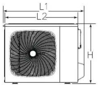
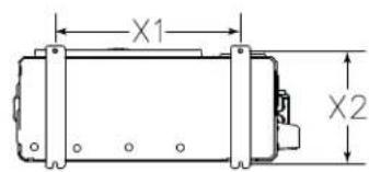
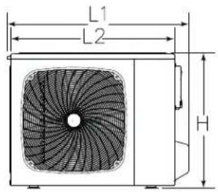
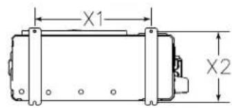
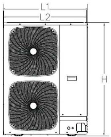
Unit Dimensions (Inches)
| Model 24K 36K 60k | |||
| L1 40-3/16 43-1/8 | 41-5/8 | ||
| L2 36-1/4 41-3/8 4 | 1-5/8 | ||
| D2 14-5/8 15-3/4 | 5-3/4 | ||
| D1 17-1/8 19-7/8 | 9-7/8 | ||
| H 30-1/8 33-1/16 | 56-5/16 | ||
| X1 26 26-9/16 26-9/16 | |||
| X2 15-13/16 18-1/8 | 8 18-1/8 | ||
| Weight (Ship) - lbs (kg) 176.4 | (80) 213.8 | (97) 306.4 | (139) |
| Weight (Net) - lbs (kg) | 134.5(61) | 167.5(76) | 257.9(117) |
24K Units
text_image
L1 L2 H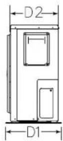
text_image
X1 X236K Units
text_image
L1 L2 H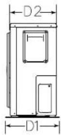
text_image
X1 X260K Units
text_image
L1 L2 H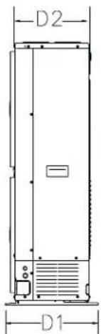
text_image
D2 D1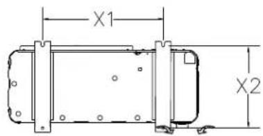
text_image
X1 X2INSTALLATION INSTRUCTIONS
INSTALLATION
WARNING
To prevent personal injury, as well
as damage to panels, unit or structure, observe the following:
While installing or servicing this unit, carefully stow all removed panels so that the panels will not cause injury to personnel, objects or nearby structures. Also, take care to store panels where they will not be subject to damage (e.g., being bent or scratched).
While handling or stowing the panels, consider any weather conditions (especially wind) that may cause panels to be blown around and damaged.
NOTE: In some cases, noise in the living area has been traced to gas pulsations from improper installation of equipment.
- Locate unit away from windows, patios, decks, etc. where unit operation sounds may disturb customer.
- Leave some slack between structure and unit to absorb vibration.
- Place a sound-absorbing material, such as Isomode, under the unit if it will be installed in a location or position that will transmit sound or vibration to the living area or adjacent buildings.
- Install the unit high enough above the ground or roof to allow adequate drainage of defrost water and prevent ice buildup.
- In heavy snow areas, do not locate the unit where drifting snow will occur. The unit base should be elevated above the depth of average snows.
NOTE: Elevation of the unit may be accomplished by constructing a frame using suitable materials. If a support frame is constructed, it must not block drain holes in unit base.
- When installed in areas where low ambient temperatures exist, locate unit so winter prevailing winds do not blow directly into outdoor coil.
- Locate unit away from overhanging roof lines which would allow water or ice to drop on, or in front of, coil or into unit.
DO LOCATE THE UNIT:
- With proper clearances on sides and top of unit
- On a solid, level foundation or pad (unit must be level to within ± 1/4 in./ft. per compressor manufacturer specifications)
• To minimize refrigerant line lengths
DO NOT LOCATE THE UNIT:
- On brick, concrete blocks or unstable surfaces
• Near clothes dryer exhaust vents
• Near sleeping area or near windows - Under eaves where water, snow or ice can fall directly on the unit
- Installation clearance to be 4 inches from the rear and 14 inches from the front.
Operating Ambient
The minimum outdoor operating ambient in cooling mode is 5^ F, and the maximum outdoor operating ambient in cooling mode is 125^ F. The maximum outdoor operating ambient in heating mode is 75^ F.
Rooftop Installations
Install unit at a minimum of 6" above surface of the roof to avoid ice buildup around the unit. Locate the unit above a load bearing wall or area of the roof that can adequately support the unit. Consult local codes for rooftop applications.
If unit cannot be mounted away from prevailing winds, a wind barrier should be constructed. Due to variation in installation applications, size and locate barrier according to the best judgment of the installer.
OPERATING RANGE
The following information lists the operating range specific:
• Cooling: 5°F - 125°F
- Heating: -22^ - 75^
NOTES:
- When the outdoor temperature drops below -22^ (-30°C), the unit will stop running. The unit will turn back on automatically when the temperature rises above the lowest limit and the pressure returns to the closing pressure of the low-pressure switch.
- It is recommended to have a secondary heating source(s) available in case the temperature drops below the operating range.
CAUTION
- It is highly recommended that you do not open or close the stop valves when the outdoor temperature is below -5^ (-21°C) as this may cause refrigerant leakage.
- Make sure power is turned on for at least 12 hours after periods of being powered down in an 32^ (0^) environment or lower.
- Do not touch the fins of the coil. Touching the coil fins could result in damage to the fins or personal injury such as skin rupture.
- Ensure the power circuit capacity is adequate for all loads connected to the electrical service panel. Increase the conductor and panel capacity if the total electrical loads exceed the power source capacity.
- Contact the power utility if the power provided is below equipment rating plate requirements.
- Be sure to install a breaker of the specified capacity.
-
Regulation of cables and breaker differs from each locality, refer in accordance with local rules.
-
Use refrigerant tubing that is clean and free of any contamination which may cause damage to the system including sulfur, copper oxide, dust, metal chips, powder, oil or water.
- Avoid brazing lines together. Use a continuous length of copper tubing as oxides formed during improper brazing techniques can damage the equipment.
- Do not use copper pipes that have a collapsed, deformed, or discolored portion (especially on the interior surface). Otherwise, the expansion valve or capillary tube may become blocked with contaminants.
- Improper line sizing will degrade performance. Peak pressure of R454B is much higher than R22. Use copper tubing with adequate wall thickness.
- To prevent breaking of the pipe, avoid sharp bends. Bend the pipe with a radius of curvature of 4 in. (100 mm) or more.
- If the pipe is bent repeatedly at the same place, it will break.
REQUIRED TOOLS FOR INSTALLATION
• 14/4 AWG stranded wire
- 5/8"(16mm), 7/8"(22mm), 1"(25mm) or adjustable wrench
- R-454B refrigerant*
- Adhesive tape
- Conduit cable clamp 1/2
- Copper line set (for size, see Table on page 17)
- # 2 phillips screwdriver
- Drill
- Flaring tool
- Hex wrench
- Hole saw 21/4"
- Insulation*
- Refrigerant scale
- Level
- Manifold gauge set
- Measuring tape
- Micron gauge
- Nitrogen*
- Pipe cutter
- PVC pipe (optional)
- Razor knife
-
Reamer
-
Saddle clamp (L.S.) w/ screws
- Sealant, non-expanding (for lineset hole)
- Soap/water solution* or gas leakage detector
- Stud finder
- Torque wrench
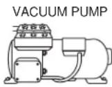
- Vacuum pump
- Wire strippers
- All usual and customary HVAC hand and power tools, meters, and testing devices
* consumable
INSTALLATION INSTRUCTIONS
INCLUDED ACCESSORIES
| Outdoor Unit Included Accessories | ||
| Name Appearance Quantity | ||
| Rubber Damping Pad |  | 4 |
| Suction Extension Pipe | 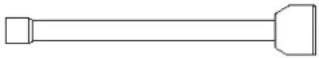 | 1 |
| Liquid Extension Pipe | 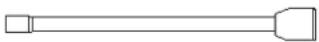 | 1 |
| Installation Manual |  | 1 |
▲IMPORTANT
Exhaust vents from dryers,
water heaters and furnaces should be directed away from the outdoor unit. Prolonged exposure to exhaust gases and the chemicals contained within them may cause condensation to form on the steel cabinet and other metal components of the outdoor unit. This will diminish unit performance and longevity.
When outdoor unit is connected to factory-approved indoor unit, outdoor unit contains system refrigerant charge for operation with matching indoor unit when connected by 15 ft. of field-supplied tubing. For proper unit operation, check refrigerant charge using charging information located on control box cover.
Operating in 4-Ton Mode
Refer to Table 7 on page 36 for the correct switch settings to configure the unit from 5-Ton mode to 4-Ton mode.
Indoor Coil TXV Selection
The outdoor section must be matched to a factory approved indoor section. It is mandatory that the installer ensure that the correct TXV is installed in the indoor section. Reference Refrigerant Piping - Typical Existing Fixed Orifice Removal Procedure. If necessary, remove the existing piston and replace it with the correct TXV. See Refrigerant Piping - Typical Existing Expansion Valve Removal Procedure for details of changing the piston or TXV. The NS18H models are only rated with TXV on the indoor coil.
Outdoor Section
Zoning ordinances may govern the minimum distance the condensing unit can be installed from the property line.
text_image
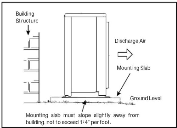
Building Structure Discharge Air Mounting Slab Ground Level Mounting slab must slope slightly away from building, not to exceed 1/4" per foot.Figure 1. Slab Mounting
Install on a Solid, Level Mounting Pad
The outdoor section is to be installed on a solid foundation. This foundation should extend a minimum of 2" (inches) beyond the sides of the outdoor section. To reduce the possibility of noise transmission, the foundation slab should NOT be in contact with or be an integral part of the building foundation. See Figure 1.
If conditions or local codes require the unit be attached to pad or mounting frame, tie down bolts should be used and secured to unit base pan.
Elevate Unit
CAUTION
Accumulation of water and ice in se equipment damage.
Elevate unit per local climate and code requirements to provide clearance above estimated snowfall level and ensure adequate drainage of unit. Use snow stand in areas where prolonged freezing temperatures are encountered.
If conditions or local codes require the unit be attached to pad or mounting frame, tie down bolts should be used and fastened through knockouts provided in unit base pan.
Clearance Requirements
When installing, allow sufficient space for airflow clearance, wiring, refrigerant piping, and service. For proper airflow, quiet operation and maximum efficiency. Position so water, snow, or ice from roof or eaves cannot fall directly on unit. Refer to Table below for installation clearances.
| Location Minimum | Clearance |
| Service box 30" | |
| Discharge Air 14" | |
| Between units 4" | |
| Against wall 4" | |
| * Maximum soffit overhang is 36".NOTE: At least one side should be unobstructed by a wall or other barrier. | |
Table 1. Clearances
Selection of installation location of outdoor
Single-unit installation (unit inch.(mm))
text_image
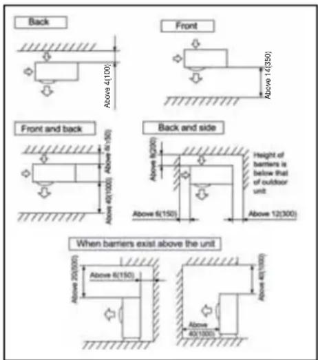
Back Front Front and back Back and side Height of barriers is below that of outdoor unit Above 6(150) Above 12(300) When barriers exist above the unit Above 25(200) Above 6(150) Above 40(100) Above 4(359)Figure 2. Clearance Requirements
The top and two side surfaces must be exposed to open space, and barriers on at least one side of the front and back shall be lower than the outdoor unit.
REFRIGERANT PIPING
- Use only refrigerant grade copper tubes.
- Table 2 shows the pipe installation restrictions for split systems
- Ensure that vapor and liquid tube diameters are appropriate to capacity of unit.
- Run refrigerant tubes as directly as possible by avoiding unnecessary turns and bends.
- When passing refrigerant tubes through the wall, seal opening with RTV or other silicon-based caulk.
- Avoid direct tubing contact with water pipes, duct work, floor joists, wall studs, floors, walls, and any structure.
- Do not suspend refrigerant tubing from joists and studs with a rigid wire or strap that comes in direct contact with tubing.
- Ensure that tubing insulation is pliable and completely surrounds vapor tube.
It is important that no tubing be cut or seals broken until you are ready to actually make connections to the evaporator and to the condenser section. DO NOT remove rubber plugs or copper caps from the tube ends until ready to make connections at evaporator and condenser. Under no circumstances leave the lines open to the atmosphere for any period of time, if so unit requires additional evacuation to remove moisture.
Be extra careful with sharp bends. Tubing can “kink” very easily, and if this occurs, the entire tube length will have to be replaced. Extra care at this time will eliminate future service problems.
It is recommended that vertical suction risers not be up-sized. Proper oil return to the compressor should be maintained with suction gas velocity.
Filter Drier
The factory-installed filter dryer is very important for system reliability. The filter dryer should be replaced before re-charging the unit with refrigerant if the unit needs to have refrigerant evacuated for repair. The specification of the filter dryer can be found in the Table below.
| ODF | Temperature Range | MWP | Compatible Refrigerant |
| 3/8 - 4 | 0°C~+120°C 4.5MPa/650Psig R-454B |
INSTALLATION INSTRUCTIONS
Installation of Line Sets
DO NOT fasten liquid or suction lines in direct contact with the floor or ceiling joist. Use an insulated or suspension type of hanger. Keep both lines separate, and always insulate the suction line. Liquid line runs (30 feet or more) in an attic will require insulation. Route refrigeration line sets to minimize length.
DO NOT let refrigerant lines come in direct contact with foundation. When running refrigerant lines through the foundation or wall, openings should allow for a sound and vibration absorbing material to be placed or installed between tubing and foundation. Any gap between foundation or wall and refrigerant lines should be filled with a vibration damping material.
CAUTION
If ANY refrigerant tubing is required
to be buried by state or local codes, provide a 6 inch vertical rise at service valve.
WARNING
Polyvinyl ether (PVE) oils used with HFC-454B refrigerant absorb moisture very quickly. It is very important that the refrigerant system be kept closed as much as possible. DO NOT remove line set caps or service valve stub caps until you are ready to make connections.
IMPORTANT
If this unit is being matched with an approved line set or indoor unit coil that was previously charged with mineral oil, or if it is being matched with a coil which was manufactured before January of 1999, the coil and line set must be flushed prior to installation. Take care to empty all existing traps. Polyvinyl ether (PVE) and polyol ester (POE) oils are used in these variable-capacity units charged with HFC-454B refrigerant. Residual mineral oil can act as an insulator, preventing proper heat transfer. It can also clog the expansion device and reduce system performance and capacity. Failure to properly flush the system per this instruction and the detailed Installation and Service Procedures manual will void the warranty.
NOTE: "Clean refrigerant" is any refrigerant in a system that has not had compressor burnout. If the system has experienced burnout, it is recommended that the existing line set and indoor coil be replaced.
NOTE: In lieu of R-454B, an industry-standard flushing agent may also be used.
Heat Pump System (HFC454B)
- Total equivalent length equals 180 feet (piping and all fittings included).
• NOTE: Length is general guide. Lengths may be
Flush Line Sets
Flush the existing line set per the following instructions. For more information, refer to the Installation and Service Procedures manual.
CAUTION
Do NOT attempt to flush and re-use existing line sets or indoor coil when the system contains contaminants (i.e., compressor burn out).
Suction Traps
For systems with the outdoor unit 5 - 60 feet above the indoor unit, one trap must be installed at the bottom of the suction riser.
NOTE: Special consideration must be taken for line sets over 50 feet. See Refrigerant Piping Guidelines.
INSTALLATION INSTRUCTIONS
Table 2. Refrigerant Charge and Pipe Length Information
| Model | Refrig. Charge (oz)* | For Liquid Line Length (oz/ft) | Max System Charge (oz) | System Max Pipe Length (ft) | Max Vertical Length (ft) | Service Valve Connection Sizes | Refrigerant Line Sizes | ||
| Suction Line Connection (in) | Liquid Line Connection (in) | Suction Line (in) | Liquid Line (in) | ||||||
| 24k 62 | 0.55 164.25 | 150 50 5/8 | 3/8 | 3/4 | 3/836k 94 | ||||
| 3/4 7/8 | |||||||||
| 60k 12 | 5 0.55 226.25 | 100 50 | |||||||
*Factory charged for 15 feet of line set; adjust per installation instructions.
| Tonnage | Maximum Total Equivalent Length (ft) | Maximum Linear (actual) Length (ft) | Maximum Vapor Riser (ft) | Maximum Linear Liquid Lift (ft) | Preferred Vapor Line Sizes for Horizontal Runs | Required Vapor Riser Size |
| 24K | 180 | 150 | 60 | 60 | 7/8" | 5/8" |
| 36K | 3/4" | |||||
| 60K | 100 | 50 | 50 | 7/8" |
Table 3. Line Set Guidelines – 51 to 150 Linear Feet in Length
| Tonnage | Line Size | Total Linear Length (ft.) | ||||||
| 25 | 50 | 75 | 100 | 125 | 150 | |||
| 24K | 3/8" | 25 | 50 | 50 | 50 | 50 | 50 | Max Elevation (ft) |
| 36K | ||||||||
| 60K | / | / | ||||||
A. Find your tonnage on the left side of the table.
B. Select the actual Total Linear Length of your system shown at the top of the table.
C. The elevation listed in the table is the maximum allowed for the liquid line listed.
Table 4. Liquid Line Diameter Selection
INSTALLATION INSTRUCTIONS
Conventional Line Set Installation: Pipe Bending
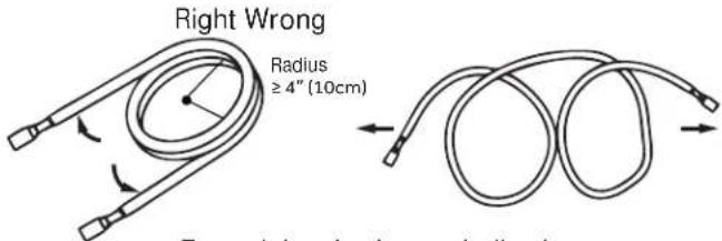
- Use a tubing bender to change pipe direction.
- If tubing is coiled, extend it by unwinding it from one end.
- DO NOT bend the pipe excessively.
text_image
Right Wrong Radius ≥ 4" (10cm) Extracbanched wire windingExtend the pipe by unwinding it
Figure 3. Minimum Bend Radius
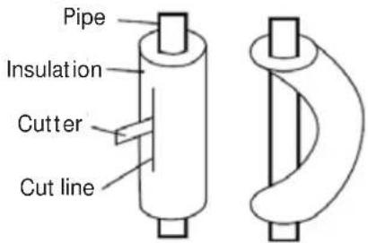
- Use a sharp cutter to cut the pipe insulation as shown, and bend the pipe after it is exposed. After bending, place the insulation back on the pipe and secure it with adhesive tape.
NOTE: Tubing extension is included with the unit.
text_image
Pipe Insulation Cutter Cut lineFigure 4.
Step 1: Cutting
-
When preparing refrigerant pipes, take your time to cut and flare them properly. This will ensure efficient operation and minimize the need for future repairs and loss of comfort.
-
Measure and record the distance between the indoor and outdoor units.
-
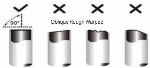
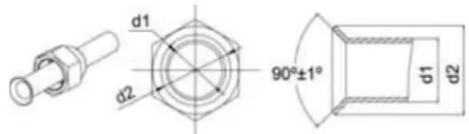
Make sure that the pipe is cut at a perfect 90^ angle. Refer to the image below for guidance.
text_image
90° Oblique Rough WarpedFigure 5.
NOTE: Be extra careful not to damage, dent, or deform the pipe while cutting. This will drastically reduce the operating efficiency of the unit.
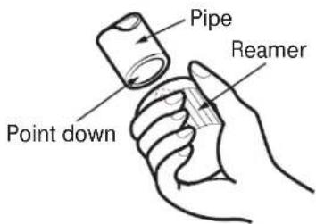
Step 2: Deburring
Burrs will affect the air-tight seal of the refrigerant piping connection. They must be completely removed.
- Hold the pipe at a downward angle to prevent burrs from falling into the pipe.
- Using a reamer or deburring tool, remove all inside and outside burrs from the cut section of the pipe.
- After cutting and deburing, never allow tubing to be exposed to the atmosphere. Tightly seal cut ends with PVC tape.
text_image
Pipe Reamer Point downFigure 6.
NOTE: Flaring step is only necessary if the piping extensions included with the heat pump cannot be used.
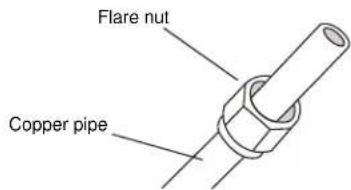
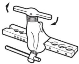
Step 3: Flaring
Proper flaring is essential to achieve an airtight seal.
- Ensure there is enough insulation to protect the entire line set from end to end.
- Use the flare nuts from the accessories pouch, located in the indoor unit packaging. Fit the nut on the tubing to be flared.
text_image
Flare nut Copper pipeFigure 7.
Conventional Line Set Installation: Pipe Bending (Cont.)
Step 3: Flaring (cont)
- Remove the seal over the exposed end, and place the tube into the R-454B flaring tool.
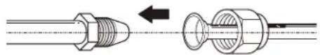
Figure 8.
- Run the tube against the flaring tool pipe stop, and clamp the form on the tube.
- Rotate the handle of the die clockwise until the clutch releases, then remove the flared tubing from the form.
text_image
Flare form A Pipe A = ~1/16" (1.6mm)Figure 10.
- Examine the flare to make sure there are no imperfections on the lip of the flare, and that the back of the flare exactly fits the seat of the flare nut.
natural_image
Mechanical clamp or lever assembly with rotating arrows indicating motion (no text or symbols)Figure 11.
Conventional Line Set Installation: Pipe Connection
- Attach the flare nuts to the outdoor Service Valve, Torque the fittings according to the specifications shown in the torque chart below.
NOTE: Forced fastening without careful centering may damage the threads and cause a refrigerant leak.
| Pipe Diameter(∅) Fastening torque | |
| Liquid side 6.35mm(1/4") 18N.m/ | 3.3Ft.lbs |
| Liquid/ Gas side 9.52mm(3/8") 42 N.m/ | 30.1Ft.lbs |
| Gas side 12.7mm(1/2") 55N.m/ | 6Ft.lbs |
| Gas side 15.88mm(5/8") 60 N.m/ | 4.3Ft.lbs |
| Gas side 19.05mm(3/4") 100N.m/ | 73.8Ft.lbs |
- Add additional refrigerant charge if needed before you open outdoor service valves
- Record the amount of refrigerant added in permanent ink at the line set length location entered earlier.
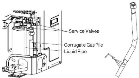
text_image
Service Valves Corrugate Gas Pile Liquid PipeFigure 12.
- Two wrenches are required to join the flare connection; one standard wrench and one torque wrench adjusted to the proper settings.
- Repeat the process for attaching the other end of the line set.
Half union
Flare nut


Spanner
Torque wrench
Figure 13.
Conventional Line Set Installation: Pipe Connection (Cont.)
Pipe Matching Capabilities of Pipe Extensions
| Model Extension | Extension Type | Extension Length (in) | Line Set Receiving End Pipe Diameter (in) | Flared End Pipe Diameter (in) | Line Set Connection Type | |
| 24K | Suction Extension | Flexible 7-3/4 | 3/4 5/8 | Braze and Mechanical | ||
| Liquid Extension 3/8 3/8 | Braze and Mechanical | |||||
| 36K | Suction Extension | Flexible 33-1/2 | 3/4 3/4 | Braze and Mechanical | ||
| 7/8 3/4 Braze | ||||||
| Liquid Extension 3/8 3/8 | Braze and Mechanical | |||||
| 60K | Suction Extension | Flexible 35-3/8 | 3/4 3/4 | Braze and Mechanical | ||
| 7/8 3/4 Braze | ||||||
| Liquid Extension 3/8 3/8 | Braze and Mechanical | |||||
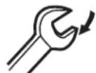
IMPORTANT: A 5/16" female by 1/4" male adapter will be required to connect conventional gauge hoses to the service valves.
text_image
Low side Low Side Valve Manifold Gauge High Side High Side Valve Refrigerant Lines (to indoor unit) Liquid Valve Gas Valve Service Port Cap Refrigerant Hose Vacuum Pump Connection Pipe Cap Service Pipe Cap Refrigerant HoseFigure 14.
NOTE: It shows the gauge connection will need to have the high side gauge hose connected to the high side liquid valve so both lines can be evacuated and leak checked.
Conventional Line Set Installation: Pipe Connection (Cont.)
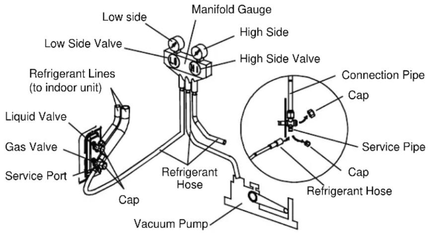
Typical Existing Expansion Valve Removal Typical Existing Fixed Orifice Removal Procedure
text_image
TWO-PIECE PATCH PLATE (UNCASED COIL ONLY) DISTRIBUTOR TUBES STUB END LIQUID LINE ORIFICE HOUSING EXPANSION VALVE TEFLON® RING SENSING LINE TEFLON® RING DISTRIBUTOR ASSEMBLY EQUALIZER LINE LIQUID LINE ASSEMBLY WITH BRASS NUT MALE EQUALIZER LINE FITTING SENSING BULB VAPOR LINE LIQUID LINEFigure 15. Remove Expansion Valve (Uncased Coil Shown)
- On fully cased coils, remove the coil access and plumbing panels.
- Remove any shipping clamps from the liquid line and distributor assembly.
- Disconnect the equalizer line from the fitting on the vapor line.
- Remove the vapor line sensing bulb.
- Disconnect the liquid line from the expansion valve at the liquid line assembly.
- Disconnect the expansion valve from the liquid line orifice housing. Take care not to twist or damage distributor tubes during this process.
- Remove and discard expansion valve and the two Teflohrings.
- Use a field-provided fitting to temporarily reconnect the liquid line to the indoor unit's liquid line orifice housing.
text_image
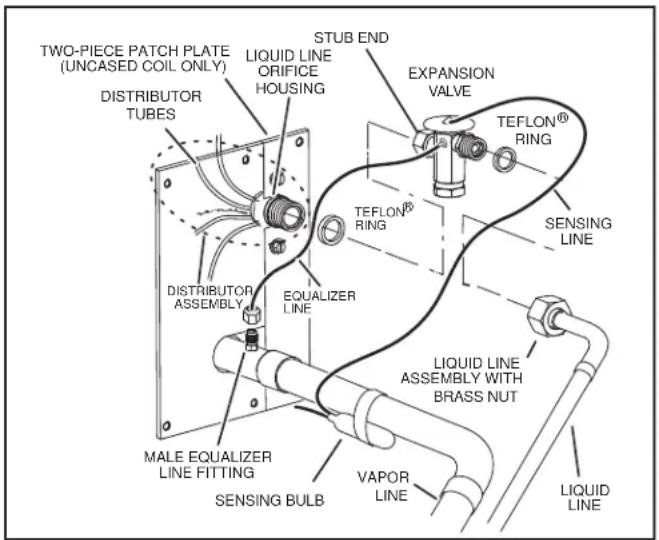
DISTRIBUTOR TUBES LIQUID LINE ORIFICE HOUSING TEFLON® RING FIXED ORIFICE BRASS NUT DISTRIBUTOR ASSEMBLY REMOVE AND DISCARD WHITE TEFLON® SEAL (IF PRESENT) LIQUID LINE ASSEMBLY (INCLUDES STRAINER)Figure 16. Remove Fixed Orifice (Uncased Coil Shown)
- On fully cased coils, remove the coil access and plumbing panels.
- Remove any shipping clamps from the liquid line and distributor assembly.
- Using two wrenches (one to hold the orifice housing and one to remove the brass nut), disconnect liquid line from liquid line orifice housing. Take care not to twist or damage distributor tubes during this process.
- Remove and discard fixed orifice, valve stem assembly (if present) and Teflon® washer, as shown in Figure 3.
- Use a field-provided fitting to temporarily reconnect the liquid line to the indoor unit's liquid line orifice housing.
Conventional Line Set Installation: Pipe Connection (Cont.)
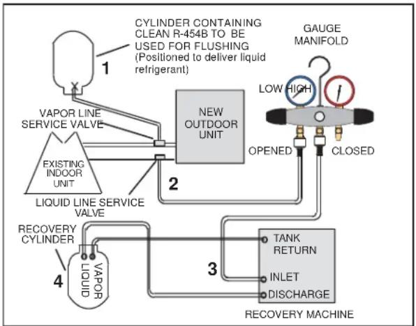
Connect Gauges and Equipment for Flushing Procedure
flowchart
graph TD
    A["RECOVERY CYLINDER"] --> B["VAPOR LINE SERVICE VALVE"]
    B --> C["EXISTING INDOOR UNIT"]
    C --> D["Liquid LINE SERVICE VALVE"]
    D --> E["NEW OUTDOOR UNIT"]
    E --> F["TANK RETURN"]
    F --> G["INLET"]
    G --> H["DISCHARGE"]
    H --> I["RECOVERY MACHINE"]
    I --> J["OPENED"]
    J --> K["CLOSED"]
    K --> L["GAUGE MANIFOLD"]
    L --> M["LOW HIGH"]
    M --> N["1"]
    N --> O["CYLINDER CONTAINING CLEAN R-454B TO BE USED FOR FLUSHING (Positioned to deliver liquid refrigerant)"]
Figure 17. Connecting Gauges
- Cylinder with clean R-454B (positioned to deliver liquid refrigerant) to the vapor service valve.
- Refrigerant gauge set (low side) to the liquid line valve.
- Refrigerant gauge set center port to inlet on the recovery machine with an empty recovery tank connected to the gauge set.
- Connect recovery tank to recovery machine per machine instructions.
Flushing Line Sets
If the unit will be installed in an existing system that uses an indoor unit or line sets charged with R-22 refrigerant, installer must perform the following flushing procedure.
NOTE: Existing system components (including line set and indoor coil) must be an AHRI match with the unit in order to fulfill unit warranty requirements.
WARNING
Fire, Explosion and Personal Safety hazard. Failure to follow this warning could result in damage, personal injury or death.
Never use oxygen to pressurize or purge refrigeration lines. Oxygen, when exposed to a spark or open flame, can cause fire and/or an explosion, that could result in property damage, personal injury or death.
WARNING

such as nitrogen to pressurize a refrigeration or air conditioning system, use a regulator that can control the pressure down to 1 or 2 psig (6.9 to 13.8 kPa).
WARNING
Refrigerant must be reclaimed in ational and local codes.
- Set the recovery machine for liquid recovery and start the recovery machine. Open the gauge set valves to allow the recovery machine to pull a vacuum on the existing system line set and indoor unit coil.
- Position the cylinder of clean R-454B for delivery of liquid refrigerant and open its valve to allow liquid refrigerant to flow into the system through the vapor line valve. Allow the refrigerant to pass from the cylinder and through the line set and the indoor unit coil before it enters the recovery machine.
- After all of the liquid refrigerant has been recovered, switch the recovery machine to vapor recovery so that all of the R-454B vapor is recovered. Allow the recovery machine to pull the system down to 0.
- Close the valve on the inverted R-454B drum and the gauge set valves. Pump the remaining refrigerant out of the recovery machine and turn the machine off.
Refrigerant Piping - Install Indoor Expansion Valve
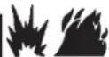
This outdoor unit is designed for use in systems that include a heat pump expansion valve metering device at the indoor coil. See the Product Specifications for approved expansion valve kit match-ups and application information. The expansion valve unit can be installed internal or external to the indoor coil. In applications where an uncased coil is being installed in a field-provided plenum, install the expansion valve in a manner that will provide access for future field service of the expansion valve. Refer to below illustration for reference during installation of expansion valve unit.
INDOOR EXPANSION VALVE INSTALLATION
text_image
(Uncased Coil Shown) TWO PIECE PATCH PLATE (UNCASED COIL ONLY) LIQUID LINE ORIFICE HOUSING STUB END EXPANSION VALVE TEFLON® RING SENSING LINE DISTRIBUTOR TUBES TEFLON® RING EQUALIZER LINE DISTRIBUTOR ASSEMBLY MALE EQUALIZER LINE FITTING (SEE EQUALIZER LINE INSTALLATION FOR FURTHER DETAILS) VAPOR LINE LIQUID LINE ASSEMBLY WITH BRASS NUT LIQUID LINE NOTE - Sensing bulb insulation is required if mounted external to the coil casing.EQUALIZER LINE INSTALLATION
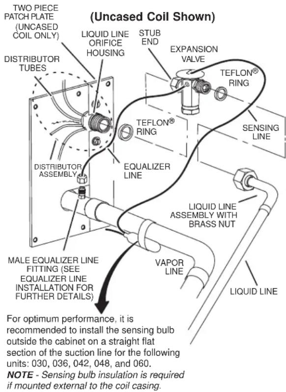
1 - Remove and discard either the flare seal cap or flare nut with copper flare seal bonnet from the equalizer line port on the vapor line as illustrated in the figure below.
2 - Remove the field-provided fitting that temporarily reconnected the liquid line to the indoor unit's distributor assembly.
text_image
FLARE SEAL CAP FLARE NUT OR COPPER FLARE SEAL BONNET MALE BRASS EQUALIZER LINE FITTING VAPOR LINE3 - Install one of the provided Teflon ^® rings around the stubbed end of the check expansion valve and lightly lubricate the connector threads and expose surface of the Teflon ^® ring with refrigerant oil.
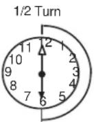
4 - Attach the stubbed end of the check expansion valve to the liquid line orifice housing. Finger tighten and use an appropriately sized wrench to turn an additional 1/2 turn clockwise as illustrated in the figure above, or tighten to 20 ft-lb.
5 - Place the remaining Teflon ^® washer around the other end of the check expansion valve. Lightly lubricate connector threads and expose surface of the Teflon ^® ring with refrigerant oil.
6 - Attach the liquid line assembly to the check expansion valve. Finger tighten and use an appropriately sized wrench to turn an additional 1/2 turn clockwise as illustrated in the figure above or tighten to 20 ft-lb.
SENSING BULB INSTALLATION
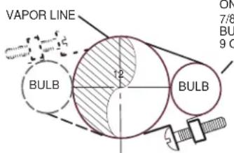
1 - Attach the vapor line sensing bulb in the proper orientation as illustrated to the right using the clamp and screws provided.
NOTE - Though it is preferred to have the sensing bulb installed on a horizontal run of the vapor line, installation on a vertical run of piping is acceptable if necessary.
NOTE - Confirm proper thermal contact between vapor line and check/expansion bulb before insulating the sensing bulb once installed.
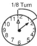
2 - Connect the equalizer line from the check expansion valve to the equalizer vapor port on the vapor line. Finger tighten the flare nut plus 1/8 turn (7 ft-lbs) as illustrated below.
text_image
VAPOR LINE BULB 12 BULB 7/8 BU 9 CON LINES SMALLER THAN 7/8", MOUNT SENSING BULB AT EITHER THE 3 OR 9 O'CLOCK POSITION.
text_image
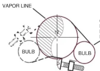
VAPOR LINE 12 BULB 5 BULBON 7/8" AND LARGER LINES, MOUNT SENSING BULB AT EITHER THE 4 OR 8 O'CLOCK POSITION.
NOTE - NEVER MOUNT THE SENSING BULB ON BOTTOM OF LINE.
INSTALLATION INSTRUCTIONS
Refrigerant Piping - Brazing Procedures
1. CUT AND DE-BUR
Cut ends of the refrigerant lines square (free from nicks or dents) and debur the ends. The pipe must remain round. Do not crimp end of the line.
2. CAP AND CORE REMOVAL
Remove service cap and core from both the vapor and liquid line service ports.

text_image
CUT AND DEBUR LINE SET SIZE MATCHES SERVICE VALVE CONNECTION COPPER TUBE STUB REDUCER SERVICE VALVE CONNECTION LINE SET SIZE IS SMALLER THAN CONNECTION REFRIGERANT LINE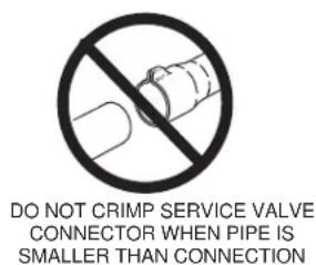
text_image
DO NOT CRIMP SERVICE VALVE CONNECTOR WHEN PIPE IS SMALLER THAN CONNECTION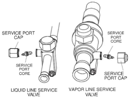
text_image
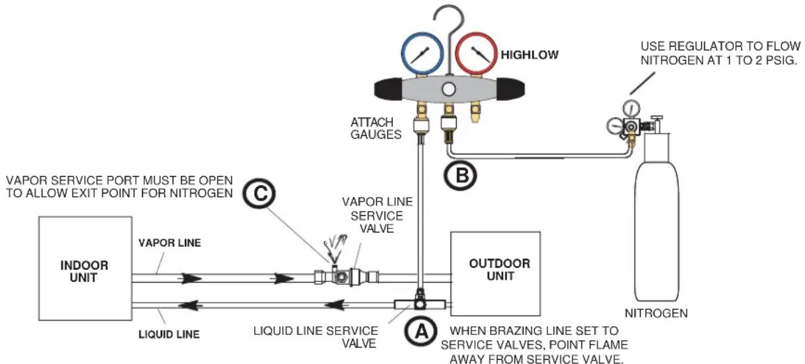
SERVICE PORT CAP SERVICE PORT CORE LIQUID LINE SERVICE VALVE SERVICE PORT CORE SERVICE PORT CAP VAPOR LINE SERVICE VALVE3. ATTACH THE MANIFOLD GAUGE SET FOR BRAZING LIQUID AND VAPOR LINE SERVICE VALVES
Flow regulated nitrogen (at 1 to 2 psig) through the low-side refrigeration gauge set into the liquid line service port valve, and out of the vapor line service port valve.
A - Connect gauge set low pressure side to liquid line service valve (service port).
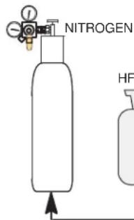
B - Connect gauge set center port to bottle of nitrogen with regulator.
C - Remove core from valve in vapor line service port to allow nitrogen to escape.
flowchart
graph TD
    A["INDOOR UNIT"] --> B["VAPOR LINE"]
    B --> C["Liquid Line"]
    C --> D["LIQUID LINE SERVICE VALVE"]
    D --> E["VAPOR LINE SERVICE VALVE"]
    E --> F["ATTACH GAUGES"]
    F --> G["HIGHLOW"]
    G --> H["OUTDOOR UNIT"]
    H --> I["NITROGEN"]
    style A fill:#f9f,stroke:#333
    style H fill:#ccf,stroke:#333
    note right of A: "VAPOR SERVICE PORT MUST BE OPEN TO ALLOW EXIT POINT FOR NITROGEN"
    note right of H: "USE REGULATOR TO FLOW NITROGEN AT 1 TO 2 PSIG."
    note right of H: "WHEN BRAZING LINE SET TO SERVICE VALVES, POINT FLAME AWAY FROM SERVICE VALVE."
    note right of H: "A WHEN BRAZING LINE SET TO SERVICE VALVES, POINT FLAME AWAY FROM SERVICE VALVE."
NOTE: Use a manifold gauge set designed for use on R-454B refrigerant systems.
WARNING

Before brazing, ensure the system is fully recovered of all refrigerant. Application of a brazing torch to a pressurized system may result in ignition of the refrigerant and oil mixture. Check the high and low pressures before applying heat.
WARNING
Brazing alloys and flux contain
materials which are hazardous to your health.
Avoid breathing vapors or fumes from brazing operations. Perform operations only in well-ventilated areas.
Wear gloves and protective goggles or face shield to protect against burns.
Wash hands with soap and water after handling brazing alloys and flux.
Refrigerant Piping - Brazing Procedures (Cont.)
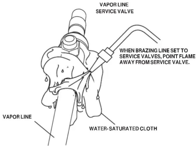
4. WRAP SERVICE VALVES
To help protect service valve seals during brazing, wrap water-saturated cloths around service valve bodies and copper tube stubs. Use additional water-saturated cloths underneath the valve body to protect the base paint.
5. TEST FOR LEAKS
Flow regulated nitrogen (at 1 to 2 psig) through the refrigeration gauge set into the valve stem port connection on the liquid service valve and out of the vapor valve stem port. See steps 3A, 3B and 3C on manifold gauge set connections.
6. BRAZE LINE SET
Wrap both service valves with water-saturated cloths as illustrated here and as mentioned in step 4, before brazing to line set. Cloths must remain water-saturated throughout the brazing and cool-down process.
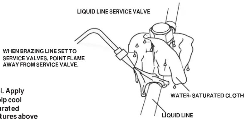
text_image
LIQUID LINE SERVICE VALVE WHEN BRAZING LINE SET TO SERVICE VALVES, POINT FLAME AWAY FROM SERVICE VALVE. I. Apply lip cool drated tures above WATER-SATURATED CLOTH LIQUID LINEIMPORTANT — Allow braze joint to cool. Apply additional water-saturated cloths to help cool brazed joint. Do not remove water-saturated cloths until piping has cooled. Temperatures above 250°F will damage valve seals.
WARNING
FIRE, PERSONAL INJURY, OR PROPERTY
DAMAGE. may result if you do not wrap a water-saturated cloth around both liquid and suction line service valve bodies and copper tube stub while brazing the line set! The braze, when complete, must be quenched with water to absorb any residual heat.
Do not open service valves until refrigerant lines and indoor coil have been leak-tested and evacuated. Refer to the Leak Test and Evacuation section of this manual.
text_image
VAPOR LINE SERVICE VALVE WHEN BRAZING LINE SET TO SERVICE VALVES, POINT FLAME AWAY FROM SERVICE VALVE. VAPOR LINE WATER-SATURATED CLOTH7. PREPARATION FOR NEXT STEP
After all connections have been brazed, disconnect manifold gauge set from service ports. Apply additional water-saturated cloths to both services valves to cool piping. Once piping is cool, remove all water-saturated cloths.
Leak Test and Evacuation

flowchart
graph TD
    A["NITROGEN"] --> B["HFC - 454B"]
    B --> C["LEAK TEST"]
    C --> D["MANIFOLD GAUGE SET"]
    D --> E["OUTDOOR UNIT"]
    E --> F["TO VAPOR SERVICE VALVE"]
    F --> G["A"]
    G --> H["High"]
    G --> I["LOW"]
    style A fill:#f9f,stroke:#333
    style B fill:#ccf,stroke:#333
    style C fill:#cff,stroke:#333
    style D fill:#ffc,stroke:#333
    style E fill:#cfc,stroke:#333
    style F fill:#fcc,stroke:#333
    style G fill:#fcf,stroke:#333
    note right of B NOTE: Position canister to deliver liquid refrigerant.
1. CONNECT GAUGE SET
A. Connect the high pressure hose of an HFC-454B manifold gauge set to the vapor valve service port.
NOTE: Normally, the high pressure hose is connected to the liquid line port. However, connecting it to the vapor port better protects the manifold gauge set from high pressure damage.
B. With both manifold valves closed, connect the nitrogen container to the center port of the manifold gauge set.
2. TEST FOR LEAKS
After the line set has been connected to the indoor and outdoor units, check the line set connections and indoor unit for leaks. Use the following procedure to test for leaks:
A. With both manifold valves closed, connect the nitrogen container to the center port of the manifold gauge set.
B. Open the high pressure side of the manifold to allow HFC-454B into the line set and indoor unit. Weigh in a trace amount of HFC-454B. [A trace amount is a maximum of two ounces (57 g) refrigerant or three pounds (31 kPa) pressure.] Close the valve on the HFC-454B cylinder and the valve on the high pressure side of the manifold gauge set. Disconnect the HFC-454B cylinder.
C. Connect a cylinder of nitrogen with a pressure regulating valve to the center port of the manifold gauge set.
D. Adjust nitrogen pressure to 150 psig (1034 kPa). Open the valve on the high side of the manifold gauge set in order to pressurize the line set and the indoor unit.
E. After a few minutes, open one of the service valve ports and verify that the refrigerant added to the system earlier is measurable with a leak detector.
F. After leak testing, disconnect gauges from service ports.
NOTE - Service valve cores remain removed for the following evacuation procedure.
3. CONNECT GAUGE SET
NOTE: Remove cores from service valves (if not already done).
A. Connect low side of manifold gauge set with 1/4 SAE in-line tee to vapor line service valve.
B. Connect high side of manifold gauge set to liquid line service valve.
C. Connect available micron gauge connector on the 1/4 SAE in-line tee.
D. Connect the vacuum pump (with vacuum gauge) to the center port of the manifold gauge set. The center port line will be used later for both the HFC-454B and nitrogen containers.
Leak Test and Evacuation (Cont.)
WARNING
Possible
equipment damage.
Avoid deep vacuum operation. Do not use compressors to evacuate a system. Extremely low vacuum can cause internal arcing and compressor failure. Damage caused by deep vacuum operation will void warranty.
text_image
NITROGEN HFNOTE - Position canister to deliver liquid refrigerant.
EVACUATE THE SYSTEM
EVACUATION
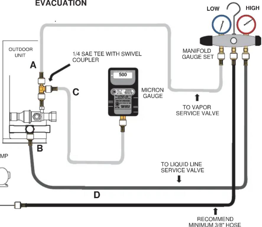
flowchart
graph TD
    A["OUTDOOR UNIT"] --> B["A"]
    B --> C["C"]
    C --> D["D"]
    D --> E["RECOMMEND MINIMUM 3/8" HOSE"]
    F["MICRON GAUGE"] --> G["1/4 SAE TEE WITH SWIVEL COUPLER"]
    G --> H["TO VAPOR SERVICE VALVE"]
    H --> I["MANIFOLD GAUGE SET"]
    I --> J["LOW"]
    I --> K["HIGH"]
    L["MP"] --> M["B"]
    M --> N["D"]
    N --> O["TO LIQUID LINE SERVICE VALVE"]
4. EVACUATE THE SYSTEM
A. Open both manifold valves and start the vacuum pump.
B. Evacuate the line set and indoor unit until a slight vacuum is indicated on the micron gauge (approximately 23,000 microns or 29.01 inches of mercury).
NOTE - During the early stages of evacuation, it is desirable to close the manifold gauge valve at least once. A rapid rise in pressure indicates a relatively large leak. If this occurs, repeat the leak testing procedure.
NOTE - The term absolute pressure means the total actual pressure above absolute zero within a given volume or system. Absolute pressure in a vacuum is equal to atmospheric pressure minus vacuum pressure.
C. When the absolute pressure reaches 23,000 microns (29.01 inches of mercury), perform the following:
- Close manifold gauge valves.
- Close valve on vacuum pump.
- Turn off vacuum pump.
- Disconnect manifold gauge center port hose from vacuum pump.
- Attach manifold center port hose to a nitrogen cylinder with pressure regulator set to 150 psig (1034 kPa) and purge the hose.
- Open manifold gauge valves to break the vacuum in the line set and indoor unit.
- Close manifold gauge valves.
D. Shut off the nitrogen cylinder and remove the manifold gauge hose from the cylinder. Open the manifold gauge valves to release the nitrogen from the line set and indoor unit.
E. Reconnect the manifold gauge to the vacuum pump, turn the pump on, and continue to evacuate the line set and indoor unit until the absolute pressure does not rise above 500 microns (29.9 inches of mercury) within a 20-minute period after shutting off the vacuum pump and closing the manifold gauge valves.
F. When the absolute pressure requirement above has been met, disconnect the manifold hose from the vacuum pump and connect it to a cylinder of HFC-454B positioned to deliver liquid refrigerant. Open the manifold gauge valve 1 to 2 psig in order to release the vacuum in the line set and indoor unit.
INSTALLATION INSTRUCTIONS
Leak Test and Evacuation (Cont.)
4. EVACUATE THE SYSTEM (Cont.)
G. Perform the following:
- Close manifold gauge valves.
- Shut off HFC-454B cylinder.
- Reinstall service valve cores by removing manifold hose from service valve. Quickly install cores with core tool while maintaining a positive system pressure.
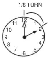
- Replace stem caps and finger tighten them, then tighten an additional one-sixth (1/6) of a turn as illustrated.
H. Open suction service valve first before liquid valve to release the unit charge into the system. Replace valve caps and tighten (8 ft. lb.). Caps are the primary seal.
Electrical - Circuit Sizing and Wire Routing
In the U.S.A., wiring must conform with current local codes and the current National Electric Code (NEC). In Canada, wiring must conform with current local codes and the current Canadian Electrical Code (CEC).
Refer to the furnace or air handler installation instructions for additional wiring application diagrams and refer to unit nameplate for minimum circuit ampacity and maximum overcurrent protection size.
24VAC Transformer
Use the transformer provided with the furnace or air handler for low-voltage control power (24VAC - 40 VA minimum).
Thermostat Control and Low Voltage Control Wiring
Conventional 24VAC Thermostat Control
The NS18H variable capacity unit may be installed using a conventional 24VAC two-stage cooling or single-stage cooling thermostat.
The NS18H unit will provide full variable capacity operation when installed with a conventional 24VAC two stage heat pump or single-stage heat pump thermostat. The NS18H outdoor control has advanced control algorithms, which provide true variable speed capacity operation by modulating the compressor speed to achieve the target suction pressure set point in cooling mode, and liquid pressure set point in heating mode.
When utilizing a two-stage conventional 24VAC thermostat, six wires are required to control the outdoor unit (R, C, W1, O, Y1 and Y2). Refer to the NS18H field wiring diagram for a conventional 24VAC two-stage thermostat.
When utilizing a single conventional 24VAC thermostat, five wires are required to control the outdoor unit (R, C, W1, O, and Y1) and Y1 is jumpered to Y2 in the outdoor unit. Note that the published performance data is based upon the use of a two-stage thermostat. Refer to the NS18H field wiring diagram for a conventional 24VAC single-stage thermostat.
| Thermostat Type Indoor Unit Type | Qty. of Wires to | NS18H Terminal Strip Connections | Unit Operation | Field Wiring Diagram | |
| Conventional 24VAC 2-Stage Cooling Thermostat | Any Furnace or Air Handler | 6 R, C, | W1, O, Y1, Y2 | Full Variable Capacity Operation Controlled by NS18H Unitary Control Using Suction Pressure | Page 33 |
| Conventional 24VAC Single-Stage Cooling Thermostat | Any Furnace or Air Handler | 5 | R, C, W1, O, Y1 (Jumper Y1 to Y2) | Full Variable Capacity Operation Controlled by NS18H Unitary Control Using Suction Pressure | Page 32 |
Table 5. NS18H Thermostat Control Options
WARNING

trical Shock Hazard!
Can cause injury or death. Unit must be properly grounded in accordance with national and local codes.
Line voltage is present at all components when unit is not in operation on units with single-pole contactors. Disconnect all remote electric power supplies before opening access panel. Unit may have multiple power supplies.
WARNING
Fire Hazard.
Use of aluminum wire with this product may result in a fire, causing property damage, severe injury or death. Use copper wire only with this product.
WARNING
Failure to use properly sized wiring and circuit breaker may result in property damage. Size wiring and circuit breaker(s) per Technical Specifications and unit rating plate.
WARNING
ELECTROSTATIC DISCHARGE (ESD)
Precautions and Procedures
Electrostatic discharge can affect electronic components. Take care during unit installation and service to protect the unit's electronic controls. Precautions will help to avoid control exposure to electrostatic discharge by putting the unit, the control and the technician at the same electrostatic potential. Touch hand and all tools on an unpainted unit surface before performing any service procedure to neutralize electrostatic charge.
INSTALLATION INSTRUCTIONS
Install Thermostat
Install room thermostat (ordered separately) on an inside wall approximately in the center of the conditioned area and 5 feet (1.5m) from the floor. It should not be installed on an outside wall or where it can be affected by sunlight or drafts.
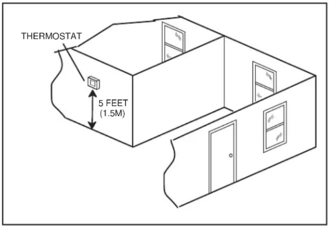
text_image
THERMOSTAT 5 FEET (1.5M)Figure 18.
NOTE: 24VAC, Class II circuit connections are made in the control panel.
Size Circuit and Install Service Disconnect Switch
Refer to the unit nameplate for minimum circuit ampacity, and maximum fuse or circuit breaker (HACR per NEC). Install power wiring and properly sized disconnect switch.
NOTE: Units are approved for use only with copper conductors. Ground unit at disconnect switch or connect to an earth ground.
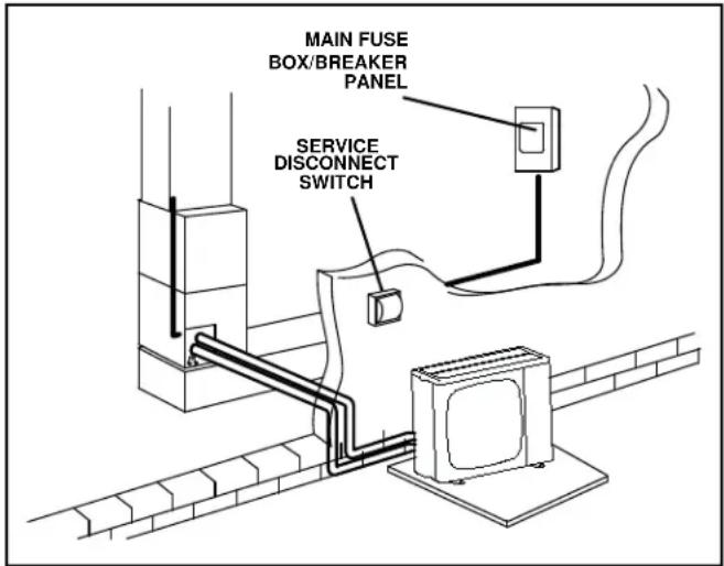
text_image
MAIN FUSE BOX/BREAKER PANEL SERVICE DISCONNECT SWITCHFigure 19.
24K/36K
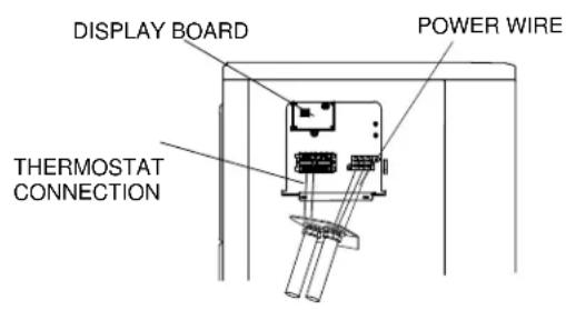
text_image
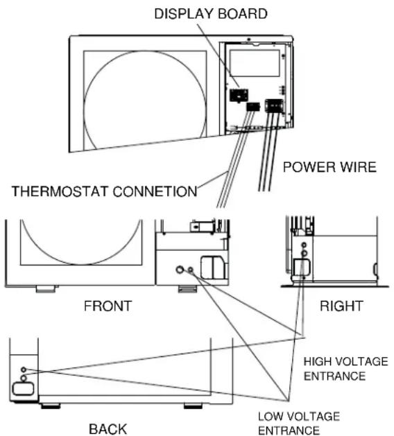
DISPLAY BOARD POWER WIRE THERMOSTAT CONNECTION60K
text_image
DISPLAY BOARD POWER WIRE THERMOSTAT CONNECTION FRONT RIGHT HIGH VOLTAGE ENTRANCE BACK LOW VOLTAGE ENTRANCEFigure 20.
NOTE: Select the appropriate conduit opening for the wire size used.
INSTALLATION INSTRUCTIONS
Route Control Wires Route High Voltage and Ground Wires
| Wire Run Length AWG | # Insulation Type | |
| Less than 100' (30m) 18 | Temperature Rating35°C Minimum | |
| More than 100' (30m) 16 | ||
Table 6. Conventional 24VAC Thermostat Wiring
Any excess high voltage field wiring should be trimmed and secured away from any low voltage field wiring. To facilitate a conduit, a cutout is located on the bottom of the control box. Connect conduit to the control box using a proper conduit fitting.
Connect the 208/230 high voltage power supply from the disconnect to the NS18H contactor as shown. Connect the ground wire from the power supply to the unit ground lug connection.
WARNING
Improper installation, adjustment, alteration, service or maintenance can cause property damage, personal injury or loss of life.
Installation and service must be performed by a licensed professional HVAC installer (or equivalent) or a service agency.
WARNING
All systems equipped with at least 4 lbs of low-GWP A2L-classified refrigerant are required to have a refrigerant leak detection system installed to prevent the build up of low-flammable refrigerant in enclosed spaces of the HVAC equipment. A refrigerant detection system may be required for systems that have less than 4 lbs of low-GWP refrigerant. For more information on this, contact Technical Support.
Installing OEM low GWP residential HVAC equipment without a refrigerant detection system may lead to a fire hazard within the home in the event of a refrigerant leak.
WARNING
The RDS Non-Communicating Blower Control Board has been tested with OEM matched coils only. Do not use a non-OEM refrigerant detection system controller or non-OEM leak sensor with OEM coils. Do not use the RDS Non-Communicating Blower Control Board with other manufacturer's coils or air handlers.
WARNING
Improper installation of the RDS Non-Communicating Blower Control Board may lead to unreliable equipment operation and possible fire hazard from refrigerant leaks. In addition to installing the RDS Non-Communicating Blower Control Board, considerations must be made regarding sensor mounting location. Please refer to respective OEM air handler, coil, and/or sensor kit installation guides for further details.
CAUTION
Any service personnel installing, decommissioning, or performing maintenance on the unit must be properly trained and certified with low GWP refrigerants. Unit must remain powered except for service.
Certifications
• CSA C22.2 No. 60335-2-40:22; Fourth ed.
• UL 60335-2-40; Fourth ed.
Shipping and Packing List
| Qty | Description Cat. No. | |
| 1 OEM | Low GWP Refrigerant Detection System | 27A05 |
| 2 Mounting Hardware - # 6-18 1” Phillips Drive pan head with dry wall anchor | N/A | |
INSTALLATION INSTRUCTIONS
RDS Wiring Diagrams for Single Stage Heat Pump with Air Handler
Refer to the single and two stage RDS wiring diagrams for proper set up of the refrigerant detection system.
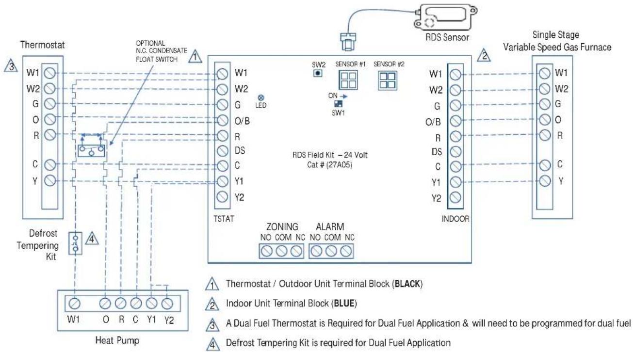
flowchart
graph TD
    A["Thermostat"] -->|W1 W2 G O R C Y| B["Defrost Tempering Kit"]
    B --> C["Heat Pump"]
    C --> D["Optional N.C. CONDENSATE FLOAT SWITCH"]
    D --> E["W1 W2 G O/B R DS C Y1 Y2 TSTAT"]
    E --> F["RDS Field Kit - 24 Volt Cat # (27A05)"]
    F --> G["W1 W2 G O/B R DS C Y1 Y2 ZONING ALARM NO COM NC"]
    G --> H["INDOOR"]
    H --> I["Single Stage Variable Speed Gas Furnace"]
    style A fill:#f9f,stroke:#333
    style B fill:#ccf,stroke:#333
    style C fill:#cfc,stroke:#333
    style D fill:#fcc,stroke:#333
    style E fill:#cff,stroke:#333
    style F fill:#ffc,stroke:#333
    style G fill:#ffc,stroke:#333
    style H fill:#ffc,stroke:#333
    style I fill:#ffc,stroke:#333
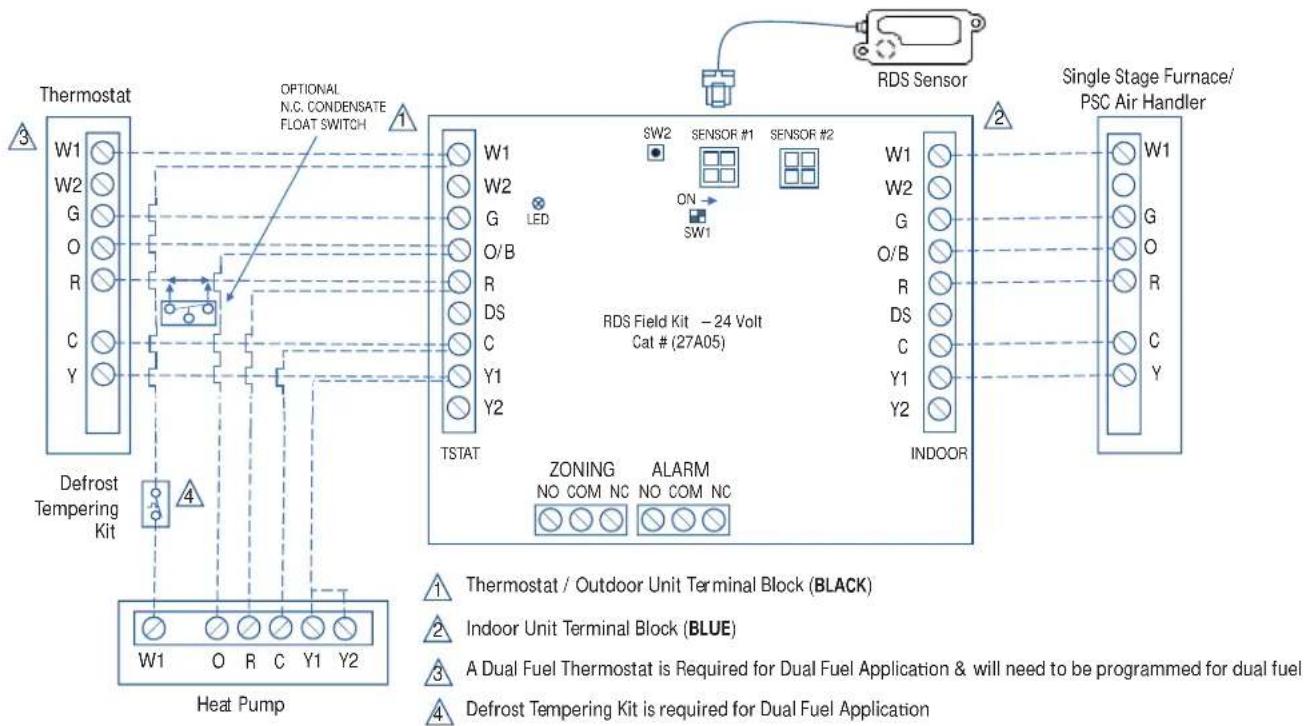
flowchart
graph TD
    A["Thermostat"] -->|W1 W2 G O R C Y| B["Defrost Tempering Kit"]
    B --> C["Heat Pump"]
    C --> D["Optional N.C. CONDENSATE FLOAT SWITCH"]
    D --> E["W1 W2 G O/B R DS C Y1 Y2 TSTAT"]
    E --> F["RDS Field Kit - 24 Volt Cat # (27A05)"]
    F --> G["SW2 SENSOR #1 SENSOR #2"]
    G --> H["INDOOR"]
    H --> I["Single Stage Furnace/PSC Air Handler"]
    style A fill:#f9f,stroke:#333
    style B fill:#ccf,stroke:#333
    style C fill:#cfc,stroke:#333
    style D fill:#fcc,stroke:#333
    style E fill:#cff,stroke:#333
    style F fill:#ffc,stroke:#333
    style G fill:#ffc,stroke:#333
    style H fill:#ffc,stroke:#333
    style I fill:#ffc,stroke:#333
INSTALLATION INSTRUCTIONS
RDS Wiring Diagrams for Single Stage Heat Pump with Air Handler (Cont.)
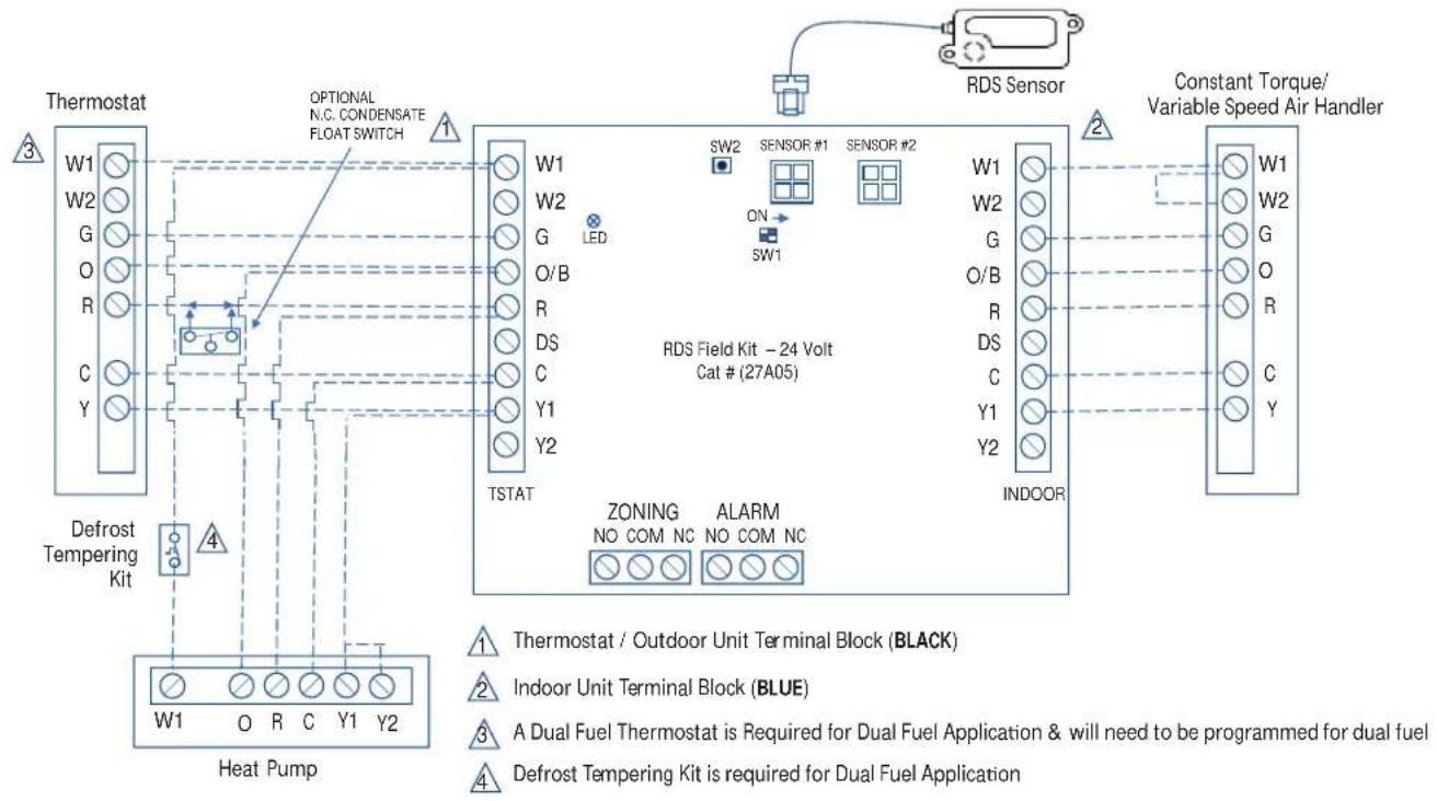
flowchart
graph TD
    A["Thermostat"] --> B["Defrost Tempering Kit"]
    B --> C["Heat Pump"]
    C --> D["Optional N.C. CONDENSATE FLOAT SWITCH"]
    D --> E["TSTAT"]
    E --> F["RDS Field Kit - 24 Volt Cat # (27A05)"]
    F --> G["SW1"]
    F --> H["SW2"]
    F --> I["ON"]
    F --> J["SENSOR #1"]
    F --> K["SENSOR #2"]
    F --> L["INDOOR"]
    F --> M["ZONING NO COM NC ALARM NO COM NC"]
    M --> N["Constant Torque/Variable Speed Air Handler"]
    style A fill:#f9f,stroke:#333
    style B fill:#ccf,stroke:#333
    style C fill:#cfc,stroke:#333
    style D fill:#fcc,stroke:#333
    style E fill:#cff,stroke:#333
    style F fill:#ffc,stroke:#333
    style G fill:#fff,stroke:#333
    style H fill:#fff,stroke:#333
    style I fill:#fff,stroke:#333
    style J fill:#fff,stroke:#333
    style K fill:#fff,stroke:#333
    style L fill:#fff,stroke:#333
    style M fill:#fff,stroke:#333
    style N fill:#fff,stroke:#333
    style O fill:#fff,stroke:#333
    style P fill:#fff,stroke:#333
    style Q fill:#fff,stroke:#333
    style R fill:#fff,stroke:#333
    style S fill:#fff,stroke:#333
    style T fill:#fff,stroke:#333
    style U fill:#fff,stroke:#333
    style V fill:#fff,stroke:#333
    style W fill:#fff,stroke:#333
    style X fill:#fff,stroke:#333
    style Y fill:#fff,stroke:#333
INSTALLATION INSTRUCTIONS
RDS Wiring Diagrams for Two Stage Heat Pump with Two Stage Furnace/ Air Handler
NOTE: Refer to the RDS installation instruction booklet for further information.
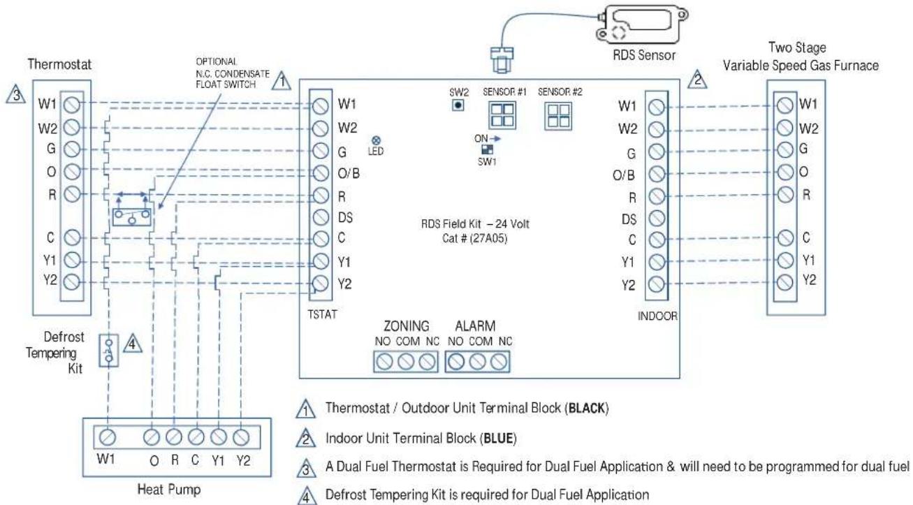
flowchart
graph TD
    A["Thermostat"] --> B["Defrost Tempering Kit"]
    B --> C["Heat Pump"]
    C --> D["Optional N.C. CONDENSATE FLOAT SWITCH"]
    D --> E["TSTAT"]
    E --> F["RDS Field Kit - 24 Volt Cat # (27A05)"]
    F --> G["Indoor Unit Terminal Block (BLACK)"]
    F --> H["Indoor Unit Terminal Block (BLUE)"]
    F --> I["A Dual Fuel Thermostat is Required for Dual Fuel Application & will need to be programmed for dual fuel"]
    F --> J["Defrost Tempering Kit is required for Dual Fuel Application"]
    K["RDS Sensor"] --> L["SW2 SENSOR #1 SENSOR #2"]
    L --> M["ON SW1"]
    M --> N["SW1"]
    N --> O["SW1"]
    O --> P["W1 W2 G O R Y1 Y2"]
    Q["THY1 Y2"] --> R["Optical Control Signals"]
    S["THY2"] --> T["Optical Control Signals"]
    U["THY3"] --> V["Optical Control Signals"]
    W["THY4"] --> X["Optical Control Signals"]
    Y["THY5"] --> Z["Optical Control Signals"]
    AA["THY6"] --> AB["Optical Control Signals"]
    AC["THY7"] --> AD["Optical Control Signals"]
    AE["THY8"] --> AF["Optical Control Signals"]
    AG["THY9"] --> AH["Optical Control Signals"]
    AI["THY10"] --> AJ["Optical Control Signals"]
    AK["THY11"] --> AL["Optical Control Signals"]
    AM["THY12"] --> AN["Optical Control Signals"]
    AO["THY13"] --> AP["Optical Control Signals"]
    AQ["THY14"] --> AR["Optical Control Signals"]
    AS["THY15"] --> AT["Optical Control Signals"]
    AU["THY16"] --> AV["Optical Control Signals"]
    AW["THY17"] --> AX["Optical Control Signals"]
    AY["W1 W2 G O R Y1 Y2"] --> AX
    AX --> AY
    style A fill:#f9f,stroke:#333
    style B fill:#ccf,stroke:#333
    style C fill:#cfc,stroke:#333
    style AD fill:#fcc,stroke:#333
    style AE fill:#cff,stroke:#333
    style AF fill:#ffc,stroke:#333
    style AG fill:#fcc,stroke:#333
    style AH fill:#fcc,stroke:#333
    style AI fill:#fcc,stroke:#333
    style AJ fill:#fcc,stroke:#333
    style AK fill:#fcc,stroke:#333
    style AL fill:#fcc,stroke:#333
    style AM fill:#fcc,stroke:#333
    style AN fill:#fcc,stroke:#333
    style AO fill:#fcc,stroke:#333
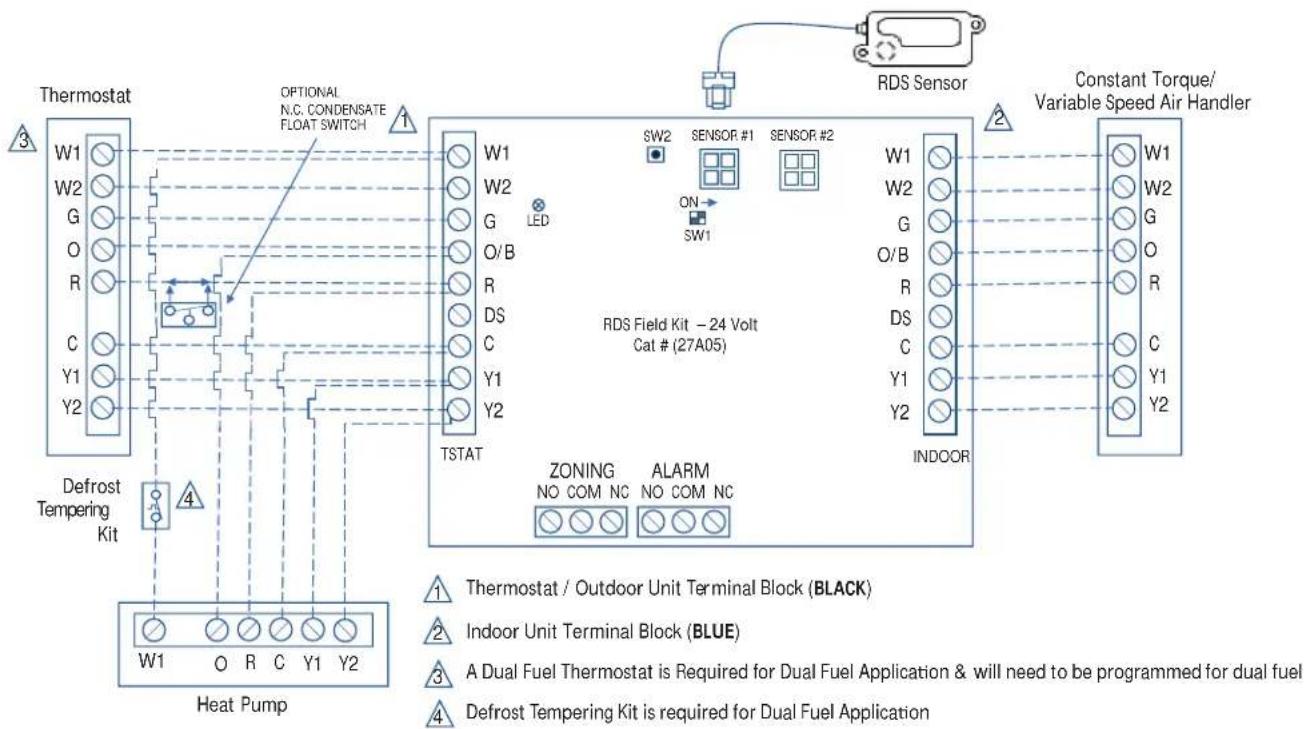
flowchart
graph TD
    A["Thermostat"] -->|W1 W2 G O R C Y1 Y2 Defrost Tempering Kit| B["Defrost Tempering Kit"]
    B --> C["Heat Pump"]
    C --> D["Optional N.C. CONDENSATE FLOAT SWITCH"]
    D --> E["TSTAT"]
    E --> F["RDS Field Kit - 24 Volt Cat # (27A05)"]
    F --> G["SW2 SENSOR #1 SENSOR #2"]
    G --> H["INDOOR"]
    H --> I["Constant Torque/Variable Speed Air Handler"]
    style A fill:#f9f,stroke:#333
    style B fill:#ccf,stroke:#333
    style C fill:#cfc,stroke:#333
    style D fill:#fcc,stroke:#333
    style E fill:#cff,stroke:#333
    style F fill:#ffc,stroke:#333
    style G fill:#cfc,stroke:#333
    style H fill:#cfc,stroke:#333
    style I fill:#cfc,stroke:#333
INSTALLATION INSTRUCTIONS
Outdoor Unitary Control
DIP and Terminals
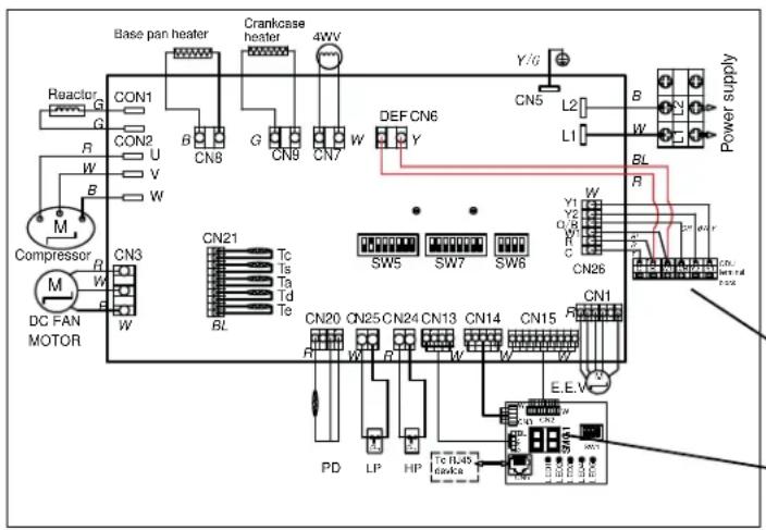
text_image
Base pan heater Crankcase heater 4WV Y/G CN1 CON1 CON2 CN9 G CN9 CN7 W DEF CN6 Y CN5 L2 B W L1 BL Power supply R M U V W R M U V W Compressor CN3 CN21 Tc Ts Td Te SW5 SW7 SW6 CN26 Y1 Y2 CN1 CN20 CN25 CN24 CN13 CN14 CN15 E.E.V. PD LP HP Tc H245 clknkaLP/HP: Low/High Pressure Switch
Tc: Condensing Temp.Sensor
Ts: Condensing Suction Temp.Sensor
Ta: Ambient Temp.Sensor
Td: Compressor Discharge Temp.Sensor
Te: Condensing Out Temp.Sensor
PD: High Pressure Sensor
4WV: 4 Way Valve
RAST TERMINALS FOR
THERMOSTAT WIRING
CONNECTION
DISPLAY BOARD
SW5 function is shown in Table 7
SW7 centralized controller address selection (reserved function),
SW6 test dip (do not move unless tested)
Figure 21. 24K/36K Wiring Diagram
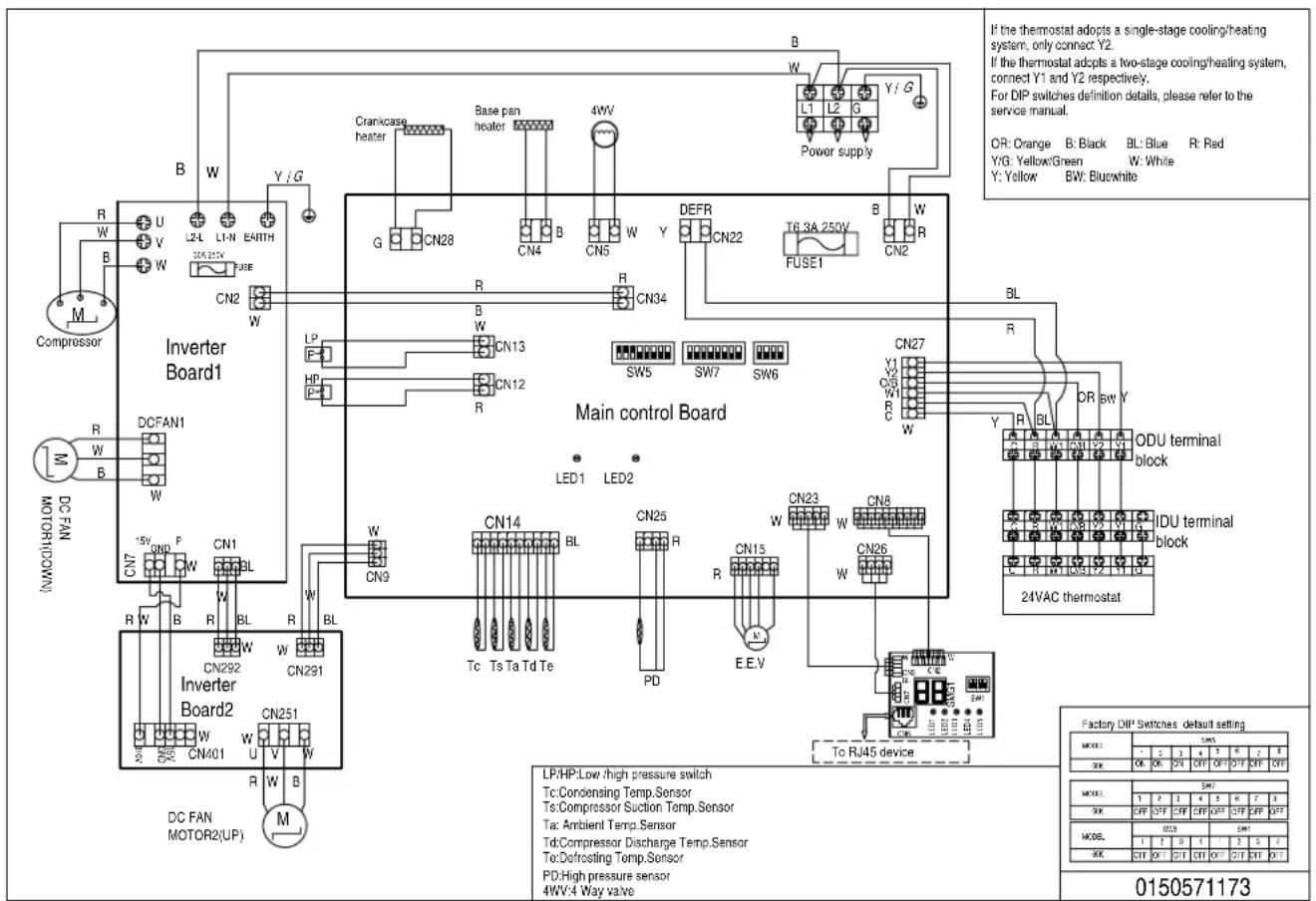
text_image
If the thermostat adopts a single-stage cooling/heating system, only connect Y2. If the thermostat adopts a two-stage cooling/heating system, connect Y1 and Y2 respectively. For DIP switches definition details, please refer to the service manual. OR: Orange B: Black BL: Blue R: Red Y/G: Yellow/Green W: White Y: Yellow BW: Blue/white Power supply Cranixcase heater Base pan heater 4WV G CN28 CN4 B CN5 W Y DEFR CN22 T6.3A 250V B W CN2 CN34 Main control Board CLN13 CN12 R LP HP R SW5 SW7 SW6 ON27 Y1 O/S R C W R BL DR BW Y ODU terminal block IDU terminal block 24VAC thermostat LED1 LED2 CN14 BL CN25 R CN23 W CN8 Tc Ts Ta Td Te PD E.E.V CN9 CN15 CN26 To RJ45 device LP/HP:Low/high pressure switch Tc:Condensing Temp.Sensor Ts:Compressor Suction Temp.Sensor Ta: Ambient Temp.Sensor Td:Compressor Discharge Temp.Sensor To:Defrosting Temp.Sensor PD:High pressure sensor 4WV:4 Way valve Inverter Board1 DC FAN1 DC FAN1000W Inverter Board2 DC FAN MOTOR2(UP) M L2-L L1-N EARTH 3EA-325K FUSE B W Y / G R W B W U V W R W B W W W W CN2 CN1 CN2 CN9 CN14 CN25 R CN23 W CN8 CN292 CN291 CN251 CN292 CN291 CN251 CN292 CN291 CN251 CN292 CN291 CN251 CN292 CN291 CN251 CN292 CN291 CN251 CN292 CN291 CN251 CN292 CN291 CN251 CN292 CN291 CN251 CN292 SN30000000000000000000000000000000000000000000000000000000000000000000000000000000000000000000000000000Figure 22. 60K Wiring Digram
INSTALLATION INSTRUCTIONS
Information labels concerning the outdoor control 2-segment display and DIP operations are available on the unit control panel cover.
Alarm information is provided on the unit control panel cover.
To initiate the NS18H Charge Mode function, install the charge mode of cooling and heating can be adjusted through the dip switch of the display board.
When unit is in the cooling charge mode, 2 - segment display displays the current Subcooling.
The operation mode of DIP switch SW1 on the display board is shown in Table 8. After the system is started, the system needs to be stabilized for 10 minutes. Compare the subcooling value that is displayed after 10 minutes with the target subcooling value in.
To test the supercooling degree in heating mode, an external pressure gauge and thermometer need to be connected, and the pressure and measurement temperature are connected as shown in the Figure 23. The saturation temperature of the refrigerant is checked through Table 10, and the current supercooling degree is obtained by using the temperature measured by the saturation temperature minus the thermometer, and the target supercooling degree is compared with that in.
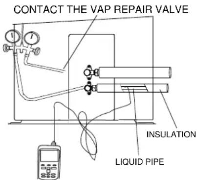
text_image
CONTACT THE VAP REPAIR VALVE INSULATION LIQUID PIPEFigure 23.
| SW5 | ||||||
| SW5_1_2_3ODU Ton | [1] [2] | 3] Outdoor | Unit Size | |||
| ON | ■ | 24K | ||||
| OFF | ■ | ■ | ||||
| ON | ■ | 36K | ||||
| OFF | ■ | ■ | ||||
| ON | ■ | ■ | 48K | |||
| OFF | ■ | |||||
| ON | ■ | ■ | ■ | 60K | ||
| OFF | ||||||
| SW5_4 Communication Mode | ON Reserved | |||||
| OFF 24V Control | ||||||
| SW5_5_6LEAVE ASFACTORYDEFAULT | 24V Control EnergyEfficiency Testing andActual Use of InternalMachine Selection | [5] [6] 24V control indoor unit set | ||||
| OFF OFF IDU | 1 | For AHU | Test & Use | |||
| OFF | ON | IDU 2 | For Coil+Furnace Test & Use | |||
| ON | OFF IDU 3 | For A-coil Test | ||||
| ON | ON | IDU 4 | Reserved | |||
| SW5_7 | 24V Control Heat PumpChangeover Valve | ON | Heating changeover valve: Use this setting ifyour thermostat heating is “B” | |||
| OFF | Cooling changeover valve: Use this setting ifyour thermostat cooling is “O”. | |||||
| SW5_8 | Reserved | ON Reserved | ||||
| OFF | Reserved | |||||
Table 7. Control Board DIP SW5
INSTALLATION INSTRUCTIONS
| SW1 | 1 | 2 | 3 | 4 | |||
| Dehum. 1 | Dehum. 2 | Heating Defrost | Cooling | Heating | |||
| MODE | ON | Default Cooling | Default Heating + Default Defrost | ||||
| OFF | ■ | ■ | ■ | ■ | |||
| ON | ■ | Default Cooling | Default Heating + Strong Defrost | ||||
| OFF | ■ | ■ | ■ | ||||
| ON | ■ | Default Cooling | Comfort Heating or Full-Load Airflow Rate <300 Scfm/ Ton + Default Defrost | ||||
| OFF | ■ | ■ | ■ | ||||
| ON | ■ | ■ | Default Cooling | Comfort Heating or Full-Load Airflow Rate <300 Scfm/ Ton + Strong Defrost | |||
| OFF | ■ | ■ | |||||
| ON | ■ | Dehum. 1 or Full-Load Airflow Rate <300 Scfm/ Ton | Default Heating + Default Defrost | ||||
| OFF | ■ | ■ | ■ | ||||
| ON | ■ | ■ | Dehum. 1 or Full-Load Airflow Rate <300 Scfm/ Ton | Default Heating + Strong Defrost | |||
| OFF | ■ | ■ | |||||
| ON | ■ | ■ | Dehum. 1 or Full-Load Airflow Rate <300 Scfm/ Ton | Comfort Heating or Full-Load Airflow Rate <300 Scfm/ Ton + Default Defrost | |||
| OFF | ■ | ■ | |||||
| ON | ■ | ■ | ■ | Dehum. 1 or Full-Load Airflow Rate <300 Scfm/ Ton | Comfort Heating or Full-Load Airflow Rate <300 Scfm/ Ton + Strong Defrost | ||
| OFF | ■ | ||||||
| ON | ■ | Dehum. 2 or Full-Load Airflow Rate <300 Scfm/ Ton | Default Heating + Default Defrost | ||||
| OFF | ■ | ■ | ■ | ||||
| ON | ■ | ■ | Dehum. 2 or Full-Load Airflow Rate <300 Scfm/ Ton | Default Heating + Strong Defrost | |||
| OFF | ■ | ■ | |||||
| ON | ■ | ■ | Dehum. 2 or Full-Load Airflow Rate <300 Scfm/ Ton | Comfort Heating or Full-Load Airflow Rate <300 Scfm/ Ton + Default Defrost | |||
| OFF | ■ | ■ | |||||
| ON | ■ | ■ | ■ | Dehum. 2 or Full-Load Airflow Rate <300 Scfm/ Ton | Comfort Heating or Full-Load Airflow Rate <300 Scfm/ Ton + Strong Defrost | ||
| OFF | ■ | ||||||
| FORCED & CHARGE MODE | ON | ■ | ■ | TEST MODE | |||
| OFF | ■ | ■ | |||||
| ON | ■ | ■ | ■ | TEST MODE | |||
| OFF | ■ | ||||||
| ON | ■ | ■ | ■ | CHARGE MODE FOR HEATING | |||
| OFF | ■ | ||||||
| ON | ■ | ■ | ■ | ■ | CHARGE MODE FOR COOLING | ||
| OFF | |||||||
| FUNCTION DESCRIPTION | 1. When dehum. mode 1 is effective, it runs the evaporation temperature colder than default modeWhen dehum. mode 2 is effective, it runs the evaporation temperature colder than dehum. mode 1. | ||||||
| 2. When the comfortable heating mode is effective, it runs the evaporation temperature warmer than the default heat pump mode. | |||||||
| 3. The unit will execute a manual defrost at any point if the SW1-4 is moved from the OFF position into the ON position.From that point on the unit will remain in strong defrost mode. If you wish to return to default defrost mode, the switch will need to be manually moved back into the OFF position. | |||||||
| 4. When the unit is in strong defrost mode, the time interval between defrosts will be shorter and the duration of the defrost will be increased. This setting is suitable for areas with colder temperatures and high humidity. | |||||||
| Table 8. Display Board DIP SW1 | |||||||
INSTALLATION INSTRUCTIONS
| Indoor Matchup Subcool Additional | Charge | Indoor Matchup Subcool Additional | Charge | ||||
| 2 Ton HP | 3 Ton HP (cont) | ||||||
| NAM18P1TA5* 46 | 1 lb 2 oz | NCHC36AT5* | 8 10 | 0 lb 11 oz | |||
| NAM18V1TA5* 46 | 1 lb 2 oz | NCHC36BT5* | 8 70 lb 0 oz | ||||
| NAM24P1TA5* 46 | 1 lb 5 oz | NCHC36CT5* | 8 10 | 0 lb 14 oz | |||
| NAM24E1TA5* 46 | 1 lb 5 oz | NCDC36BT5* 10 | 12 1 | lb 0 oz | |||
| NAM24V1TA5* 46 | 1 lb 5 oz | NCDC42BT5* | 7 92 lb 0 oz | ||||
| NAM30P1TA5* 66 | 1 lb 9 oz | 4 Ton HP | |||||
| NAM30E1TA5* 66 | 1 lb 9 oz | NAM42P1TA5* | 13 70 lb 11 oz | ||||
| NAM30V1TA5* 66 | 1 lb 9 oz | NAM42E1TA5* | 13 70 lb 11 oz | ||||
| NAM24V2TA5* 65 | 0 lb 14 oz | NAM42V1TA5* | 13 70 lb 11 oz | ||||
| NAM30V2TA5* 41 | 1 lb 12 oz | NAM48E1TA5* | 14 70 lb 11 oz | ||||
| NCUC24AT5* | 4 51 lb 2 oz | NAM48V1TA5* | 14 70 lb 11 oz | ||||
| NCUC24BT5* | 4 51 lb 2 oz | NAM42V2TA5* | 14 70 lb 11 oz | ||||
| NCUC30AT5* | 4 61 lb 9 oz | NAM48V2TA5* | 14 70 lb 11 oz | ||||
| NCUC30BT5* | 4 61 lb 9 oz | NCUC48BT5* 15 50 lb 6 oz | |||||
| NCUC36AT5* | 4 11 | 1 lb 12 oz | NCUC48CT5* 15 50 lb 6 oz | ||||
| NCUC36BT5* | 4 11 | 1 lb 12 oz | NCUC49CT5* 14 50 lb 7 oz | ||||
| NCHC18AT5* | 4 70 lb 0 oz | NCHC42BT5* | 6 41 lb 9 oz | ||||
| NCHC24AT5* | 4 50 lb 7 oz | NCHC42CT5* | 8 20 lb 0 oz | ||||
| NCHC24BT5* | 4 50 lb 7 oz | NCHC48BT5* 15 50 lb 7 oz | |||||
| NCHC30AT5* | 4 50 lb 1 oz | NCHC48CT5* 13 50 lb 7 oz | |||||
| NCHC30BT5* | 4 51 lb 9 oz | NCDC42BT5* | 6 50 lb 1 oz | ||||
| NCDC24AT5* | 5 61 lb 2 oz | NCDC48CT5* | 6 50 lb 1 oz | ||||
| NCDC24BT5* | 5 61 lb 2 oz | 5 Ton HP | |||||
| 3 Ton HP | NAM60E1TA5* 6 40 lb 11 oz | ||||||
| NAM36P1TA5* 6 13 | 1 lb 5 oz | NAM60V1TA5* 6 40 lb 11 oz | |||||
| NAM36E1TA5* 6 13 | 1 lb 5 oz | NAM60V2TA5* 6 41 lb 11 oz | |||||
| NAM36V1TA5* 6 13 | 1 lb 5 oz | NCUC5060CT | 6 40 lb 5 oz | ||||
| NAM42P1TA5* 6 13 | 1 lb 5 oz | NCUC60CT5* | 6 40 lb 7 oz | ||||
| NAM42E1TA5* 6 13 | 1 lb 5 oz | NCUC60DT5* | 6 40 lb 7 oz | ||||
| NAM42V1TA5* 6 13 | 1 lb 5 oz | NCHC60CT5* | 6 40 lb 1 oz | ||||
| NAM36V2TA5* 7 11 | 1 lb 2 oz | NCHC60DT5* | 6 40 lb 9 oz | ||||
| NAM42V2TA5* 6 11 | 2 lb 0 oz | NCDC60CT5* | 6 60 lb 7 oz | ||||
| NCUC30AT5* 10 | 12 | 0 lb 14 oz | NCDC60DT5* | 6 60 lb 7 oz | |||
| NCUC30BT5* 10 | 12 | 0 lb 14 oz | |||||
| NCUC36AT5* 10 | 11 | lb 2 oz | |||||
| NCUC36BT5* 10 | 11 | lb 2 oz | |||||
| NCHC30AT5* | 8 70 lb 4 oz | ||||||
| NCHC30BT5* 10 | 12 | lb 2 oz | |||||
Table 9. Indoor Unit Matches and Sub-cooling Charge Levels (TXV System) and Additional Charge (15 ft. Line set)
NOTE: Please check GEAppliancesAirandWater.com for the latest AHRI listed match technical data.
INSTALLATION INSTRUCTIONS
| °F Ps | g °F Psig | °F Psig | °F Psig | °F Psig | °F Psig | Psig °F | Psig °F | Psig | ||||||||
| 31 94 | 46 126 | 61 164 76 | 210 91 | 264 106 | 328 121 | 401 136 | 486 | |||||||||
| 32 96 | 47 128 | 62 167 77 | 213 92 | 268 107 | 332 122 | 406 137 | 492 | |||||||||
| 33 98 | 48 130 | 63 170 78 | 217 93 | 272 108 | 337 123 | 412 138 | 498 | |||||||||
| 34 100 | 49 133 | 64 173 | 79 220 94 | 276 109 | 341 124 | 417 139 | 505 | |||||||||
| 35 102 | 50 135 | 65 176 | 80 224 95 | 280 110 | 346 125 | 423 140 | 511 | |||||||||
| 36 104 | 51 138 | 66 179 | 81 227 96 | 284 111 | 351 126 | 428 141 | 517 | |||||||||
| 37 106 | 52 140 | 67 182 | 82 231 97 | 288 112 | 356 127 | 434 142 | 524 | |||||||||
| 38 108 | 53 143 | 68 185 | 83 234 98 | 293 113 | 361 128 | 439 143 | 530 | |||||||||
| 39 110 | 54 145 | 69 188 | 84 238 99 | 297 114 | 365 129 | 445 144 | 537 | |||||||||
| 40 112 | 55 148 | 70 191 | 85 241 100 | 301 115 | 370 130 | 451 145 | 543 | |||||||||
| 41 114 | 56 151 | 71 194 | 86 245 101 | 305 116 | 375 131 | 456 146 | 550 | |||||||||
| 42 117 | 57 153 | 72 197 | 87 249 102 | 310 117 | 380 132 | 462 147 | 557 | |||||||||
| 43 119 | 58 156 | 73 200 | 88 253 103 | 314 118 | 386 133 | 468 148 | 563 | |||||||||
| 44 121 | 59 159 | 74 203 | 89 256 104 | 319 119 | 391 134 | 474 149 | 570 | |||||||||
| 45 123 | 60 161 | 75 207 | 90 260 105 | 323 120 | 396 135 | 480 150 | 577 |
Table 10. HFC-454B Temperature (°F) Pressure (Psig)
Operating and Temperature Pressures (All Builds)
Minor variations in these pressures may be expected due to differences in installations. Significant differences could mean that the system is not properly charged or that a problem exists with some component in the system.
| °F (°C) | 24K 36k 60k | ||||||||
| Liq.(PSI) Vap.(PSI) IDU S CFM Liq.(PSI) | Vap.(PSI) IDU SCFM Liq.(PSI) Vap.(PSI) IDU SCFM | IDU SCFM | |||||||
| Heating Operation | |||||||||
| 20(-7) 24 | 861 | 261800 | 243 | 63 | 268731050 | 25459 | 1600 | ||
| 30(-1) 25 | 974 | 76 | |||||||
| 35(2) | 268 | 83 | 365 | 82 | 274 | 79 | |||
| 40(4) | 274 | 86 | 271 | 91 | 278 | 85 | |||
| 50(10) | 290 | 105 | 286 | 110 | 291 | 98 | |||
| 60(16) | 308 | 120 | 300 | 124 | 299 | 107 | |||
| Cooling Operation | |||||||||
| 65(18) | 202 | 137 | 800 | 224 | 133 | 1050 | 408 | 142 | 1600 |
| 70(21) | 221 | 137 | 244 | 133 | 379 | 141 | |||
| 75(24) | 240 | 138 | 265 | 134 | 362 | 139 | |||
| 80(27) | 261 | 139 | 286 | 135 | 336 | 138 | |||
| 85(29) | 275 | 138 | 306 | 134 | 312 | 137 | |||
| 90(32) | 298 | 140 | 324 | 136 | 289 | 135 | |||
| 95(35) | 322 | 142 | 351 | 138 | 267 | 133 | |||
| 100(38) | 349 | 144 | 375 | 140 | 254 | 132 | |||
| 105(41) | 374 | 145 | 402 | 141 | 234 | 129 | |||
| 110(43) | 394 | 146 | 420 | 142 | 215 | 127 | |||
| 115(46) | 420 | 147 | 449 | 143 | 199 | 126 | |||
| NOTE: Table 11 is the pressure under the Charge Mode, not the normal operation pressure. | |||||||||
INSTALLATION INSTRUCTIONS
Unit Operation
NS18H Unit Operation with a Conventional 24VAC 2-Stage Thermostat
When the NS18H unit is installed with a conventional 24VAC 2-stage thermostat, a Y1 first stage heating or cooling demand will initiate heating or cooling operation and first stage indoor blower operation. The compressor will be controlled in the variable capacity mode by varying the compressor capacity to obtain the target suction pressure set point. The Y2 second stage heating or cooling demand will initiate second stage blower operation. Increased air volume will increase the load on the indoor coil and increase the suction pressure. The NS18H compressor capacity will continue to be controlled based upon the suction pressure. The unit capacity will be controlled in the variable capacity mode throughout the range of capacity from minimum capacity to maximum capacity. If the Y2 demand remains after 30 minutes, the NS18H control will begin to ramp up the compressor capacity until maximum capacity is achieved. The NS18H unit will cycle off once the thermostat demand is satisfied.
Unit Operation with a Conventional 24VAC Single-Stage Thermostat
When the unit is installed with a conventional 24VAC single-stage thermostat, the Y signal of the single-stage thermostat must be connected.
The compressor will be controlled in the variable capacity more by varying the compressor capacity to obtain the target suction pressure set point.
If the heating or cooling demand remains after 30 minutes, the NS18H control will begin to ramp up the compressor capacity until maximum capacity is achieved. The NS18H unit will cycle off once the thermostat demand is satisfied.
Start-Up
CAUTION
If unit is equipped with a crankcase
heater, it should be energized 24 hours before unit start-up to prevent compressor damage as a result of slugging.
- Rotate fan to check for frozen bearings or binding.
- Inspect all factory and field-installed wiring for loose connections.
- After evacuation is complete, open liquid line and suction line service valves to release refrigerant charge (contained in outdoor unit) into system.
Start-Up (Cont.)
- Replace the stem caps and secure finger tight, then tighten an additional 1/6 of a turn.
- Check voltage supply at the disconnect switch. The voltage must be within the range listed on the unit nameplate. If not, do not start equipment until the power company has been consulted and the voltage condition corrected.
- Set thermostat for cooling demand, turn on power to indoor blower, and close the outdoor unit disconnect switch to start the unit.
- Recheck unit voltage with unit running. Power must be within range shown on unit nameplate.
Refrigerant Charging
CAUTION
Excessive amounts of liquid
refrigerant entering the suction line can damage the compressor. When adding refrigerant, precautions must be taken to control the flow of liquid into the system. This can be done by using a liquid vaporizing adapter or manual control using a sight glass as indicator.
Units are factory charged with the amount of R-454B refrigerant indicated on the unit rating plate. This charge is based on a matching indoor coil and outdoor coil with 15' line set. For varying lengths of line set, refer to Table 12 for refrigerant charge adjustment. A blank space is provided on the unit rating plate to list the actual field charge.
| Liquid Line Set Diameter | Oz. Per 5 ft. adjust from 15 ft.line set* |
| 3/8 in. | 2.75 oz. per 5 ft.or 0.55 oz. per 1 ft. |
| * If line length is greater than 15 ft., add this amount. If line length is less than 15 ft., remove this amount. | |
Table 11. Refrigerant Charge Adjustment
IMPORTANT
Mineral oils are not compatible with R-454B. If oil must be added, it must be a polyester oil.
NOTE: Both airflow and refrigerant charge must be monitored for proper system set-up. It may be necessary to alternately check and adjust the airflow and the refrigerant charge.
Start-Up (Cont.)
Refrigerant Charging (Cont.)
If the system is void of refrigerant, or if the outdoor ambient temperature is cool, use the weigh-in method to charge the unit. Do this after any leaks have been repaired.
- Recover the refrigerant from the unit.
- Conduct a leak check, then evacuate as previously outlined.
- Weigh in the charge according to the total amount shown on the unit nameplate.
If weighing facilities are not available or if unit is being charged during warm weather, use one of the following procedures.
- For systems using a TXV on the indoor evaporator and outdoor temperature above 60^ - charge in cooling mode using the subcooling method and table provided on the unit access panel.
- For systems below 60^ - charge in heating mode using the subcooling method and table provided on the unit access panel. Attach low pressure gauge hose to auxiliary service port to access suction side in heating mode.
NOTE: All unit table values are based on 70 to 80°F indoor return air temperature for cooling mode, and 65°F to 75°F return air temperature for heat mode.
High Pressure Switch
This unit is equipped with a high pressure switch which is located on the liquid line. The SPST, normally closed pressure switch opens when liquid line pressure rises above the factory setting of 590 +/- 15 psig and automatically resets at 418 +/- 15 psig.
Torque Requirements
When servicing or repairing HVAC components, ensure the fasteners are appropriately tightened. Table 13 shows torque values for fasteners.
| Fastener Torque | |
| Valve Stems 4 in. lbs. | |
| Stem Caps 8 ft. lbs. | |
| Service Port Caps 8 ft. lbs. | |
| Sheet Metal Screws 16 in. lbs. | |
| # 8 Machine Screws 16 in. lbs. | |
| # 10 Machine Screws 28 in. lbs. | |
| Compressor Bolts | 90 in. lbs. |
Table 12. Torque Table
Liquid and Suction Line Service Valves
The liquid line and suction line service valves (see Figure 24) and service ports are used for leak testing, evacuation, charging, and checking charge.
Each valve is equipped with a service port which has a factory-installed Schrader valve. A service port cap protects the Schrader valve from contamination and serves as the primary leak seal.
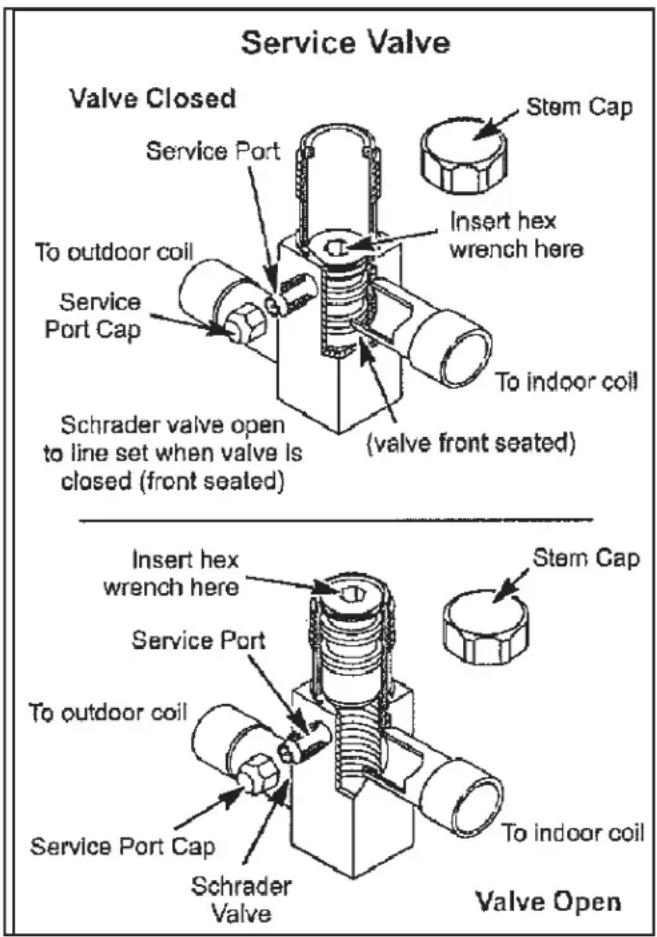
text_image
Service Valve Valve Closed Service Port To outdoor coil Service Port Cap Schrader valve open to line set when valve is closed (front sealed) Stem Cap Insert hex wrench here To indoor coil (valve front seated) Schrader valve Insert hex wrench here Service Port To outdoor coil Service Port Cap Schrader Valve Stem Cap To indoor coil Valve OpenFigure 24.
To Access the Schrader Port:
- Remove the service port cap with an adjustable wrench.
- Connect gauge to the service port.
- When testing is completed, replace service port cap. Tighten finger tight, then an additional 1/6 turn.
INSTALLATION INSTRUCTIONS
Start-Up (Cont.)
Liquid and Suction Line Service Valves (Cont)
To Open Liquid or Suction Line Service Valve:
- Remove stem cap with an adjustable wrench.
- Use service wrench with a hex-head extension to back the stem out counterclockwise as far as it will go. Use a 3/16" hex head extension for liquid line service valves and a 5/16" extension for suction line service valves.
- Replace the stem cap. Tighten finger tight, then tighten an additional 1/6 turn.
To Close Liquid or Suction Line Service Valve:
- Remove the stem cap with an adjustable wrench.
- Use a service wrench with a hex-head extension to turn the stem clockwise to seat the valve. Tighten firmly.
- Replace the stem cap. Tighten finger tight, then tighten an additional 1/6 turn.
Suction Line (Ball Type) Service Valve
Suction line (ball type) service valves function the same way as the other valves; the difference is in the construction (see Figure 25).
The ball valve is equipped with a service port with a factory-installed Schrader valve. A service port cap protects the Schrader valve from contamination and serves as the primary seal.
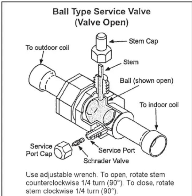
text_image
Ball Type Service Valve (Valve Open) Stem Cap Stem To outdoor coil Ball (shown open) To indoor coil Service Port Cap Service Port Schrader Valve Use adjustable wrench. To open, rotate stem counterclockwise 1/4 turn (90°). To close, rotate stem clockwise 1/4 turn (90°).Figure 25.
MAINTENANCE
Regular Maintenance Requirements
Your system should be regularly inspected by a qualified service technician. These regular visits may include (among other things) checks for:
- Motor operation
- Ductwork air leaks
- Coil & drain pan cleanliness (indoor & outdoor)
• Electrical component operation & wiring check
• Proper refrigerant level & refrigerant leaks - Proper airflow
- Drainage of condensate
• Air filter(s) performance - Blower wheel alignment, balance & cleaning
• Primary & secondary drain line cleanliness
• Proper defrost operation (heat pumps)
Air Filter
Inspect air filters at least monthly and replace or clean as required. Disposable filters should be replaced. Washable filters may be cleaned by soaking in mild detergent and rinsing with cold water. Allow filter to dry before reinstalling. Replace filters with the arrows pointing in the direction of airflow. Dirty filters are the most common cause of poor heating / cooling performance and compressor failures.
Indoor Coil
If the system has been operated with a clean filter in place, it should require minimal cleaning. If cleaning is needed, call your dealer for service.
Condensate Drain
During cooling season check at least monthly for free flow of drainage and clean if necessary.
Condenser Coils
Grass cuttings, leaves, dirt, dust, lint from clothes dryers, and foliage from trees can be drawn into coils by movement of the air. Clogged condenser coils will lower the efficiency of your unit and could cause damage to the condenser.
Periodically, debris should be brushed from the condenser coils. Use a soft bristle brush with light pressure only. DO NOT damage or bend condenser coil fins. Damaged or bent fins may affect unit operation.
WARNING
SHARP OBJECT HAZARD!
Condenser coils have sharp edges. Wear adequate body protection on body extremities (e.g. gloves).
FAILURE TO FOLLOW THIS WARNING COULD RESULT IN BODILY INJURY.
Painted Surfaces
For maximum protection of the unit's finish, a good grade of automobile wax should be applied every year. In geographical areas where water has a high concentration of minerals (calcium, iron, sulfur, etc.), it is recommended that lawn sprinklers not be allowed to spray the unit. In such applications, the sprinklers should be directed away from the unit. Failure to follow this precaution may result in premature deterioration of the unit finish and metal components.
In sea coast areas, special maintenance is required due to the corrosive atmosphere provided by the high salt concentration in ocean mists and the air. Periodic washing of all exposed surfaces and coil will add life to your unit. Please consult your installing dealer for proper procedures in your geographic area.
HOMEOWNER INFORMATION
WARNING
Turn OFF electric power to unit before performing any maintenance or removing panels or doors.
FAILURE TO DO SO COULD RESULT IN BODILY INJURY OR DEATH.
Heat Pump Operation
Your new heat pump has several characteristics that you should be aware of:
- Heat pumps satisfy heating demand by delivering large amounts of warm air into the living space. This is quite different from gas-or oil-fired furnaces or an electric furnace which deliver lower volumes of considerably hotter air to heat the space.
- Do not be alarmed if you notice frost on the outdoor coil in the winter months. Frost may develop on the outdoor coil during the heating cycle when temperatures are below 45°F. An electronic control activates a defrost cycle lasting 5 to 15 minutes at preset intervals to clear the outdoor coil of the frost.
- During the defrost cycle, you may notice steam rising from the outdoor unit. This is a normal occurrence. The thermostat may engage auxiliary heat during the defrost cycle to satisfy a heating demand; however, the unit will run to normal operation at the conclusion of the defrost cycle. NTamination and serves as the primary seal.
In case of extended power outage:
If the outdoor temperature is below 50^ F and power to your outdoor unit has been interrupted for one hour or longer, observe the following when restoring power to your heat pump system.
- Set the room thermostat selector to the “Emergency Heat” setting to obtain temporary heat for a minimum of 6 hours. This will allow system refrigerant pressures and temperatures enough time to return to a stabilized condition.
- In Emergency Heat mode, all heating demand is satisfied by auxiliary heat; heat pump operation is locked out. After a 6 hour “warm-up” period, the thermostat can then be switched to the “Heat” setting and normal heat pump operation may resume.
Thermostat Operation
The wall-mounted thermostat controls your heat pump. The thermostat is available in various configurations from different manufacturers. The information below is typical for most thermostats. Ask your dealer for specific information regarding the model of thermostat installed.
Fan Switch
In AUTO or INT (intermittent) mode, the blower operates only when the thermostat calls for heating or cooling. This mode is generally preferred when humidity control is a priority.
The ON or CONT mode provides continuous indoor blower operation, regardless of whether the compressor or auxiliary heat are operating. This mode is required when constant air circulation or filtering is desired.
On models without a fan selection switch, the fan will cycle with the outdoor unit.
System Switch
Set the system switch for heating, cooling or auto operation. The auto mode allows the heat pump to automatically switch from heating mode to cooling mode to maintain predetermined comfort settings. Many heat pump thermostats are also equipped with an emergency heat mode which locks out heat pump operation and provides temporary heat supplied by the auxiliary heat.
Indicating Light
Most heat pump thermostats have an amber light which indicates when the heat pump is operating in the emergency heat mode.
Temperature Indicator
The temperature indicator displays the actual room temperature.
Programmable Thermostats
Your system may be controlled by a programmable thermostat. These thermostats provide the added feature of programmable time-of-day set points for both heating and cooling. Refer to the user's information manual provided with your particular thermostat for operation details.
HOMEOWNER INFORMATION
Important System Information
- Your system should never be operated without a clean air filter properly installed.
- Return air and supply air registers should be free from restrictions or obstructions to allow full flow of air.
IF YOUR SYSTEM DOES NOT WORK, BEFORE REQUESTING A SERVICE CALL:
- Ensure thermostat is set below (cooling) or above (heating) room temperature and that the system lever is in the "COOL", "HEAT" or "AUTO" position.
-
Inspect your return air filter: If it is dirty, your heat pump may not function properly.
-
Check indoor and outdoor disconnect switches. Confirm circuit breakers are ON or that fuses have not blown. Reset breakers/replace fuses as necessary.
- Inspect the outdoor unit for clogged condenser coils, (grass cuttings, leaves, dirt, dust or lint). Ensure that branches, twigs or other debris are not obstructing the condenser fan.
IF YOUR SYSTEM STILL DOES NOT OPERATE, CONTACT YOUR SERVICING DEALER.
Be sure to describe the problem, and have the model and serial numbers of the equipment available.
If warranty replacement parts are required, the warranty must be processed through a qualified distribution location.
| Start-Up and Performance Checklist | |
| Customer:____ Address:____Indoor Unit Model:____ Serial:____Outdoor Unit Model:____ Serial:____Notes:____ | |
| Start-Up ChecksRefrigerant Type:____Rated Load Amps:____ Actual Amps:____ Rated Volts:____ Actual Volts:____Condenser Fan Full Load Amps:____ Actual Amps:____Cooling ModeSuction Pressure:____ Liquid Pressure:____Supply Air Temperature:____ Ambient Temperature:____ Return Air Temperature:____ | |
| System Refrigerant Charge (Refer to manufacturer's information on unit or installation instructions for required subcooling and approach temperatures.) | |
| Subcooling:Saturated Condensing Temperature (A)minus Outdoor Air Temperature (B) | A - B = Subcooling |
| Approach:Liquid Line Temperature (A)minus Outdoor Air Temperature (B) | A - B = Approach |
| Indoor Coil Temperature Drop (18 to 22°F):Return Air Temperature (A)minus Supply Air Temperature (B) | A - B = Coil Temp Drop |
HAIER DUCTED HVAC LIMITED WARRANTY
Haierappliances.com
Please save your receipt showing the date of original purchase and the date of installation.
For the product models listed on Attachment 1 (the "Product"), this Standard Limited Warranty is provided to the Original Owner of the Product:
| For The Period Of: GE Appliances Will Replace: | |
| 5 year Limited Parts WarrantyFrom the date of the original purchase | If any parts should prove to be defective due to improper workmanship and/or material for a period of five (5) years from the date of installation, Haier will replace any defective parts without charge for the part. Parts used for replacement may be new or refurbished parts, determined at Haier's sole discretion, and provided to your licensed HVAC technician installer. |
| 10 Year Registered Limited Parts WarrantyFrom the date of the original purchase(ONLINE REGISTRATION REQUIRED at Haierappliances.com)MUST BE A RESIDENTIAL SINGLE- FAMILY HOME | If any of the parts should prove defective due to improper workmanship and/or material for a period of ten (10) years from the date of installation, Haier will replace any defective parts without charge for the part. The replacement part is warranted for the remainder of the original ten (10) year warranty period. Parts used for replacement may be new or refurbished parts, determined at Haier's sole discretion, and provided to your licensed HVAC technician installer. This Registered Limited Parts Warranty requires online registration within sixty (60) days from the original date of installation or occupancy.NON-RESIDENTIAL/ COMMERCIAL APPLICATIONS ARE NOT ELIGIBLE FOR THIS REGISTERED LIMITED PARTS WARRANTY. |
LABOR NOT COVERED:
These limited warranties DO NOT include labor, or any other costs incurred for service, maintenance, repair, removing, replacing, installing, complying with local building or electrical codes, shipping or handling, replacement of the system, compressors or other parts.
EXCLUDED COMPONENTS:
The following components are not covered by this warranty: cabinets, cabinet pieces, air filters, driers, refrigerant, refrigerant line sets, belts, wiring, fuses, oil nozzles, unit accessories and any parts not affecting unit operation.
WHAT IS THE DATE OF PURCHASE:
The “Date of Purchase” is the date that the original installation is complete, and all product start-up procedures have been properly completed and verified by the installer’s invoice. If the installation date cannot be verified, then the Date of Purchase will be sixty (60) days after the manufacture date, as determined by the Product’s serial number. You should keep and be able to provide your original sales receipt from the installer as proof of the Date of Purchase. For new construction, the Date of Purchase will be the date of purchase of the residence by the Owner from the builder.
WHO IS COVERED:
Owner occupied: The “Original Owner” means the original owner (and his or her spouse) of a residential single family where the Product was originally installed.
Non-Owner occupied: The “Non-Owner occupied” is defined as a) single family or multi-family residential buildings that are not Owner Occupied, or b) light commercial applications, (such as office buildings, retail establishments, hotels/motels).
For Non-owner occupied: This limited warranty requires that the Product be installed and maintained annually by a licensed HVAC technician (proof of annual maintenance is required).
HOW CAN YOU GET SERVICE:
Contact your licensed HVAC technician installer. All installation and service must be performed by a licensed HVAC technician. Failure to use a licensed HVAC technician for installation of this Product voids all warranty on this Product.
HAIER DUCTED HVAC LIMITED WARRANTY
WHAT HAIER WILL NOT COVER:
- Improper service or installation.
- Damage in shipping.
- Defects other than manufacturing defects (i.e., other than workmanship or materials).
- Damage from misuse, abuse, accident, alteration, lack of proper care and/or regular maintenance.
- Damage resulting from floods, fires, wind, lightning, accidents or similar conditions.
- Product that was not installed or serviced by a licensed HVAC technician.
• Labor and related services for repair or installation of the Product. - A product purchased from an unauthorized online retailer.
- Damage as a result of subjecting Product to an atmosphere with corrosives or high levels of particulates (such as soot, aerosols, fumes, grease).
- Modification, change or alteration of the equipment, except as directed in writing by Haier.
- Use of contaminated or refrigerant not compatible with the unit.
-
Operation with system components (indoor unit, outdoor unit, and refrigerant control devices) which are not an AHRI match or meet the specifications recommended by Haier.
-
A Product sold and/or installed outside of the 50 United States, the District of Columbia, or Canada.
- Batteries for the controller and other accessories provided with the Product for installation (e.g., plastic hose).
- Normal maintenance, such as cleaning of coils, cleaning filters, and lubrication.
- For Product installed in non-owner occupied applications, Product that has not been maintained annually by a licensed HVAC technician (proof required).
- Damage caused by a used or unapproved component or part by Haier (e.g., a used and/or unapproved condenser / air handler).
- Component or parts not provided by Haier.
- Product that has been moved from its original installation to a new residence or building.
- Accident, or neglect or unreasonable use or operation of the equipment including operation of electrical equipment at voltages other than the range specified on the unit nameplate (includes damages caused by brownouts).
- Damage to the product caused by accident, fire, floods or acts of God.
- Incidental or consequential damage caused by possible defects with this product.
LEGAL RIGHTS:
Some states and provinces do not allow warranty terms to be subject to registration. In those states and provinces, the 10 year Registered Limited Parts Warranty applies. In addition, if allowed by the law of the state or province where the Product is installed, the subsequent owners of the residence or building may have additional rights or longer warranty terms.
REGISTERED LIMITED PARTS WARRANTY COVERAGE REQUIREMENTS:
• The unit is a Haier branded unit.
- The unit is installed in a residential application.
• The unit is properly registered at Haierappliances.com within 60 days after the original date of installation or occupancy.
- The unit is part of a complete AHRI matched system and installed by a state certified or licensed contractor in accordance with the unit installation, operation, and maintenance instructions provided with the unit.
- Indoor and outdoor ducted units are covered only when they are branded Haier and are purchased and installed as a system along with a qualifying unit. (Third party coils are not covered).
• Installation is in compliance with applicable laws, regulations, codes, and ordinances.
- Unit was not ordered via the internet. Proof of purchase may be required.
HAIER DUCTED HVAC LIMITED WARRANTY
EXCLUSION OF IMPLIED WARRANTIES:
EXCEPT TO THE EXTENT PROHIBITED BY APPLICABLE LAW, THIS LIMITED WARRANTY IS EXCLUSIVE AND GIVEN IN LIEU OF ALL OTHER WARRANTIES, EXPRESS OR IMPLIED, INCLUDING BUT NOT LIMITED TO ANY IMPLIED WARRANTY OF MERCHANTABILITY AND FITNESS FOR A PARTICULAR PURPOSE.
UNDER NO CIRCUMSTANCES SHALL HAIER BE LIABLE FOR ANY INDIRECT, INCIDENTAL, SPECIAL OR CONSEQUENTIAL DAMAGES INCLUDING, WITHOUT LIMITATION, LOST GOODWILL, LOST REVENUE OR PROFITS, WORK STOPPAGE, SYSTEM FAILURE, IMPAIRMENT OF OR DAMAGE TO OTHER EQUIPMENT OR GOODS, COST OF REMOVAL AND REINSTALLATION OF THE SYSTEM, LOSS OF USE, INJURY TO PERSONS OR PROPERTY ARISING OUT OF OR RELATED TO THE SYSTEM. HAIER'S TOTAL LIABILITY, IF ANY, UNDER THIS LIMITED WARRANTY SHALL NOT EXCEED THE INVOICE VALUE PAID BY THE CUSTOMER FOR THE SYSTEM WHICH IS THE SUBJECT OF A CLAIM OR DISPUTE.
SOME STATES DONOT ALLOW THE EXCLUSION OR LIMITATION OF INCIDENTAL OR CONSEQUENTIAL DAMAGES, OR ALLOW DISCLAIMERS OF IMPLIED WARRANTIES, SO THE ABOVE LIMITATIONS OR EXCLUSIONS MAY NOT APPLY TO THE CUSTOMER. THIS LIMITED WARRANTY GIVES THE CUSTOMER SPECIFIC LEGAL RIGHTS. CUSTOMERS MAY ALSO HAVE OTHER RIGHTS THAT VARY FROM STATE TO STATE.
The remedy provided in this warranty is exclusive and is granted in lieu of all other remedies. This warranty does not cover incidental or consequential damages. Some states and provinces do not allow the exclusion of incidental or consequential damages, so this limitation may not apply to you. Some states and provinces do not allow limitations on how long an implied warranty lasts, so this limitation may not apply to you. This warranty gives you specific legal rights and you may also have other rights which vary by state and province. This warranty covers Products within the 50 United States, the District of Columbia and Canada.
This warranty is provided by:
GE Appliances, a Haier company
Louisville, KY 40225
For US Customers: This limited warranty is extended to the original purchaser for products purchased for home use within the USA. In Alaska and Hawaii, the limited warranty does not include the costs of shipping units.
Some states do not allow the exclusion or limitation of incidental or consequential damages. This warranty gives you specific legal rights, and you may also have other rights which vary from state to state. To know what your legal rights are, consult your local or state consumer affairs office or your state's Attorney General.
GE Appliances, a Haier company
Louisville, KY 40225
ATTACHMENT 1:
The “Product” is defined as Haier brand Ducted Unitary Units. The “Product” contains 2 sub-categories of goods: “Indoor and Outdoor Products” and “Selected Installation Products,” which are further defined below: “Indoor and Outdoor Products” can further be identified by the following model number descriptions: 1U*, NAM*, NC*, NF* & NP*
RECORD KEEPING
Thank you for purchasing this Haier product. This installation manual will help you get the best performance from your new heat pump.
For future reference, record the model and serial number located on the label on the side of your air conditioner/heat pump, and the date of purchase. Staple your proof of purchase to this manual to aid in obtaining warranty service if needed.
To register your new Haier Ducted System, go to geappliancesairandwater.com and input the model/serial number information on this page.
Model number
Serial number
Date of purchase
text_image
Gabarit d'évasement A = ~1/16" (1.6mm) Pipe A = AFigure 10.
natural_image
Mechanical clamp device with rotating arms and base plates (no text or symbols)Figure 11.
INSTALLATION D'UN BULBE SENSIBLE
4. ÉVACUATION DU SYSTÈME (suite)
flowchart
graph TD
    A["Thermostat"] -->|W1 W2 G O R C Y| B["Defrost Tempering Kit"]
    B -->|W1 O R C Y1 Y2| C["Heat Pump"]
    C --> D["Optional N.C. CONDENSATE FLOAT SWITCH"]
    D --> E["TSTAT"]
    E --> F["SW2 SENSOR #1"]
    E --> G["SW1"]
    F --> H["RDS Field Kit - 24 Volt Cat # (27A05)"]
    G --> H
    H --> I["INDOOR"]
    I --> J["Single Stage Variable Speed Gas Furnace"]
    style A fill:#f9f,stroke:#333
    style J fill:#bbf,stroke:#333
    note right of H: RDS Field Kit - 24 Volt
    note right of I: ZONING ALARM
    note left of H: ZONING NO COM NC NO COM NC
    note right of I: THERmostat / Outdoor Unit Terminal Block (BLACK)
    note right of J: Indoor Unit Terminal Block (BLUE)
    note_right_of_K["A Dual Fuel Thermostat is Required for Dual Fuel Application & will need to be programmed for dual"]
    note_right_of_L["Defrost Tempering Kit is required for Dual Fuel Application"]
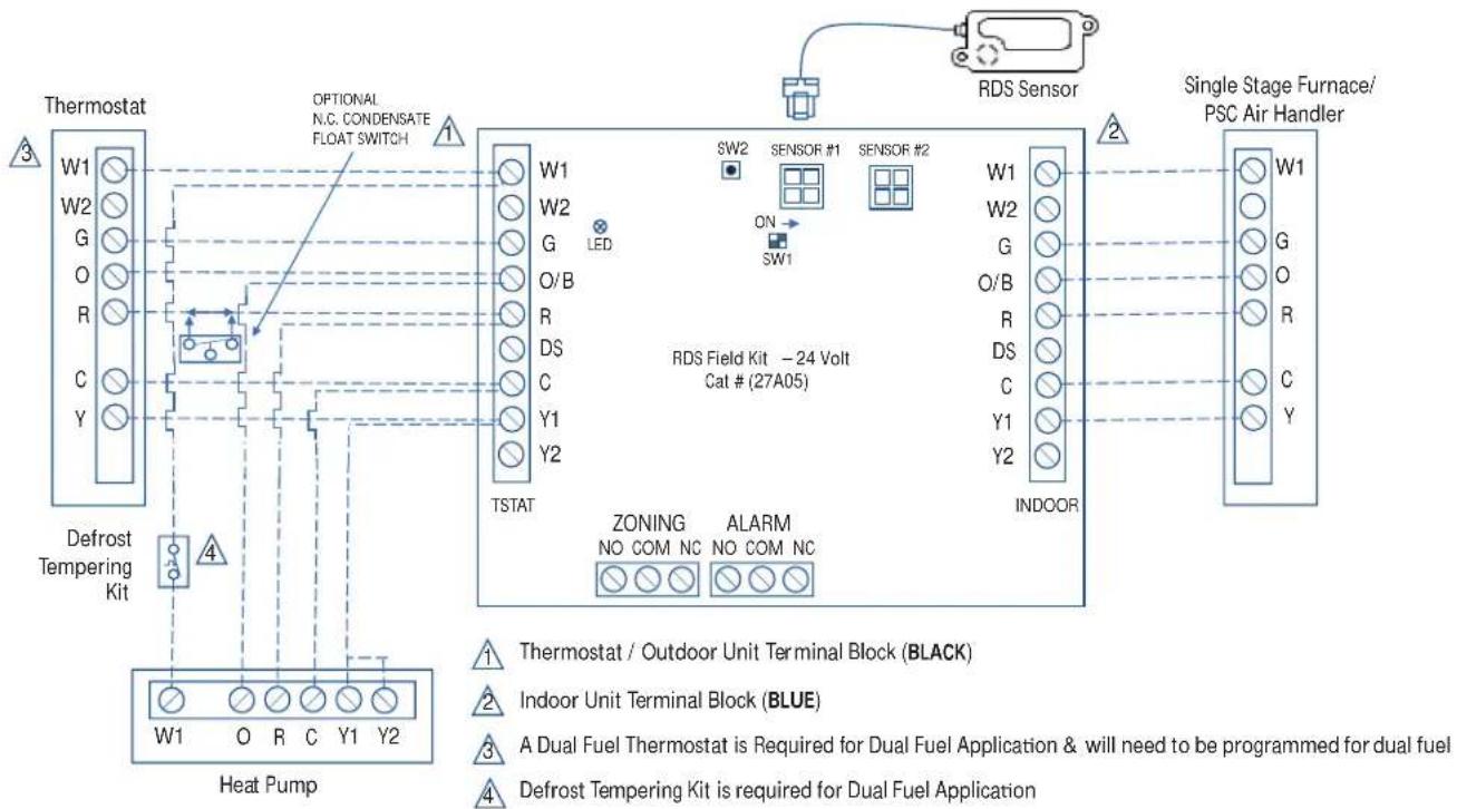
flowchart
graph TD
    A["Thermostat"] -->|W1 W2 G O R C Y| B["Defrost Tempering Kit"]
    B --> C["Heat Pump"]
    C --> D["Optional N.C. CONDENSATE FLOAT SWITCH"]
    D --> E["W1 W2 G O/B R DS C Y1 Y2 TSTAT"]
    E --> F["RDS Field Kit - 24 Volt Cat # (27A05)"]
    F --> G["SW2 SENSOR #1 SENSOR #2"]
    G --> H["INDOOR"]
    H --> I["Single Stage Furnace/PSC Air Handler"]
    style A fill:#f9f,stroke:#333
    style B fill:#ccf,stroke:#333
    style C fill:#cfc,stroke:#333
    style D fill:#fcc,stroke:#333
    style E fill:#cff,stroke:#333
    style F fill:#ffc,stroke:#333
    style G fill:#ffc,stroke:#333
    style H fill:#ffc,stroke:#333
    style I fill:#ffc,stroke:#333
INSTRUCTIONS D'INSTALLATION
flowchart
graph TD
    A["Thermostat"] --> B["Defaulting Kit"]
    B --> C["Heat Pump"]
    C --> D["Defrost Tempering Kit"]
    D --> E["Optional N.C. CONDENSATE FLOAT SWITCH"]
    E --> F["TSTAT"]
    F --> G["RDS Field Kit - 24 Volt Cat # (27A05)"]
    G --> H["Indoor Unit Terminal Block (BLUE)"]
    H --> I["A Dual Fuel Thermostat is Required for Dual Fuel Application & will need to be programmed for dual fuel"]
    I --> J["Defrost Tempering Kit is required for Dual Fuel Application"]
    J --> K["Thermostat / Outdoor Unit Terminal Block (BLACK)"]
    K --> L["SW2 Sensor #1 Sensor #2"]
    L --> M["ON SW1"]
    M --> N["Indoor Unit Terminal Block (BLUE)"]
    N --> O["W1 W2 G O R Y1 Y2"]
    style A fill:#f9f,stroke:#333
    style B fill:#ccf,stroke:#333
    style C fill:#cfc,stroke:#333
    style D fill:#fcc,stroke:#333
    style E fill:#ffc,stroke:#333
    style F fill:#fcc,stroke:#333
    style G fill:#cff,stroke:#333
    style H fill:#ffc,stroke:#333
    style I fill:#cfc,stroke:#333
    style J fill:#fcc,stroke:#333
    style K fill:#ffc,stroke:#333
    style L fill:#fcc,stroke:#333
    style M fill:#ffc,stroke:#333
    style N fill:#cfc,stroke:#333
    style O fill:#fcc,stroke:#333
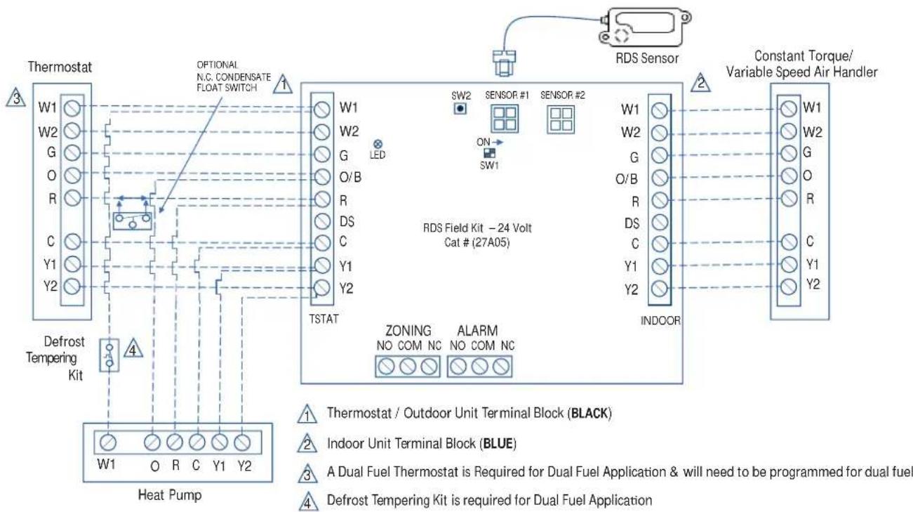
flowchart
graph TD
    A["Thermostat"] -->|W1 W2 G O R C Y1 Y2 Defrost Tempering Kit| B["Defrost Tempering Kit"]
    B --> C["Heat Pump"]
    C --> D["Optional N.C. CONDENSATE FLOAT SWITCH"]
    D --> E["W1 W2 G O/B R DS C Y1 Y2 TSTAT"]
    E --> F["SW2 SENSOR. #1 SENSOR. #2"]
    F --> G["ON SW1"]
    G --> H["RDS Field Kit - 24 Volt Cat # (27A05)"]
    H --> I["ZONING NO COM NC ALARM NO COM NC"]
    I --> J["Constant Torque/Variable Speed Air Handler"]
    J --> K["Indoor Unit Terminal Block (BLUE)"]
    K --> L["Thermostat / Outdoor Unit Terminal Block (BLACK)"]
    K --> M["A Dual Fuel Thermostat is Required for Dual Fuel Application & will need to be programmed for dual fuel"]
    K --> N["Defrost Tempering Kit is required for Dual Fuel Application"]
INSTRUCTIONS D'INSTALLATION
text_image
Base pan heater Crankcase heater 4WV Y/G CN1 CON1 CON2 CN9 G CN9 CN7 W DEF CN6 Y CN5 L2 B W L1 BL Power supply R M U V W R M U V W R M U V W R M U V W R M U V W R M U V W R M U V W R M U V W R M U V W R M U V W R M U V S W5 S W7 S W6 CN26 CN1 CN20 CN25 CN24 CN13 CN14 CN15 R PD LP HP TC B45 E.E.V. E.E.V. DC FAN MOTORLP/HP: Low/High Pressure Switch
Tc: Condensing Temp. Sensor
Ts: Condensing Suction Temp. Sensor
Ta: Ambient Temp.Sensor
Td: Compressor Discharge Temp. Sensor
Te: Condensing Out Temp.Sensor
PD: High Pressure Sensor
4WV: 4 Way Valve
RAST TERMINALS FOR
THERMOSTAT WIRING
CONNECTION
DISPLAY BOARD
SW5 function is shown in Table 7
SW7 centralized controller address selection (reserved function),
SW6 test dip (do not move unless tested)
text_image
If the thermostat adopts a single-stage cooling/heating system, only connect Y2. If the thermostat adopts a two-stage cooling/heating system, connect Y1 and Y2 respectively. For DIP switches definition details, please refer to the service manual. OR: Orange B: Black BL: Blue R: Red Y/G: Yellow/Green W: White Y: Yellow BW: Blue/white Power supply Cranixcase heater Base pan heater 4WV G CN28 CN4 B CN5 W Y DEFR CN22 T6.3A 250V B W CN2 CN34 Main control Board BL R R SW5 SW7 SW6 ON13 ON12 R R CN14 BL CN25 R CN23 W CN8 Tc TsTa Td Te PD E.E.V CN9 CN15 CN26 To RJ45 device DC FAN MOTOR2(UP) M Inverter Board1 DCFAN1 DC FAN INverter Board2 DC FAN MOTOR2(UP) 0150571173GE Appliances, a Haier company
Louisville, KY 40225
Warrantor: GE Appliances, a Haier company
Louisville, KY 40225


