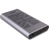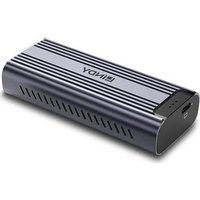
43394 - External hard drive Lindy - Free user manual and instructions
Find the device manual for free 43394 Lindy in PDF.


User questions about 43394 Lindy
0 question about this device. Answer the ones you know or ask your own.
Ask a new question about this device
Download the instructions for your External hard drive in PDF format for free! Find your manual 43394 - Lindy and take your electronic device back in hand. On this page are published all the documents necessary for the use of your device. 43394 by Lindy.
USER MANUAL 43394 Lindy
natural_image
Exterior view of a dark, modern LINDY brand electronic device with visible grille and ventilation slots (no text or symbols beyond branding)No. 43394
lindy.com
Introduction
Thank you for purchasing the Lindy USB4 NVMe M.2 SSD Enclosure. This product has been designed to provide trouble free, reliable operation. It benefits from both a Lindy 2 year warranty and free lifetime technical support. To ensure correct use, please read this manual carefully and retain it for future reference.
The Lindy USB4 NVMe M.2 SSD Enclosure allows the user to install a PCIe/NVMe based M.2 SSD as an external drive to USB4 or Thunderbolt 3/4 hosts like laptops or PCs. Support for the USB4 standard guarantees extremely fast data transfer rates up to 40Gbps.*
This Lindy enclosure is compatible with PCIe/NVMe based M.2 SSDs with M key or B + M key in 42, 60 and 80mm lengths. The Aluminium housing with Aluminium heatsink ensures excellent heat dissipation and a suitable operating temperature. The tool-free design makes installation very easy.
* Please note that 40Gbps full support is only possible with a USB4, Thunderbolt 3 or 4 host controller.
Package Contents
■ USB4 M.2 NVMe SSD Enclosure
■ 15cm USB4 40Gbps FPC Flat cable
- Aluminium Heatsink Kit (Aluminium Heatsink, Metal Bracket, 2x Silicone Thermal Pad, 4x Screws)
■ 1x Mini Screwdriver
- 2x Screw + Nut
- Lindy manual
Specification
■ USB4 (40Gbps) standard
■ Supports PCIe 4.0 x4 M.2 NVMe SSD
■ Supports 42mm (2242), 60mm (2260) and 80mm (2280) M.2 NGFF form factors with M key and B + M key
Chipset: ASM2464PD
■ UASP & TRIM support
■ Durable Aluminium casing
- Plug and Play, USB Bus powered
- LED status indicator: solid blue for successful connection, flickering for data transfer
- Operating temperature: 0°C - 45°C (32°F - 113°F)
■ Storage temperature: -10^ - 70^ ( -14^ - 158^ )
■ Humidity: 10 - 85 % RH (non-condensing)
Overview
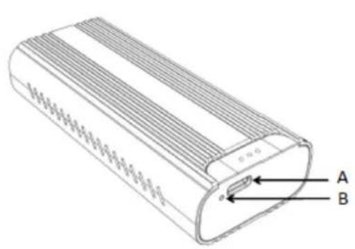
text_image
A B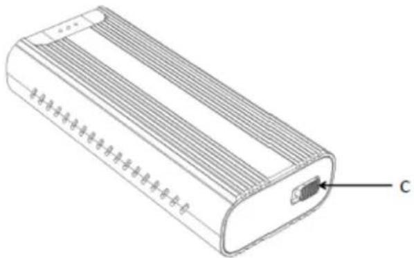
text_image
CA: Upstream Port (USB Type C female)
B: LED Status Indicator
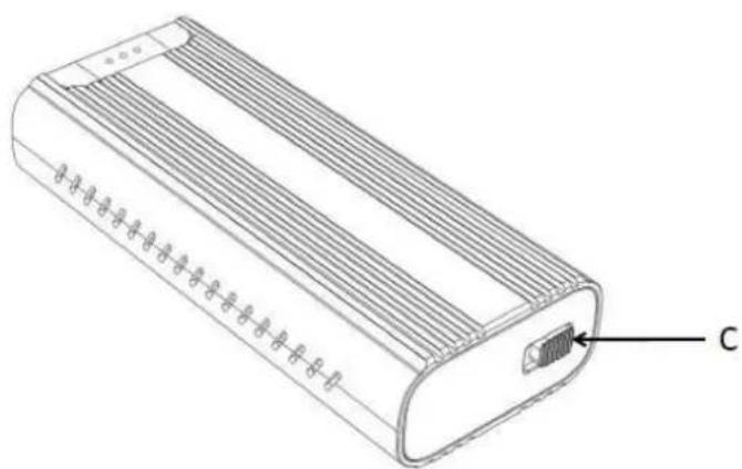
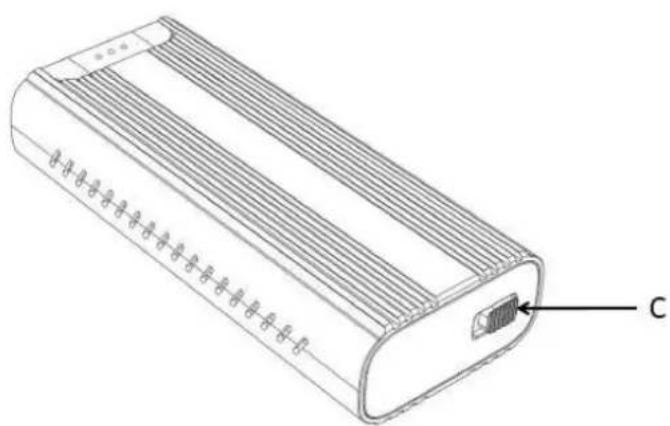
C: Secure Lock
Installation & Operation
Please follow the steps below for installation:
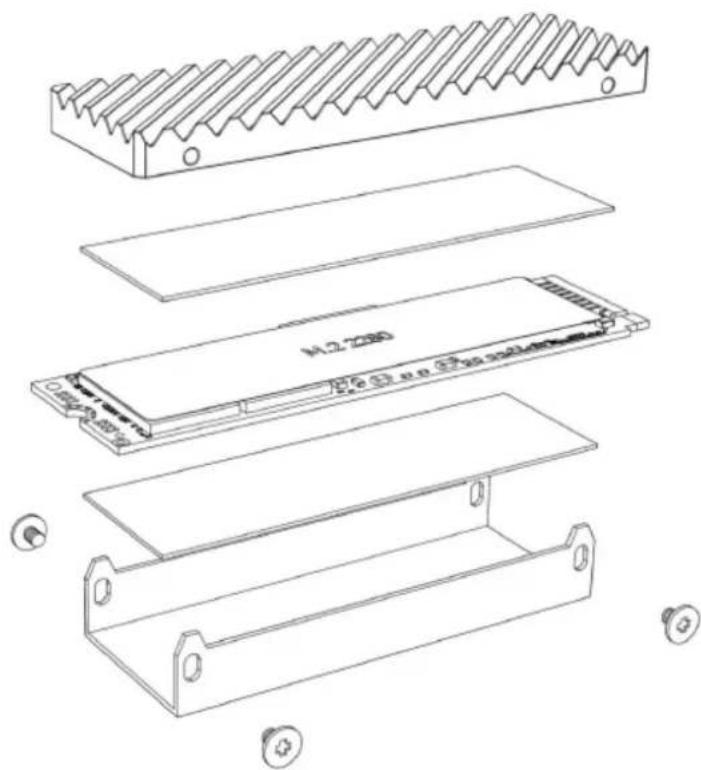
Aluminium Heatsink Installation
- Remove the surface layer of the thicker silicone thermal pad.
- Attach the silicone thermal pad to the top of the M.2 SSD.
- Attach the Aluminium heatsink to the silicone thermal pad.
- Remove the surface layer of the thinner silicone thermal pad.
- Attach the silicone thermal pad to the bottom of the M.2 SSD.
- Attach the M.2 SSD into the Metal Bracket.
- Use the Mini Screwdriver to lock the heatsink and metal bracket.
text_image
Technical diagram of an electronic component with labeled parts and mounting holesM.2 SSD Installation
natural_image
Technical line drawing of a rectangular electronic device with internal components and labeled component 'C' (no text or symbols beyond label)Push the switch C to the left and press the inner frame backwards to open the enclosure.
natural_image
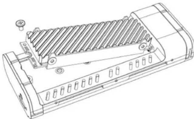
Technical line drawing of a mechanical component with ribbed internal structure and mounting holes (no text or symbols)Insert the M.2 SSD* diagonally into the NVMe slot and gently press down the M.2 SSD.
natural_image
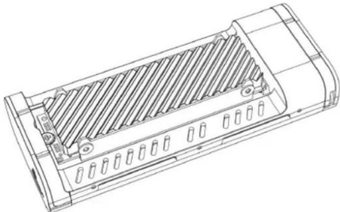
Technical line drawing of a rectangular electronic device with internal grating and mounting holes (no text or symbols)Use the Mini Screwdriver to lock the M.2 SSD.
Finally use the included USB4 Flat Cable to connect the Enclosure with your host computer. The USB4 NVMe M.2 SSD Enclosure is now ready for operation.
Please note:
-
Please be careful to prevent static electricity when using this enclosure and installing the M.2 SSD. It is recommended to put your hands on a metal object to discharge.
-
Make sure that the enclosure is powered off when you install the M.2 SSD (although it supports hot-swapping).
-
Try to move gently and do not press violently to avoid scratching the components on the motherboard of the M-2 SSD during installation.
-
The enclosure is recommended to be used on Windows 10/11, macOS 10.9 or higher for best performance.
*If you are using a new M.2 SSD, it must first be initialized, formatted and partitioned.
Einführung
natural_image
Technical line drawing of a rectangular electronic device with labeled component 'C' (no text or symbols on the body)text_image
Technical diagram of an electronic component with labeled parts and mounting holesM.2 SSD Installation
text_image
Technical diagram of a rectangular electronic device with labeled ports and internal structure, marked with letter C.natural_image
Technical line drawing of a mechanical device with heat exchanger and mounting bracket (no text or symbols)natural_image
Technical line drawing of a rectangular electronic device with internal grating and mounting holes (no text or symbols)text_image
Technical diagram of an air conditioner unit with labeled parts A and B, showing internal structure and component annotations.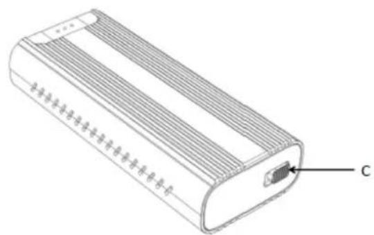
natural_image
Line drawing of a rectangular electronic device with ventilation slots and a labeled component (no text or symbols beyond label)text_image
Technical diagram of an electronic component with labeled parts and mounting holesnatural_image
Technical line drawing of a mechanical component with ribbed internal structure and mounting holes (no text or symbols)natural_image
Technical line drawing of a rectangular electronic device with internal grating and mounting holes (no text or symbols)text_image
Technical diagram of a rectangular electronic device with labeled parts A and B, showing internal structure and ventilation patterns.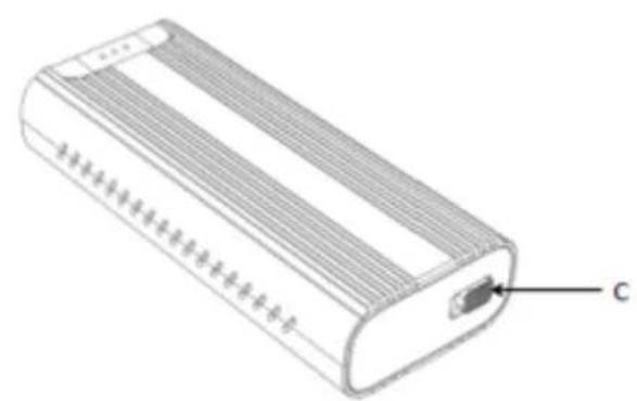
natural_image
Illustration of a rectangular electronic device with internal components and labeled component 'C' (no text or symbols beyond label)text_image
Technical diagram of an electronic component with labeled parts and mounting holesnatural_image
Technical line drawing of a rectangular electronic device with internal components and labeled component 'C' (no text or symbols beyond label)natural_image
Technical line drawing of a mechanical component with ribbed internal structure and mounting holes (no text or symbols)natural_image
Technical line drawing of a rectangular electronic device with internal grating and mounting holes (no text or symbols)text_image
Technical diagram of a cylindrical device with labeled parts A and B, showing internal structure and mounting points.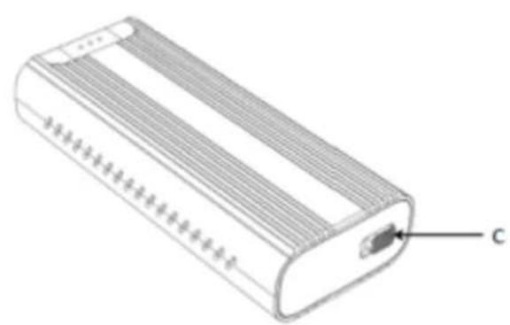
natural_image
Technical line drawing of a rectangular electronic device with a labeled component 'C' (no text or symbols on the body)natural_image
Exploded view diagram of an electronic component showing internal structure and mounting holes (no text or symbols)natural_image
Technical line drawing of a rectangular electronic device with internal structure and labeled component 'C' (no text or symbols beyond label)natural_image
Technical line drawing of a mechanical component with internal channels and mounting holes (no text or symbols)natural_image
Technical line drawing of a rectangular electronic device with internal grating and mounting holes (no text or symbols)WEEE (Waste of Electrical and Electronic Equipment), Recycling of Electronic Products
Europe, United Kingdom
In 2006 the European Union introduced regulations (WEEE) for the collection and recycling of all waste electrical and electronic equipment. It is no longer allowable to simply throw away electrical and electronic equipment. Instead, these products must enter the recycling process. Each individual EU member state, as well as the UK, has implemented the WEEE regulations into national law in slightly different ways. Please follow your national law when you want to dispose of any electrical or electronic products. More details can be obtained from your national WEEE recycling agency.
LINDY declares that this equipment complies with relevant European CE requirements.
LINDY declares that this equipment complies with relevant UKCA requirements.
FCC Certification
This equipment has been tested and found to comply with the limits for a Class B digital device, pursuant to part 15 of the FCC Rules. These limits are designed to provide reasonable protection against harmful interference in a residential installation.
You are cautioned that changes or modification not expressly approved by the party responsible for compliance could void your authority to operate the equipment.
This device complies with part 15 of the FCC Rules.
Operation is subject to the following two conditions:
-
This device may not cause harmful interference, and
-
This device must accept any interference received, including interference that may cause undesired operation.
Tested to comply with
FCC standards.
For home and office use.
No. 43394
^st Edition, January 2024
lindy.com