GK520DCZ - Compressor SCHEPPACH - Free user manual and instructions
Find the device manual for free GK520DCZ SCHEPPACH in PDF.

User questions about GK520DCZ SCHEPPACH
0 question about this device. Answer the ones you know or ask your own.
Ask a new question about this device
Download the instructions for your Compressor in PDF format for free! Find your manual GK520DCZ - SCHEPPACH and take your electronic device back in hand. On this page are published all the documents necessary for the use of your device. GK520DCZ by SCHEPPACH.
USER MANUAL GK520DCZ SCHEPPACH
natural_image
Black industrial air compressor with German text and model number 412 L/min, no visible signage or symbols beyond branding
text_image
https://www.scheppach.com/dalservice scheppachGK520DCZ
| DE | KompressorOriginalbetriebsanleitung | 6 |
| GB | CompressorTranslation of original instruction manual | 19 |
| FR | CompresseurTraduction des instructions d'origine | 30 |
text_image
Exploded view diagram of an air compressor with numbered parts and exploded views for assembly or maintenance.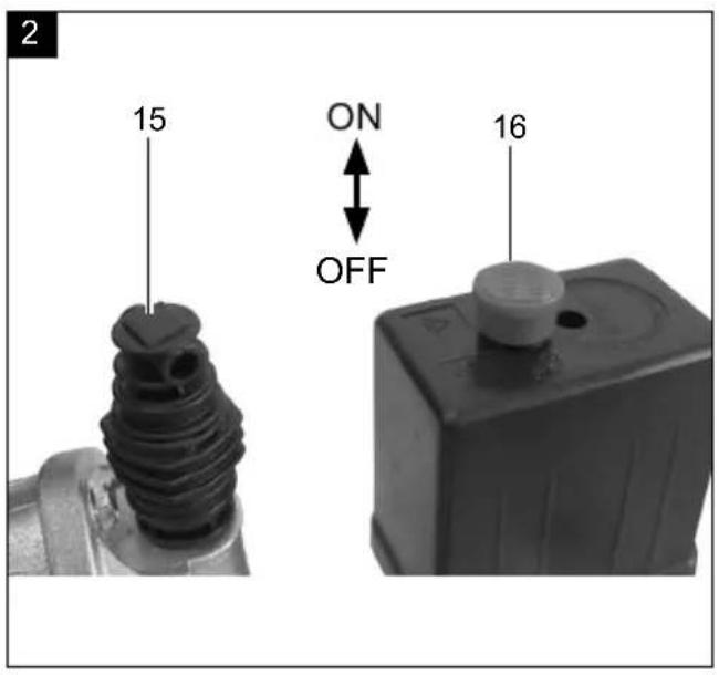
text_image
2 15 ON OFF 16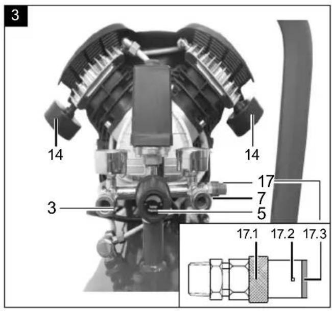
text_image
3 14 14 17 7 5 3 17.1 17.2 17.3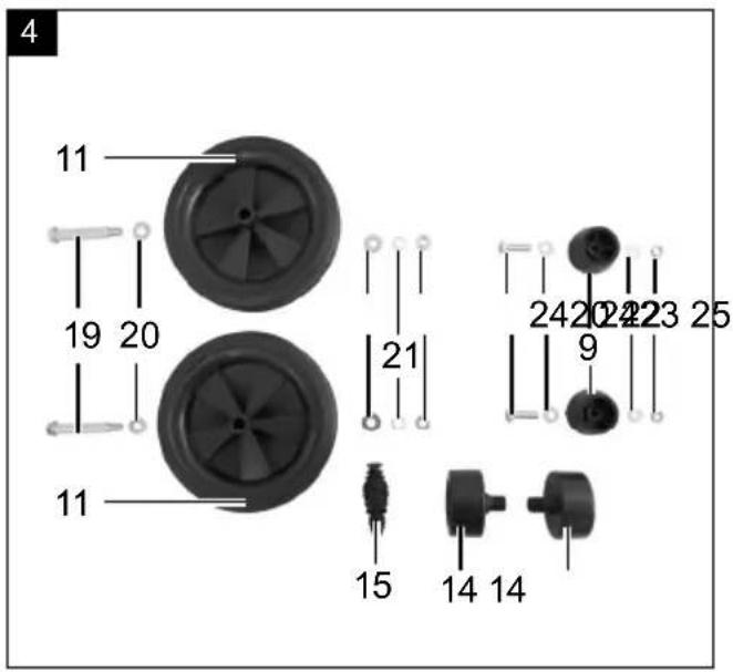
text_image
4 11 19 20 11 21 24 20 23 25 9 15 14 14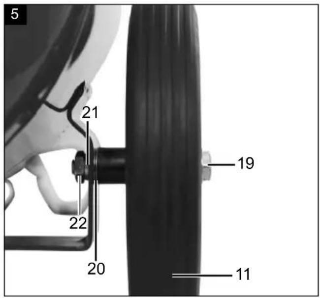
text_image
5 21 22 20 19 11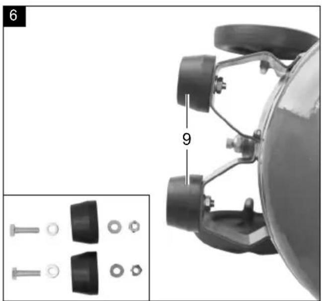
text_image
6 9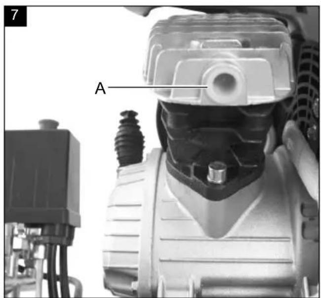
text_image
7 A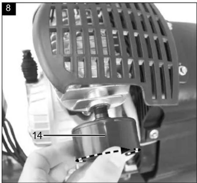
natural_image
Close-up of a hand operating a mechanical device with a grid-patterned cover and labeled component '14' (no readable text or symbols beyond label)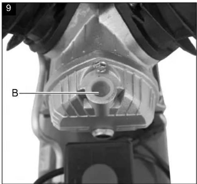
text_image
9 B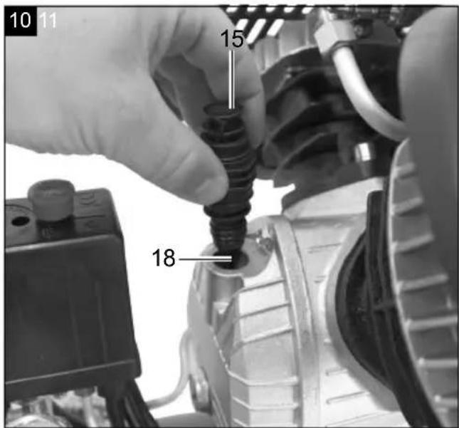
text_image
10 11 15 18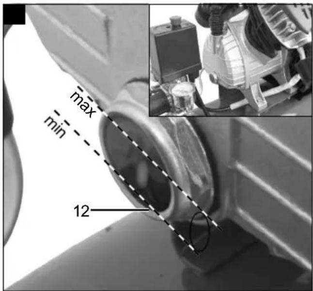
text_image
max min 12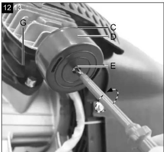
text_image
12 13 G C D E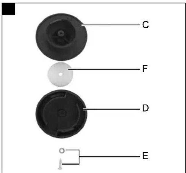
text_image
C F D EGünzburger Straße 69
D-89335 Ichenhausen
Verehrter Kunde,
Homepage: https://www.scheppach.com/de/service
text_image
https://www.scheppach.com/de/service scheppachExplanation of the symbols on the product
Symbols are used in this manual to draw your attention to potential hazards. The safety symbols and the accompanying explanations must be fully understood. The warnings themselves will not rectify a hazard and cannot replace proper accident prevention measures.
 | Read the operating and safety instructions before start-up and follow them! |
 | Wear hearing protection! |
 | Wear respiratory protection! |
 | Wear protective goggles to protect your eyes. Sparks created during work or fragments, chippings and dust ejected by the device can case sight loss. |
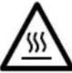 | Warning against hot parts! |
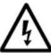 | Warning against electrical voltage! |
 | Warning! The equipment is remote-controlled and may start-up without warning. |
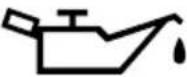 | Attention! Prior to initial commissioning, check the oil level and replace the oil sealing plug! |
 | Do not expose the machine to rain. The device may only be stationed, stored and operated in dry ambient conditions. |
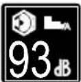 | Sound power level specified in dB |
 | The product complies with the applicable European directives. |
Table of contents: Page:
- Introduction....21
- Device description (Fig. 1 - 14)....21
- Scope of delivery 21
- Proper use....22
- Safety information....22
- Technical data....24
- Before commissioning 25
- Attachment and operation 25
- Electrical connection 26
- Cleaning, maintenance and storage....26
- Disposal and recycling....28
- Troubleshooting 29
- Declaration of conformity 43
1. Introduction
Manufacturer:
Scheppach GmbH
Günzburger Straße 69
D-89335 Ichenhausen
Dear customer,
We hope your new tool brings you much enjoyment and success.
Note:
In accordance with the applicable product liability laws, the manufacturer of this device assumes no liability for damage to the device or caused by the device arising from:
- Improper handling,
- Failure to comply with the operating instructions.
• Repairs carried out by third parties, unauthorised specialists.
• Installing and replacing non-original spare parts,
• Application other than specified, - Failure of the electrical system in the event of the electrical regulations and VDE provisions 0100, DIN 13 / VDE0113 not being observed.
Please consider:
Read through the complete text in the operating manual before installing and commissioning the device.
This operating manual should help you familiarise yourself with your power tool and teach you how to use it for its intended purpose.
The operating manual include important instructions for the safe, proper and economic operation of the power tool, for avoiding danger, for minimising repair costs and downtimes and for increasing the reliability and extending the service life of the power tool.
In addition to the safety instructions in this operating manual, you must also observe the regulations applicable to the operation of the power tool in your country. Keep the operating manual package with the power tool at all times and store it in a plastic cover to protect it from dirt and moisture. They must be read and carefully observed by all operating personnel before starting the work. The power tool may only be used by personnel who have been trained to use it and who have been instructed with respect to the associated hazards. The required minimum age must be observed.
In addition to the safety instructions in this operating manual and the separate regulations of your country, the generally recognised technical rules relating to the operation of such machines must also be observed.
We accept no liability for accidents or damage that occur due to a failure to observe this manual and the safety instructions.
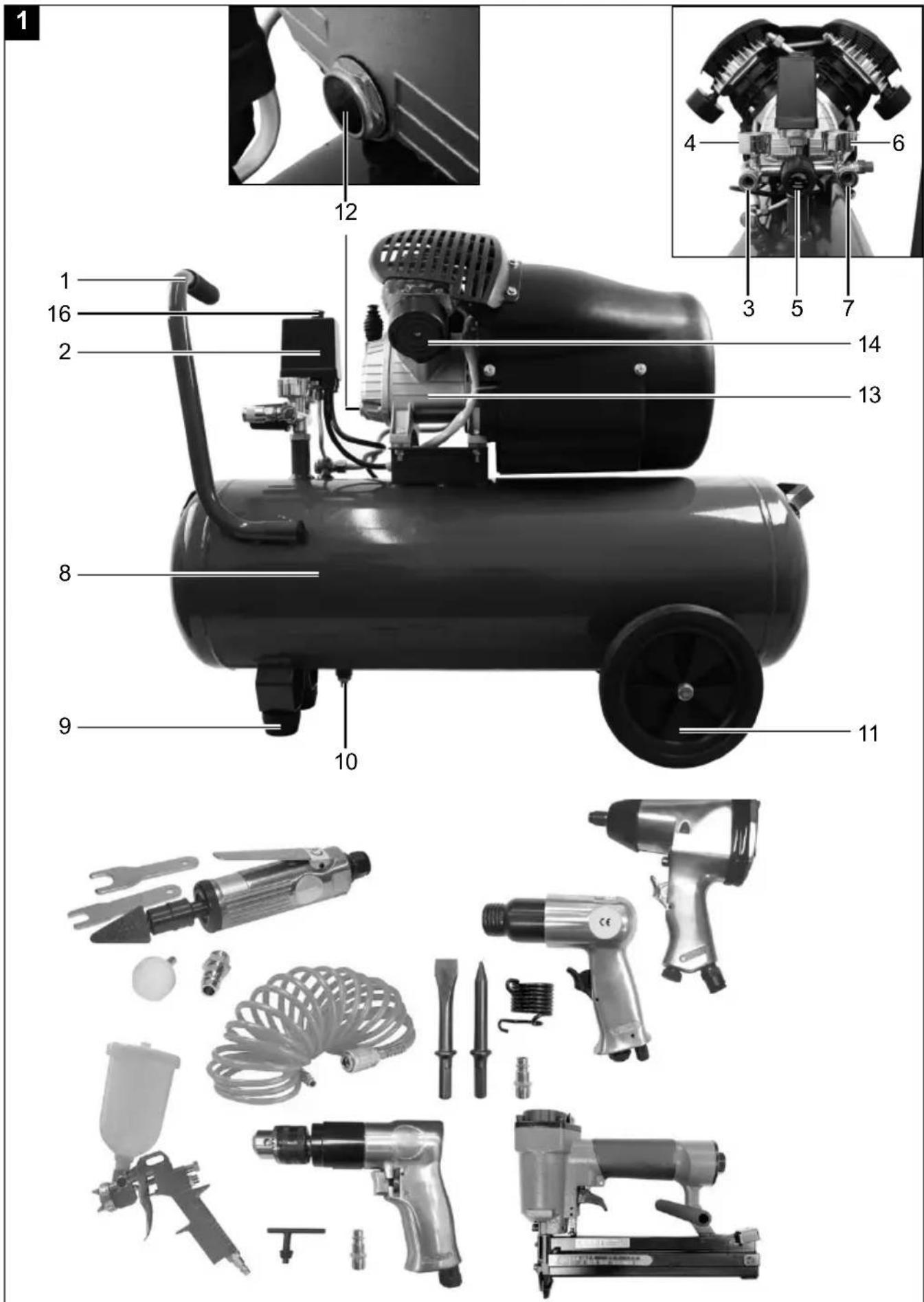
2. Device description (Fig. 1 - 14)
- Transport handle
- Pressure switch
- Quick coupling (regulated compressed air)
- Pressure gauge (set pressure can be read off)
- Pressure regulator
- Pressure gauge (vessel pressure can be read off)
- Quick coupling (unregulated compressed air)
- Pressure vessel
- Foot (2x)
- Drain screw for condensate
- Wheel (2x)
- Oil drain screw / Oil sight glass
- Compressor pump
- Air filter
- Oil plug
- ON/OFF switch
- Safety valve
- Oil filler hole
- Screw (wheel)
- Washer (wheel)
- Spring washer (wheel)
- Nut (wheel)
- Screw (foot)
- Washer (foot)
- Nut (foot)
3. Scope of delivery
- 2x air filters
- 2x feet
- 2x wheel
- 1x assembly material
- 1x oil plug
- 1x oil bottle
- 1x operating manual
• 5 m Spiral hose (7906100733) - Accessory set compressed air chisel hammer (7906102702)
• Air nail gun (7906102703)
• Compressed air impact wrench (7906102704)
• Air grinder (7906102705)
• Compressed air paint spray gun (7906102706)
• Compressed air drill driver (7906102701)
- Open the packaging and carefully remove the device.
- Remove the packaging material, as well as the packaging and transport safety devices (if present).
- Check whether the scope of delivery is complete.
- Check the device and accessory parts for transport damage.
- If possible, keep the packaging until the expiry of the warranty period.
ATTENTION!
The device and the packaging are not children's toys! Do not let children play with plastic bags, films or small parts! There is a danger of choking or suffocating!
4. Proper use
The compressor is used to generate compressed air for pneumatically powered tools that can be operated with an air rate of up to 272 l/min. (e.g. tyre inflaters, air blow guns, paint spray guns).
The compressor may only be operated in a dry and well ventilated indoor space.
The machine may only be used in the intended manner. Any use beyond this is improper. The user/operator, not the manufacturer, is responsible for damages or injuries of any type resulting from this.
Please observe that our equipment was not designed with the intention of use for commercial or industrial purposes. We assume no guarantee if the equipment is used in commercial or industrial applications, or for equivalent work.
5. Safety information
⚠ Attention! The following basic safety measures must be observed when using power tools for protection against electric shock, and the risk of injury and fire. Read all these notices before using the power tool and store the safety instructions well for later reference.
⚠ Attention! The following basic safety measures must be observed when using this compressor for protection against electric shock, and the risk of injury and fire. Read and observe these instructions before using the device
Safe work
- Keep the work area orderly
- Disorder in the work area can lead to accidents.
- Take environmental influences into account
- Do not expose power tools to rain.
- Do not use power tools in a damp or wet environment. There is a risk of electric shock!
- Make sure that the work area is well-illuminated.
-
Do not use power tools where there is a risk of fire or explosion.
-
Protect yourself from electric shock
-
Avoid physical contact with earthed parts (e.g. pipes, radiators, electric ranges, cooling units).
-
Keep away from children!
-
Do not allow other persons to touch the equipment or cable, keep them away from your work area.
-
Securely store unused electric tools
-
Unused power tools should be stored in a dry, elevated or closed location out of the reach of children.
-
Do not overload your power tool
-
They work better and more safely in the specified output range.
-
Dress properly
- Do not wear wide clothing or jewellery, which can become entangled in moving parts.
- Rubber gloves and anti-slip footwear are recommended when working outdoors.
-
Tie long hair back in a hair net.
-
Do not use the cable for purposes for which it is not intended
-
Do not use the cable to pull the plug out of the outlet. Protect the cable from heat, oil and sharp edges.
-
Take care of your tools
- Keep your compressor clean in order to work well and safely.
- Follow the maintenance instructions.
- Check the connection cable of the power tool regularly and have it replaced by a recognised specialist when damaged.
-
Check extension cables regularly and replace them when damaged.
-
Pull the connector out of the socket
- When the power tool is not in use or prior to maintenance and when replacing tools such as saw blades, bits, milling heads.
- Avoid inadvertent starting
-
Make sure that the switch is switched off when plugging the plug into an outlet.
-
Use extension cables for outdoors
- Only use approved and appropriately identified extension cables for use outdoors.
- Only use cable reels in the unrolled state.
- Always remain attentive
- Pay attention to what you are doing. Remain sensible when working. Do not use the power tool when you are distracted.
- Check the power tool for potential damage
- Protective devices or other parts with minor damage must be carefully inspected to ensure that they function correctly and as intended prior to continued use of the power tool.
- Check whether the moving parts function faultlessly and do not jam or whether parts are damaged. All parts must be correctly mounted and all conditions must be fulfilled to ensure fault-free operation of the power tool.
- Damaged protective devices and parts must be properly repaired or replaced by a recognised workshop, insofar as nothing different is specified in the operating manual.
- Damaged switches must be replaced at a customer service workshop.
- Do not use any faulty or damaged connection cables.
- Do not use any power tool on which the switch cannot be switched on and off.
- Have your power tool repaired by a qualified electrician
- This power tool conforms to the applicable safety regulations. Repairs may only be performed by an electrician using original spare parts. Otherwise accidents can occur.
- Attention!
- For your own safety, only use accessories and additional equipment that are indicated in the operating manual or have been recommended or indicated by the manufacturer. Use of other tools or accessories that those recommended in the operating manual or in the catalogue could represent a personal danger to you.
- Noise
- Wear hearing protection when using the compressor.
- Replacing the connection line
- If the connection line is damaged, it must be replaced by the manufacturer or an electrician to avoid danger. There is a risk of electric shock
- Inflating tyres
- Check the tyre pressure immediately after filling using a suitable pressure gauge, e.g. at a petrol station.
- Street-legal compressors in construction site operation
- Ensure that all hoses and fixtures are suitable for the maximum permissible working pressure of the compressor.
- Set-up location
- Only set up the compressor on a flat surface.
-
It is recommended to equip the feed hoses with a safety cable in case of pressure above 7 bar, e.g. using a wire cable.
-
Avoid over-stressing the piping system by using flexible hose connections to prevent kinking.
-
Use a residual current circuit breaker with a trigger current of 30 mA or less. Use of an RCD reduces the risk of electric shock.
⚠ WARNING! This power tool generates an electromagnetic field during operation. This field can impair active or passive medical implants under certain conditions. In order to prevent the risk of serious or deadly injuries, we recommend that persons with medical implants consult with their physician and the manufacturer of the medical implant prior to operating the power tool.
ADDITIONAL SAFETY INSTRUCTIONS
Observe the corresponding operating manuals of the respective compressed air tools / compressed air attachments! The following general instructions must also be observed:
Safety instructions for working with compressed air and blasting guns
- Ensure there is sufficient distance to the product, at least 2.50 m, and keep the compressed air tools / compressed air attachments away from the compressor during operation.
- The compressor pump and lines can become very hot during operation. Touching these parts will burn you.
- The air which is sucked in by the compressor must be kept free of impurities that could cause fires or explosions in the compressor pump.
- When releasing the hose coupling, hold the hose coupling piece with your hand.
- This way, you can protect yourself against injury from the rebounding hose.
- Wear safety goggles and a respirator when working with the compressed air pistol. Dusts are harmful to health! Foreign objects or blown off parts can easily cause injuries.
- Do not blow at people with the blow-out pistol and do not clean clothes while being worn. Risk of injury!
Safety instructions when using spraying attachments (e.g. paint sprayers):
- Keep the spray attachment away from the compressor when filling so that no liquid comes into contact with the compressor.
- Never spray in the direction of the compressor when using the spraying attachments (e.g. paint sprayers). Moisture can lead to electrical hazards!
- Do not process any paints or solvents with a flash point below 55°C. Risk of explosion!
- Do not heat up paints or solvents. Risk of explosion!
- If hazardous liquids are processed, wear protective filter units (face guards). Also, adhere to the safety information provided by the manufacturers of such liquids.
- The details and designations of the Ordinance on Hazardous Substances, which are displayed on the outer packaging of the processed material, must be observed. Additional protective measures are to be undertaken if necessary, particularly the wearing of suitable clothing and masks.
- Do not smoke during the spraying process and/or in the work area. Risk of explosion! Paint vapours are easily combustible.
- Never set up or operate the equipment in the vicinity of a fire place, open lights or sparking machines.
- Do not store or eat food and drink in the work area. Paint vapours are harmful to your health.
- The work area must exceed 30 m ^3 and sufficient ventilation must be ensured during spraying and drying.
- Do not spray against the wind. Always adhere to the regulations of the local police authority when spraying combustible or hazardous materials.
- Do not process media such as white spirit, butyl alcohol and methylene chloride with the PVC pressure hose. These media will destroy the pressure hose.
- The work area must be separated from the compressor so that it cannot come into direct contact with the working medium.
Operation of pressure vessels
- Anyone who operates a pressure vessel must keep this in good working order, operate and monitor it correctly, perform the necessary maintenance and servicing works immediately and implement safety measures as required according to the circumstances.
• The regulatory authority can instruct necessary monitoring measures in individual cases. - A pressure vessel must not be operated if it exhibits a defect that poses a danger to personnel or third parties.
- Check the pressure vessel for rust and damage each time before use. The compressor shall not be operated if the pressure vessel is damaged or rusty. If you discover damage, please contact the customer service workshop.
Keep these safety instructions in a safe place.
- Technical data
| Mains connection 230 V ~ 50 Hz | |
| Motor rating W 2200 | |
| Operating mode S1 | |
| Compressor speed 2850 min | -1 |
| Pressure vessel capacity (in liters) | 50 |
| Operating pressure approx. 10 bar | |
| Theoretical intake capacity (l/min) approx. 412 | |
| Effective delivery quantity at 7 bar | approx. 157 l/min |
| Effective delivery quantity at 4 bar | approx. 215 l/min |
| Effective delivery quantity at 1 bar | approx. 294 l/min |
| Protection type IPX2 | |
| Weight of the unit in kg approx. 41 | |
| Oil (15W 40) I approx. 0,25 | |
| Max. altitude (above mean sea level) | 1000 m |
Subject to technical modifications!
The noise emission values have been determined in accordance with EN ISO 3744.
Wear hearing protection.
Excessive noise can result in a loss of hearing.
⚠ Warning: Noise can have serious effects on your health. If the machine noise exceeds 85 dB, please wear suitable hearing protection.
| Sound power level L_WA | 93 dB |
| Sound pressure level L_pA | 71 dB |
| Uncertainty K_WA | 2.03 dB |
7. Before commissioning
- Before connecting the machine, make certain that the data on the type plate matches with the mains power data.
- Prior to initial commissioning, remove the transport plug (B) and fill the compressor pump housing with oil as described in item 8.4.
- Check the device for transport damage. Report any damage immediately to the transport company which was used to deliver the compressor.
• Install the compressor near the point of consumption. - Avoid long air lines and supply lines (extension cables).
• Make sure that the intake air is dry and free of dust. - Do not deploy the compressor in damp or wet areas.
- Operate the compressor only in suitable areas (well ventilated, ambient temperature +5°C to 40°C). There must be no dust, acids, vapours, explosive gases or inflammable gases in the room.
- The compressor is designed to be used in dry rooms. It is prohibited to use the compressor in areas where work is conducted with sprayed water.
- The oil level in the compressor pump must be checked before commissioning.
- The compressor may only be used outdoor briefly when the ambient conditions are dry.
- The compressor must always be kept dry and must not be left outdoors after work is complete.
8. Attachment and operation
Attention!
Always make sure the device is fully assembled before commissioning!
You require the following for assembly:
- 2 x open-ended spanner, 17 mm (not included in the scope of delivery)
- 2 x open-ended spanner 14 mm (not included in the scope of delivery)
8.1 Installing the wheels (Fig. 5)
• Fit the wheels (11) provided as shown.
8.2 Installing the foot (2x) (Fig. 6)
• Fit the feet (2x) provided as shown in.
8.3 Installing the air filter (2x) (Fig. 7, 8)
- Remove the transport plug (A) and screw the air filter (14) to the device.
8.4 Replacing the transport lid (B) (Fig. 9, 10)
- Remove the transport lid (A) of the oil filler hole (18).
- Fill the compressor oil supplied into the compressor pump housing and fit the enclosed oil plug (15) into the oil filler hole (18).
8.5 Mains power connection
- The compressor is equipped with a mains cable with protective contact plug. This can be connected to any mains socket 230 V\~ 50 Hz with an earth contact and that is protected at 16 A.
- Before commissioning, ensure that the mains voltage matches with the operating voltage and the machine's power rating on the type plate.
- Long supply cables, extensions, cable reels, etc. cause a drop in voltage and can impede motor start-up.
- In the case of temperatures below +5°C, motor starting can be endangered by sluggishness.
8.6 ON/OFF switch (Fig. 2)
- Pull the ON/OFF switch (16) upwards to switch on the compressor. Press the ON/OFF switch down to switch off.
8.7 Pressure adjustment: (Fig. 1, 3)
- The pressure at the manometer (4) is adjusted with the pressure regulator (5).
- The pressure set can be utilised by connecting to the quick-coupling (3).
• The boiler pressure is read off at the manometer (6). - The boiler pressure is taken at the quick-coupling (7).
8.8 Pressure switch setting (Fig. 1)
- The pressure switch (2) is set at the factory. Switch-on pressure ca. 6 bar Switch-off pressure ca. 8 bar
8.9 Thermal protection switch
The thermal protector is built into the device.
If the thermal protector has tripped, proceed as follows:
- Pull out the mains plug.
- Wait about two to three minutes.
- Plug the device in again.
- If the device does not start, repeat the process.
- If the device does not start again, switch the device off and on again at the on/off switch (16).
- If you have carried out all of the steps above and the device still does not work, contact our service team.
9. Electrical connection
The electrical motor installed is connected and ready for operation. The connection complies with the applicable VDE and DIN provisions. The customer's mains connection as well as the extension cable used must also comply with these regulations.
When working with spray attachments and during temporary use outdoors, the device must be connected to a residual current circuit breaker with a trigger current of 30 mA or less.
Important information
In the event of overloading, the motor will switch itself off. After a cool-down period (time varies) the motor can be switched back on again.
Damaged electrical connection cable.
The insulation on electrical connection cables is often damaged.
This may have the following causes:
- Pressure points, where connection cables are passed through windows or doors.
- Kinks where the connection cable has been improperly fastened or routed.
- Places where the connection cables have been cut due to being driven over.
- Insulation damage due to being ripped out of the wall outlet.
- Cracks due to the insulation ageing.
Such damaged electrical connection cables must not be used and are life-threatening due to the insulation damage.
Check the electrical connection cables for damage regularly. Ensure that the connection cables are disconnected from electrical power when checking for damage. Electrical connection cables must comply with the applicable VDE and DIN provisions. Only use connection cables with the designation "H05VV-F".
The printing of the type designation on the connection cable is mandatory.
AC motor:
- The mains voltage must be 230 V\~
- Extension cables up to 25 m long must have a cross-section of 1.5 square millimetres.
Connections and repair work on the electrical equipment may only be carried out by electricians.
Please provide the following information in the event of any enquiries:
• Type of current for the motor
• Data of machine type plate
• Data of motor type plate
10. Cleaning, maintenance and storage
⚠ Attention!
Pull out the mains plug before carrying out any cleaning and maintenance work! Risk of injury from electric shock!
⚠ Attention!
Wait until the equipment has cooled down completely! Danger of burning!
⚠ Attention!
Always depressurise the equipment before carrying out any cleaning and maintenance work! Risk of injury!
10.1 Cleaning
- Keep the device as free of dust and dirt as possible. Rub the device clean with a clean cloth or blow it off with compressed air at low pressure.
• We recommend that you clean the device directly after every use. - Clean the device at regular intervals using a damp cloth and a little soft soap. Do not use any cleaning products or solvents; they could attack the plastic parts of the device. Make sure that no water can penetrate the device interior.
- The hose and injection tools must be disconnected from the compressor before cleaning. The compressor must not be cleaned with water, solvents or similar.
10.2 Maintenance of the pressure vessel (Fig. 1) △ Attention!
To ensure a long service life for the pressure vessel (8), drain off the condensate after each use by opening the drain screw (10).
Release the boiler pressure beforehand (see 10.7.1). The drain screw is opened by turning it counterclockwise (when looking at the screw on the bottom of the compressor) so that the condensate can be completely drained out of the pressure vessel. Then close the drain screw again (turn clockwise). Check the pressure vessel for rust and damage each time before use.
The compressor shall not be operated if the pressure vessel is damaged or rusty. If you discover damage, please contact the customer service workshop.
Attention!
The condensate from the pressure vessel contains oil residue. Dispose of the condensate in an environmentally friendly manner at a suitable collection point.
10.3 Safety valve (Fig. 1, 3)
The safety valve (17) is set to the maximum permissible pressure of the pressure vessel. It is not permitted to adjust the safety valve or to remove the connection lock (17.2) between the drain nut (17.1) and its cap (17.3).
Actuate the safety valve every 30 operating hours but at least 3 times a year to ensure that it works when required. Turn the perforated drain nut (17.1) anti-clockwise to open it, then pull the valve stem outwards by hand via the perforated drain nut (17.1) to open the safety valve outlet. Now, the valve audibly releases air. Then turn the drain nut clockwise again to tighten.
10.4 Check the oil level at regular intervals (Fig. 11)
Place the compressor on a level and straight surface. The oil level must be positioned between the MAX and MIN of the oil sight glass (12).
Oil change: Recommended oil: SAE 5W 40 or equivalent.
The first oil filling must be changed after 10 operating hours; afterwards, perform an oil change every 50 operating hours.
10.5 Oil change (Fig. 1, 10, 11)
Switch the motor off and unplug the mains plug from the power outlet. Remove the oil plug (15). After releasing any air pressure, you can unscrew the oil drain screw (12) on the compressor pump (13).
To prevent the oil from running out in an uncontrolled manner, hold a small metal chute under the opening and collect the oil in a vessel. If the oil does not drain out completely, we recommend tilting the compressor slightly. Once the oil has fully drained out, replace the oil drain screw (12).
Dispose of the old oil at a drop-off point for old oil.
To fill in the correct quantity of oil, make sure that the compressor stands on an even surface. Fill the new oil into the oil filler hole (18) until the oil level reaches the maximum fill quantity. This is indicated by a red dot on the oil sight glass (12) (Fig. 11). Do not exceed the maximum filling quantity.
Overfilling the equipment may result in damage. Reinsert the oil plug (15) into the oil filler hole (18).
10.6 Cleaning the intake filter (Fig. 3, 12, 13)
The intake filter prevents dust and dirt being sucked in. It is necessary to clean this filter at least every 300 operating hours. A blocked intake filter significantly reduces the compressor power.
Remove the intake filter (2x) by opening the screw (E). Then pull off the filter cover (D). You can now remove the air filter (F).
Carefully knock out the air filter, filter cover and filter housing.
These components must then be blown out with compressed air (approx. 3 bar) and reassembled in reverse order.
10.7 Storage
⚠ Attention!
Pull out the mains plug and ventilate the equipment and all connected pneumatic tools. Store the compressor in such a way that it cannot be used by unauthorised persons.
Attention!
Store the compressor only in a dry location which is not accessible to unauthorised persons. Always store upright, never tilted! Oil may leak out!
10.7.1 Releasing overpressure
Release overpressure in the compressor by switching off the compressor and using up the compressed air still in the pressure vessel, e.g. with a compressed air tool running at idle or with an air blow gun.
10.8 Service information
With this product, it is necessary to note that the following parts are subject to natural or usage-related wear, or that the following parts are required as consumables.
Wearing parts*: Air filter
* may not be included in the scope of supply!
Spare parts and accessories can be obtained from our service centre. To do this, scan the QR code on the cover page.
11. Disposal and recycling
Notes for packaging


The packaging materials are recyclable. Please dispose of packaging in an environmentally friendly manner.
Notes on the electrical and electronic equipment act [ElektroG]
![SCHEPPACH GK520DCZ - Notes on the electrical and electronic equipment act [ElektroG] - 1](/content/2026/04/738712/images/8316dce22e8fa941ef867392be9f93e90647f6744aa6d0895bf8e104b00b6aba.jpg)
Waste electrical and electronic equipment does not belong in household waste, but must be collected and disposed of separately!
- Used batteries or rechargeable batteries that are not installed permanently in the old appliance must be removed non-destructively before disposal. Their disposal is regulated by the battery law.
- Owners or users of electrical and electronic devices are legally obliged to return them after use.
- The end user is responsible for deleting their personal data from the old device being disposed of!
- The symbol of the crossed-out dustbin means that waste electrical and electronic equipment must not be disposed of with household waste.
- Waste electrical and electronic equipment can be handed in free of charge at the following places:
-
Public disposal or collection points (e.g. municipal works yards)
-
Points of sale of electrical appliances (stationary and online), provided that dealers are obliged to take them back or offer to do so voluntarily.
- Up to three waste electrical devices per type of device, with an edge length of no more than 25 centimetres, can be returned free of charge to the manufacturer without prior purchase of a new device from the manufacturer or taken to another authorised collection point in your vicinity.
- Further supplementary take-back conditions of the manufacturers and distributors can be obtained from the respective customer service.
- If the manufacturer delivers a new electrical appliance to a private household, the manufacturer can arrange for the free collection of the old electrical appliance upon request from the end user. Please contact the manufacturer's customer service for this.
• These statements only apply to devices installed and sold in the countries of the European Union and which are subject to the European Directive 2012/19/EU. In countries outside the European Union, different regulations may apply to the disposal of waste electrical and electronic equipment.
12. Troubleshooting
| Fault Possible cause Remedy | ||
| The compressor does not start. | Mains voltage is not available. | Check the cable, mains plug, fuse and socket. |
| Mains voltage is too low. | Make sure that the extension cable is not too long. Use an extension cable with large enough wires. | |
| Outside temperature is too low. | Never operate with an outside temperature of below +5°C. | |
| Motor is overheated. | Allow the motor to cool down. If necessary, remedy the cause of the overheating. | |
| The compressor starts but there is no pressure. | Safety valve (17) leaking. Replace the safety valve (17). | |
| The seals are damaged. | Check the seals and have any damaged seals replaced by a service centre. | |
| Drain screw for condensate (10) leaking. | Tighten the screw by hand.Check the seal on the screw and replace if necessary. | |
| The compressor starts, pressure is shown on the pressure gauge, but the tools do not start. | The hose connections have a leak. | Check the compressed air hose and tools and replace if necessary. |
| A quick coupling has a leak. | Check quick coupling, replace if necessary. | |
| Insufficient pressure set on the pressure regulator (5). | Increase the set pressure with the pressure regulator. | |
Günzburger Straße 69
D-89335 Ichenhausen
Cher client,
text_image
Exploded view diagram of a mechanical device with numbered parts for identificationEC Declaration of Conformity
text_image
X 2000/14/EG_2005/88/EG Annex V Annex VI Noise: measured LWA = 91,2 dB; guaranteed LWA = 93 dB Notified Body: TÜV SÜD Industrie Service GmbH Westendstrasse 199 Notified Body No.: 0036 2016/1628/EU Emission. No: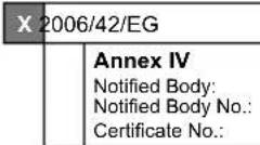
Standard references:
EN 1012-1:2010; EN 60204-1:2018; EN IEC 61000-6-3:2021; EN IEC 61000-6-1:2019
This declaration of conformity is issued under the sole responsibility of the manufacturer.
The object of the declaration described above fulfils the regulations of the directive 2011/65/EU of the European Parliament and Council from 8th June 2011, on the restriction of the use of certain hazardous substances in electrical and electronic equipment.
Subject to change without notice
Documents registrar: Ann-Katrin Bloching
Günzburger Str. 69, D-89335 Ichenhausen
Garantie DE
Apparent defects must be notified within 8 days from the receipt of the goods. Otherwise, the buyer's rights of claim due to such defects are invalidated. We guarantee for our machines in case of proper treatment for the time of the statutory warranty period from delivery in such a way that we replace any machine part free of charge which provably becomes unusable due to faulty material or defects of fabrication within such period of time. With respect to parts not manufactured by us we only warrant insofar as we are entitled to warranty claims against the upstream suppliers. The costs for the installation of the new parts shall be borne by the buyer. The cancellation of sale or the reduction of purchase price as well as any other claims for damages shall be excluded.