
DuraDry 70L - Air purifier Klarstein - Free user manual and instructions
Find the device manual for free DuraDry 70L Klarstein in PDF.

| Product Type | Dehumidifier |
| Dehumidification Capacity | 70 L/day (at 30 °C, 80 % RH) |
| Water Tank | 5.5 L |
| Rated Voltage | AC 220-240 V |
| Rated Frequency | 50 Hz |
| Max Rated Input Power | 860 W (30 °C, 80 % RH) |
| Max Rated Input Current | 3.9 A (30 °C, 80 % RH) |
| Sound Pressure Level | ≤ 52 dB(A) |
| Refrigerant | R290 (270 g) |
| Net Weight | 38 kg |
| Control Type | Electronic with LED display |
| Main Functions | Continuous mode, timer, humidity setting (5 % step), auto defrost, fault memory |
| Continuous Drainage | Yes (drain hose supplied) |
| Filter | Washable fabric filter |
| Safety | Overflow protection (FULL indicator), auto stop at 5 °C and 38 °C, 3-minute compressor self-protection |
| Maintenance | Regular filter cleaning, clean exterior with damp cloth |
| Storage | Dry before storage, store cord |
| Warranty | Consult manufacturer |
Frequently Asked Questions - DuraDry 70L Klarstein
User questions about DuraDry 70L Klarstein
0 question about this device. Answer the ones you know or ask your own.
Ask a new question about this device
Download the instructions for your Air purifier in PDF format for free! Find your manual DuraDry 70L - Klarstein and take your electronic device back in hand. On this page are published all the documents necessary for the use of your device. DuraDry 70L by Klarstein.
USER MANUAL DuraDry 70L Klarstein
bar
| Category | Value | |---|---| | Category 1 | 100 | | Category 2 | 100 | | Category 3 | 100 | | Category 4 | 100 | | Category 5 | 100 | | Category 6 | 100 | | Category 7 | 100 | | Category 8 | 100 | | Category 9 | 100 | | Category 10 | 100 | | Category 11 | 100 | | Category 12 | 100 | | Category 13 | 100 | | Category 14 | 100 | | Category 15 | 100 | | Category 16 | 100 | | Category 17 | 100 | | Category 18 | 100 | | Category 19 | 100 | | Category 20 | 100 | | Category 21 | 100 | | Category 22 | 100 | | Category 23 | 100 | | Category 24 | 100 | | Category 25 | 100 | | Category 26 | 100 | | Category 27 | 100 | | Category 28 | 100 | | Category 29 | 100 | | Category 30 | 100 | | Category 31 | 100 | | Category 32 | 100 | | Category 33 | 100 | | Category 34 | 100 | | Category 35 | 100 | | Category 36 | 100 | | Category 37 | 100 | | Category 38 | 100 | | Category 39 | 100 | | Category 40 | 100 | | Category 41 | 100 | | Category 42 | 100 | | Category 43 | 100 | | Category 44 | 100 | | Category 45 | 100 | | Category 46 | 100 | | Category 47 | 100 | | Category 48 | 100 | | Category 49 | 100 | | Category 50 | 100 | | Category 51 | 100 | | Category 52 | 100 | | Category 53 | 100 | | Category 54 | 100 | | Category 55 | 100 | | Category 56 | 100 | | Category 57 | 100 | | Category 58 | 100 | | Category 59 | 100 | | Category 60 | 100 | | Category 61 | 100 | | Category 62 | 100 | | Category 63 | 100 | | Category 64 | 100 | | Category 65 | 100 | | Category 66 | 100 | | Category 67 | 100 | | Category 68 | 100 | | Category 69 | 100 | | Category 70 | 100 | | Category 71 | 100 | | Category 72 | 100 | | Category 73 | 100 | | Category 74 | 100 | | Category 75 | 100 | | Category 76 | 100 | | Category 77 | 100 | | Category 78 | 100 | | Category 79 | 100 | | Category 80 | 100 | | Category 81 | 100 | | Category 82 | 100 | | Category 83 | 100 | | Category 84 | 100 | | Category 85 | 100 | | Category 86 | 100 | | Category 87 | 100 | | Category 88 | 100 | | Category 89 | 100 | | Category 90 | 100 | | Category 91 | 100 | | Category 92 | 100 | | Category 93 | 100 | | Category 94 | 100 | | Category 95 | 100 | | Category 96 | 100 | | Category 97 | 100 | | Category 98 | 100 | | Category 99 | 100 | | Total (Total) = [sum of bars] / [values] * (sum of bars + bars) * (sum of bars + bars) * (sum of bars + bars) * (sum of bars + bars) * (sum of bars + bars) * (sum of bars + bars) * (sum of bars + bars) * (sum of bars + bars) * (sum of bars + bars) * (sum of bars + bars) * (sum of bars + bars) * (sum of bars + bars) * (sum of bars + bars) * (sum in brackets) * (sum in brackets) * (sum in brackets) * (sum in brackets) * (sum in brackets) * (sum in brackets) * (sum in brackets) * (sum in brackets) * (sum in brackets) * (sum in brackets) * (sum in brackets) * (sum in brackets) * (sum in brackets) * (sum in brackets) * (sum in brackets) * (sum in brackets) * (sum in brackets) * (total).* (sum in brackets) * (sum in brackets) * (sum in brackets) * (sum in brackets) * (sum in brackets) * (sum in brackets) * (sum in brackets) * (sum in brackets) * (sum in brackets) * (sum in brackets) * (sum in brackets) * (sum in brackets) * (total).* (sum in brackets) * (sum in brackets) * (sum in brackets) * (sum in brackets)INHALT
natural_image
Line drawing of a portable industrial machine with a side-view inset showing its internal components (no text or symbols)natural_image
Line drawing of a portable industrial machine with a smaller box nearby, showing no text or symbols.
WARNUNG
natural_image
Symbol of a trash bin with crossed lines indicating no waste or discharge (no text or labels)Berlin Brands Group UK Limited
PO Box 42
272 Kensington High Street
London, W8 6ND
United Kingdom
Dear Customer,
Congratulations on purchasing this equipment. Please read this manual carefully and take care of the following hints to avoid damages. Any failure caused by ignoring the items and cautions mentioned in the instruction manual is not covered by our warranty and any liability. Scan the QR code to get access to the latest user manual and other information about the product.

CONTENT
Safety Instructions 22
Notes on Refrigerant R290 23
Service Precautions 25
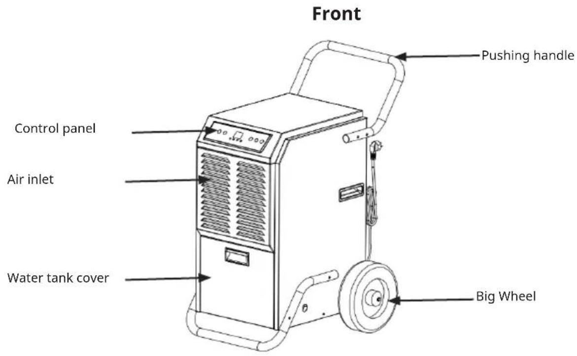
Product Description 28
Operation 32
Cleaning and Maintenance 34
Troubleshooting 34
Disposal Considerations 36
Manufacturer & Importer (UK) 36
TECHNICAL DATA
| Item number 10046368, 10 | 046371 10046369 | |
| Dehumidifying Capacity 51 | L/D(30 °C, RH 80%) 70L/D(30 °C, RH 80%) | |
| Rated Voltage AC 220-240 | V AC 220-240 V | |
| Rated Frequency 50 Hz 50 | Hz | |
| Max.Rated Input Power 65 | 0 W (30 °C,RH 80%) 860 W (30 °C, RH 80%) | |
| Max.Rated Input Current 3 | .1 A (30 °C, RH 80%) 3.9 A (30 °C,RH 80%) | |
| Water Tank Capacity 5.5 L | 5.5 L | |
| Sound Pressure Level | ≤52 dB (A) | ≤52 dB (A) |
| Refrigerant Charge | R290 230 g | R290 270g |
| Net Weight | 36 kg | 38 kg |
| Maximum Suction/exhaust side working pressure | 0.7 MPa/ 3.2 MPa | 0.7 MPa/ 3.2 MPa |
| Maximum permissible pressure on the high/low pressure side | 3.2 MPa | 3.2 MPa |
| Heat exchanger maximum allowable pressure | 3.2 MPa | 3.2 MPa |
SAFETY INSTRUCTIONS
- Please take the time to read this instruction manual before installing or using the appliance. This instruction booklet must be kept with the appliance for any future reference. If the appliance is sold or transferred to another person, ensure the booklet is passed on to the new user.
- This equipment is intended for use by skilled or trained operators in commercial, light industrial and agricultural settings, or for professional use by non-professionals.
- If the power cord is damaged, it must be replaced by the manufacturer, its service agent or similarly qualified persons to prevent hazards.
- The A-weighted sound pressure level is less than 45 dB.
- The unit must be disconnected from the mains during maintenance.
- Always operate the unit from a power source of the same voltage, frequency and amperage as indicated on the product label.
• Always use a grounded outlet. - Unplug the power cord when cleaning or when not in use.
- Do not operate with wet hands. Do not spill water on the unit.
- Do not immerse or expose the unit to rain, moisture or other liquids.
- Do not leave the machine running unattended. Do not tilt or overturn the unit.
- Do not unplug the power cord while the unit is in use.
- Do not unplug the unit by pulling on the power cord.
- Do not use an extension cord or adapter plug.
- Do not place anything on top of the unit.
- Do not climb on or sit on the unit.
- Do not put fingers or other objects into the air outlet.
- Do not touch the air inlet or the aluminium fins of the unit.
- Do not operate the unit if it has been dropped, damaged, or shows signs of product malfunction.
- Do not clean the unit with chemicals.
- Keep the unit away from fire, flammable or explosive objects.
• Install the unit in accordance with national wiring regulations. - Do not use any means to accelerate defrosting or cleaning other than those recommended by the manufacturer.
- The appliance must be stored in a room without continuous sources of heat (e.g. open flames, a gas appliance in operation or an electric heater in operation).
- Store the appliance in such a way as to avoid mechanical damage.
- Do not cut up or burn, even after use.
• Refrigerants must be odourless. - Pipework must be protected from physical damage and must not be installed in an unventilated room if the room is smaller than 12m^2 .
• National gas regulations must be observed. - Keep the required ventilation openings free of obstructions.
- The appliance must be stored in a well-ventilated area of the same size as the room in which it is to be operated.

WARNING
Any person involved in working on or entering a refrigerant circuit should hold a current, valid certificate from an industry-recognised assessment body attesting to their competence in the safe handling of refrigerants in accordance
with an industry-recognised assessment specification.

WARNING
Servicing must only be carried out as recommended by the equipment manufacturer. Maintenance and repairs requiring the assistance of other skilled personnel must be carried out under the supervision of a person competent in the use of
flammable refrigerants.
NOTES ON REFRIGERANT R290
Warnings
- The air conditioning system must be kept and transported upright. Otherwise, irreparable compressor damage may occur. Leave the unit for at least 24 hours before putting it into operation.
- Switch off the device and disconnect it from the power supply before cleaning.
- Make sure that the product creates a steady stream of air. Ensure the air inlets and outlets are not blocked.
- To prevent leaks, operate this unit on a horizontal surface.
- Any person performing work on a refrigerant circuit should have a current certificate from an industry-accredited assessment body. This ensures competence for the safe handling of refrigerants according to an industry-recognised assessment specification.
- If the device stops working, dispose of it properly.
- Store the device in a well-ventilated place when not in use.
- Store the device so that it is not damaged.
- Repairs may only be carried out by the manufacturer or an authorised specialist company.
- The cables connected to the device may contain potential ignition sources.
- Do not damage any components of the refrigerant circuit. Escaping refrigerant may not be noticed because it is odourless.
- Maintenance and repairs must be carried out under the supervision of specialists in the use of flammable refrigerants.
Information for rooms with refrigerant pipes
- Limit the piping to a minimum.
-
Be careful not to damage the piping.
-
Appliances with flammable refrigerants may only be installed in a well-ventilated room.
- Comply with national gas regulations.
- All mechanical connections must be freely accessible for maintenance purposes.
CAUTION
Risk of fire! This device contains the flammable refrigerant R290. If the refrigerant escapes and is exposed to an external ignition source, there is a risk of fire.
SERVICE PRECAUTIONS
When servicing a dehumidifier with R290, please observe the following warnings.
Area checks
Before starting work on systems containing flammable refrigerants, safety checks must be carried out to ensure that the risk of ignition is minimised. If the refrigeration system is to be repaired, the following precautions must be taken before any work is carried out on the system.
Procedure
Work must be carried out using a controlled procedure to minimise the risk of flammable gas or vapour being present during the work.
General work area
All maintenance personnel and others working in the local area shall be instructed as to the nature of the work to be carried out. Avoid working in confined spaces. The area around the work area should be cordoned off. Ensure that conditions within the area have been made safe by controlling flammable materials.
Check for presence of refrigerant
Check the area with an appropriate refrigerant detector before and during the work to ensure that the technician is aware of any potentially flammable atmosphere. Ensure that the leak detection equipment used is suitable for use with flammable refrigerants, i.e. non-sparking, adequately sealed or intrinsically safe.
Presence of fire extinguishers
If hot work is to be carried out on the refrigeration unit or any associated parts, suitable fire extinguishing equipment must be available. A dry powder or CO2 fire extinguisher should be kept close to the loading area.
No ignition sources
No person carrying out work on a refrigeration system which involves the exposure of pipework containing or having contained flammable refrigerant shall use any source of ignition in such a way as to create a risk of fire or explosion. All possible ignition sources, including cigarette smoking, shall be kept sufficiently distant from the site of installation, repair, removal and disposal where flammable refrigerant may be released into the surrounding atmosphere. Before starting work, the area around the equipment must be inspected to ensure that there are no flammable or ignition hazards. „No smoking“ signs should be posted.
Ventilated area
Ensure that the area is outdoors or adequately ventilated before entering the system or carrying out hot work. Some ventilation must be maintained while the work is being carried out. The ventilation should safely disperse any released refrigerant, preferably to the outside atmosphere.
Checks on the refrigeration system
When electrical components are changed, they must be fit for purpose and to the correct specification. The manufacturer's maintenance and service instructions must always be followed. If in doubt, the manufacturer's technical department should be consulted.
The following checks must be carried out for systems using flammable refrigerants:
- The size of the charge is appropriate to the size of the room in which the refrigerant-containing parts are installed;
- that the fans and vents are working properly and are not obstructed;
- If an indirect circuit is used, the secondary circuit is checked for the presence of refrigerant;
- Markings on the equipment are still visible and legible. Illegible markings and signs shall be corrected;
- Refrigerant lines or components are installed in a position where they are unlikely to be exposed to substances that could corrode refrigerant-containing components, unless the components are constructed of materials that are inherently resistant to corrosion or are adequately protected against such corrosion.
Inspection of electrical equipment
Repair and maintenance of electrical components shall include initial safety checks and component inspection procedures. If there is a fault which could compromise safety, no electrical supply shall be connected to the circuit until it has been satisfactorily rectified. If the fault cannot be rectified immediately but it is necessary to continue operation, an appropriate temporary solution shall be used. This must be reported to the owner of the equipment so that all parties are advised.
Initial safety checks should include
- that the capacitors are discharged: this must be done in a safe manner to avoid the possibility of sparking;
- that no live electrical components or wiring are exposed during charging, recovery or purging of the system;
- that there is continuity of earth connection.
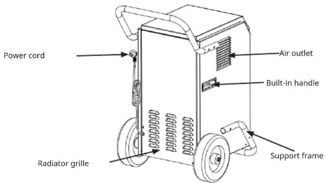
PRODUCT DESCRIPTION
Back
Handle and Support Frame Installation
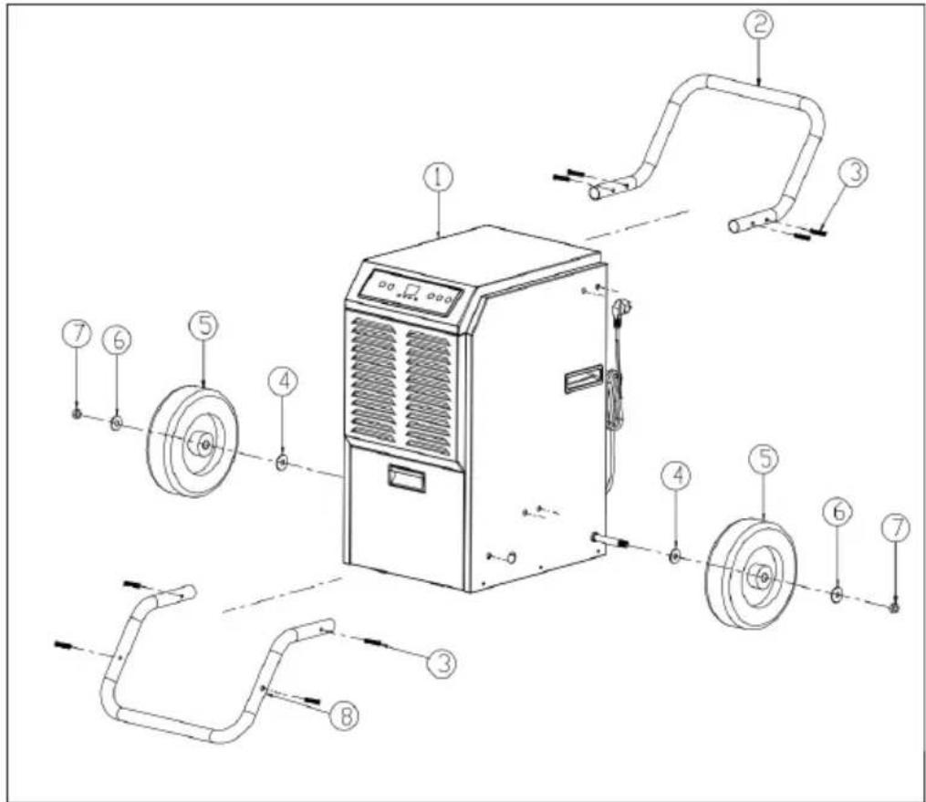
| 1 Main body 2 Handle | |
| 3 Stainless Steel Bolt | 4 Spacer |
| 5 Wheel 6 Spacer | |
| 7 Nut | 8 Support Frame |
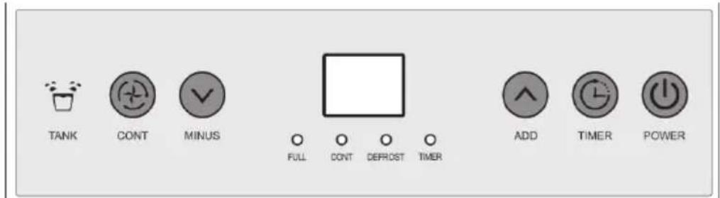
Control Panel
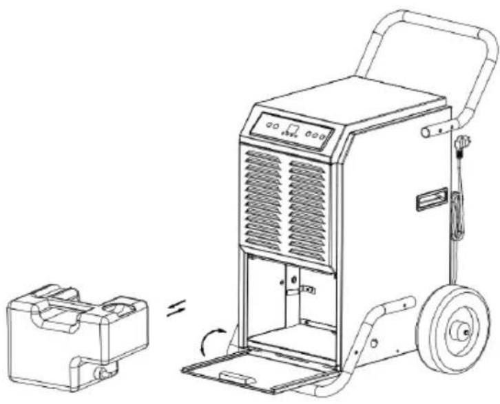
Drainage Installation
- When the tank is full, the "FULL" light comes on.
- The machine will also make a buzzing sound. To stop this, press the power button to switch off the machine.
- To empty the water tank, open the front panel to access the water tank.
- Grasp the handle of the water tank and pull it out horizontally.
- When the water has been disposed of, replace the tank and close the front panel.
natural_image
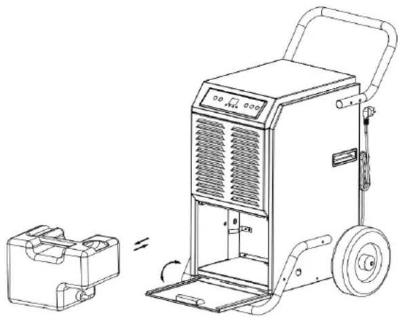
Line drawing of a portable electric heater with a side-view inset showing its internal components (no text or symbols)Continuous drainage
In extremely wet conditions the hopper may need to be emptied frequently. It can be set up for continuous emptying by doing the following:
- Open the front cover, remove the hopper and drain the water from the hopper.
- Remove the plug and fit the drain pipe supplied to the connector, directing the pipe to the required area before operating the machine. See the pictures below.
- Ensure that the water tank and drain pipe are not blocked, close the front panel.
- If you do not use continuous drainage and want to use the water tank again, simply use the plug to stop the water from flowing out of the connector.
natural_image
Line drawing of a portable air purifier with a side-view inset showing internal components (no text or symbols)
WARNING
Do not block the drain hose. The end of the drain pipe should not be higher than the drain hole. If the end of the drain pipe is higher than the outlet hole, water will not drain properly and may damage parts of the appliance.
OPERATION
Button functions
POWER button
Press this button while the appliance is on, the display lights up, the appliance automatically enters the continuous mode, the display shows the ambient humidity, the compressor starts after the fan runs for 3 seconds; press this button again, the compressor stops, the display shows "- -", the appliance enters the standby mode, the fan runs for another minute and then stops.
TIMER button
Press this key while the machine is on, until the key light comes on, press "MINUS" and "ADD" to set the time to start the machine, when the countdown is over, the fan and compressor start working.
Press this key while the machine is running, until the key light comes on, press "MINUS" and "ADD" to set the time to stop the machine, when the countdown is over, the fan and compressor stop working.
Pressing this key for 3 seconds shows the current temperature, after 10 seconds it returns to the current humidity. Press and hold this button to display the temperature.
ADD button
Increase the humidity by pressing this button in normal mode, humidity increase 5%RH with each press, buzzer rings each time with each press, press this button for 1 second can increase the humidity continuously; press this button to set the time after pressing "TIMER".
MINUS button
Decrease the humidity by pressing this button in normal mode, humidity decrease 5%RH with each press, buzzer rang each time with the press, pressing the button for 1 second can decrease the humidity continuously; press this button to set the time after pressing "TIMER".
Note:
The default humidity is 50 % RH, which can be increased or decreased as follows 20%-25%--30%-35%-40%45%-50%-55%-60%-65%-70%-75%-80%-85%-90%
The ambient humidity and the humidity set on the machine determine the status of the compressor and fan as follows:
- Ambient humidity≥machine set humidity+3%, compressor and fan start running.
- Ambient humidity < machine set humidity+3%, compressor and fan stop running.
- Press Continue key in continuous mode, switch to normal dehumidification mode, set humidity manually.
CONT button
Continuous mode---(display screen shows current humidity) machine keeps running, continuous mode light on, humidity set is invalid, time set is available. Press continuous mode to switch to normal mode, continuous mode light off, humidity set is operational.
Functions
1 5 seconds after the water tank is full, the alarm sounds, the water tank light turns red, the buzzer sounds 15 times, the compressor and fan stop, after the water tank is empty, the machine automatically returns to the previous mode, the compressor starts after 3 minutes of self-protection. Alarm stops in 3 seconds after water tank is emptied and replaced, fan starts, compressor starts in 3 minutes.
2 Compressor does not need 3 minutes for self-protection if it was the first time to start the machine, press "POWER" and power off; power on, press "POWER", compressor starts immediately.
3 The system has an automatic memory. When all the mode settings have been completed, if there is a sudden power cut during operation or the power plug is removed, the system can store the current status before the power cut and automatically enter the operating mode before the power cut after the power is restored.
Defrost function
1) Ambient temperature < 5 °C or ambient temperature >38 °C, compressor and fan stop.
2) Defrost demand: Compressor runs for 30 minutes, temperature sensor sense the temperature ≤-1 °C, (last for 10 seconds), compressor stops, defrost starts, fan continues, defrost light on, when pipe temperature goes to 5 °C or defrost last for 15 minutes, defrost stops.
Note: During defrosting, the light won't be off until the defrost process is over.
CLEANING AND MAINTENANCE
Cleaning
-
Clean the machine with a soft damp cloth.
-
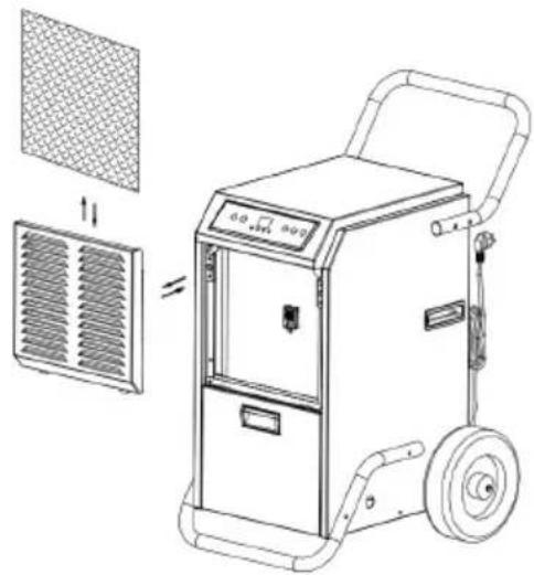
Pull out the louver on the front panel to gain access to the filter.
natural_image
Technical line drawing of a portable air conditioner unit with mesh panel and side-mounted fan (no text or symbols)-
Remove the filter mesh from the unit.
-
Use a clean cloth to absorb the surface dust on the filter mesh. If the filter is extremely dirty, use tap water to rinse the filter. Allow the filter to dry completely before replacing it in the air inlet grille. A clean filter will increase the capacity of the machine.
Storage
- If you don't use the machine for a long time, please store it according to the following steps:
- Clean the filter cloth.
- ATTENTION: The evaporator inside the machine must be dried before packing the unit to avoid damage to components and mould.
- Unplug the unit and leave it in a dry, open area for several days to dry out. Another way to dry the unit is to set the humidity point more than 2% higher than the ambient humidity to force the fan to dry the evaporator for a few hours.
- Collect the power cord, bunch it and hang it in the power cord bag on the back of the unit.
- Store in a clean and dry environment.
TROUBLESHOOTING
| Problem Possible Cause Solution | ||
| Machine does not work Unit | it is not plugged in Plug in the unit | |
| Room temperature under 5 degrees or above 35 degrees | To protect the machine, use it only when ambient temperature is between 5 and 35 degrees. | |
| Machine runs but does not dehumidify | When the humidity set point is 2% higher than ambient humidity. | Reset the humidity to a lower set point, or power off the machine if the humidity has satisfied you. |
| Reduced dehumidifier capacity | Filter mesh jammed Clean | the filter mesh according to manual |
| No air inlet Air-in and/or air-out louvers jammed | Remove the blockage from the air intake and/or exhaust louvers. | |
| Clean the filter according to the instructions or remove the blockage from the louvre. | ||
| Loud Operation Machine placed on a sloping or inclined surface | Move to level ground | |
| Filter screen is blocked Clean filter mesh according to instructions | ||
DISPOSAL CONSIDERATIONS
natural_image
Symbol of a trash bin crossed with a diagonal line, no text or numbers presentIf there is a legal regulation for the disposal of electrical and electronic devices in your country, this symbol on the product or on the packaging indicates that this product must not be disposed of with household waste. Instead, it must be taken to a collection point for the recycling of electrical and electronic equipment. By disposing of it in accordance with the rules, you are protecting the environment and the health of your fellow human beings from negative consequences. For information about the recycling and disposal of this product, please contact your local authority or your household waste disposal service.
MANUFACTURER & IMPORTER (UK)
Manufacturer:
Chal-Tec GmbH, Wallstrasse 16, 10179 Berlin, Germany.
Importer for Great Britain:
Berlin Brands Group UK Limited
PO Box 42
272 Kensington High Street
London, W8 6ND
United Kingdom
Estimado cliente:
ÍNDICE
natural_image
Line drawing of a portable industrial machine with a smaller box nearby, showing no text or symbols.Drenaje continuo
natural_image
Line drawing of a portable air purifier with a side-view inset showing internal components (no text or symbols)
ADVERTENCIA
natural_image
Technical line drawing of a portable air conditioner unit with mesh panel and side-mounted fan (no text or symbols)natural_image
Symbol of a trash bin with crossed lines indicating no waste or discharge (no text or labels)Berlin Brands Group UK Limited
PO Box 42
272 Kensington High Street
London, W8 6ND
United Kingdom
Chère cliente, cher client,
SOMMAIRE
natural_image
Line drawing of a portable industrial machine with a side-view inset showing its internal components (no text or symbols)Drainage continu
natural_image
Line drawing of a portable industrial machine with a smaller box and wheels, showing no text or symbols.
MISE EN GARDE
20% -25% --30% -35% -40% -45% -50% -55% -60% -65% -70% -75% -80% -85% -90%
natural_image
Technical line drawing of a portable air conditioner unit with mesh panel and side-mounted fan (no text or symbols)natural_image
Symbol of a trash bin with crossed lines indicating no waste or discharge, and a solid black rectangle below (no text or labels)Berlin Brands Group UK Limited
PO Box 42
272 Kensington High Street
London, W8 6ND
United Kingdom
Gentile cliente,
INDICE
natural_image
Line drawing of a portable industrial machine with a smaller box nearby, showing no text or symbols.Scarico continuo
natural_image
Line drawing of a portable industrial machine with a smaller box nearby, showing no text or symbols.
AVVERTENZA
natural_image
Technical line drawing of a portable air conditioner unit with mesh panel and side-mounted fan (no text or symbols)natural_image
Symbol of a trash bin with crossed lines indicating no waste or discharge, and a solid black rectangle below (no text or labels)Berlin Brands Group UK Limited
PO Box 42
272 Kensington High Street
London, W8 6ND
United Kingdom

KLARSTEIN


- INHALT
- WARNUNG
- Dear Customer,
- CONTENT
- SAFETY INSTRUCTIONS
- WARNING
- NOTES ON REFRIGERANT R290
- Warnings
- Information for rooms with refrigerant pipes
- CAUTION
- SERVICE PRECAUTIONS
- Area checks
- Procedure
- General work area
- Check for presence of refrigerant
- Presence of fire extinguishers
- No ignition sources
- Ventilated area
- Checks on the refrigeration system
- The following checks must be carried out for systems using flammable refrigerants:
- Inspection of electrical equipment
- Initial safety checks should include
- PRODUCT DESCRIPTION
- Drainage Installation
- Continuous drainage
- OPERATION
- Button functions
- POWER button
- TIMER button
- ADD button
- MINUS button
- Note:
- CONT button
- Functions
- Defrost function
- CLEANING AND MAINTENANCE
- Cleaning
- Storage
- TROUBLESHOOTING
- DISPOSAL CONSIDERATIONS
- MANUFACTURER & IMPORTER (UK)
- Manufacturer:
- Importer for Great Britain:
- Estimado cliente:
- ÍNDICE
- Drenaje continuo
- ADVERTENCIA
- SOMMAIRE
- Drainage continu
- MISE EN GARDE
- Gentile cliente,
- INDICE
- Scarico continuo
- AVVERTENZA
- KLARSTEIN
Brand : Klarstein
Model : DuraDry 70L
Category : Air purifier