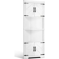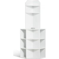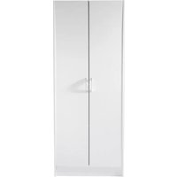
A02D.2056 - Wardrobe Vevor - Free user manual and instructions
Find the device manual for free A02D.2056 Vevor in PDF.


User questions about A02D.2056 Vevor
0 question about this device. Answer the ones you know or ask your own.
Ask a new question about this device
Download the instructions for your Wardrobe in PDF format for free! Find your manual A02D.2056 - Vevor and take your electronic device back in hand. On this page are published all the documents necessary for the use of your device. A02D.2056 by Vevor.
USER MANUAL A02D.2056 Vevor
Technical support and E-warranty certif cate Www. vevor. com/support
SIDEBOARD
MODEL: A02D. 2056
we continue to be committed to provide y u tools with competitive price. "save Half", "Half price" or any other similar expressions used by us only represents an estimate of savings y u might benefit from buying certain tools with us compared to the ma top brands and does not necessarily mean to cover all categories of tools offered by us. You are kindly reminded to verify carefully When y u are Placing an order with use if y actua ly saving half in comparison with the top net brands.
MODEL: A02D.2056
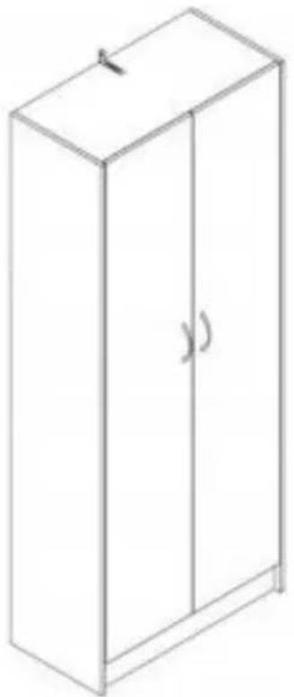
natural_image
Line drawing of a two-decker cabinet with a handle and door (no text or symbols)NEED HELP? CONTACT US!
Have product questions? Need technical support? Please feel free to contact us:
Technical Support and E-Warranty Certificate www.vevor.com/support
This is the original instruction, please read all manual instructions carefully before perating. VEVOR reserves a clear interpretation of user manual. The appearance of the product shall be subject to the product you received. Please forgive us that we won't inform you there are any technology or software updates on our product.
| warning-To reduce the risk of injury, user must read instructions manual carefully. | |
 | wear eye protection.wear protective gloves |
SAFETY WARNINGS AND PRECAUTIONS
Thank you for using this product. In order to make sure that you can operate machine correctly, read this instruction carefully before peration and keep it properly for future reference. please be sure to read the precautions and safety rules in this page to ensure your safe use. This manual will outline safety warning and precautions, operating, maintenance and cleaning. The warnings and instructions reviewed in this manual cannot cover all possible conditions and situations that may occur. Caution and common sense are not built into this product, since we believe that the uses will comply with these codes. Please read ALL the instruction on our home in negy
-
Assemble needs to follow these instructions. Incorrect assembly can be a hazard.
-
wear safety g ggles and heavy-duty work gloves during assembly.
-
Do not assemble when tired or when under the inf of alcohol, drugs or medication.
4 .weight and other product properties are only applicable to correct y and completely assembled products.
-
keep the assembly area clean and well-lit.
-
keep bystanders out of the area during assembly.
-
This product is not a toy. Do not allow children and pet to play with or a this item
-
use as intended only. Do not sit or stand on the product.
-
Inspect before every use. Do not use it if parts are loose or damaged.
-
For indoor use only.
1 1 . Do not exceed the listed weight capacity. Tighten all knobs securely before applying load . Be aware of dynamic loading! The sudden load movement may briefly create an excess s load , causing product failure .
12. Do not apply this unit to any other purp ses than the indicated usage.
13. Do not use it outdoors or for commercialoesp. INDOOR USE ONLY
14. DO NOT CLEAN IT WITH ANY ABRASIVE MATERIAL
15. Never leave it unattended while in use.
17. pay attention to hand injuries caused by drawer pinching!
18. Do not place the product on or near hot air, electric burners, or heaters
19. Do not place in a damp environment.
20. The product should be placed on at surface.
△WARNING: To PREVENT SERIOUS INJURY AND DEATH FROM TIPPING:
-
Attention: An anti tipping device must be installed to securely secure the product to the wall (Ensure the reliability of the wall itself).
-
This appliance is not intended for use by young r infirm persons unless supervised by a responsible person to ensure that they can use the appliance safely. young children should be supervised to ensure that they do not play with the product. children and pets should stay away from the product.
PRODUCT PARAMETERS
| MODEL | Loading capacity |
| A02D. 2056 | Max50kg (About 110LBS) |
CAUTION:
-
Do not Place all the weights on the same layer!
-
place the weight evenly on each layer Plate to achieve the maximum bearir capacity!
ASSEMB Y STEPS
- please dispose of all Plastic bags carefully and keep them away from children and pet.
2 . check all components provided according to the list in this manual . Make ;you have all of the parts listed . - whilst every care is taken in the manufacture of this product, care must be during assembly in case sharp edges are present.
- wear eye protection, protective gloves, during assembly and using.
- The product should be placed on datf surface.
- The product requires two people to assemble.
- The product requires the use of a rubber hammer and a phillips screwdriver (Rubber hammer and cross screwdriver need to be purchased by oneself).
- If uneven product gaps are found, they can be disassembled and adjusted.
Attention: An anti tipping device must be installed to securely secure the product to the wall (Ensure the reliability of the wall itself).
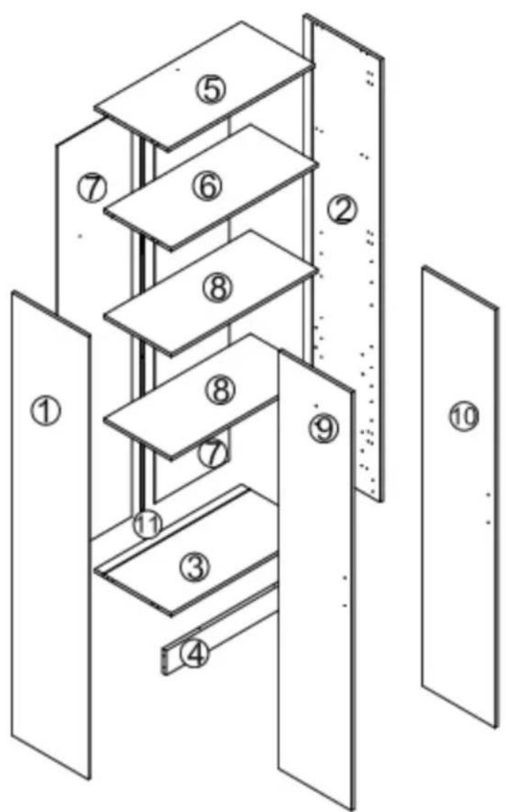
text_image
Technical diagram of a multi-level building structure with numbered components, likely for architectural or engineering purposes.
text_image
A x18 B x18 C x12 D x36 E x8 F x8 G x8 H x2 I x4 J x6 K x1 L x1 M x1 N x1 O x4 4x30mm 4x14mm 3x16mm 4x20mmNote: the quantity of parts shown in the manual is the actual usage and the unused parts are spare parts.
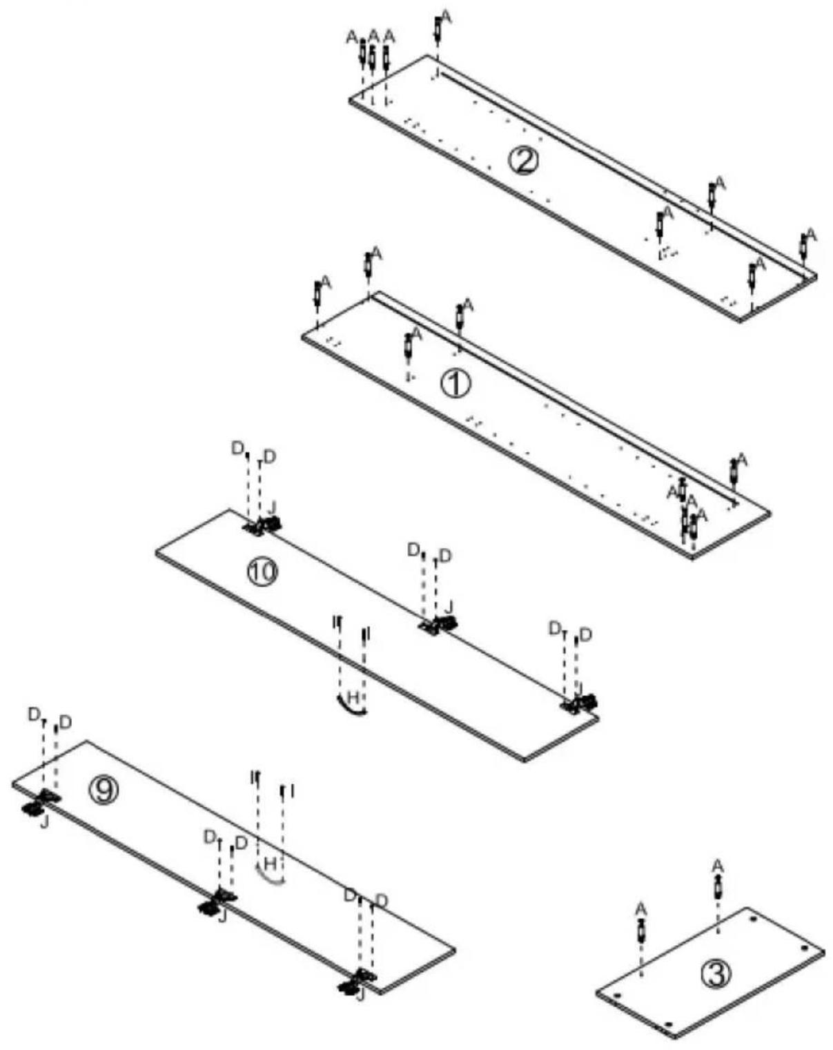
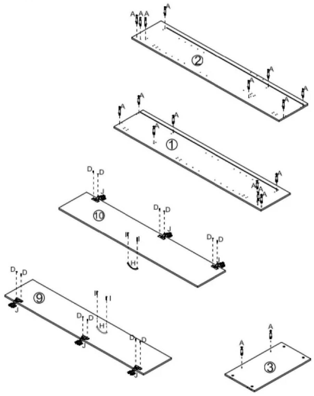
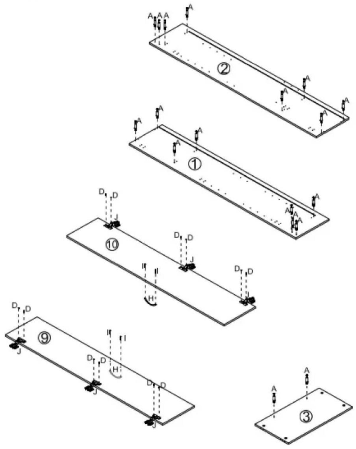
Step 1
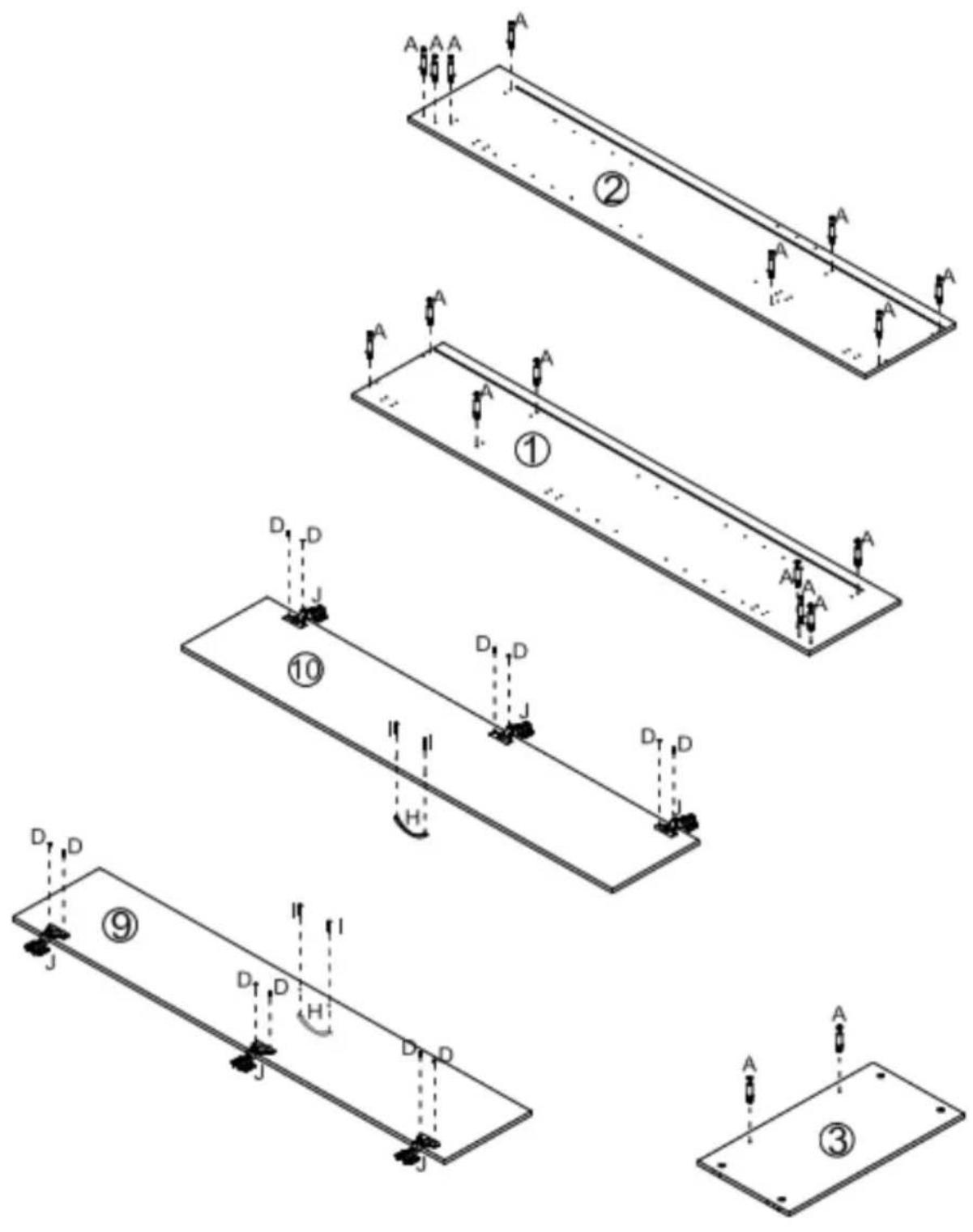
text_image
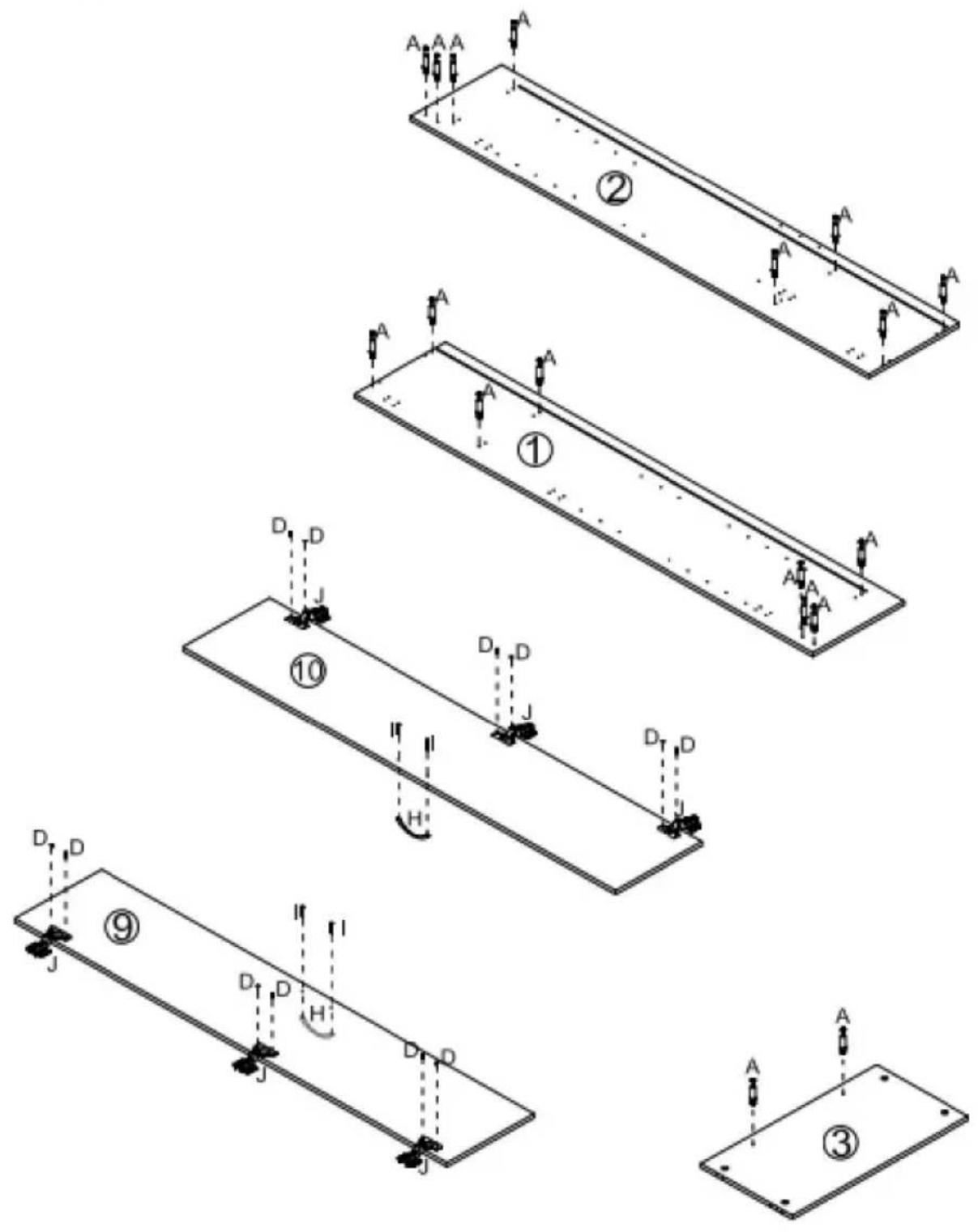
Technical diagram showing nine sequential steps of a mechanical or structural assembly with labeled components (A, D, J) and directional arrows indicating motion.
text_image
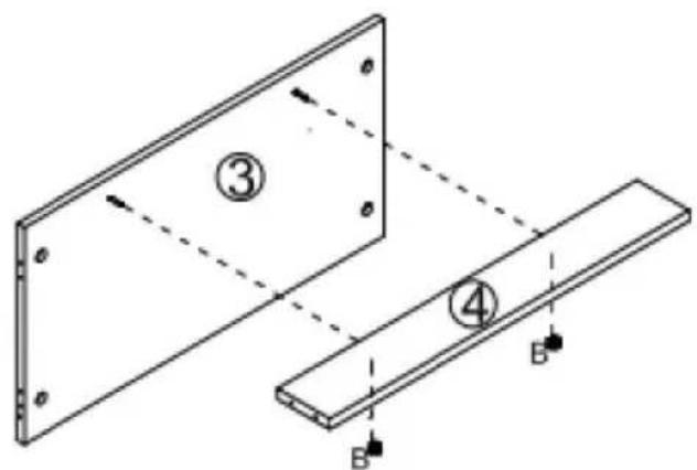
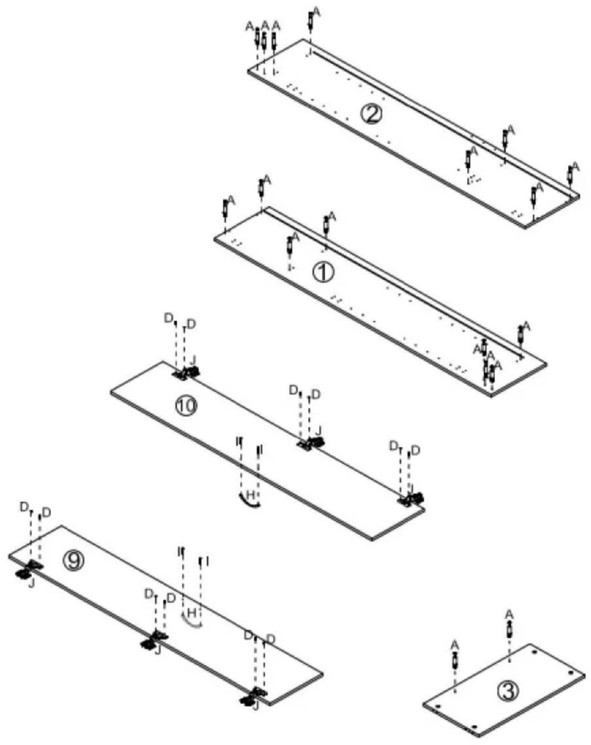
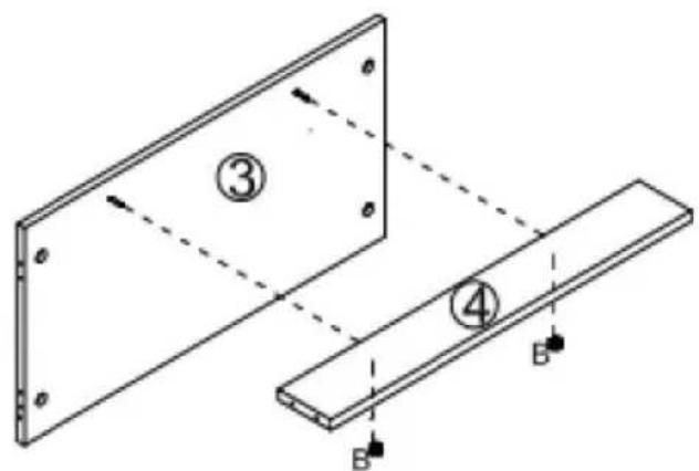
A x18 J x6 D x12 H x2 I x4Step 2
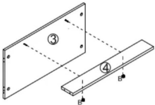
text_image
Technical diagram showing two structural components with labeled parts and alignment indicators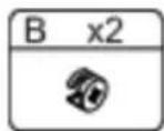
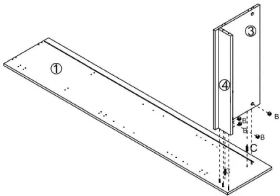
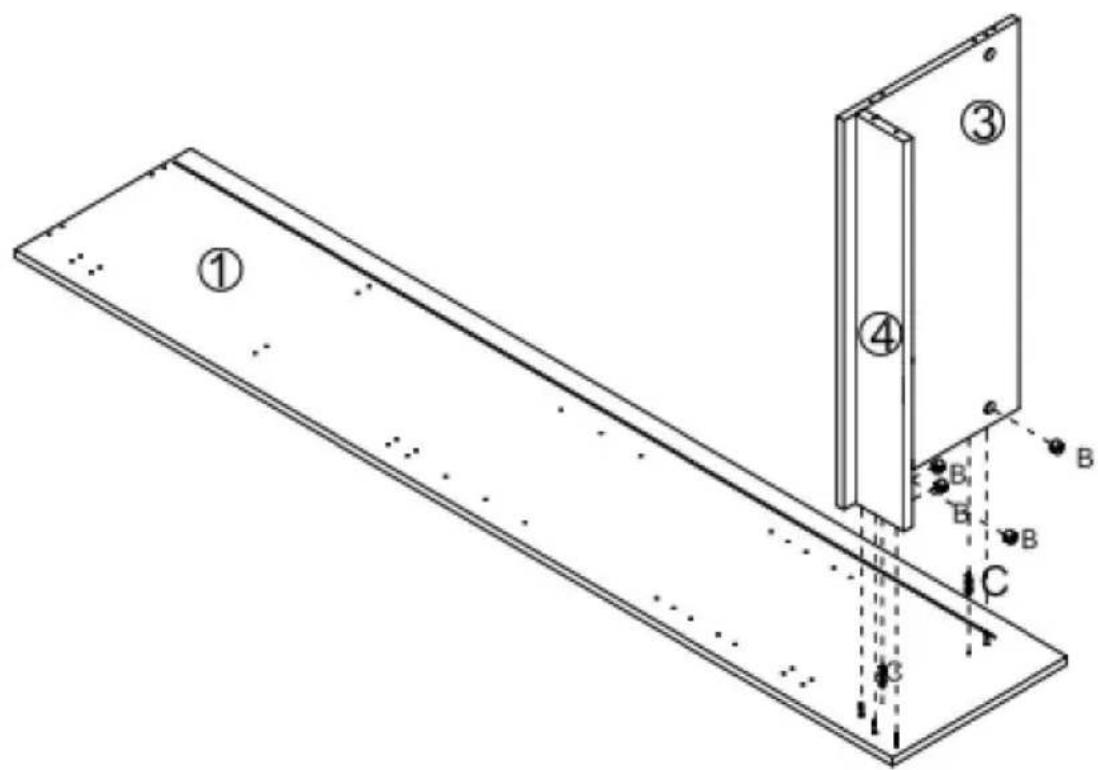
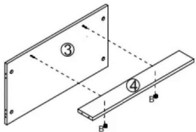
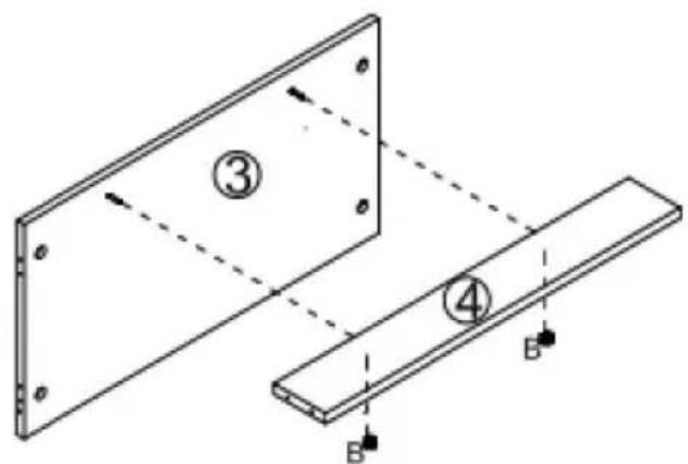
Step 3
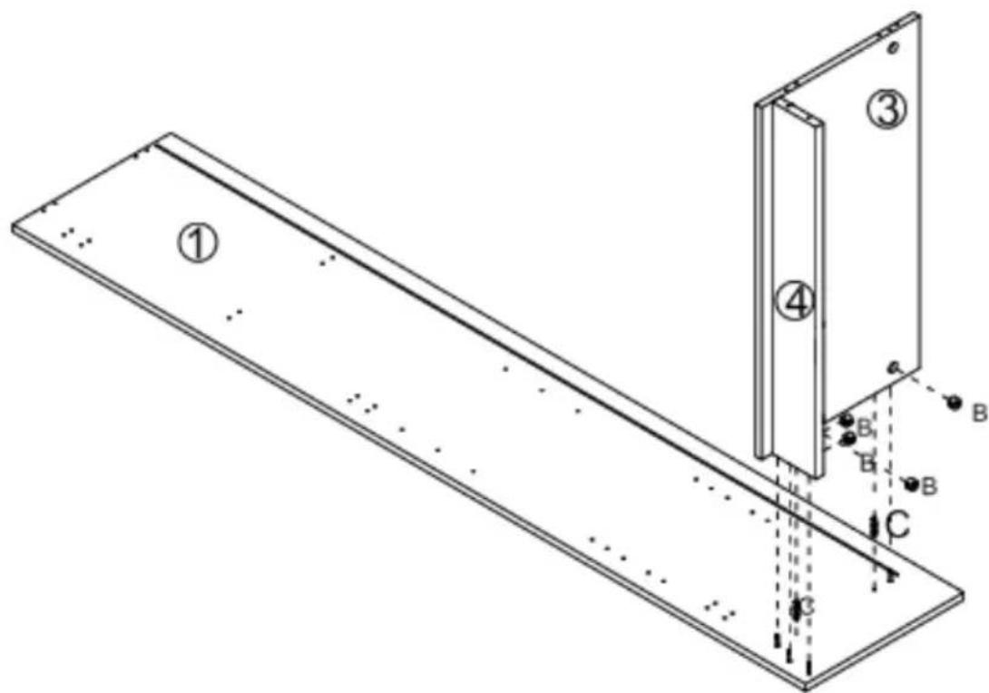
text_image
Technical diagram showing a 3D mechanical assembly with labeled components and directional arrows indicating motion or force.| B x4 | C x2 |
 |
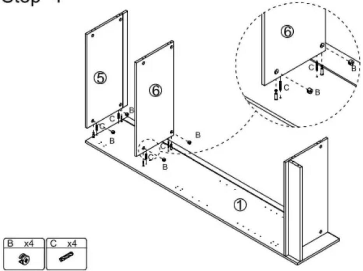
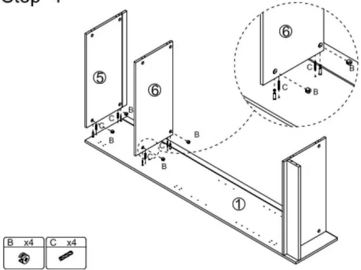
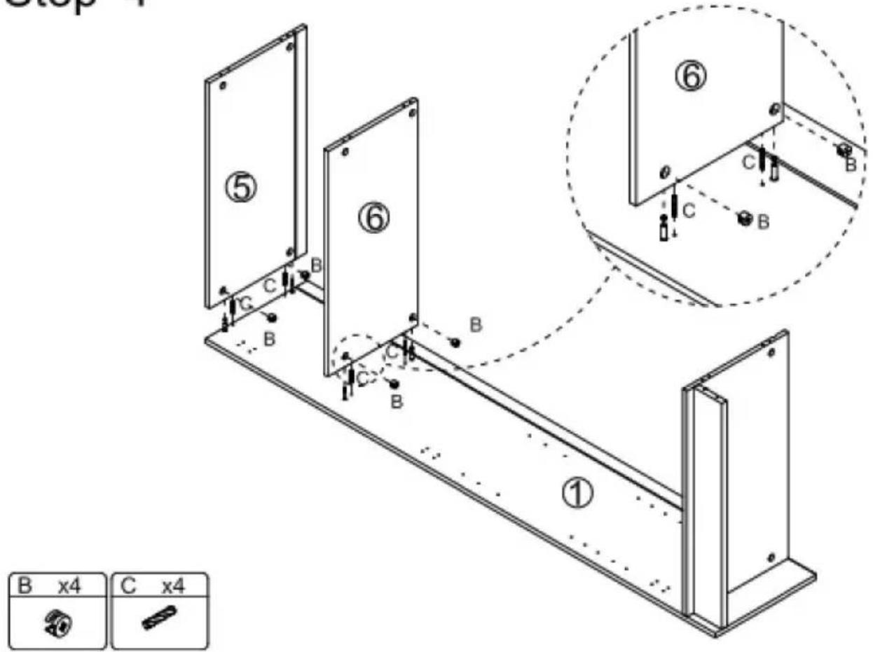
Step 4
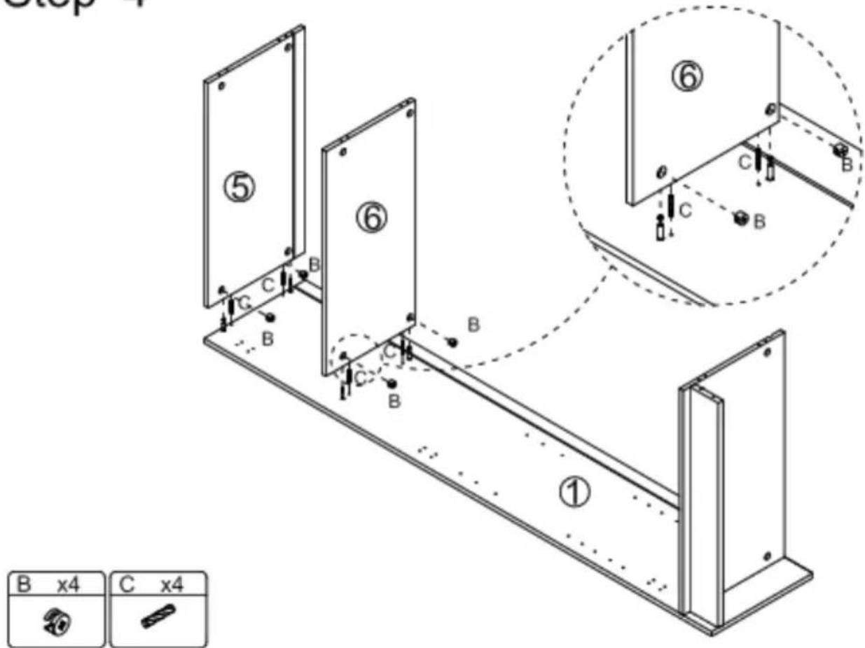
text_image
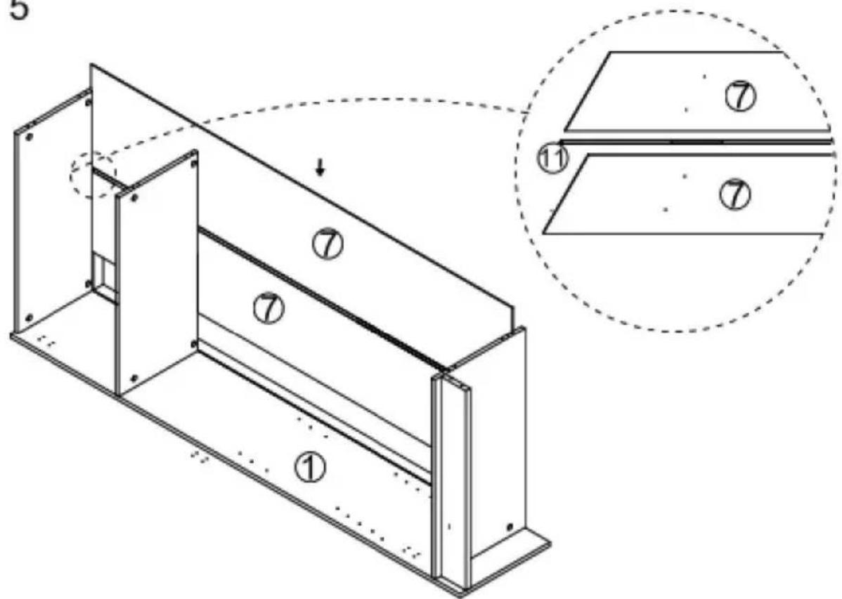
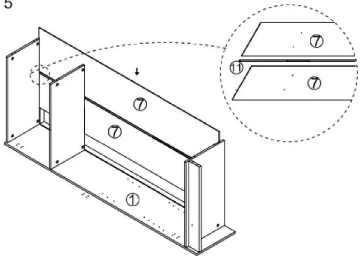
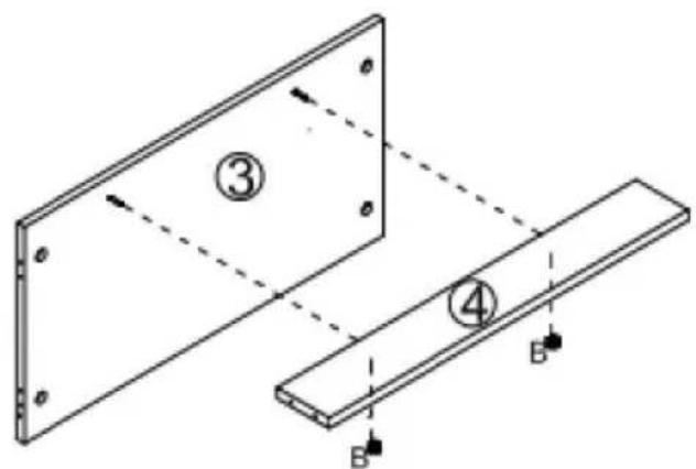
Step ① ② ③ ④ ⑤ ⑥ ⑦ B x4 C x4Step 5
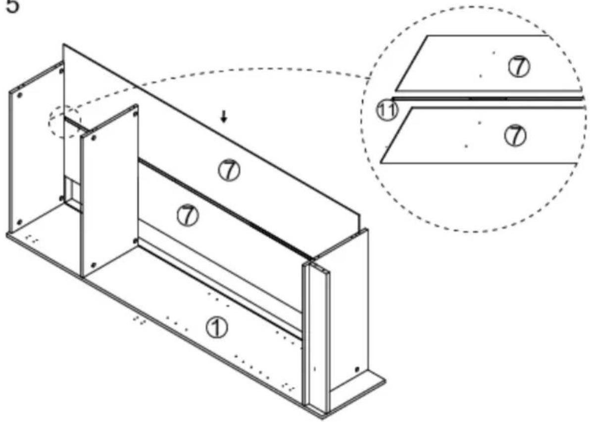
text_image
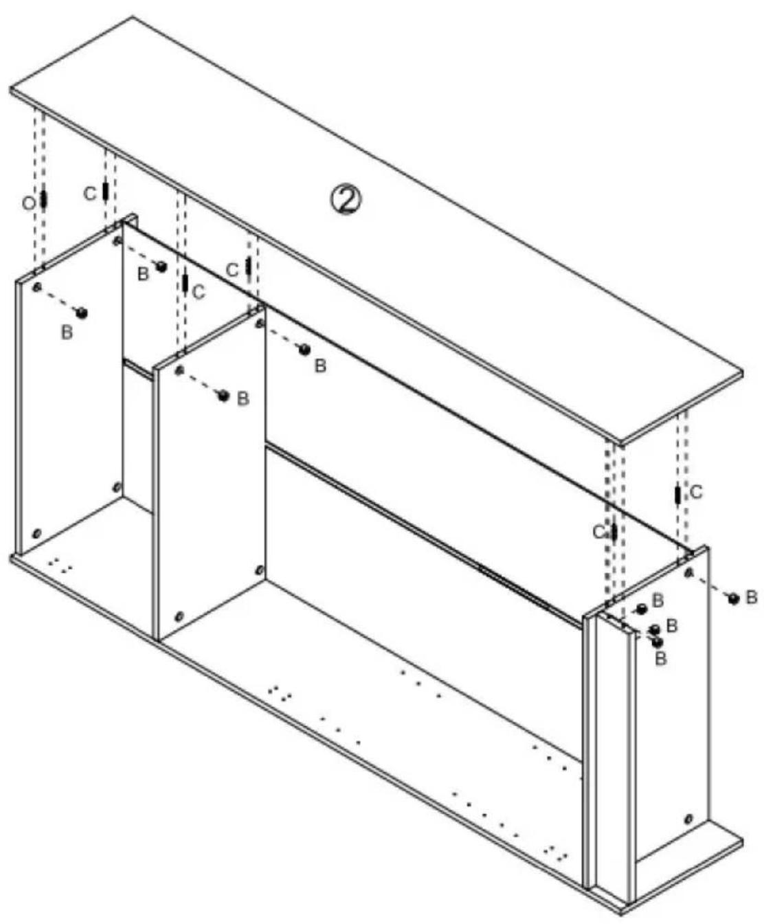
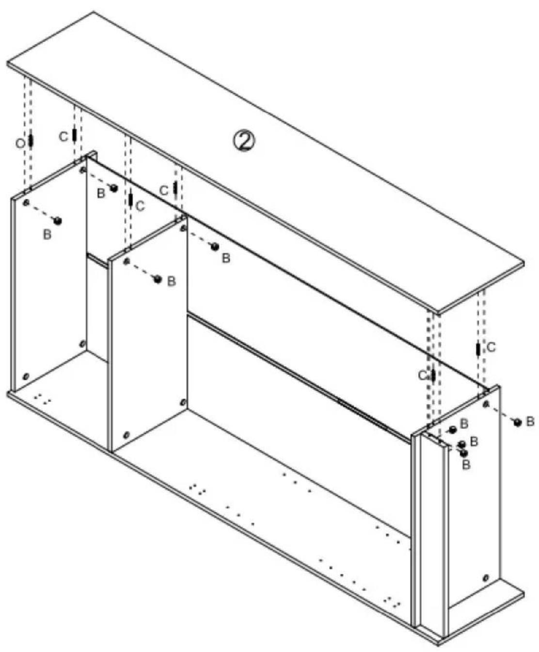
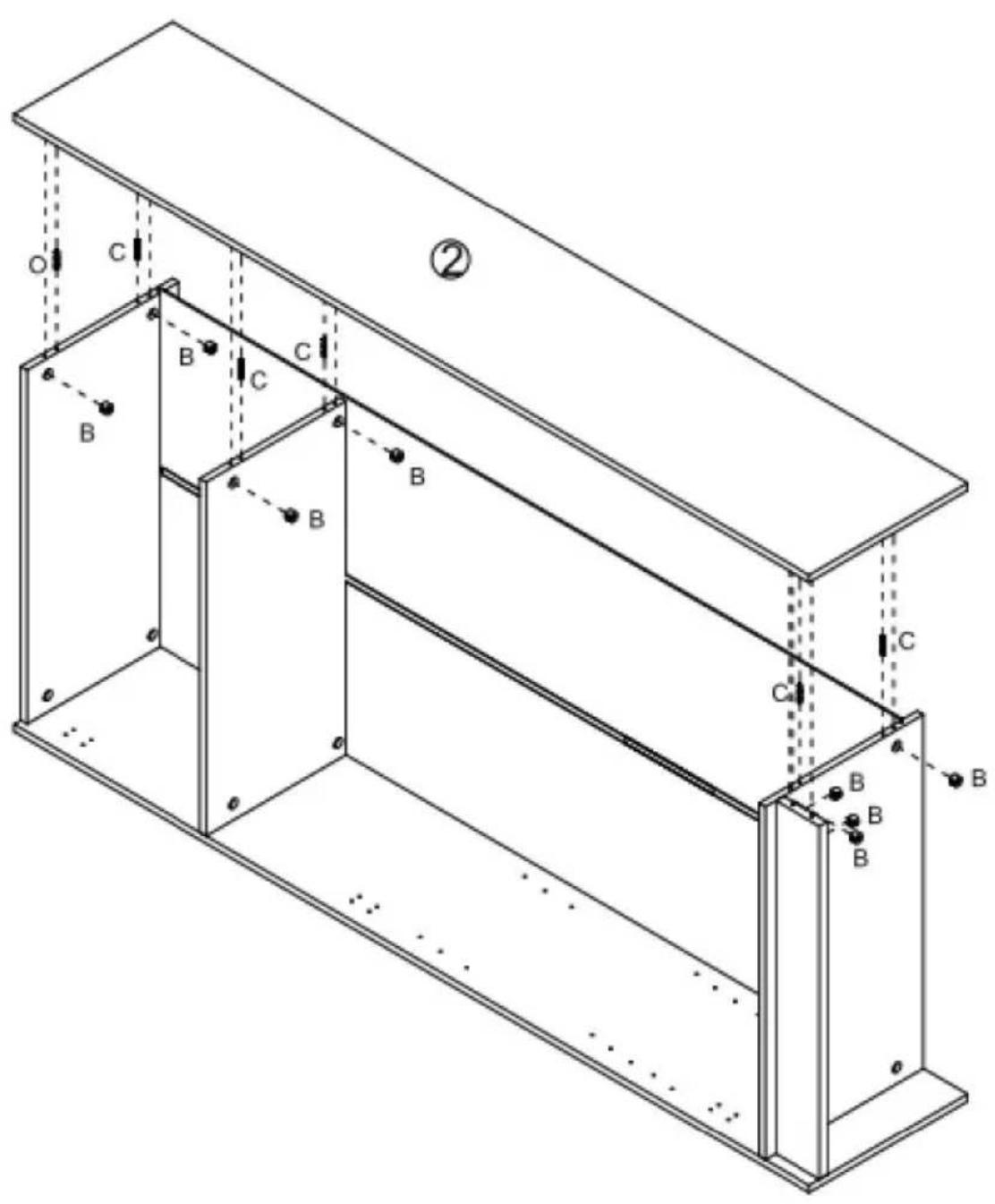
Technical diagram of a structural frame assembly with numbered components and an inset showing cross-sections labeled ①, ⑦, and ⑪.Step 6

text_image
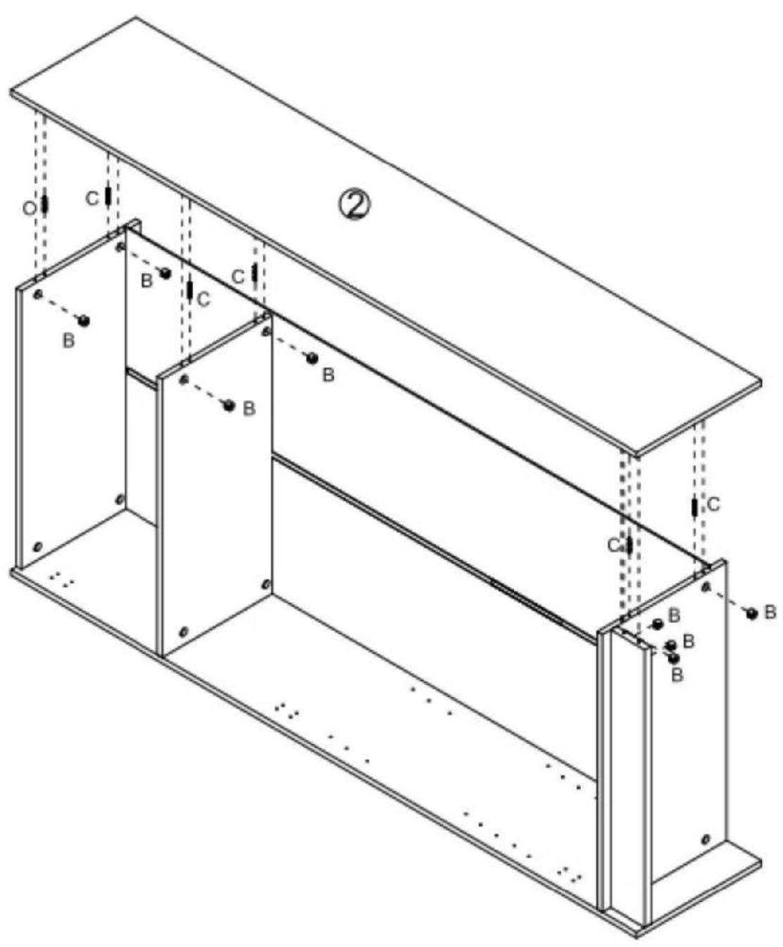
Technical diagram of a structural frame with labeled components and directional arrows indicating motion or force vectors.| B x8[08C8] | C x6 |
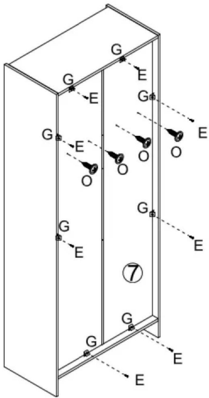
Step 7
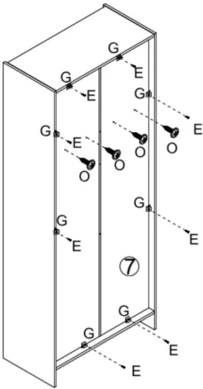
text_image
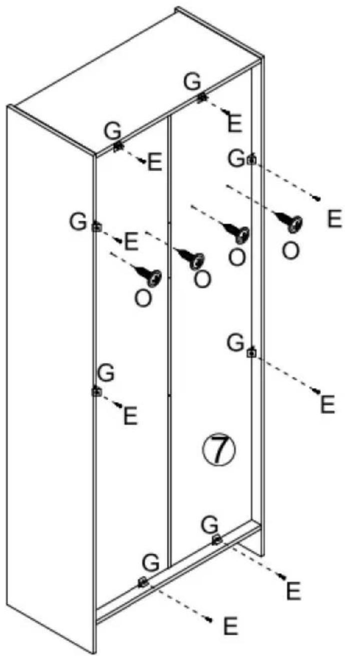
G E G E O O G E G E ⑦ G E E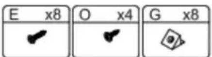
text_image
E x8 O x4 G x8Step 8
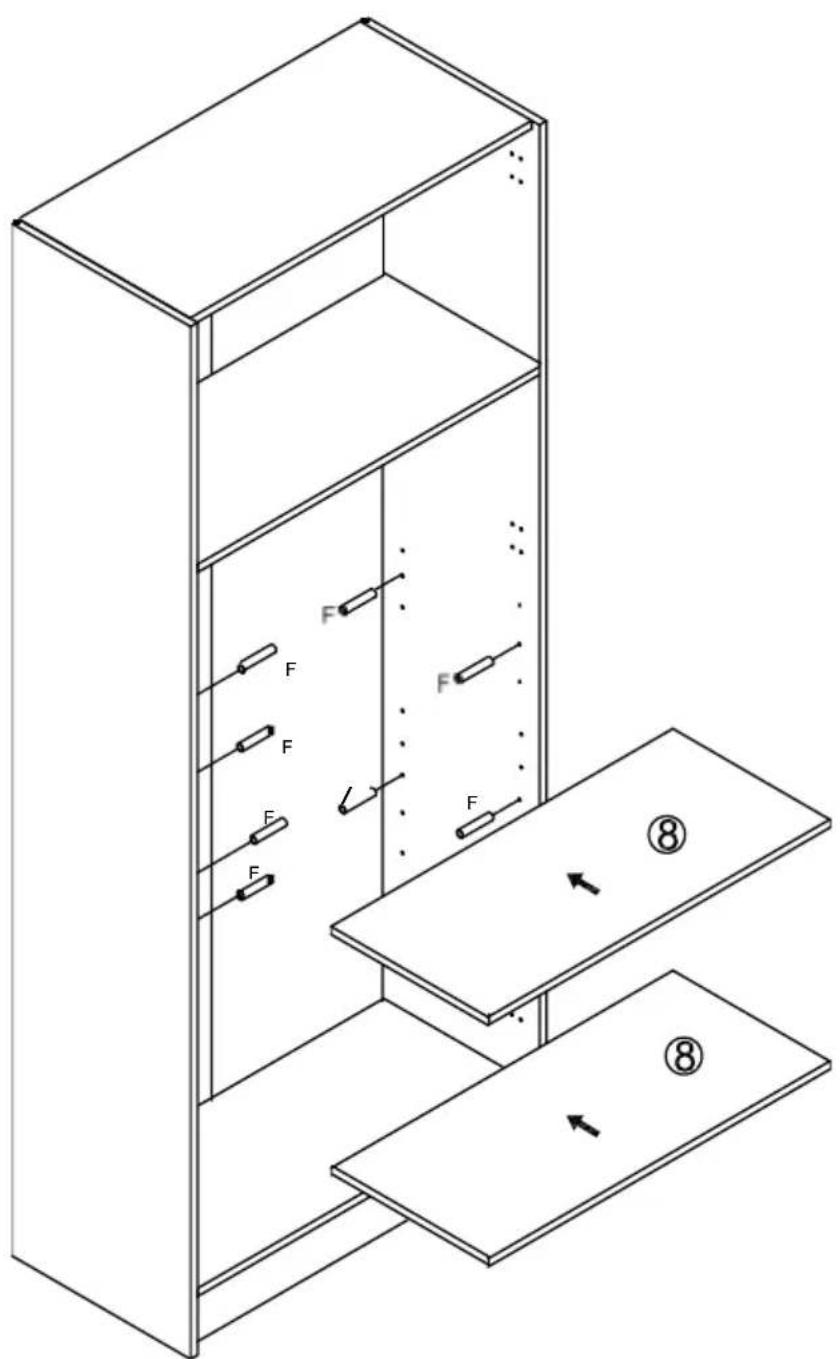
Notice: please adjust the height of the laminate according to the usage needs
text_image
Technical diagram of a multi-level cabinet with labeled force indicators (F) and numbered compartments (⑧), illustrating mechanical or electrical assembly.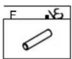
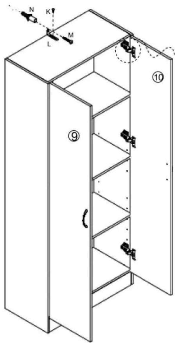
Step 9
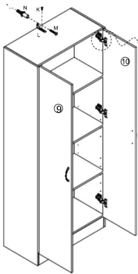
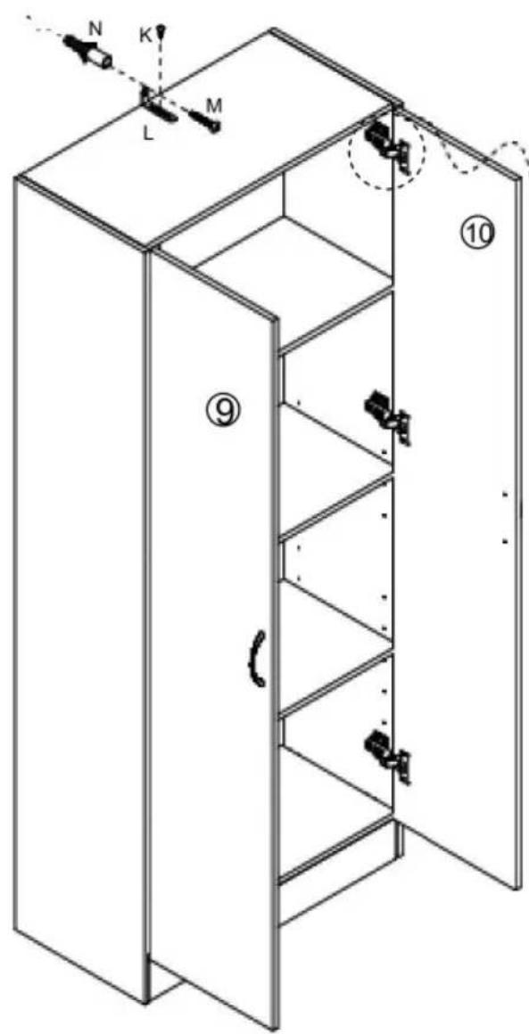
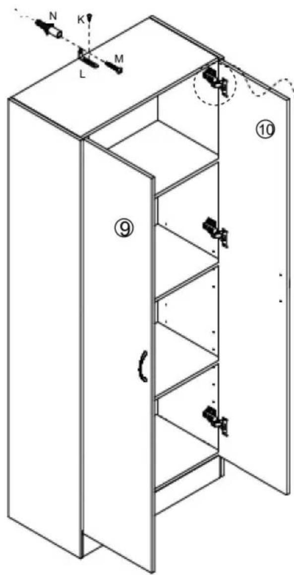
Attention: An anti tipping device must be installed to securely secure the product to the wall (Ensure the reliability of the wall itself).
text_image
N K L M ⑨ ⑩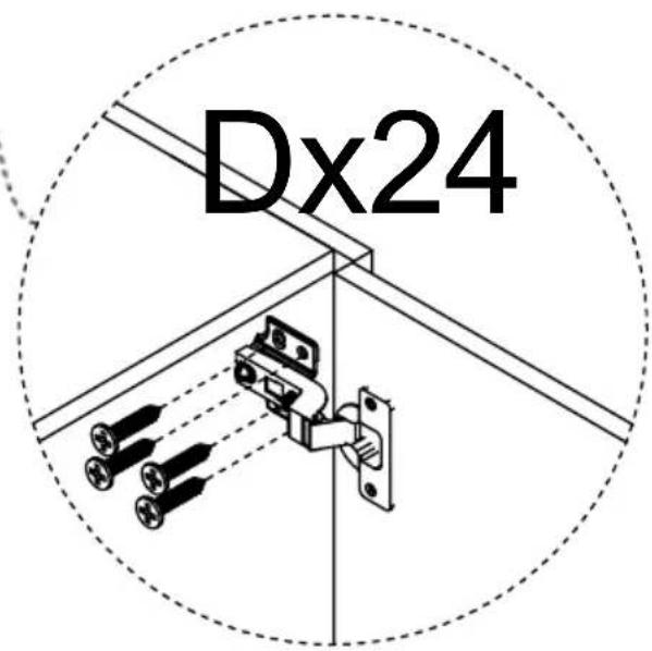
text_image
Dx24| K x1 | L x1 | M x1 | D x24 | N x1 |
- wipe with a Soft, dry cloth. Never use an abrasive cleanser or harsh pad. Do clean with water or other liquids.
- Be sure to keep the product dry
- children are not allowed to wipe the product to avoid tipping and falling inju
- RegularIY adding industrial grease to the door spindle and drawer slide can reduce noise and extend service life.
TIPS:
- Adding Pvc pads for easy cleaning
sanve n Te c h nolo Ltd.y
Address: suite 25 0 , 9 1 66 Anaheim place , Rancho cucamonga , CA9
VEVOR®
TOUGH TOOLS, HALF PRICE
Technical Support and E-warranty certificate www.vevor.com/support
VEVOR®
TOUGH TOOLS, HALF PRICE
natural_image
Line drawing of a two-decker cabinet with a handle and door (no text or symbols)NEED HELP? CONTACT US!
Have product questions? Need technical support? Please feel free to contact us:
Technical Support and E-Warranty Certificate www.vevor.com/support
PARAMÈTRES DU PRODUIT
text_image
Technical diagram of a multi-level building structure with numbered components, likely for architectural or engineering reference.
text_image
A x18 B x18 C x12 D x36 E x8 F x8 G x8 H x2 I x4 J x6 K x1 L x1 M x1 N x1 O x4 4x30mm 4x35mm 4x30mm 3x12mmNote: the quantity of parts shown in the manual is the actual usage and the unused parts are spare parts.
Step 1
text_image
Technical diagram showing nine sequential steps of a mechanical or structural assembly with labeled components (A, D, J) and numbered sections (①–⑩)
text_image
A x18 J x6 D x12 H x2 I x4Step 2
text_image
Technical diagram showing two structural components with labeled parts and directional arrows indicating motion or force.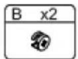
Step 3
text_image
Technical diagram showing a 3D mechanical assembly with labeled components and directional arrows indicating motion or force.| [Y 4] | C x2 |
Step 4
text_image
Step ① ⑤ ⑥ ⑥ B x4 C x4Step 5
text_image
Technical diagram of a structural frame assembly with numbered components and an inset showing cross-sections labeled ①, ⑦, and ⑪.Step 6
text_image
Technical diagram of a structural frame with labeled components and directional arrows indicating motion or force vectors.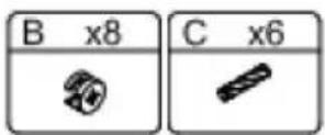
Step 7
text_image
G E G E O O O G E G E ⑦ G E E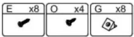
text_image
E x8 O x4 G x8Step 8
text_image
Technical diagram of a multi-level cabinet with labeled force indicators (F) and numbered compartments (⑧), illustrating mechanical or electrical assembly.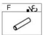
Step 9
Attention: An anti tipping device must be installed to securely secure the product to the wall (Ensure the reliability of the wall itself).
text_image
Technical diagram of a cabinet with labeled parts and directional indicators, including numbered components ⑨ and ⑩.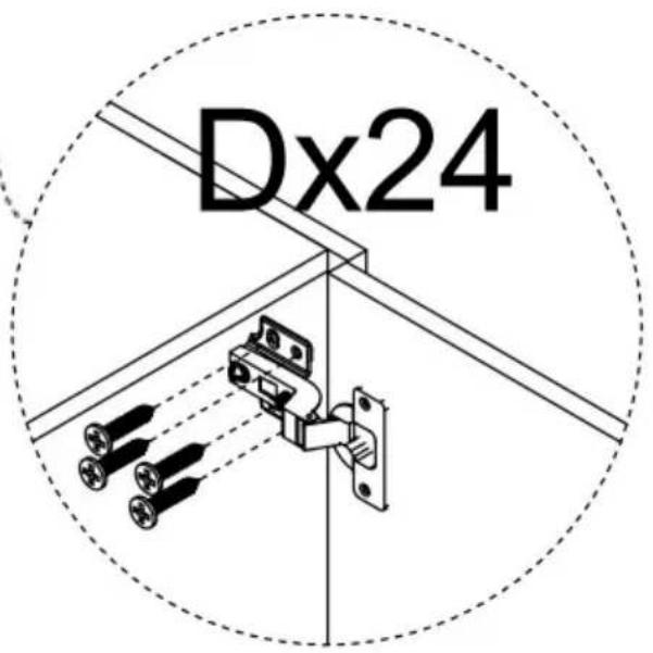
text_image
Dx24| K x1 | L x1 | M x1 | D x24 | N x1 |
natural_image
Line drawing of a two-decker cabinet with a handle and door (no text or symbols)NEED HELP? CONTACT US!
Have product questions? Need technical support? Please feel free to contact us:
Technical Support and E-Warranty Certificate www.vevor.com/support
text_image
Technical diagram of a multi-level building structure with numbered components, likely for architectural or engineering reference.
text_image
A x18 B x18 C x12 D x36 E x8 F x8 G x8 H x2 I x4 J x6 K x1 L x1 M x1 N x1 O x4 4x30mm 4x35mm 4x30mm 3x12mmNote: the quantity of parts shown in the manual is the actual usage and the unused parts are spare parts.
Step 1
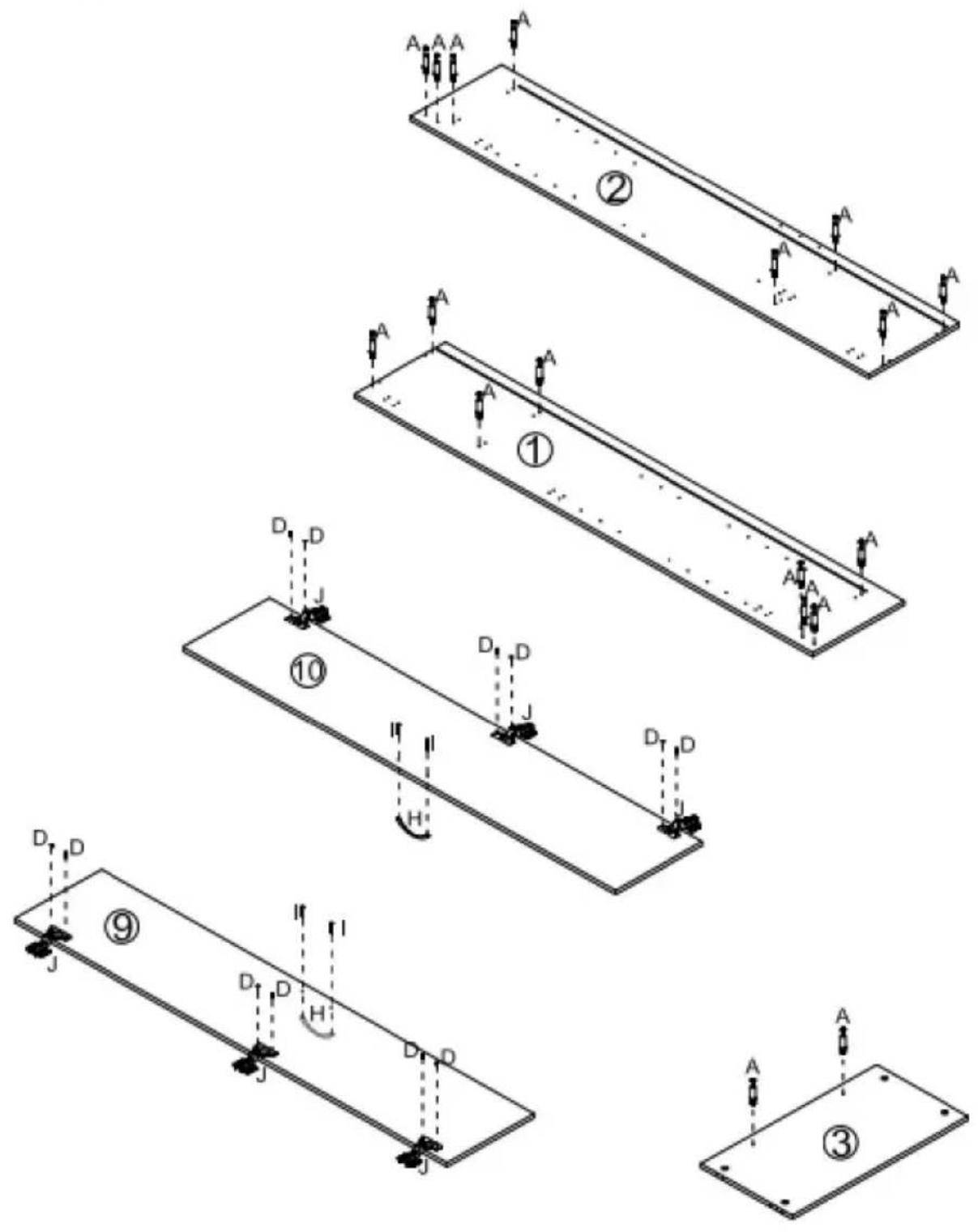
text_image
Technical diagram showing nine sequential steps of a mechanical or structural assembly with labeled components (A, D, J) and numbered sections (①–⑩)
text_image
A x18 J x6 D x12 H x2 I x4Step 2
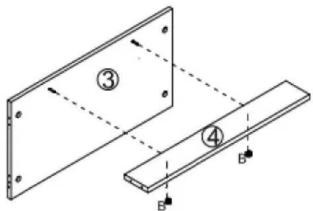
text_image
Technical diagram showing two structural components with labeled parts and directional arrows indicating motion or force.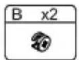
Step 3

text_image
Technical diagram showing a 3D mechanical assembly with labeled components and directional arrows indicating motion or force.| [7 Y] | C x2 |
Step 4
text_image
Step ① ⑤ ⑥ ⑥ B x4 C x4Step 5
text_image
Technical diagram of a structural frame assembly with numbered components and an inset showing cross-sections labeled ①, ⑦, and ⑪.Step 6
text_image
Technical diagram of a structural frame with labeled components and directional arrows indicating motion or force vectors.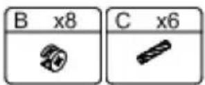
Step 7
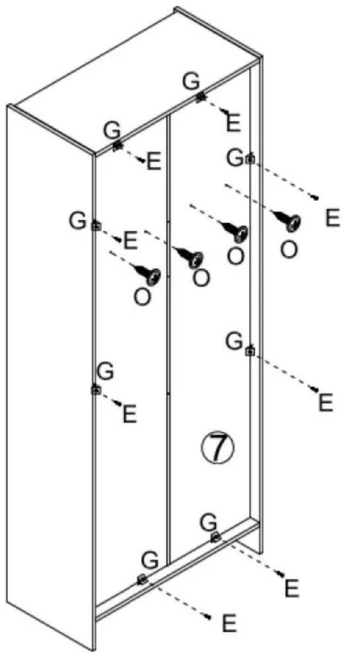
text_image
G E G E O O O G E G E ⑦ G E G E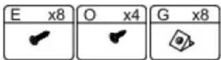
text_image
E x8 O x4 G x8Step 8
text_image
Technical diagram of a multi-level cabinet with labeled force indicators (F) and numbered compartments (⑧), illustrating mechanical or electrical assembly.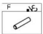
Step 9
Attention: An anti tipping device must be installed to securely secure the product to the wall (Ensure the reliability of the wall itself).
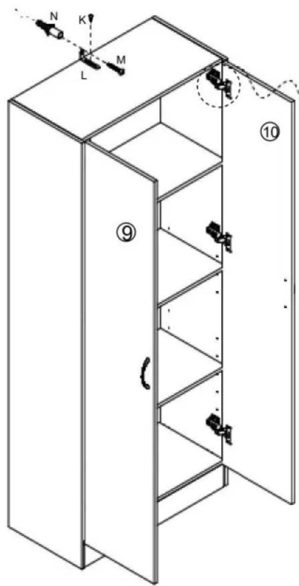
text_image
Technical diagram of a cabinet with labeled parts and directional indicators, including numbered components ⑨ and ⑩.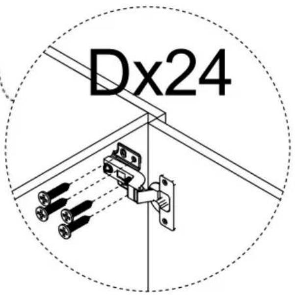
text_image
Dx24| K x1 | L x1 | M x1 | D x24 | N x1 |
natural_image
Line drawing of a two-decker cabinet with a handle and side panel (no text or symbols)NEED HELP? CONTACT US!
Have product questions? Need technical support? Please feel free to contact us:
Technical Support and E-Warranty Certificate www.vevor.com/support
text_image
Technical diagram of a multi-level building structure with numbered components, likely for architectural or engineering reference.
text_image
A x18 B x18 C x12 D x36 E x8 F x8 G x8 H x2 I x4 J x6 K x1 L x1 M x1 N x1 O x4 4x30mm 4x35mm 4x30mm 3x12mmNote: the quantity of parts shown in the manual is the actual usage and the unused parts are spare parts.
Step 1
text_image
Technical diagram showing nine sequential steps of a mechanical or structural assembly with labeled components (A, D, J) and numbered sections (①–⑩)
text_image
A x18 J x6 D x12 H x2 I x4Step 2
text_image
Technical diagram showing two structural components with labeled parts and directional arrows indicating motion or force.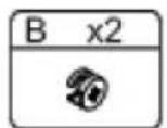
Step 3
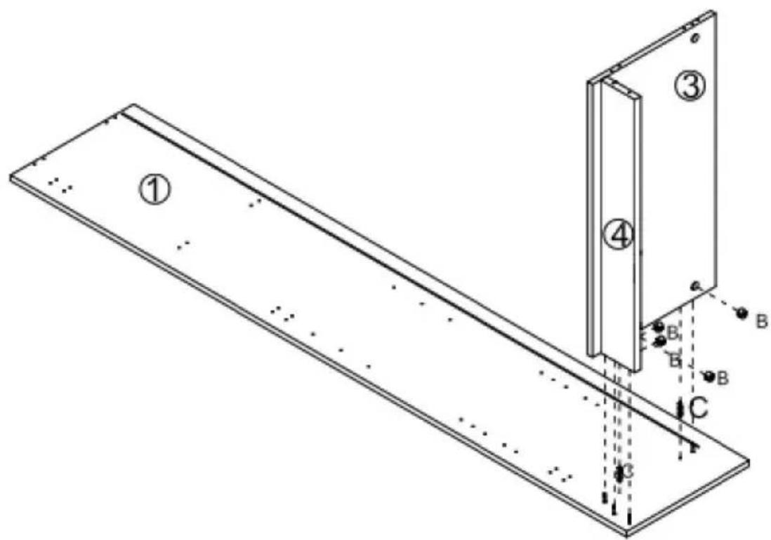
text_image
Technical diagram showing a 3D mechanical assembly with labeled components and directional arrows indicating motion or force.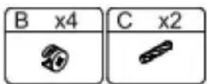
Step 4
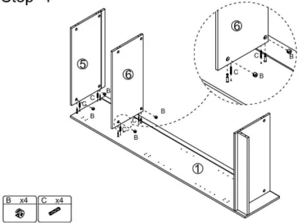
text_image
Step ① ⑤ ⑥ ⑥ B x4 C x4Step 5
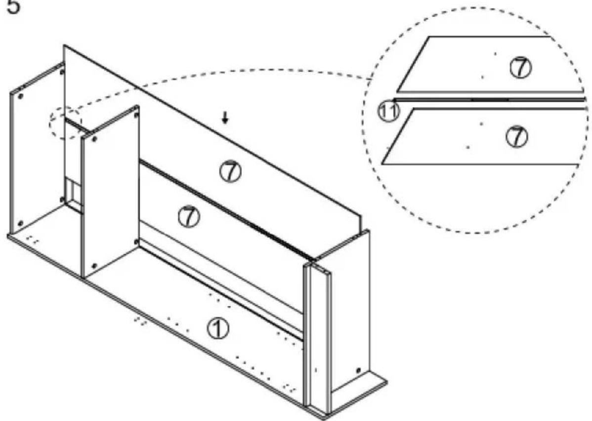
text_image
Technical diagram of a structural frame assembly with numbered components and an inset showing cross-sections labeled ①, ⑦, and ⑪.Step 6
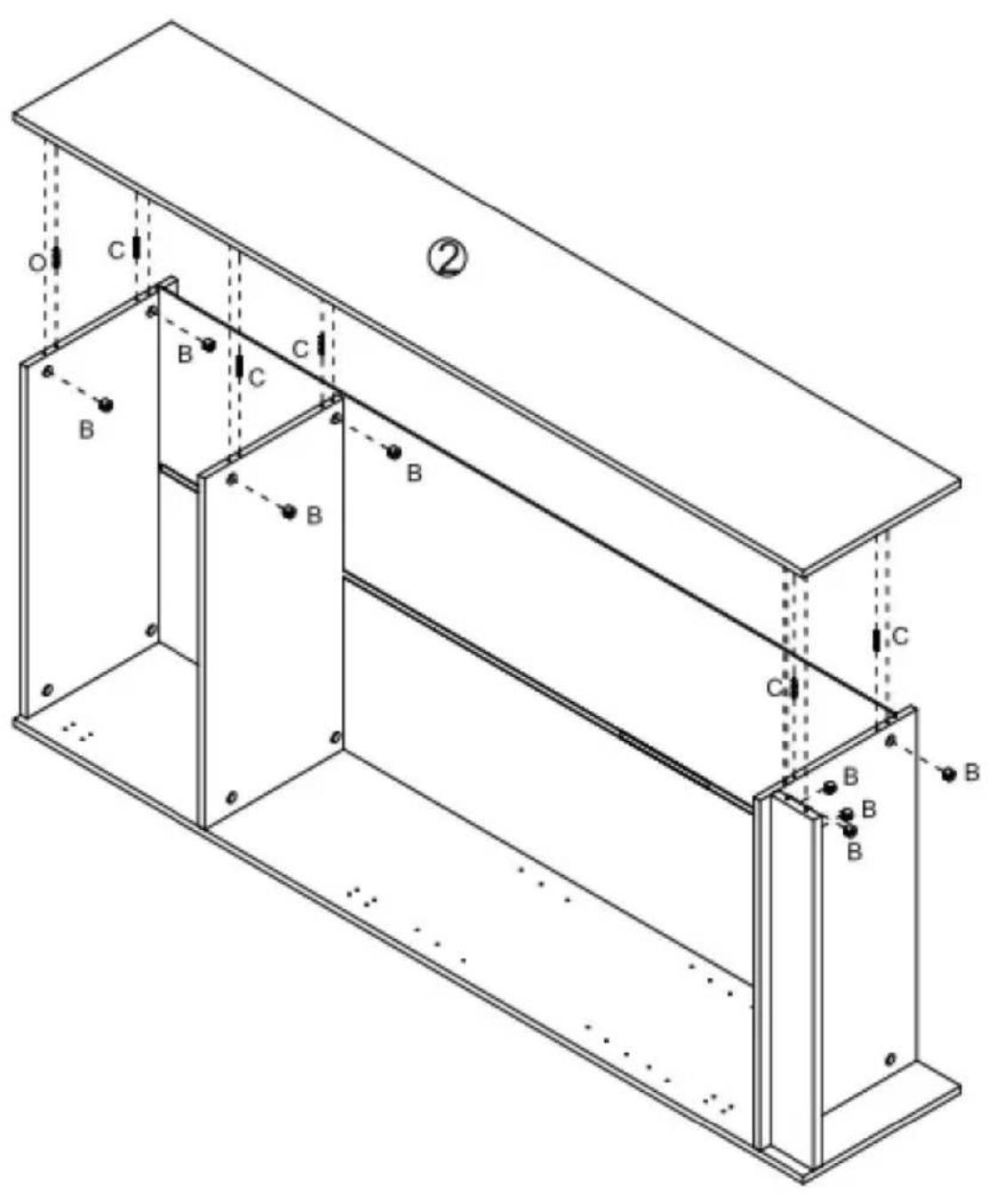
text_image
Technical diagram of a structural frame with labeled components and directional arrows indicating motion or force vectors.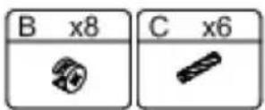
Step 7
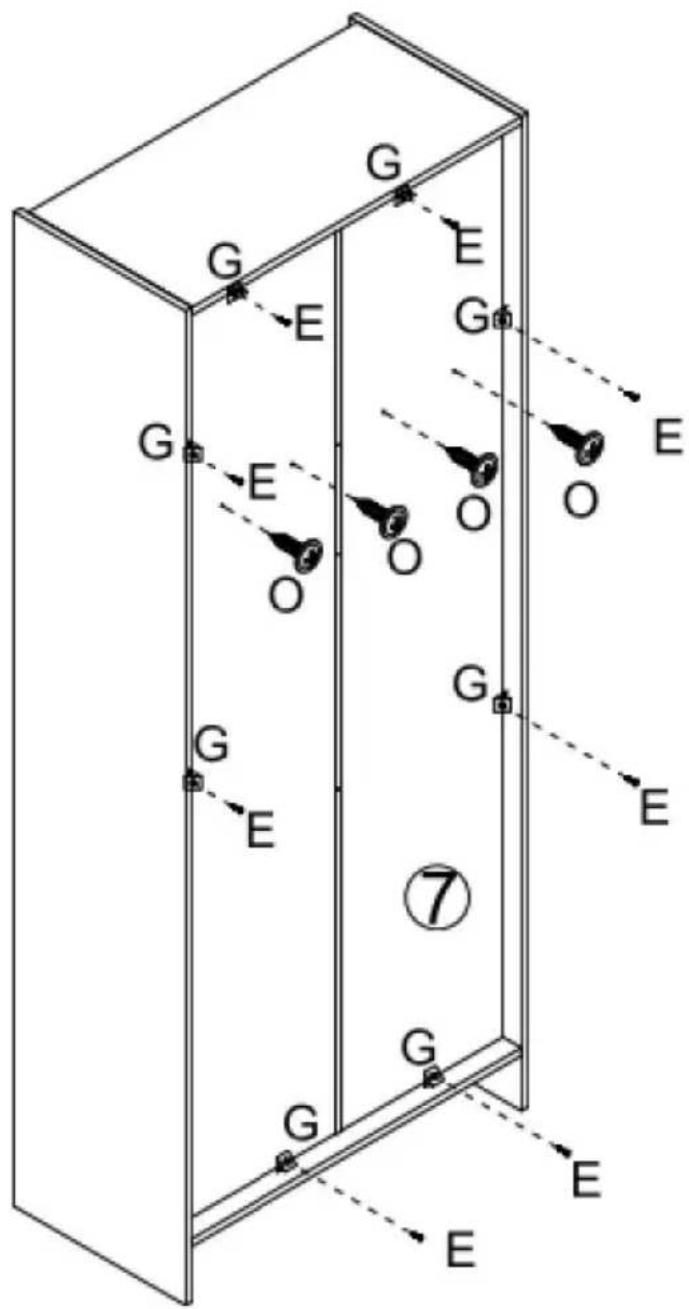
text_image
G E G E O O O G E G E ⑦ G E G E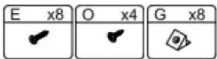
text_image
E x8 O x4 G x8Step 8
text_image
Technical diagram of a multi-level cabinet with labeled force indicators (F) and numbered compartments (⑧), illustrating mechanical or electrical assembly.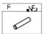
Step 9
Attention: An anti tipping device must be installed to securely secure the product to the wall (Ensure the reliability of the wall itself).
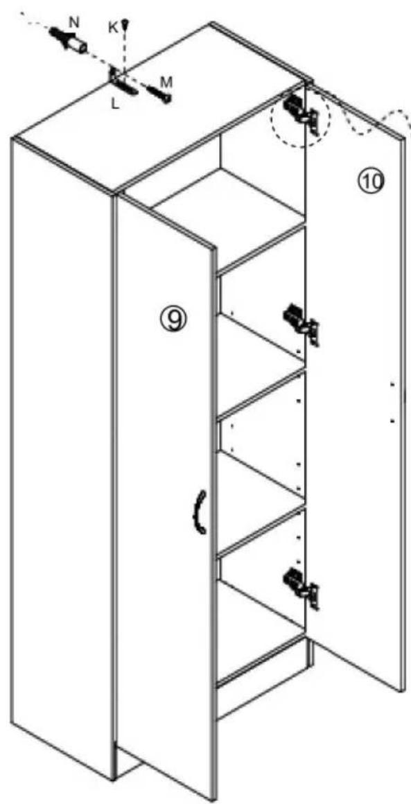
text_image
N K L M ⑨ ⑩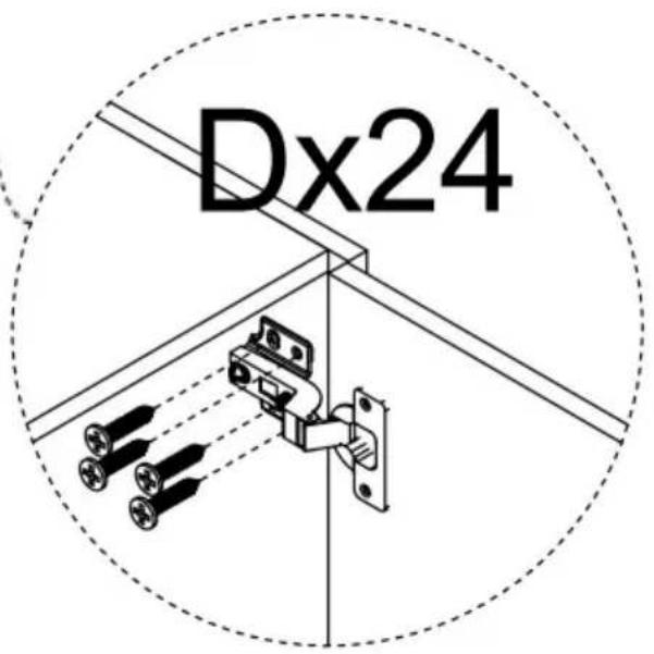
text_image
Dx24| K x1 | L x1 | M x1 | D x24 | N x1 |
natural_image
Line drawing of a two-decker cabinet with a handle and door (no text or symbols)NEED HELP? CONTACT US!
Have product questions? Need technical support? Please feel free to contact us:
Technical Support and E-Warranty Certificate www.vevor.com/support
text_image
Technical diagram of a multi-level mechanical or architectural structure with numbered components, likely for engineering or architectural reference.
text_image
A x18 B x18 C x12 D x36 E x8 F x8 G x8 H x2 I x4 J x6 K x1 L x1 M x1 N x1 O x4 4x30mm 4x35mm 4x30mm 3x12mmNote: the quantity of parts shown in the manual is the actual usage and the unused parts are spare parts.
Step 1
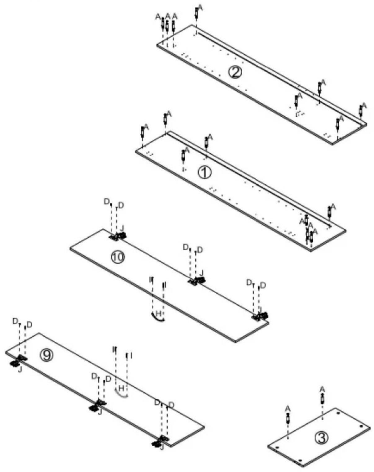
text_image
Technical diagram showing nine sequential steps of a mechanical or structural assembly with labeled components (A, D, J) and numbered sections (①–⑩)
text_image
A x18 J x6 D x12 H x2 I x4Step 2
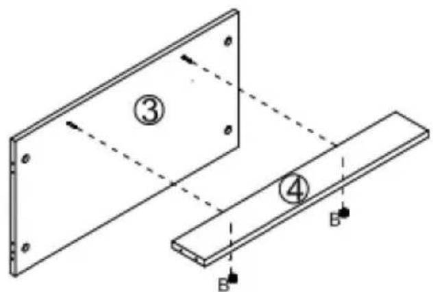
text_image
Technical diagram showing two structural components with labeled parts and directional arrows indicating motion or force.
Step 3
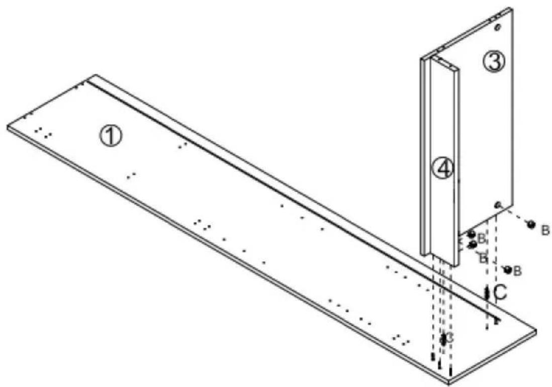
text_image
Technical diagram showing a 3D mechanical assembly with labeled components and directional arrows indicating motion or force. [E_ Y] Y] | C x2 |
Step 4
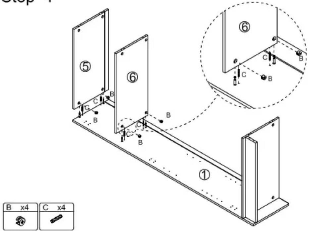
text_image
Step ① ⑤ ⑥ ⑥ B x4 C x4Step 5
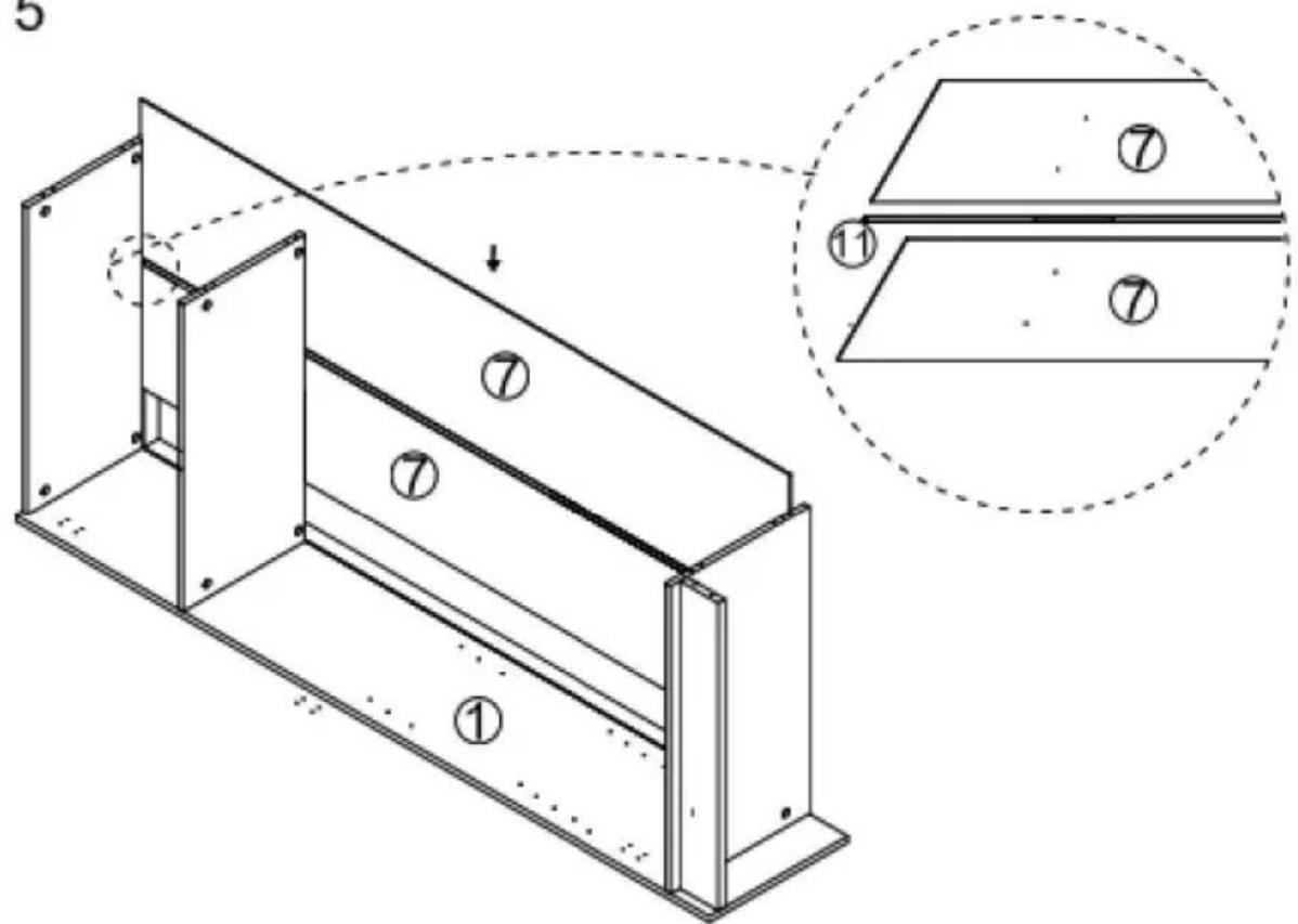
text_image
Technical diagram of a structural frame assembly with numbered components and an inset showing cross-sections labeled ①, ⑦, and ⑪.Step 6
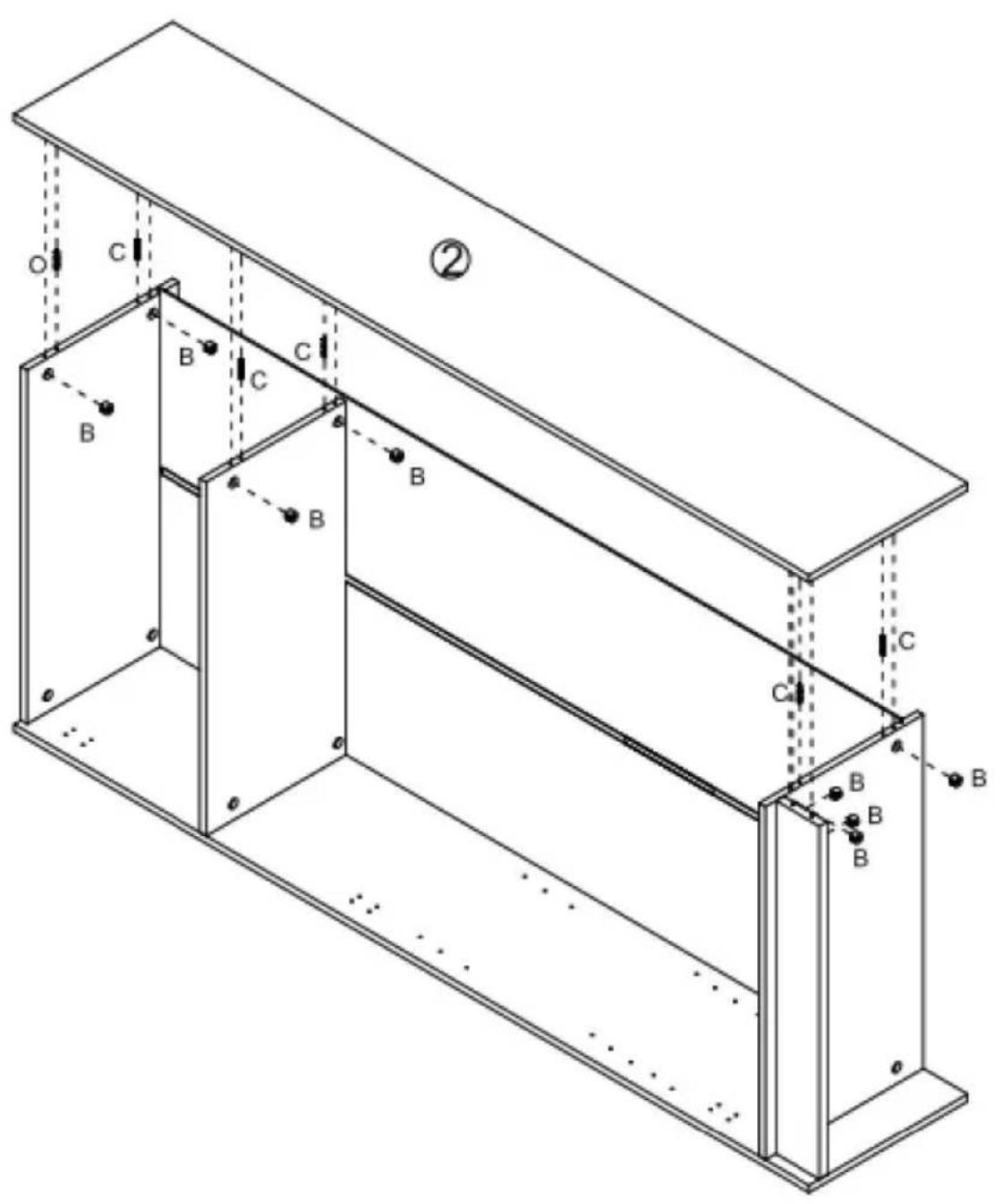
text_image
Technical diagram of a structural frame with labeled components and directional arrows indicating motion or force vectors.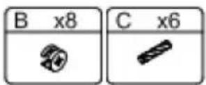
Step 7

text_image
G E G E O O O G E G E ⑦ G E E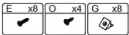
text_image
E x8 O x4 G x8Step 8
text_image
Technical diagram of a multi-level cabinet with labeled force indicators (F) and numbered compartments (⑧), illustrating mechanical or electrical assembly.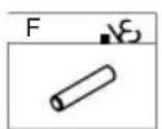
Step 9
Attention: An anti tipping device must be installed to securely secure the product to the wall (Ensure the reliability of the wall itself).
text_image
Technical diagram of a cabinet with labeled parts and directional indicators (N, K, L, M)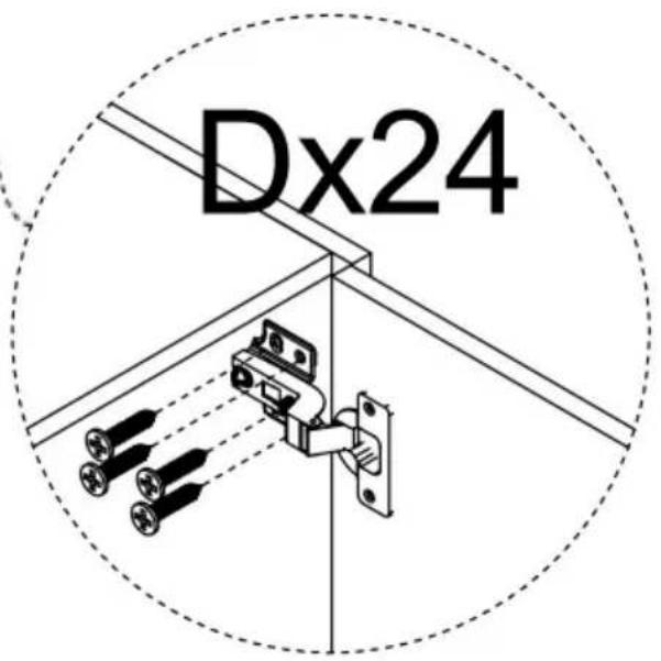
text_image
Dx24| K x1 | L x1 | M x1 | D x24 | N x1 |
LIMPIEZA Y ALMACENAMIENTO
natural_image
Line drawing of a two-decker cabinet with a handle and door (no text or symbols)NEED HELP? CONTACT US!
Have product questions? Need technical support? Please feel free to contact us:
Technical Support and E-Warranty Certificate www.vevor.com/support
text_image
Technical diagram of a multi-level building structure with numbered components, likely for architectural or engineering reference.
text_image
A x18 B x18 C x12 D x36 E x8 F x8 G x8 H x2 I x4 J x6 K x1 L x1 M x1 N x1 O x4 4x30mm 4x35mm 3x12mmNote: the quantity of parts shown in the manual is the actual usage and the unused parts are spare parts.
Step 1
text_image
Technical diagram showing nine sequential steps of a mechanical or structural assembly with labeled components (A, D, J) and numbered sections (①–⑩)
text_image
A x18 J x6 D x12 H x2 I x4Step 2
text_image
Technical diagram showing two structural components with labeled parts and directional arrows indicating motion or force.
Step 3
text_image
Technical diagram showing a 3D mechanical assembly with labeled components and directional arrows indicating motion or force.| [€T7ZA] 7] | C x2 |
Step 4
text_image
Step ① ⑤ ⑥ ⑥ B x4 C x4Step 5

text_image
Technical diagram of a structural frame assembly with numbered components and an inset showing cross-sections labeled ①, ⑦, and ⑪.Step 6
text_image
Technical diagram of a structural frame with labeled components and directional arrows indicating motion or force vectors.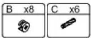
Step 7
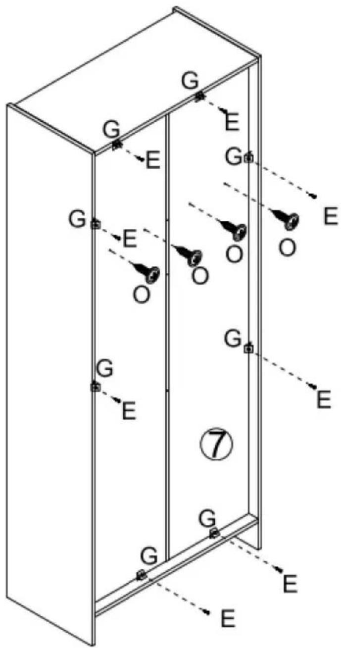
text_image
G E G E O O O G E G E ⑦ G E E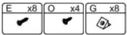
text_image
E x8 O x4 G x8Step 8
text_image
Technical diagram of a cabinet with labeled components and directional arrows indicating movement or assembly.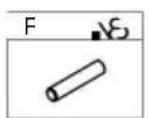
Step 9
Attention: An anti tipping device must be installed to securely secure the product to the wall (Ensure the reliability of the wall itself).
text_image
Technical diagram of a cabinet with labeled parts and directional indicators, including numbered components and motion arrows.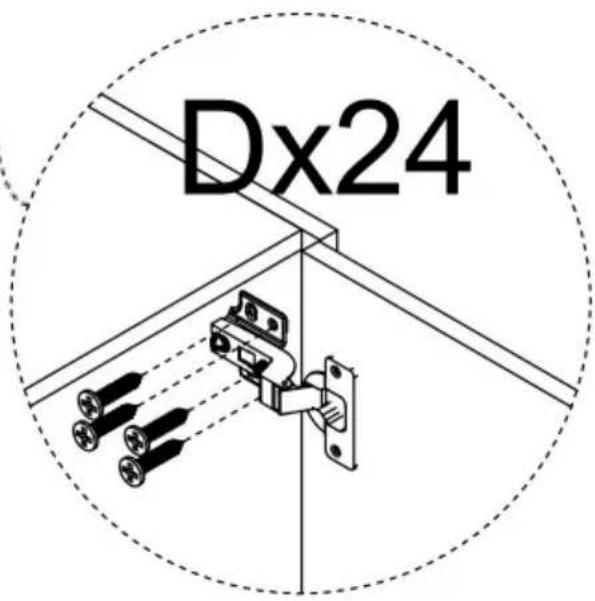
text_image
Dx24| K x1 | L x1 | M x1 | D x24 | N x1 |
CZYSZCZENIE I PRZECHOWYWANIE
, 9166Anaheim place, Rancho Cucamonga,
CA91 730
VEVOR®
TOUGH TOOLS, HALF PRICE
natural_image
Line drawing of a two-decker cabinet with a handle and side panel (no text or symbols)NEED HELP? CONTACT US!
Have product questions? Need technical support? Please feel free to contact us:
Technical Support and E-Warranty Certificate www.vevor.com/support
text_image
Technical diagram of a multi-level mechanical or architectural structure with numbered components, likely for engineering or architectural reference.
text_image
A x18 B x18 C x12 D x36 E x8 F x8 G x8 H x2 I x4 J x6 K x1 L x1 M x1 N x1 O x4 4x30mm 4x35mm 4x30mm 3x12mmNote: the quantity of parts shown in the manual is the actual usage and the unused parts are spare parts.
Step 1
text_image
Technical diagram showing nine sequential steps of a mechanical or structural assembly with labeled components (A, D, J) and numbered sections (①–⑩)
text_image
A x18 J x6 D x12 H x2 I x4Step 2
text_image
Technical diagram showing two structural components with labeled parts and directional arrows indicating motion or force.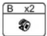
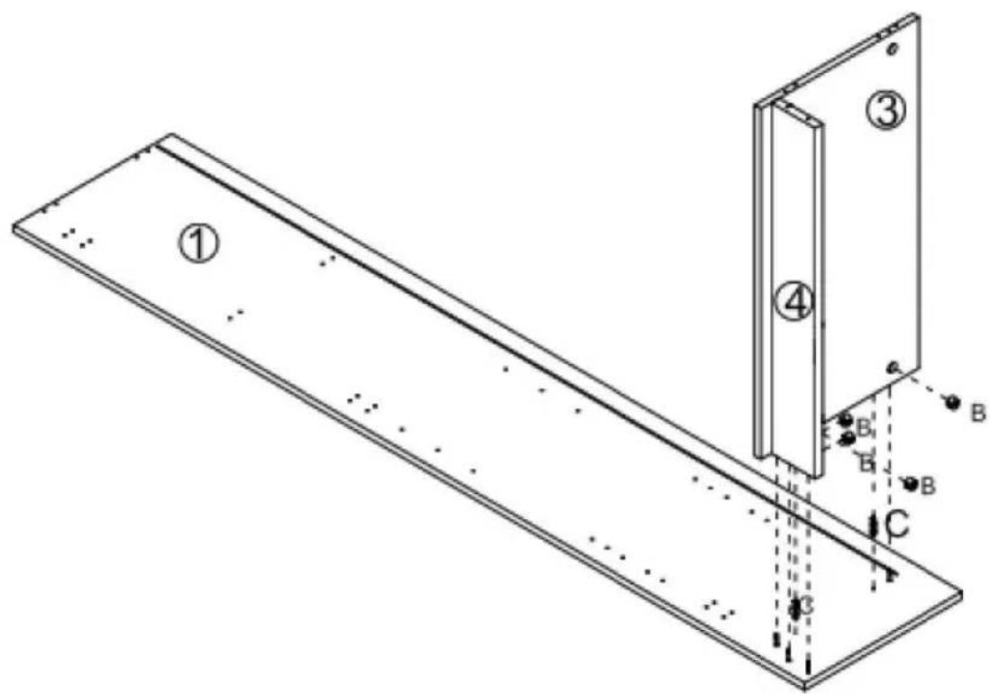
Step 3
text_image
Technical diagram showing a 3D mechanical assembly with labeled components and directional arrows indicating motion or force.| [C_{B06D}] | C x2 |
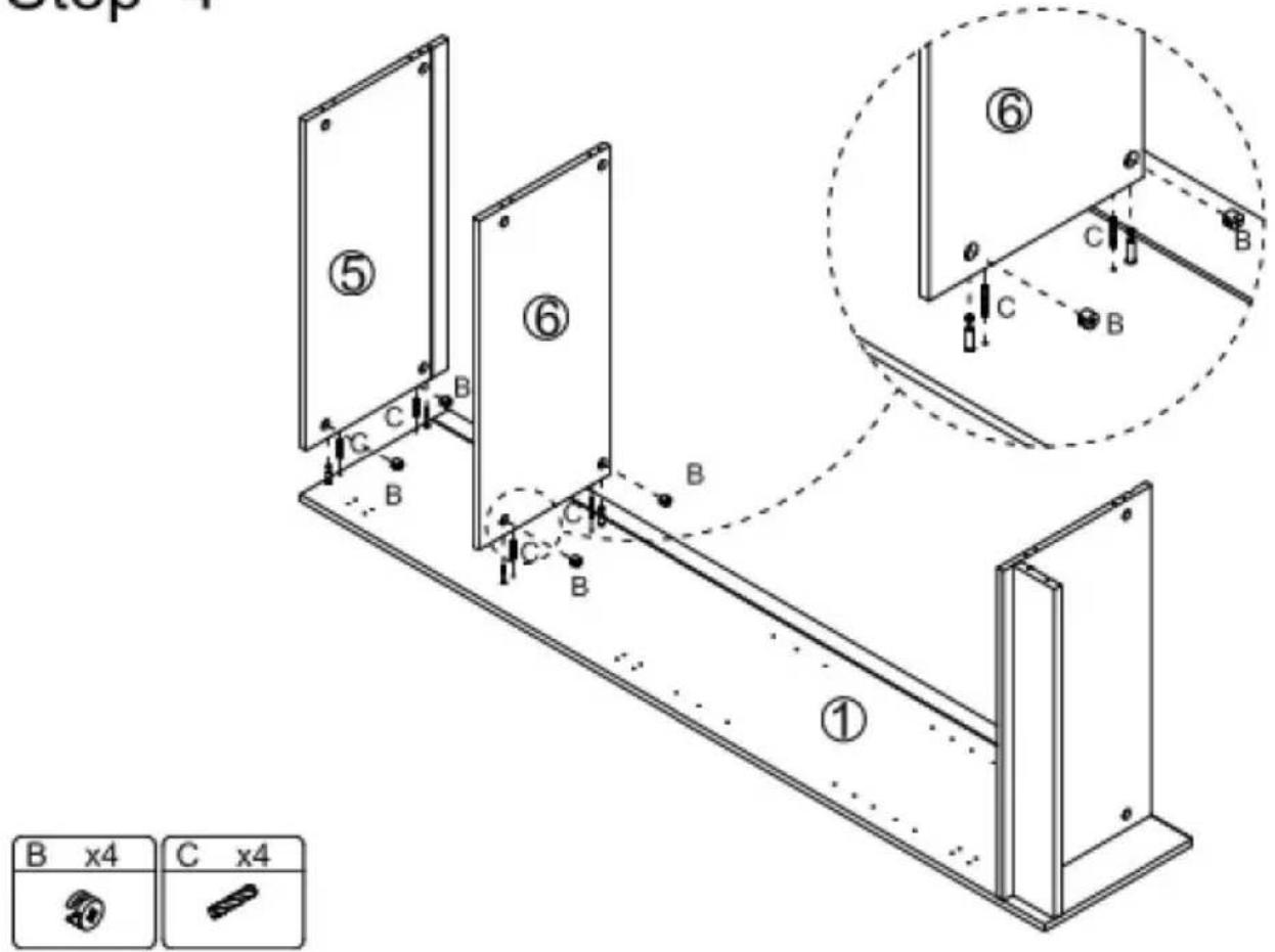
Step 4
text_image
Step ① ⑤ ⑥ ⑥ B x4 C x4Step 5
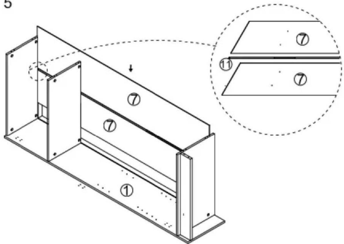
text_image
Technical diagram of a structural frame assembly with numbered components and an inset showing cross-sections labeled ①, ⑦, and ⑪.Step 6
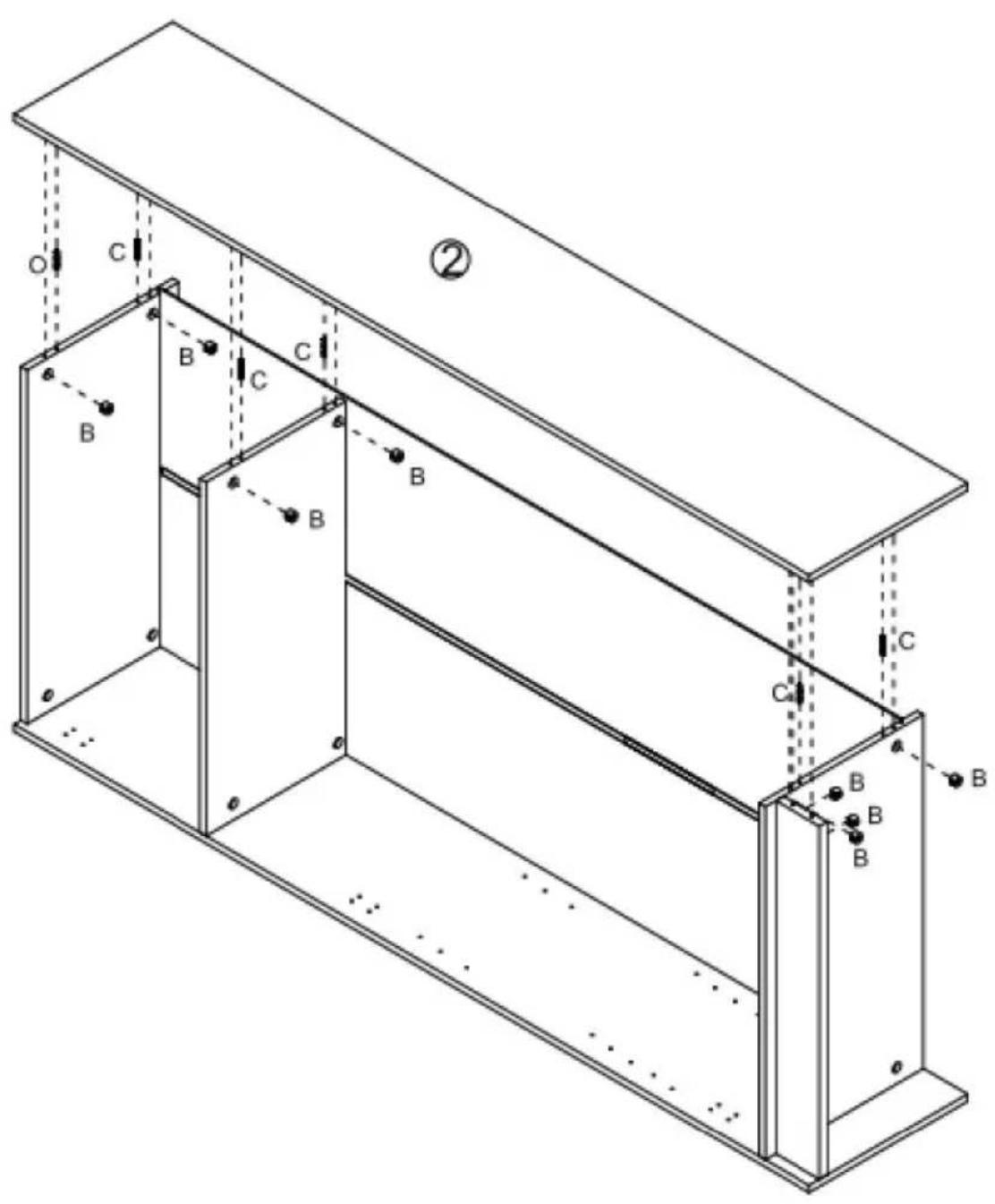
text_image
Technical diagram of a structural frame with labeled components and directional arrows indicating motion or force vectors.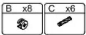
Step 7
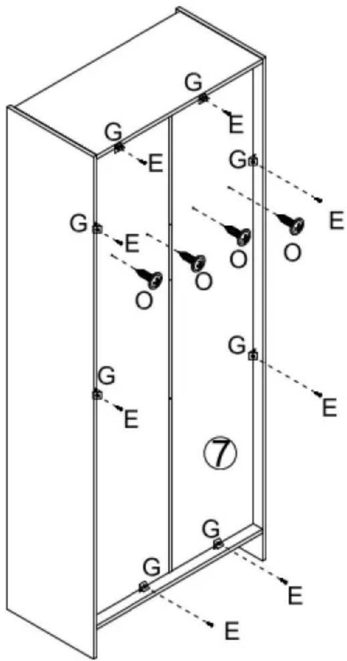
text_image
G E G E O O O G E G E ⑦ G E E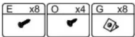
text_image
E x8 O x4 G x8Step 8
text_image
Technical diagram of a multi-level cabinet with labeled force indicators (F) and numbered compartments (⑧), illustrating mechanical or electrical assembly.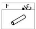
Step 9
Attention: An anti tipping device must be installed to securely secure the product to the wall (Ensure the reliability of the wall itself).

text_image
N K L M ⑩ ⑨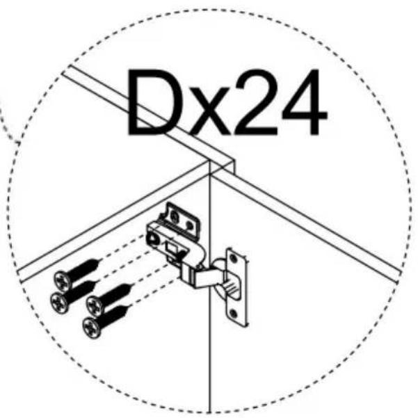
text_image
Dx24| K x1 | L x1 | M x1 | D x24 | N x1 |
REINIGING EN OPSLAG
natural_image
Line drawing of a two-decker cabinet with a handle and side panel (no text or symbols)NEED HELP? CONTACT US!
Have product questions? Need technical support? Please feel free to contact us:
Technical Support and E-Warranty Certificate www.vevor.com/support
text_image
Technical diagram of a multi-level building structure with numbered components, likely for architectural or engineering reference.
text_image
A x18 B x18 C x12 D x36 E x8 F x8 G x8 H x2 I x4 J x6 K x1 L x1 M x1 N x1 O x4 4x30mm 4x35mm 4x30mm 3x12mmNote: the quantity of parts shown in the manual is the actual usage and the unused parts are spare parts.
Step 1
text_image
Technical diagram showing nine sequential steps of a mechanical or structural assembly with labeled components (A, D, J) and numbered sections (①–⑩)
text_image
A x18 J x6 D x12 H x2 I x4Step 2
text_image
Technical diagram showing two structural components with labeled parts and directional arrows indicating motion or force.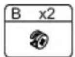
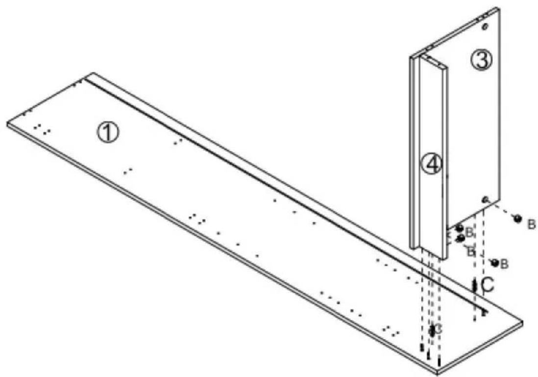
Step 3
text_image
Technical diagram showing a 3D mechanical assembly with labeled components and directional arrows indicating motion or force.| [2 4] | C x2 |
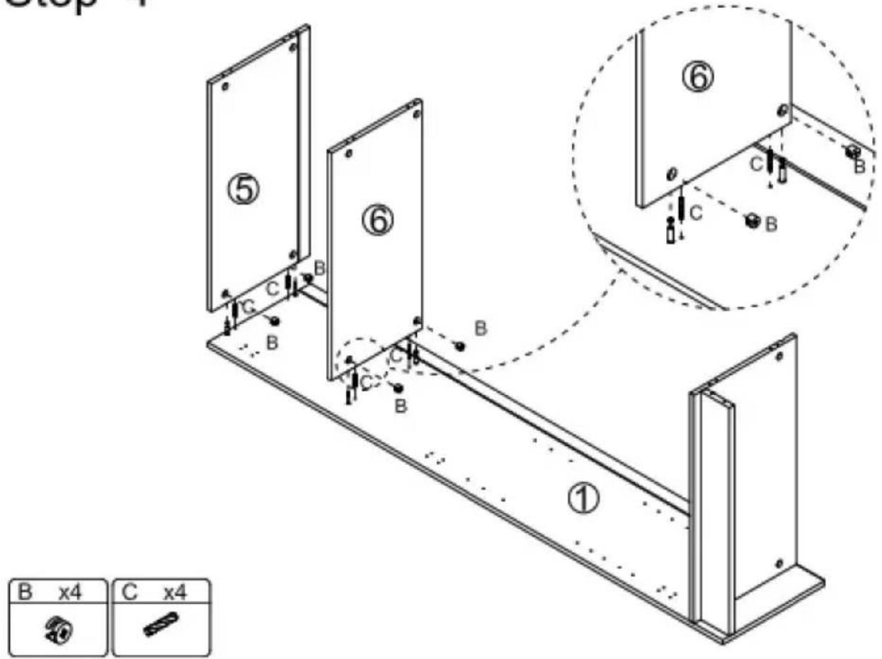
Step 4
text_image
Step ① ⑤ ⑥ ⑥ B x4 C x4Step 5
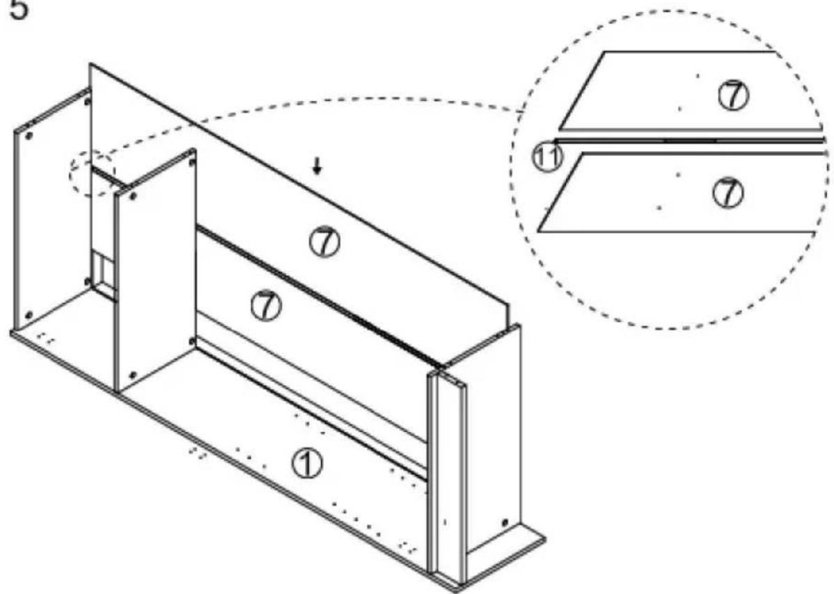
text_image
Technical diagram of a structural frame assembly with numbered components and an inset showing cross-sections labeled ①, ⑦, and ⑪.Step 6
text_image
Technical diagram of a structural frame with labeled components and directional arrows indicating motion or force vectors.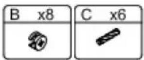
Step 7
text_image
G E G E O O O G E G E ⑦ G E E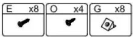
text_image
E x8 O x4 G x8Step 8
text_image
Technical diagram of a multi-level cabinet with labeled force indicators (F) and numbered compartments (⑧), illustrating mechanical or electrical assembly.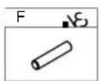
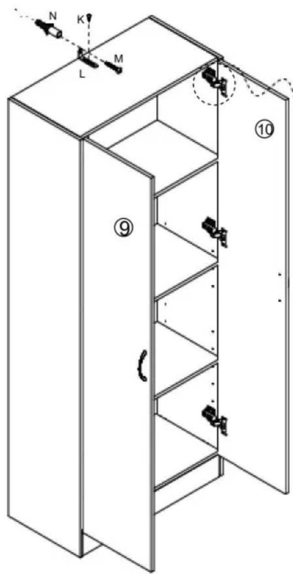
Step 9
Attention: An anti tipping device must be installed to securely secure the product to the wall (Ensure the reliability of the wall itself).
text_image
Technical diagram of a cabinet with labeled parts and directional indicators, including numbered components ⑨ and ⑩.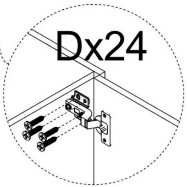
text_image
Dx24| K x1 | L x1 | M x1 | D x24 | N x1 |
RENGÖRING OCH FÖRVARING
Adress: svit 250, 9166Anaheim place, Rancho cucamonga, CA91 730
VEVOR®
TOUGH TOOLS, HALF PRICE
Technical Supp rboch E-garanticertifikat www vevor.
com/supp rt
0