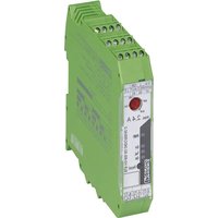
ELR H3-IES-SC-230AC/500AC-2 - Starter motor Phoenix Contact - Free user manual and instructions
Find the device manual for free ELR H3-IES-SC-230AC/500AC-2 Phoenix Contact in PDF.


| Product type | Hybrid motor starter |
| Brand / Model | Phoenix Contact ELR H3-IES-SC-230AC/500AC-2 |
| Reference | 2900568 |
| Control supply voltage | 230 V AC (50/60 Hz) |
| Control supply voltage range | 85 ... 253 V AC |
| Rated operational voltage | 500 V AC (50/60 Hz) |
| Rated load current (at 20 °C) | 0.18 ... 2.4 A |
| Line protection (recommended fuses) | 25 A gL/gG (cable ≤2.5 mm²), 16 A FF (device), 20 A motor circuit breaker |
| Dimensions (W x H x D) | 22.5 x 99 x 114.5 mm |
| Weight | Approx. 212 g |
| Protection degree | IP20 |
| Ambient temperature (operation) | -25 °C to +70 °C |
| Ambient temperature (storage) | -40 °C to +80 °C |
| Conductor cross-section (screw terminals) | 0.14 – 2.5 mm² (AWG 26-14), torque 0.5-0.6 Nm |
| Main functions | Contactor, motor protection relay, emergency stop (category 3), current monitoring, asymmetry and phase failure detection, bimetal protection (Class 10A), lockout (>45 A) |
| LED displays | PWR (green), ON (yellow), ERR (red) – power-on test |
| Fault acknowledgment | Manual (Reset button or MAN input), automatic (jumper RES-AUT) |
| Signal output | 1 changeover (signal contact), 250 V AC / 30 V DC max., 1 A max. |
| Functional safety | SIL 3 for safe disconnection (IEC 61508), SIL 2 for motor protection, Cat. 3 PL e (EN 954-1 / ISO 13849-1) |
| Maintenance and cleaning | No user-serviceable parts. Clean with a dry cloth. In case of internal fault, replace the device. |
| Spare parts / Repairability | Not user-repairable. Replace with an identical device. Repair only by the manufacturer. |
| Approvals | UL 508 (NLDX, NMFT), ATEX II (2) G/D (PTB 07 ATEX 3145), CE |
Frequently Asked Questions - ELR H3-IES-SC-230AC/500AC-2 Phoenix Contact
User questions about ELR H3-IES-SC-230AC/500AC-2 Phoenix Contact
0 question about this device. Answer the ones you know or ask your own.
Ask a new question about this device
Download the instructions for your Starter motor in PDF format for free! Find your manual ELR H3-IES-SC-230AC/500AC-2 - Phoenix Contact and take your electronic device back in hand. On this page are published all the documents necessary for the use of your device. ELR H3-IES-SC-230AC/500AC-2 by Phoenix Contact.
USER MANUAL ELR H3-IES-SC-230AC/500AC-2 Phoenix Contact
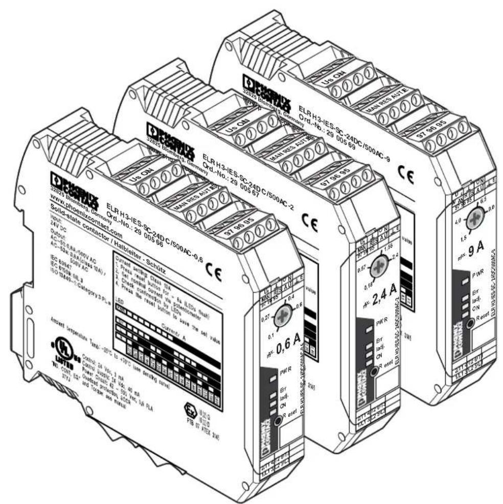
ELR H3-IES-SC-24DC/500AC-2
ELR H3-IES-SC-230AC/500AC-2
ELR H3-IES-SC-24DC/500AC-9
ELR H3-IES-SC-230AC/500AC-9
Art.-Nr.: 2900566
Art.-Nr.: 2900689
Art.-Nr.: 2900567
Art.-Nr.: 2900568
Art.-Nr.: 2900569
Art.-Nr.: 2900570
ENGLISH DEUTSCH
Table of Contents Page
- Short description 13
- Safety Regulations / Installation Notes 14
- Notes on connecting 15
- Function 16
- Application Examples 18
- Technical data 19
- Safety functions 50
- Appendix
8.1. Trigger characteristic curve 52
8.2.Derating curves 53
8.3. Example circuit 54
8.4. Example circuit 55
FRANÇAIS
Sommaire Page
ELR H3-IES-230AC/... ELR H3-IES-24DC/...
Abb.2
4. Funktion
The 3-phase hybrid motor starter ELR H3-IES-SC.../500AC... with overload protection combines three functions into one:
- Right contactor
- Motor overload protection relay
- EMERGENCY STOP contactor up to category 3.
2. Safety regulations / Installation notes
- When working on the device, observe the national safety rules and regulations for the prevention of accidents.
- Disregarding these safety regulations may result in death, serious personal injury or damage to equipment.
- The device may only be started up, assembled, modified or retrofitted by an authorized electrician.
- Before working on the device, disconnect the power.
- In devices with 230 V AC activation, always use the same phase for the control supply voltage and the control inputs!
- For emergency stop applications, the machine must be prevented from restarting automatically by a higher-level control system.
- During operation, parts of electrical switching devices carry hazardous voltages.
- During operation, the protective covers must not be removed from the electric switching device!
- Please retain the instructions.
- The device is an associated item and must not be installed in potentially explosive areas. Adhere to the relevant safety regulations when setting up and operating the relevant equipment.
- The safety regulations applicable when motors are used in the Ex area must be complied with (ATEX directive 94/9/EC).
- If the "Automatic RESET" operating mode is used, the drive is switched on after the cooling time has elapsed provided there is one more activation signal. The cooling time is 20 minutes. An automatic restart is not permissible in the case of applications in the Ex-protection area.
- The device may not be subjected to mechanical and thermal loads that exceed the thresholds specified in the operating manual. If required, the device should be installed in an appropriate housing with suitable protection (e.g. IP54) according to IEC 60529/EN 60529 to provide protection against mechanical and electrical damage. Where dusts are present, the device must be installed in a suitable housing (at least IP64) in acc. with EN 61241.
-
Installation should be carried out following the instructions given in this data sheet. The circuits inside the device must not be accessed during operation.
-
The operating equipment cannot be repaired by the user and must be replaced by an equivalent device. Repairs may only be carried out by the manufacturer.
- The safety data and features provided according to the EC-type examination are listed after the technical data.
- The device carries out a diagnosis of the functions when the drive is being switched on or when it is switched off. In addition, an (electrically) skilled person or a skilled worker who is well acquainted with the relevant standards can conduct the "Motor overload protection" safety function test. For this test, the drive must be activated thus interrupting the current flow in a conductor (e.g. by removing the fuse in the L1 or L3 phase). The hybrid motor starter then switches the drive off within a period of 1.5...2 s. The LEDs for right running activation extinguish and the Err-LED and the reply output are set.
- If the connecting cable for remote reset is longer than 3m in 230 V AC devices (ELR H3-IES-230AC/...), it must be shielded.
- The device must be secured with the help of an access protection during safety-related applications.
- Only use power supply units with safe isolation and PELV in accordance with EN 50178/VDE 0160 (PELV). This prevents short circuits between primary and secondary sides.
Scope of use:
- In circuits in potentially dust-explosive areas of zones 21 and 22, it must be guaranteed that the equipment connected to this circuit complies with categories 2D or 3D or is certified as such.
- This is a product for environment A (industry). In environment B (household), this device can cause undesired wireless problems; in such a case, the user may be obliged to implement appropriate measures.
3. Connection notes
3.1. Mains connection and line protection

CAUTION: Never work when voltage is present! Life-threatening danger!
- When connecting the 3-phase network, it is essential to observe the terminal identification!
- Protection:
| 25 A (Diazed) - Current mains protection in the case of max. cable cross-section 2.5 mm | 2 |
| 16 A FF (6.3 x 32 mm) - Device protection | |
| 16 A (Aut. device B, circuit-breaker) - Short-circuit (1.5 kA network) | |
| 20 A (Motor protecting switch) - Short-circuit (1.5 kA network) | |
| 20 A TRS20R20A (fuse) - Short-circuit (5 kA network) | |
| 25 A gl-gG (fuse) - Short-circuit (10 kA network) | |
- The control supply voltage and control voltage inputs must be operated with power supply modules in acc. with DIN 19240 (max. 5% residual ripple)!

In devices with 230 V AC activation, always use the same phase for the control supply voltage and the control inputs!
- In order to avoid the inductive or capacitive decoupling of disturbing pulses with long control wires, we recommend the use of shielded conductors.

If you want to clamp two conductors under one terminal point, you must use a conductor with the same conductor cross-section.
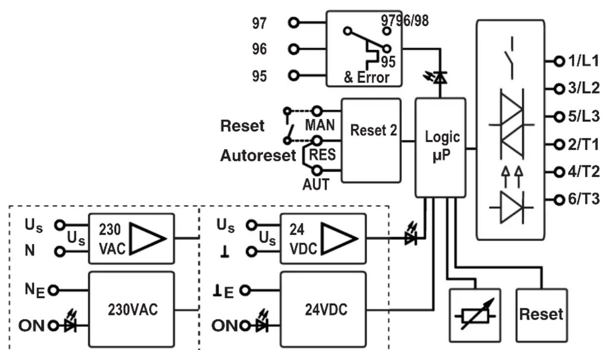
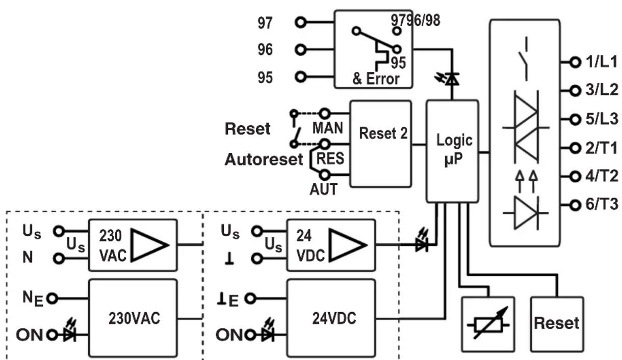
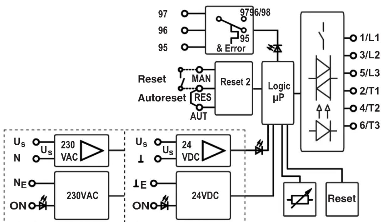
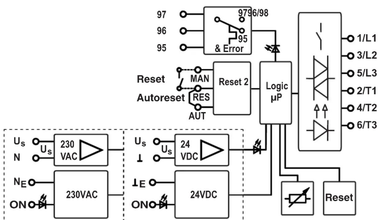
3.2. Block diagram
ELR H3-IES-230AC/... ELR H3-IES-24DC/...
Fig. 2
4. Function
4.1. Visualization - LEDs status
The hybrid motor starter visualizes the operating modes with four LEDs. The functions of the LEDs are oriented towards the NAMUR recommendation NE 44.
The general device status is displayed by a green LED (PWR).
- The activation of the drive is displayed using a yellow LED (ON).
- An internal or external error (process error: overcurrent, asymmetry, phase failure) is indicated by a red LED (ERR).
After the control supply voltage is applied, all LEDs light up once as an LED test.
4.2. Diagnostics function
Thanks to the diagnostics functions, the hybrid motor starter is in a condition to identify several internal errors as well as external errors (errors in the I/O).
- If an error is detected, the device is switched to a safe switch-off mode.
- All internal errors cannot be acknowledged and are saved in the device. The device then cannot be operated.
- In the case of external errors, an error acknowledgment is required to exit the safe switch-off mode.
Explanation:
A = LED switched off / E = LED permanently lit / B = LED flashes approx. 2 Hz (50:50)
| Status | Description | LED: | PWR Green | ERR Red | Iadj Yellow | ON | Error acknowledgement |
| Off No supply voltage (control supply voltage) present | A A | A A - | |||||
| Readiness for operation | Supply voltage (control supply voltage) present | E | A | A | A | A | - |
| Drive switched on E A A E | |||||||
| Internal error | Internal device error - Device replacement required | E | E | A | A | A | Not possible |
| External error in activation or I/O (maintenance requirement, NE44) | Bimetal function: The motor current is greater than the nominal motor current specification (e.g. class 10 A): Cooling time on! (20 minutes) "ON" flashes after 2 minutes: A manual reset is possible. | E | B A E | E | Automatic | 1) | Manual |
| E | B A B | B | Manual | ||||
| Error when restoring the system state: Checksum erroneous. The thermal memory of the bimetal function is set to the max. value. The error must be manually acknowledged in automatic mode. | E | B B B | B | Manual | |||
| Symmetry: The two motor currents deviate from each other by more than 33%. | E | B A A | A | Manual | |||
| Phase failure: Phase failure with pending control signal | B B | A E | Automatic | 2) | |||
| Blocking: The max. measurable motor current is exceeded for more than 2 s. | E | B A B | B | Manual | |||
1) Bridge between the terminals "RES" and "AUT" / 2) No other measures necessary
4.2.1. Error acknowledgment
Three different options are available for error acknowledgement:
Manual (Reset button):
- Actuate the Reset button on the device front side.
If the Reset button is actuated again after approx. 2 s, the hybrid motor starter adopts the error status again.
If the acknowledgment request (pressed reset button) is pending for more than 6 s, the device switches to the "Parameterization" state.
Manual (remote acknowledgement operating point):
- Connect a button (N/O contact) between the MAN and RES terminals.
An acknowledgement is triggered if a positive edge is identified at the MAN input. If a negative edge is not identified after approx. 2 s, the hybrid motor starter adopts the error status again, since the possibility of a manipulation or a defect in the acknowledgement circuit cannot be ruled out.
Automatic:
- Establish an electrical connection between the RES and AUTO terminals.
After the activation of the bimetal monitoring and a subsequent cooling, the device carries out an automatic acknowledgement.

The RES terminal provides the voltage for a reset.
In variants with the rated control supply voltage of 24 V DC, this is 24 V DC and in the case of 230 V AC, it is a special system voltage.
4.2.2. Feedback
If the hybrid motor starter detects an error, the feedback relay is activated, i.e. the N/O contact is closed or the N/C contact is opened. This behavior corresponds to that of a motor protecting switch or a motor overload protection relay.

The feedback is used for signaling and is not a part of the safety chain. It is thus not included in the safety monitoring.
4.3. Parameterization - Nominal current setting
- Actuate the Reset button for more than 6 s in order to switch to the "Parameterization" operating mode; the green LED PWR flashes again.
In the Parameterization mode, the LEDs are switched off after every 2 s for 0.3 s in order to different this mode from other operating modes. - Set the nominal current of the drive using the 240^ potentiometer. The nominal current is specified in 16 stages. The four LEDs display the set current.
- Save the value by actuating the Reset button again (non-volatile range of the data memory).
- Actuate the Reset button for more than 2 s (and less than 6 s) to display the set current for 3 s. This function is possible only if 1) the device is not activated, and 2) there is no defect in the device.

From a motor current of 45 A, the blocking monitoring is activated (see 8.1. Trigger characteristic).
| Code Nominal current [mA] | ||||||
| PWR | ERR | adj. | ON | 0.6 A 2 A | 9 A | |
| 0 | 0 | 0 | 0 | 7 | 5 | |
| 0 | 0 | 0 | 1 | 110 | 250 | 2000 |
| 0 | 0 | 1 | 0 | 145 | 410 | 2500 |
| 0 | 0 | 1 | 1 | 180 | 560 | 3000 |
| 0 | 1 | 0 | 0 | 215 | 710 | 3500 |
| 0 | 1 | 0 | 1 | 250 | 870 | 4000 |
| 0 | 1 | 1 | 0 | 285 | 1020 | 4500 |
| 0 | 1 | 1 | 1 | 320 | 1170 | 5000 |
| 1 | 0 | 0 | 0 | 355 | 1330 | 5500 |
| 1 | 0 | 0 | 1 | 390 | 1480 | 6000 |
| 1 | 0 | 1 | 0 | 425 | 1630 | 6500 |
| 1 | 0 | 1 | 1 | 460 | 1790 | 7000 |
| 1 | 1 | 0 | 0 | 495 | 1940 | 7500 |
| 1 | 1 | 0 | 1 | 530 | 2090 | 8000 |
| 1 | 1 | 1 | 0 | 565 | 2250 | 8500 |
| 1 | 1 | 1 | 1 | 600 | 2400 | 9000 |
5. Application examples
5.1. EMERGENCY STOP
Integrating a hybrid motor starter into an EMERGENCY STOP chain is pictured in Fig. 3 (page 54).
Here, the control voltage supply is switched off via the safety relays, as soon as the EMERGENCY STOP button is actuated.

Switching off the control voltage supply with a controlled motor always results in wear in the hybrid motor starter.
This switch should only be used if no more than 10,000 shutdowns can be expected over the entire lifespan system.
If the switch-off is performed, for instance, from a "safe controller" with semiconductor outputs, the residual voltage must be < 5V DC. Interruptions ≤ 1 ms are filtered.
5.2. Safety door (EMERGENCY STOP)
In applications where the safety switch-off is a normal operating mode, such as in the case of safety door or two-hand applications, a circuit as per Fig.4 (page 55) should be used.
In this application, the control current circuit is switched and not the control supply voltage.
If the switch-off is performed, for instance, from a "safe controller" with semiconductor outputs, the residual voltage must be < 5V DC. Interruptions ≤ 3 ms are filtered.
5.3. Motor overload protection
All safety-relevant functions are realized by the hybrid motor starter without any external influence. Special circuit technologies are not necessary.
The wiring of the load current circuit should be realized in the above examples. The connection of the module current supply can, however, be established directly to the voltage source without the PSR safety relay. The same is applicable for the activation.
5.4. Motor with brake
If a motor with a brake (connection in the motor terminal block) is connected, the 400 V AC brake must be connected to the 2/T1 and 6/T3 connections. A 230 V AC brake should be connected to the 4/T2 connection and the star point of the motor.

Please note: Motor current monitoring must be increased by the value of the brake (nominal current brake). Set this as per the hybrid motor starter (see Item 4.3, page 17)!
5.5. Auxiliary relay connection
Auxiliary relay (e.g. PLC RSC 230UC/21, Order No.: 2966207) for activating the external brakes or feedback to the PLC must be connected to the connection "4T2" and "N" of the system.
- Technical data
| Type | Order No. | ELR H3-IES-SC-24DC/500AC-0,6 2900566 |
| ELR H3-IES-SC-24DC/500AC-2 2900567 | ||
| ELR H3-IES-SC-24DC/500AC-9 2900569 | ||
| ELR H3-IES-SC-230AC/500AC-0,6 2900689 | ||
| ELR H3-IES-SC-230AC/500AC-2 2900568 | ||
| ELR H3-IES-SC-230AC/500AC-9 2900570 | ||
| Input data ELR...-24DC/... ELR...-230AC/... | ||
| Rated control supply voltage Usas per IEC 60947-1/UL 508 | 24 V DC 230 V AC (50/60 Hz) | |
| Control supply voltage range 19.2 ... 30 V DC | 85 ... 253 V AC(32 V DC, max. 1 min.) | |
| Control supply voltage Switching level "Safe off" < 5 V | DC < 5 V AC | |
| Rated control supply current as per IEC 60947-1 | ≤ 40 mA ≤ 4 mA | |
| Control input ON:Switching level "Low" -3 ... 9.6 V DC < 44 V ACSwitching level "Safe off" < 5 V DC < 5 V ACSwitching level "High" 19.2 ... 30 V DC 85 ... 253 V ACInput current ≤ 5 mA ≤ 7 mA | ||
| Output data | load side | ELR...-0.6 ELR...-2 ELR...-9 |
| Circuit principle | Safety end level with bypass, three-phaseelectrically isolated switch-off | |
| Rated operating voltage Ueas per IEC 60947-1 | 500 V AC (50/60 Hz) | |
| Operating voltage range as per IEC 60947-1 | 42...550 V AC42...500 V AC | |
| Load current at 20°C (see 8.2. Derating curve) | 0.075...0.6 A 0.18...2.4 A 1.2...9.0 A | |
| Load current at 20°C without safety function and asymmetry recognition (see 8.2. Derating curve) | 0...0.6 A 0...2.4 A 0...9.0 A | |
| Rated operating current Ieas per IEC 60947-1 | ||
| AC-51as per IEC 60947-4-3 | 0.6 A 2.4 A 9 A | |
| AC-53aas per IEC 60947-4-2 | 0.6 A 2.4 A 6.5 A | |
| as per UL 508 | 0.6 A 2.4 A 6.5 A | |
| Nominal switching performanceas per UL 508 | ||
| Full Load (power factor = 0.4) | 0.3 kW (0.4 HP) 0.9 kW (1.2 HP) 2.3 kW (3.0 HP) | |
| Full Load (power factor = 0.8) | 0.5 kW (0.6 HP) 1.7 kW (2.2 HP) 4.6 kW (6.1 HP) | |
| Leakage current (input, output) | 0 mA 0 mA 0 mA | |
| Residual voltage at Ie | < 300 mV < 300 mV < 500 mV | |
| Surge current | 100 A (t = 10 ms) | |
| Input protective circuit | Varistors | |
| Short circuit current rating SCCR acc. to UL 508 - suitable for use on a circuit capable of deliv- ring not more than 5 kA rms symmetrical amperes, 500 V maximum-suitable for use on a circuit capable of delive- ring not more than 100 kA rms symmetrical am- peres, 500 V maximum when protected by a 30 A class J or CC fuse | ||
6. Technical data
| Reply output | |||
| Contact type Single contact, 1 PDT | |||
| Contact material Ag alloy, hard gold-plated | |||
| when used as Signal contact Power contact | |||
| Max. switching voltage 30 V AC / 36 V DC 250 AC/DC | |||
| Min. switching voltage 100 mV 12 V AC/DC | |||
| Max. continuous load current Io | 50 mA 6 A | ||
| Min. switching current 1 mA 10 mA | |||
| Max. interrupting rating, Ohmic load 24 V DC | 1.2 W | 140 W | |
| 48 V DC | - | 20 W | |
| 60 V DC | - | 18 W | |
| 110 V DC | - | 23 W | |
| 220 V DC | - | 40 W | |
| 250 V AC | - | 1500 VA | |
| Measurement techn. (in ref. to the trigger characteristic, 8.1.) | ELR...-0.6 ELR...-2 ELR...-9 | ||
| Current measurement | |||
| Area | 0.075...0.6 A | 0.18...2.4 A | |
| Symmetry monitoring | |||
| Amount lmax> lnom => (lmax - lmin / lmax) | ≥ 33 % / ≥ 67 % | ≥ 33 % / ≥ 67 % | |
| Amount lmax< lnom => (lmax - lmin / lnom) | ≥ 33 % / ≥ 67 % | ≥ 33 % / ≥ 67 % | |
| Response time | 2 min. / 1.8 s | 2 min. / 1.8 s | |
| Blocking protection | |||
| I(L1) or I(L3) | - | - | |
| Response time | - | 2 s | |
| Trigger characteristic (see diagram 8.1.) as per IEC 60947 | - | Class 10A | |
| Cooling time | - | 20 min. | |
| Operating elements | |||
| Operating voltage display | LED PWR (green) | ||
| Device and process error display | LED ERR (red) | ||
| Activation display Forward running | LED ON (yellow) | ||
| Button | Error acknowledgment | ||
| Potentiometer for nominal motor current setting | 240° | ||
| General data | ELR...-0.6 ELR...-2 ELR...-9 | ||
| Power dissipation min./max. | 0.88 W/2.5 W | 0.88 W/4.1 W | |
| Max. switching frequency (pulse/pause times 50:50) | 2 Hz | ||
| Ambient temperature range Operation | -25°C to +70°C | ||
| Transport, storage | -40°C to +80°C | ||
| Service life | 3 x 10^7 cycles | ||
| Degree of protection | IP20 | ||
6. Technical data
| Rated surge current between control input, control supply and switching voltage ·Network nominal voltage (≤500 V AC) ·Network nominal voltage (≤300 V AC, For example, 230/400 V AC, 277/480 V AC) ·Network nominal voltage (300...500 V AC) Control input, control supply voltage and reply output Reply output and switching voltage ·Network nominal voltage (≤500 V AC) ·Network nominal voltage (≤300 V AC, For example, 230/400 V AC, 277/480 V AC) ·Network nominal voltage (300...500 V AC) | 6 kV (ELR H3-IES-24DC/...) Safe isolation (EN 50178) Safe isolation (IEC 60947-1) Basic isolation (IEC 60947-1) Safe isolation (IEC 60947-1) Safe isolation (EN 50178) Safe isolation (IEC 60947-1) Basic isolation (IEC 60947-1) |
| Rated surge current between control input, control supply and switching voltage ·Network nominal voltage (≤500 V AC) Control input, control supply voltage and reply output Reply output and switching voltage ·Network nominal voltage (≤300 V AC, For example, 230/400 V AC, 277/480 V AC) ·Network nominal voltage (300...500 V AC) | 4 kV (ELR H3-IES-230AC/...) Basic isolation (IEC 60947-1) Safe isolation (IEC 60947-1) Safe isolation (IEC 60947-1, EN 50178) Basic isolation (IEC 60947-1) |
| Surge voltage category III | |
| Pollution degree 2 | |
| Standards/specifications | IEC 60947-4-2 / IEC 61508-1 / EN 954-1 / ISO 13849-1 |
| Power station requirement | DWR 1300 / ZXX01/DD/7080.8d |
| Coordination type 1 | |
| Mounting position vertical (horizontal DIN rail) | |
| Mounting (refer to 8.2. Derating curves) | Can be aligned with ≥20 mm spacing |
| Housing: Material | PA 66 (22.5/99/114.5) mm |
| Dimensions (W/H/D) | |
| Connection data (conductor cross-section) Screw terminal blocks (solid/stranded) M3 thread, recommended torque | See connection notes (page 15)! 0.14-2.5 mm² (AWG 26-14) 0.5-0.6 Nm / 5-7 lbs-ins |
| Weight Approx. 212 g | |
| Conformance / Approvals | |
| acc. to UL 508 | NLDX File: E228652 NMFT File: E323771 |
| EU examination certificate as per ATEX | II (2) G, II (2) D PTB 07 ATEX 3145 and "7.2 Motor overload protection" |
| Safety level See "7.1 Safe shutdown" |
ELR H3-IES-230AC/... ELR H3-IES-24DC/...
Fig. 2
4. Fonction
5.1. ARRET D'URGENCE
ELR H3-IES-230AC/... ELR H3-IES-24DC/...
Fig.2
4. Función
4.1.Bn3yaIIN3aIyra - CBeToIONoIbI COCTOHHN
IocpeDCTBOM YeTbipex CBeToNDIOOB KOMHnHPOBaHHb IyckaTeIb 3JIeKTPoDBnraTeIa OTO6paKaet pa6oue coCtOHa. FyHKsIN CBeToNDIOOB COOTBeTCTByIOT peKomeHdaZmNAMUR NE 44.
-Посрдьом зеленогCBeToNDoDA(PWR)ОTOбражаetс obuee coCTOЯне yCTpoiCTBA.
-Управлины пиворим отообрахаетс посядтбом щел Toro сбetoюда (ON).
BHyTpeHHra nn BHeHnra Oun6ka (Oun6ka npoucecca: CBepxTOK, acmmMeTpnuHocTB, 06pbIB pa3bl) oTo6paKaetc nocpeDCTBOM KpacHO rCBeToNDoA (ERR).
IocJe npiloxeHnHaipxKeHnPiTaHnYcENyypaBHeHnOndokpaTHo 3aropaOTcBCE CBETODIObI B KaueCTBe IPOBepKn CBEToNDIOB.
4.2.FyHKnIaNarHOctnK
Blaoradpa3nHbIM yHKmM dnaHocTKK KOM6HHPOBaHHbI NyCaTeIb 3JeKToBnTaTeJI MOKeT pacno3HaBaTb MHOrne BHTpeHHne, a TaKHe N BHeuHHe OwN6Kn (OwN6Kn nepnepnHbIX yCTpoiCTB).
- PnO6HApUKeHHN OUn6Kn YcTPOIcTBo HaxOHTcB B 6e3OnaCHOM OTHJIoueHHOM COCTOHHN.
Bce BHyTpHnne Oun6Kn CoXpaHnTcB namrtn yCTpOncTa, a He KBNtpyoTc. NOBTOhBBOy cTPONCBa B 3KcnIyatauHO HEO3MOxHe.
-При Налочи BHeшней OшнбкДЯ BBIXOДИЗ 6e3OnaCHOrO OTKHQUeHHORO COCTOHRN Tpe6yeTcK BINTnPOBaHne OSh6KN.
0603haeHHa:
A = CBeToIIOB BbIKIIOUeH / E = CBeToIIOB IopNT HeIpepbIBHO / B = CBeToIIOB MIRaET npI6I. 2 Γι (50:50)
More safety-related data is available on request.
Trigger characteristic curve at 20^ [1]
"EMERGENCY STOP (two channels)" - (acc. to Cat. 3, SIL 3, PL e):
ELR H3-IES-SC-.500AC-. with a higher-level safety relay combination.
To reach the maximum service life, please apply the example from page 55, if possible!
Further applications / example circuits are available on request.
"Safety door / two-hand / EMERGENCY STOP application (two channels)" -
(acc. to Cat. 3, SIL 3, PL e): ELR H3-IES-SC-/500AC-/ with a higher-level safety relay combination
Further applications / example circuits are available on request.
D-32823 Blomberg, Germany
Fax +49-(0)5235-341200 Phone +49-(0)5235-300
www.phoenixcontact.com
- ENGLISH DEUTSCH
- Table of Contents Page
- FRANÇAIS
- Sommaire Page
- Funktion
- Safety regulations / Installation notes
- Scope of use:
- Connection notes
- Mains connection and line protection
- CAUTION: Never work when voltage is present! Life-threatening danger!
- Block diagram
- Function
- Visualization - LEDs status
- Diagnostics function
- Explanation:
- Error acknowledgment
- Manual (Reset button):
- Automatic:
- Feedback
- Parameterization - Nominal current setting
- Application examples
- EMERGENCY STOP
- Switching off the control voltage supply with a controlled motor always results in wear in the hybrid motor starter.
- Safety door (EMERGENCY STOP)
- Motor overload protection
- Motor with brake
- Auxiliary relay connection
- Technical data
- Fonction
- ARRET D'URGENCE
- Función
- 4.1.Bn3yaIIN3aIyra - CBeToIONoIbI COCTOHHN
- 4.2.FyHKnIaNarHOctnK
Brand : Phoenix Contact
Model : ELR H3-IES-SC-230AC/500AC-2
Category : Starter motor