TD-007-02 - Jack Vevor - Free user manual and instructions
Find the device manual for free TD-007-02 Vevor in PDF.

| Product Type | Motorcycle Stand (Jack) |
| Brand | Vevor |
| Model | TD-007-02 |
| Maximum Load Capacity | 1100 lb (499 kg) |
| Stand Height | 15.2 inches (38.6 cm) |
| Main Material | Steel |
| Intended Use | Off-Road Motorcycle (Dirt Bike) |
| Assembly Required | Yes |
| Number of Support Points | 2 (support arms) |
| Tools Needed for Assembly | Wrenches, screwdriver |
| Safety Instructions Included | Yes (read manual) |
| Inspection Before Use | Check stability and screw tightness |
| Recommended Storage Environment | Dry and well-ventilated place |
| Warranty | Electronic Warranty Certificate |
| Technical Support | www.vevor.com/support |
| Included Parts | Main frame, support arms, screws |
| Recommended Maintenance | Regular inspection monthly or quarterly |
| Recommended Cleaning | Dry cloth |
| Important Safety Precautions | Do not overload, wear gloves and safety glasses |
| Spare Parts / Repairability | Contact Vevor support |
Frequently Asked Questions - TD-007-02 Vevor
User questions about TD-007-02 Vevor
0 question about this device. Answer the ones you know or ask your own.
Ask a new question about this device
Download the instructions for your Jack in PDF format for free! Find your manual TD-007-02 - Vevor and take your electronic device back in hand. On this page are published all the documents necessary for the use of your device. TD-007-02 by Vevor.
USER MANUAL TD-007-02 Vevor
Technical Support and E-Warranty Certificate www.vevor.com/support
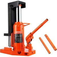
DIRT BIKE STAND
MODEL: TD-007-02
We continue to be committed to provide you tools with competitive price. "Save Half", "Half Price" or any other similar expressions used by us only represents an estimate of savings you might benefit from buying certain tools with us compared to the major top brands and does not necessarily mean to co all categories of tools offered by us. You are kindly reminded to verify carefully when you are placing an order with us if you are actually Saving Half in comparison with the top major brands.
VEVOR®
DIRT BIKE STAND
Model: TD-007-02
natural_image
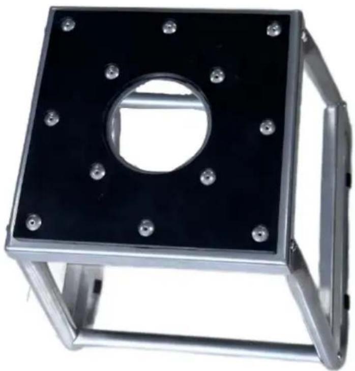
Metallic square frame with central hole and eight mounting holes (no text or symbols visible)NEED HELP? CONTACT US!
Have product questions? Need technical support? Please feel free to contact us:
Technical Support and E-Warranty Certificate www.vevor.com/support
This is the original instruction, please read all manual instructions carefully before operating. VEVOR reserves a clear interpretation of o user manual. The appearance of the product shall be subject to the product you received. Please forgive us that we won't inform you ag there are any technology or software updates on our product.
SAFETY PRECAUTIONS

Warning - To reduce the risk of injury, user must read in manual carefully.
- Read and understand this entire manual before assembling, installing, operating, or servicing this product. Failure to follow these warnings and instructions can cause death, personal injury or damage to valuable proper
- Adhere to all Department of Transportation (D.O.T.) requirements when using this product.
- Use common sense when working. Stay alert and concentrate when setting up and using this product. Never work while under the influence of alcohol drugs or medications.
- While assembling and using this product keep work area clean and well lighted. Keep spectators and children out of the work area.
- Dress appropriately. Never wear loose fitting clothing or jewelry when working. Contain long hair, and keep hair, clothing and gloves away from moving
● Always keep this stand away from children. - Check the stand is in good condition before using it.
SPECIFICATIONS
| Model Series | TD-007-02 |
| Maximum Load Capacity (lbs) | 1100 |
| Support height (inch) | 15.2 |
PRODUCT PARAMETERS
natural_image
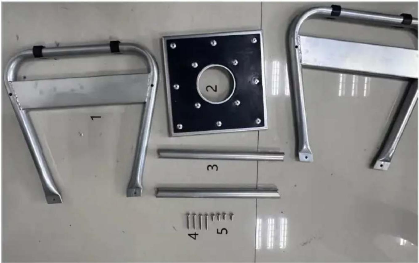
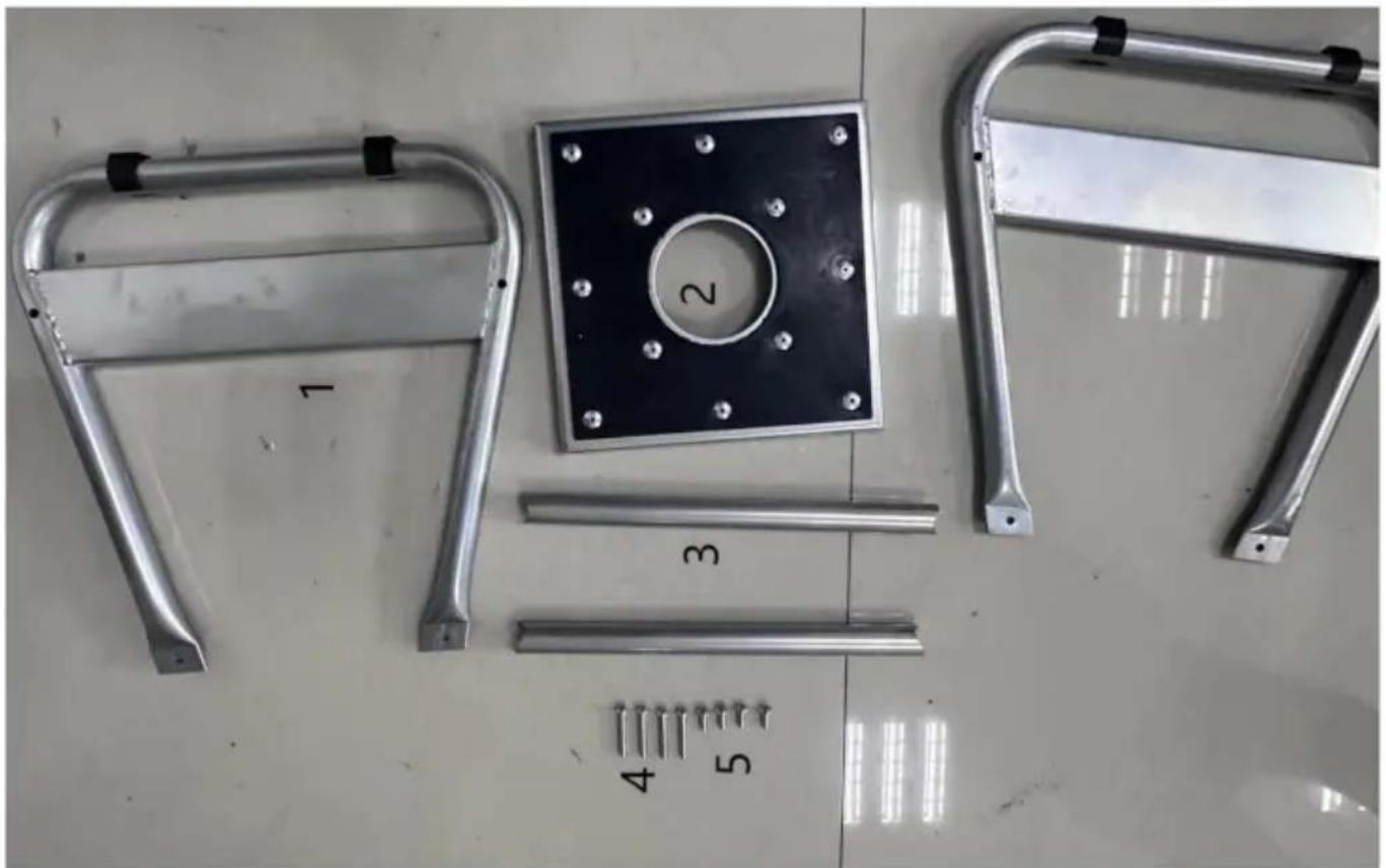
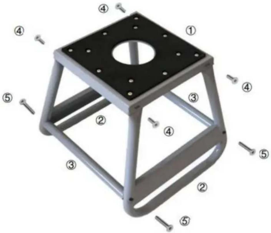
Metal frame components laid out on a tiled floor, including metal brackets and a square plate with bolt holes (no text or symbols visible)| SN | Description | Qty |
| 1 | Bracket main body. | 2 |
| 2 | Platform. | 1 |
| 3 | Support tube | 2 |
| 4 | Screw M6×40 (mm) | 4 |
| 5 | Screw M6×15 (mm) | 4 |
INSTALLATION INSTRUCTIONS
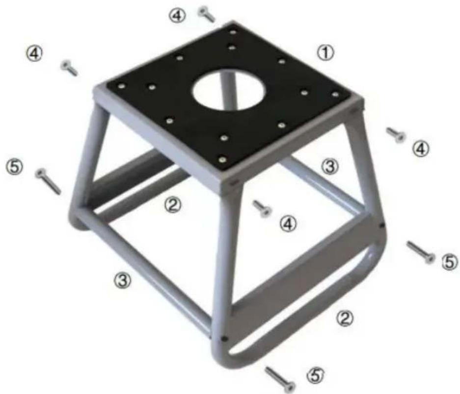
- Preparatory Work and Component Inspection
- Prepare the necessary tools such as wrenches and screwdrivers for installation, and carry out the operation on a flat and solid surface. Open the package and check whether all components of the motorcycle support stand, including the main body structure, support arms, screws, etc., are complete and undamaged.
- Assembly of the Main Body
- Place the main body structure properly and start installing the screws. Note that during the initial stage of installation, do not tighten the screws too tight facilitate subsequent adjustments.
- Installation of the Support Arms
- Take out the support arms and connect them to the main body structure. time, do not tighten the screws either. After connection, check whether the movable joints of the support arms can rotate flexibly.
- Leveling and Tightening of Screws
- After all the screws are installed in place, check whether the entire support stand is level. If it is not level, make fine adjustments to the to make the support stand reach a horizontal state. After confirming this level, evenly tighten all the screws to ensure that all components firmly connected.
5. Stability Test
- After the installation is completed, gently shake the support stand to check stability. If any instability is found, it is necessary to check the connection of components and the tightness of screws and make adjustments accordingly.
Precautions
1. Weight Limit
- The maximum load-bearing capacity of this support stand is 1100 lbs. Overloading is strictly prohibited to prevent damage to the support stand and motorcycle from toppling over, which may cause danger.
2. Regular Inspection
- Before each use, simply check whether the components of the support start are loose and whether the support arms are in normal condition. Conduct a comprehensive inspection regularly (such as monthly or quarterly) to ensure its normal operation.
3. Operation Specifications
- When placing the motorcycle on the support stand, the operation should be smooth and slow to avoid slipping. When carrying out maintenance, use fixing devices such as ropes to fix the motorcycle (support stand.
5. Storage Environment
- When the support stand is not in use, store it in a dry and well place to prevent rusting and corrosion of metal components and exter service life.
7. Safety Protection
- When using the support stand for maintenance operations, it is recommended to wear safety protection equipment such as gloves and goggles. If abnormal sounds, component deformation or other situations are found in the support stand, stop using it immediately and seek professional assistance.
VEVOR®
TOUGH TOOLS, HALF PRICE
Technical Support and E-Warranty Certificate
www.vevor.com/support
VEVOR®
TOUGH TOOLS, HALF PRICE
natural_image
Metallic square frame with central hole and eight mounting holes (no text or symbols visible)BESOIN D'AIDE? CONTACTEZ-NOUS!
PARAMÈTRES DU PRODUIT
natural_image
Overhead view of a metal frame assembly with numbered components (no text or symbols visible)| SN | Description | Quantité |
| 1 | Corps principal du support. | 2 |
| 2 | Plate-forme. | 1 |
| 3 | Tube de support | 2 |
| 4 | Vis M6×40 (mm) | 4 |
| 5 | Vis M6×15 (mm) | 4 |
INSTRUCTIONS D'INSTALLATION
natural_image
Metallic square frame with central hole and eight mounting holes (no text or symbols visible)natural_image
Overhead view of a metal frame assembly with numbered components (no text or symbols visible)www.vevor.com/support
VEVOR®
TOUGH TOOLS, HALF PRICE
natural_image
Metallic square frame with central hole and eight mounting holes (no text or symbols visible)natural_image
Metal frame components laid out on a white surface, including metal brackets and a square plate with bolt holes (no text or symbols visible)natural_image
Metallic square frame with central hole and eight mounting holes (no text or symbols visible)natural_image
Overhead view of a metal frame assembly with numbered components (no text or symbols visible)natural_image
Metallic square frame with central hole and eight mounting holes (no text or symbols visible)POTRZEBUJESZ POMOCY? SKONTAKTUJ SIĘ Z NAMI!
natural_image
Overhead view of industrial metal frame components including a square plate with bolt holes and four numbered parts (1–5) arranged on a tiled floor.natural_image
Metallic square frame with central hole and eight mounting holes (no text or symbols visible)HULP NODIG? NEEM CONTACT MET ONS OP!
natural_image
Overhead view of a metal frame assembly with numbered components (no text or symbols visible)garantiecertificaat www.vevor.com/support
VEVOR®
TOUGH TOOLS, HALF PRICE
natural_image
Metallic square frame with central hole and eight mounting holes (no text or symbols visible)BEHÖVER HJÄLP? KONTAKTA OSS!
natural_image
Metal frame components laid out on a tiled floor, including metal brackets and a square plate with bolt holes (no text or symbols visible)www.vevor.com/support