IOG-1 - Air Conditioning Vevor - Free user manual and instructions
Find the device manual for free IOG-1 Vevor in PDF.

| Product Type | Portable Air Conditioner |
| Brand | Vevor |
| Model | IOG-1 |
| Cooling Capacity | 4000 BTU |
| Rated Power | 400 W |
| Refrigerant | R290 / 80 g (slightly flammable, environmentally friendly) |
| Voltage/Frequency (110V) | AC 110V ~ 60 Hz |
| Voltage/Frequency (220V) | AC 220V ~ 50/60 Hz |
| Temperature Range | 16 °C to 30 °C |
| Noise Level | <55 dB(A) |
| Dimensions (L x W x H) | 540 x 300 x 350 mm |
| Net Weight (110V) | 17 kg |
| Net Weight (220V) | 15.7 kg |
| Operating Modes | Cooling, sleep, dehumidification, ventilation |
| Wind Speed | Low, High (adjustable) |
| Timer | Delayed off and delayed start |
| Remote Control | Yes, included |
| Ambient Light | Yes, switchable |
| Safety Functions | Anti-freeze protection, 3 min compressor protection, anti-overflow protection, fault protection, power-off memory |
| Drainage | Manual or continuous (depending on setting) |
| Filter Maintenance | Monthly wash with warm water and neutral detergent |
| Included Parts | Main unit, exhaust hose (x2), drain hose, conduit seals, screws, screwdriver, remote control |
| Warranty | Electronic warranty via www.vevor.com/support |
Frequently Asked Questions - IOG-1 Vevor
User questions about IOG-1 Vevor
0 question about this device. Answer the ones you know or ask your own.
Ask a new question about this device
Download the instructions for your Air Conditioning in PDF format for free! Find your manual IOG-1 - Vevor and take your electronic device back in hand. On this page are published all the documents necessary for the use of your device. IOG-1 by Vevor.
USER MANUAL IOG-1 Vevor
Technical Support and E-Warranty Certificate www.vevor.com/support
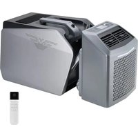
PORTABLE AIR CONDITIONER
MODEL:IOG-1
We continue to be committed to provide you tools with competitive price. "Save Half", "Half Price" or any other similar expressions used by us only represents an estimate of savings you might benefit from buying certain tools with us compared to the major top brands and does not necessarily mean to co all categories of tools offered by us. You are kindly reminded to verify carefully when you are placing an order with us if you are actually Saving Half in comparison with the top major brands.
MODEL:IOG-1
natural_image
Line drawing of a portable air conditioner unit (no text or symbols)NEED HELP? CONTACT US!
Have product questions? Need technical support? Please feel free to contact us:
Technical Support and E-Warranty Certificate www.vevor.com/support
This is the original instruction, please read all manual instructions carefully before operating. VEVOR reserves a clear interpretation of o user manual. The appearance of the product shall be subject to the product you received. Please forgive us that we won't inform you ag there are any technology or software updates on our product.
Thank you for purchasing this portable air conditioner. Please read the entire manual carefully before use. This manual serves as a general g for operation of your portable air conditioner. Please note that some may differ slightly from your specific model. However, the basic function and safety guidelines outlined here will apply to your unit. While your machine may vary in certain aspects such as available modes or cor panel layout, the fundamental operation and use should be consistent what is described. Please take a few minutes to read through the man fully and familiarize yourself with the features of your portable air conditioner before use. Refer closely to your unit itself to identify any variations from what is shown. Enjoy your new portable air conditione
- Do not use a broken or unsuitable outlet.
- Do not use the machine in the following situations.
A: Close to the source of the fire B: Sites at risk of oil splashing
C: Avoid direct sunlight exposure D: Sites at risk of water splashir
E: Close to bathroom, shower room, pool.
- Do not put fingers, or other slender objects, etc. into the air outlet, sure to tell children about these dangers.
- In order to make the compressor place correctly, the machine should be placed in the direction indicated by the carton during transportation.
- When cleaning the machine, be sure to cut off the power in advar
- Turn off the computer and disconnect the power supply before movi slowly when moving. 7. Do not cover the machine, otherwise there is of fire.
- Air conditioner installation should comply with national wiring codes at all power supplies should comply with British electrical safety standards.
- Unplug the power plug when thunder rumbles.
- Do not directly turn off the air conditioner with the power switch.
- In case of abnormal phenomena such as burning smell, operation be stopped and power cut off.
- Children should be used under adult supervision and should not be used as toys.
- This product is not suitable for the following groups: children, disability people, mentally ill people, people with intellectual disabilities. Unless it is under the supervision of a normal person.
R290 refrigerant warning language
- Please read this manual before installation, use and maintenance.
- Do not use any method to accelerate the defrosting process or clear frosting part except as specifically recommended by the manufacturer.
-
Do not puncture or ignite the air conditioner.
-
The air conditioner shall be stored in rooms without continuous fire sources (e.g. gas appliances ignited by open flame, electric heaters, 5. In case of maintenance, please contact the nearest after-sales service center. Strictly follow the operation manual provided by the manufacturer and prohibit maintenance by non-professionals.
-
Should comply with the relevant national gas laws and regulations.
-
Remove the refrigerant from the cleaning system for maintenance or scrapping.
The air conditioner uses an environmentally friendly R290 refrigerant. It is a slightly combustible refrigerant, although it can burn and explode certain conditions, but as long as you follow the table below, install i room with the right area, and use it correctly, there is no risk of co and explosion.
Compared with ordinary refrigerant, R290 is an environmentally-friendly refrigerant that does not destroy the ozone layer, and its greenhouse value is also very low.
PART LIST
| NO. | PICTURE | NAME | QTY |
| 1 | 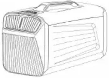 | Air conditioning host | 1 |
| 2 |  | operating instruction | 1 |
| 3 | 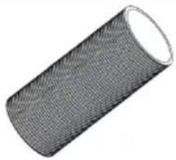 | The exhaust pipe | 2 |
| 4 | 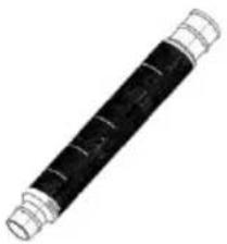 | drain pipe (inner diameter:12mm) | 1 |
| 5 | 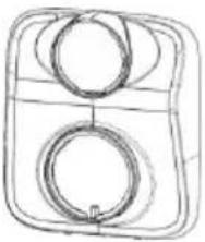 | the front air pipe join | 1 |
| 6 | 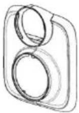 | the front air pipe join | 1 |
| 7 | 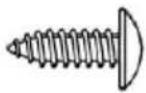 | Screw | 1 |
| 8 | 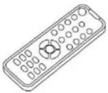 | Remote | 1 |
| 9 |  | Screwdriver | 1 |

PARAMETER LIST
| Product name | Portable air conditioner | |
| Product model | IOG-1 | IOG-1 |
| Rated voltage/frequency | AC110V~60Hz | AC220V~50/60Hz |
| Cooling capacity | 4000BTU | |
| Rated power | 400W | |
| Refrigerants | R290/80g | |
| Temperature Range | 16-30°C | |
| Noise | <55dB(A) | |
| Body dimensions | 540x300x350mm | |
| Unit net weight | 17kg | 15.7kg |
SECURITY & WARNINGS
!WARNING MATTERS
Use the appliance as described in the Instructions for Use Guide.
- Like other electrical appliances, this instruction manual aims to include the warning of events as much as possible and the usual practices need to use in the operation and installation of the electrical appliance
- Children or people without self-care ability are prohibited to use this product when unsupervised.
- The electrical appliance is designed for household indoor use, and can be used for other purposes.
- If the power cord is damaged, it must be replaced by the manufacturer, service agent or equivalent organization to avoid danger.
- Any change or replacement of the appliance characteristics is very dangerous.
- If the appliance needs to be repaired, please contact the technical center authorized by the manufacturer, adhere to the use of the original vulnerable parts, repair by unauthorized individuals are dangerous, and the warranty is invalid.
- The electrical appliance must be installed with grounding, and the int circuit must be tested by the technical personnel with electrical qualific
- Do not use the electrical appliance outdoors.
- Do not plug the air outlet and air inlet.
- No epitaxial cable lines shall be used.
- Pull out the power plug before cleaning or maintaining the appliance not pull the cable to move the appliance.
- Please do not install the electrical appliance in a room with natural gas, gasoline and sulfur, and it can not be installed close to the heat source.
- Do not use the electrical appliance on the slope ground.
- Be sure to maintain a distance of at least 45cm from flammable materials(such as alcohol)or durable containers(e.g.aerosol tanks).
- Do not place heavy objects or hot objects on the top of the machine Clean the filter screen regularly.
- In the process of transporting the electrical appliance, please keep it vertical and place it on one side. When moving the electrical appliance, please empty the water in the water tank first. After the transportation, if you need to start it, please wait for half an hour.
- R290 It is a refrigerant that complies with the relevant environmental standards. The cycle of the refrigerant in the electrical appliances is closed. After the end of the service life, please submit the electrical appliances to a special recycling center.
- Packages are recyclable, so it is recommended to place them in the corresponding waste sorting recycling bins.
- The installation of the electrical appliance must be consistent with relevant national laws and regulations.
POWER
If you move the appliance, please restart it after half an hour. Before inserting the wire plug into the power outlet, check:
- The main power supply system meets the power supply requirement marked on the nameplate of the electrical appliance.
- Power sockets and circuits are suitable for this appliance.
- To match the power socket and the plug, please replace a matching power plug with a qualified electrician.
- Power socket must have a grounding setting.
- Electrical cables must be replaced by the approved service personnel. The manufacturer is not liable for not to with the safety rule
- If the appliance has Wi-Fi function, its transmission power is less than dBm. The RF range is: 2412 MHz-2472 MHz.
PRODUCT OVERVIEW
- The working mode of this product includes: refrigeration mode, sleep mode, dehumidification mode, air supply mode.
- This product consists of main board, remote control, display panel, sensor, compressor, internal and external motor, etc.
- This product has anti-freezing protection and compressor 3 minute protection, fault protection, power loss memory and other functions.
- The product is manufactured by default.
Compressor protection
The minimum time to start again after the compressor stops is 3 minutes. You do not need to wait for 3 minutes for the first power or the power off, you do not need to wait for the power on again for 3 minutes, and you need to wait for 3 minutes after the power on on a The compressor shall run for at least 3 minutes after opening, even if shutdown conditions are met, it does not run for 3 minutes, except for shutdown.
Power-off memory
Standby before power failure, or set the timing shutdown function, powered again and enter standby.
Before the power is off, the original mode, set temperature, wind speed, temperature unit, water motor enabling switch, etc.
Anti-overflow function
When the water level of the air conditioner is full, the ash icon of the will flash the E4 fault sign of the E 4. The compressor stops working water level returns to normal.
Fault protection
Air conditioning is abnormal, the sensor is open or broken, stop working, please hand over to the professional after-sales service center
OPERATION
![Mode Selection Temperature Display [On / Off] key [Mode] key [+] key [-] key [Wind Speed]Key Wind Speed Selection Timing] Key](/content/2026/04/735619/images/0ea87ae2f3407b4b963747a0c7d353b9785c25fbf4775385ca67c0a787ada714.jpg)
[On / Off] Key
Press the [on / off] key to start up, and press the [on / off] key to standby;
[Mode] Key
Press [mode] key to convert between "refrigeration", "dehumidification" "air" supply "and" heating " modes, and the corresponding indicator lig on;
[+], [-] keys
In refrigeration mode, press [+] and [-] to adjust the set temperature (press+/-) to hold for 3 seconds to switch to degrees Fahrenheit);
[Timing] Key
Press the [timing] key to set the timing shutdown, and press the [+] keys to adjust the timing shutdown time; Press l[time] to set the timing start, and [+] and [-] to adjust the tim start time.
[Wind Speed] Key
Press the [Wind Speed] Key to adjust the wind speed
Set the mode
Refrigeration mode: switch on the air conditioning power supply and the automatically enter the refrigeration mode. The initial temperature is set 22°C, and the wind speed is set to "HIGH"
You can set the air volume through the remote control button, or use button [+ /-] key to set the temperature, the temperature range is 16'30'C
Sleep mode: enter sleep mode, the temperature setting is automaticall set to 26'c, and the wind speed set to "LOW" can be set by the [+ or remote control.
Dehumidification mode: entering the dehumidification mode, the temperature setting automatically switches to 18'C. Furthermore, the temperature cannot be modified and reset, and the wind speed is set "HIGH".
Air supply mode: Enter the air supply mode, and the wind speed is automatically set to "HIGH". Temperature is shown as 30'c, but as the actual ambient temperature of the wind, After 5 seconds, the compresses automatically closes, and the wind speed can be set through the butt Atmosphere light setting. When the air conditioner is turned on, the atmosphere light is automatically turned on. Tap the button [on / off] turn the atmosphere light on or off.
Drainage setting
When the air conditioner is on, when the compressor is running, long the button to open or close the drainage function. When the drainage function is off, the water leakage alarm starts when the water level sensor works, the air conditioner stops working, and tl overflow icon flashes on the display screen.
Show the icon
Display types: refrigeration, heating, sleep, dehumidification, air supply, atmosphere lamp, timer, wind speed industry, wind speed drop, drainage temperature, Celsius, Fahrenheit, overflow water
* If the display is not used, the screen will automatically close after and will light up again after pressing any button.
* Prevent overflow overflow flashing when the condensate is full.
* When the cooling/heating/sleep/dehumidification /wind speed mode is set, the corresponding mode icon will be displayed, and the other mo icons are not displayed.
* When the time is set to the timer mode, the timer display will blin. After the time setting completes, the timer display will no longer flash
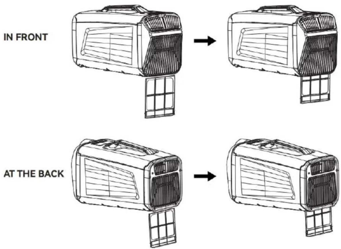
FILTER NETWORK INSTALLATION
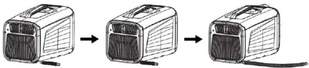
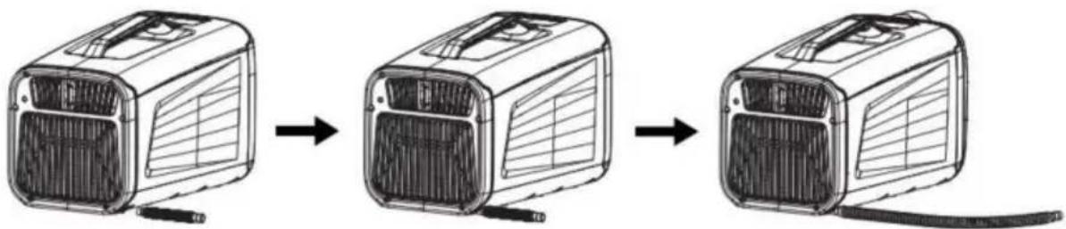
DRAINAGE PIPE INSTALLATION
flowchart
graph LR
    A["Initial heating unit"] --> B["Intermediate heating unit"]
    B --> C["Final cooling unit"]
①Plug in the drain pipe
②To stretch the drain pipe
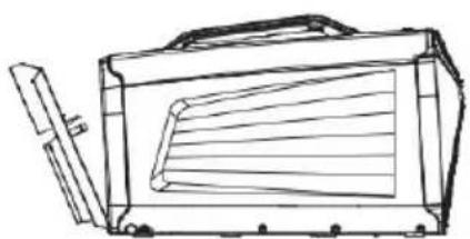
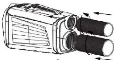
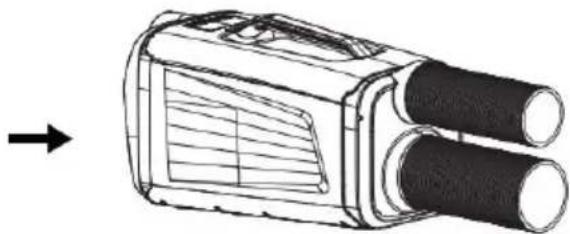
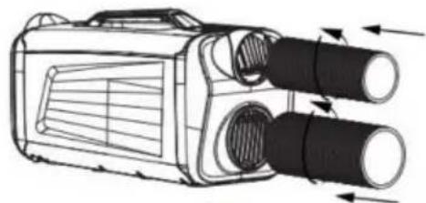
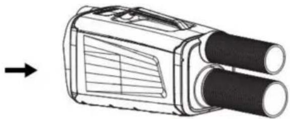
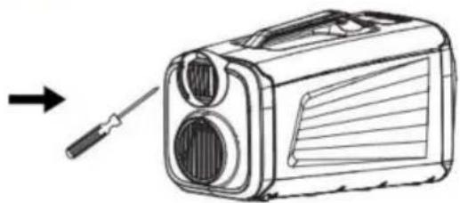
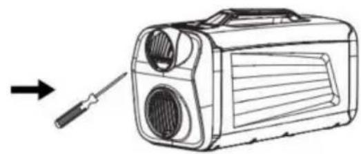
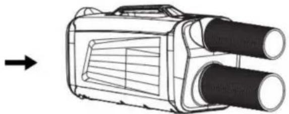
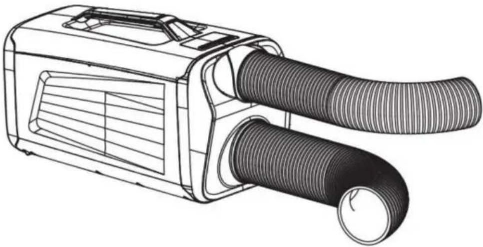
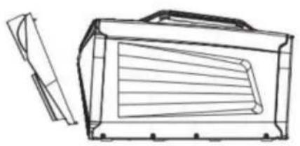
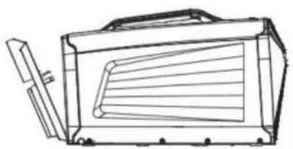
INSTALL THE FRONT AIR EXHAUST PIPE
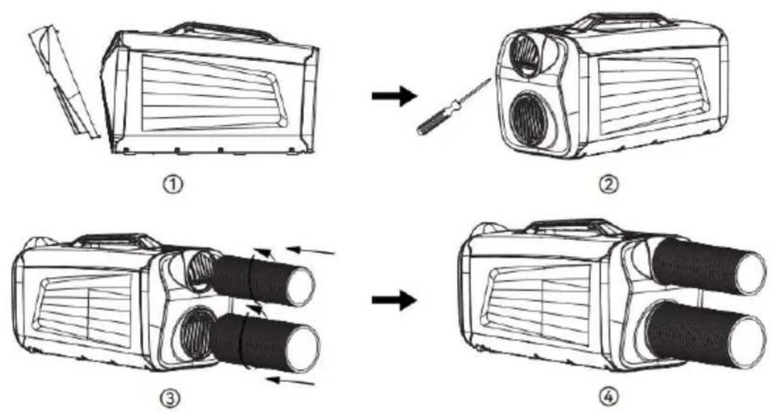
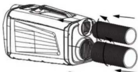
INSTALL THE REAR AIR EXHAUST PIPE
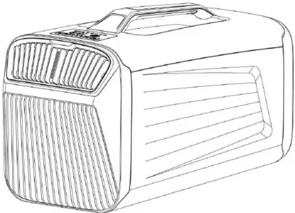
natural_image
Line drawing of a portable radio with a handle and side panel (no text or symbols)①
natural_image
Line drawing of a portable electronic device with a screwdriver and two circular ports, no text or symbols present.②
natural_image
Technical line drawing of a handheld device with two cylindrical tubes and directional arrows indicating flow or movement (no text or symbols)③
natural_image
Line drawing of a handheld device with two cylindrical tubes and a grid-patterned panel, shown with an arrow pointing to it (no text or symbols present)④
natural_image
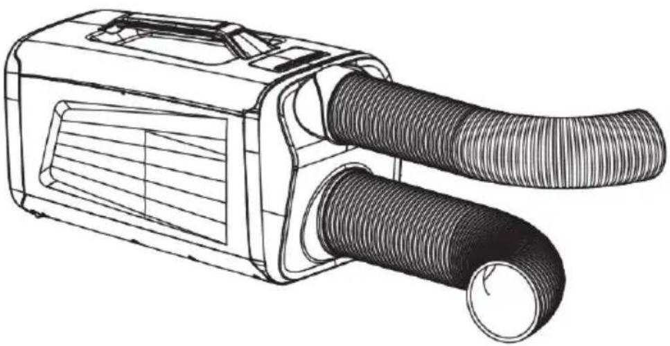
Line drawing of a portable air conditioner unit with coiled tubing (no text or symbols)* No need to connect the exhaust hose when used in large Spaces the field.
* When used for cooling in a small space, use a hose in the opposite direction after connecting the exhaust hose.
TROUBLESHOOTING
| HITCH | CHECK UP | MEASURE |
| The machine cannot be turned on | 1Power-on?2Is the plug allowed to come loose?3Is it turned off?4Is it not turned on?5Do the internal connections fall off? | 1Plug in2Plug in the socket3Reboot4Tap the power switch button twice.5Open the large iron cover and plug in the connecting cable |
| The cooling effect is not good | 1Is the filter screen covered in dust?2Is the air inlet or air outlet blocked?3Is the space too big the doors and Windows are not concerned about good?4Other heating equipment in the room?5Is the exhaust pipe nwell connected or is blocked? | 1Clean the filter2Clean up blocked objects3Use and bed matching mosquito net close the doors and Windows4Remove heating equipment5Reattach or clean the exhaust duct |
| Too much noise and too much vibration | 1Is the machine placed horizontally?2Filter mesh blockage?3Internal refrigerant flow?4Are other objects placed or touched on the host machine?5Internal "zero zero" sound | 1The machine is placed horizontally2Clean the filter3This is a normal phenomenon4Clean up useless things5Find the after-sales department for repair |
| Make water | 1is the host being placed horizontally?22.Gains or drain are blocked3Too much accumulated condensate | 1Place the host machine horizontally2Clean the drains and drains3Remove the condensate from the bucket |
| Wrong with | Whether the machine is useless for a long time the machine is placed a long time, will absorb the smell of furniture, when the machine runs, the smell floats out of machine. | Run the machine for to 5 minutes, and the gas will disappear |
Note:
The real product will differ from that shown. When a repair is needed, please contact the seller or a special repair site professional
MAINTAIN SERVICE
Statement:
① Before cleaning, determine that the machine is not powered on.
② Do not use gasoline and other chemical solvents to clean the ma
③ Do not clean directly with water.
④ If the machine is damaged, please contact the local retailer or repair center.
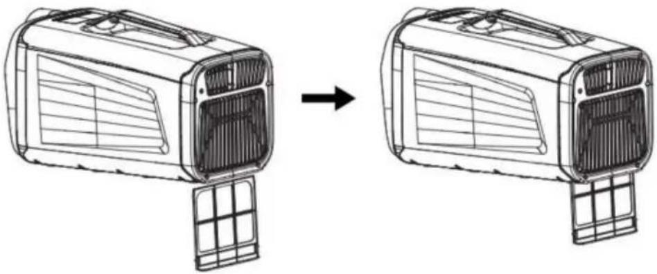
Screen
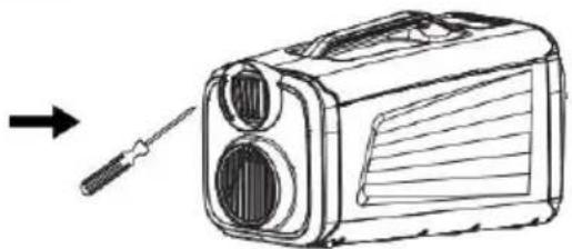
The filters were washed once a month, Method: As shown in the figure use a small cross screwdriver to break the filter fixing screw, pull out filter and then soak it in 40°C warm water mixed with neutral lotion, the debris on the filter with a brush, and put it in a cool place. The filter in the original position again and fix it with screws.
Surface cleaning
Wipe with a neutral lotion or alcohol and wet cloth, and then dry with cloth.
Save method:
Save at the end of the season
① Shut down, unplug the power supply.
② Wipe the surface of the machine with a damp cloth, and then dr a dry cloth.
③ Roll up the power cord with a rope.
④ Slant the machine slightly to the side with the leakage hole and for half an hour until all the residual condensed water in the machine flows out.
⑤ Cover the machine with plastic bags and put it in a dry place.
VEVOR®
TOUGH TOOLS, HALF PRICE
Technical Support and E-Warranty Certificate
www.vevor.com/support
VEVOR®
TOUGH TOOLS, HALF PRICE
natural_image
Line drawing of a portable air conditioner unit (no text or symbols)BESOIN D'AIDE ? CONTACTEZ-NOUS !
Machine Translated by Google
Machine Translated by Google
natural_image
Diagram showing a vehicle air vent before and after assembly, with no text or symbols present.AT THE BACK

natural_image
Line drawing of a car air vent assembly before and after assembly (no text or symbols)DRAINAGE PIPE INSTALLATION

flowchart
graph LR
    A["Vent with fan blade"] --> B["Car panel with ventilation duct"]
    B --> C["Car panel with cable"]
①Plug in the drain pipe
②To stretch the drain pipe
AIR EXHAUST PIPE INSTALLATION
INSTALL THE FRONT AIR EXHAUST PIPE

natural_image
Line drawing of a box with internal compartments and a separate side view (no text or symbols)①

natural_image
Line drawing of a portable radio with a screwdriver inserted, showing no text or symbols②
natural_image
Technical line drawing of a vehicle's front-mounted air duct system with cooling fins and exhaust pipes (no text or symbols)③

natural_image
Technical line drawing of a vehicle-mounted device with two cylindrical components, showing airflow direction (no text or symbols)④
INSTALL THE REAR AIR EXHAUST PIPE

natural_image
Line drawing of a portable electronic device with ventilation slots and a handle (no text or symbols)①

natural_image
Line drawing of a portable radio with a screwdriver, showing no text or symbols②

natural_image
Technical line drawing of a portable electronic device with two cylindrical tubes and ventilation slots (no text or symbols)③
natural_image
Technical line drawing of a mechanical device with two cylindrical components and a left-pointing arrow (no text or symbols)④

natural_image
Line drawing of a portable air conditioner unit with coiled tubing (no text or symbols)www.vevor.com/support
VEVOR®
TOUGH TOOLS, HALF PRICE
natural_image
Line drawing of a portable air conditioner unit (no text or symbols)BRAUCHEN SIE HILFE? KONTAKTIEREN SIE UNS!
Machine Translated by Google
[Ein/Aus]-Taste
natural_image
Diagram showing a vehicle air vent before and after assembly, with no text or symbols present.AT THE BACK
![Vevor IOG-1 - [Ein/Aus]-Taste - 1](/content/2026/04/735619/images/60a825af5635e5ac3b0a8fe9f3763e6fdafc1551ec26265ce527f095a79934b3.jpg)
natural_image
Line drawing of a car air vent assembly before and after assembly (no text or symbols)DRAINAGE PIPE INSTALLATION

flowchart
graph LR
    A["Vent with fan blade"] --> B["Car panel with ventilation duct"]
    B --> C["Car panel with cable"]
①Plug in the drain pipe
②To stretch the drain pipe
AIR EXHAUST PIPE INSTALLATION
INSTALL THE FRONT AIR EXHAUST PIPE

natural_image
Line drawing of a box with internal compartments and a separate side view (no text or symbols)①

natural_image
Line drawing of a portable radio with a screwdriver inserted, showing no text or symbols②

natural_image
Technical line drawing of a vehicle's front-mounted air duct system with cooling fins and exhaust pipes (no text or symbols)③

natural_image
Technical line drawing of a vehicle-mounted device with two cylindrical components, showing airflow direction (no text or symbols)④
INSTALL THE REAR AIR EXHAUST PIPE

natural_image
Line drawing of a portable electronic device with ventilation slots and a handle (no text or symbols)①

natural_image
Line drawing of a portable radio with a screwdriver, showing no text or symbols②

natural_image
Technical line drawing of a portable electronic device with two cylindrical tubes and ventilation slots (no text or symbols)③

natural_image
Technical line drawing of a mechanical device with two cylindrical components and a left-pointing arrow (no text or symbols)④

natural_image
Line drawing of a portable air conditioner unit with coiled tubing (no text or symbols)www.vevor.com/support
VEVOR®
TOUGH TOOLS, HALF PRICE
natural_image
Line drawing of a portable air conditioner unit (no text or symbols)Tasto [On/Off].
natural_image
Diagram showing a vehicle air vent before and after assembly, with no text or symbols present.AT THE BACK
![Vevor IOG-1 - Tasto [On/Off]. - 1](/content/2026/04/735619/images/cff077c44b7f962740dcb5bf6ec38281649b536f8f32433056c12fc5648e01f3.jpg)
natural_image
Line drawing of a car air vent assembly before and after assembly (no text or symbols)DRAINAGE PIPE INSTALLATION
flowchart
graph LR
    A["Vent with fan blade"] --> B["Car panel with ventilation duct"]
    B --> C["Car panel with cable"]
①Plug in the drain pipe
②To stretch the drain pipe
AIR EXHAUST PIPE INSTALLATION
INSTALL THE FRONT AIR EXHAUST PIPE

natural_image
Line drawing of a portable electronic device with ventilation slots and a separate handle (no text or symbols)①

natural_image
Line drawing of a portable radio with a screwdriver inserted, showing no text or symbols②

natural_image
Technical line drawing of a vehicle's front-mounted air duct system with cooling fins and exhaust pipes (no text or symbols)③

natural_image
Technical line drawing of a vehicle-mounted device with two cylindrical components, showing airflow direction (no text or symbols)④
INSTALL THE REAR AIR EXHAUST PIPE

natural_image
Line drawing of a portable electronic device with ventilation slots and a handle (no text or symbols)①

natural_image
Line drawing of a portable radio with a screwdriver, showing no text or symbols②
natural_image
Technical line drawing of a portable electronic device with two cylindrical tubes and ventilation slots (no text or symbols)③

natural_image
Technical line drawing of a mechanical device with two cylindrical components and a left-pointing arrow (no text or symbols)④

natural_image
Line drawing of a portable air conditioner unit with coiled tubing (no text or symbols)www.vevor.com/support
VEVOR®
TOUGH TOOLS, HALF PRICE
natural_image
Line drawing of a portable air conditioner unit (no text or symbols)¿NECESITAS AYUDA?
Machine Translated by Google
Tecla [Encendido/Apagado]
Presione la tecla [on/off] para iniciar y presione la tecla [on/off] para ingresar al modo de espera;
Tecla [Modo]
natural_image
Diagram showing a vehicle air vent before and after assembly, with no text or symbols present.AT THE BACK
natural_image
Line drawing of a car air vent assembly before and after assembly (no text or symbols)DRAINAGE PIPE INSTALLATION

flowchart
graph LR
    A["Vent with fan blade"] --> B["Car panel with ventilation duct"]
    B --> C["Car panel with cable"]
①Plug in the drain pipe
②To stretch the drain pipe
AIR EXHAUST PIPE INSTALLATION
INSTALL THE FRONT AIR EXHAUST PIPE

natural_image
Line drawing of a portable electronic device with ventilation slots and a separate handle (no text or symbols)①

natural_image
Line drawing of a portable radio with a screwdriver inserted, showing no text or symbols②

natural_image
Technical line drawing of a vehicle's air intake manifold with cooling fins and exhaust pipes (no text or symbols)③

natural_image
Technical line drawing of a vehicle-mounted device with two cylindrical components, showing airflow direction (no text or symbols)④
INSTALL THE REAR AIR EXHAUST PIPE

natural_image
Line drawing of a portable electronic device with ventilation slots and a handle (no text or symbols)①
natural_image
Line drawing of a portable radio with a screwdriver, showing no text or symbols②

natural_image
Technical line drawing of a portable electronic device with two cylindrical tubes and ventilation slots (no text or symbols)③

natural_image
Technical line drawing of a mechanical device with two cylindrical components and an arrow indicating direction (no text or symbols)④

natural_image
Line drawing of a portable air conditioner unit with coiled tubing (no text or symbols)www.vevor.com/support
VEVOR®
TOUGH TOOLS, HALF PRICE
natural_image
Line drawing of a portable air conditioner unit (no text or symbols)Machine Translated by Google
Klawisz [Wł./Wył.].
natural_image
Diagram showing a vehicle air vent before and after assembly, with no text or symbols present.AT THE BACK

natural_image
Line drawing of a car air vent assembly before and after assembly (no text or symbols)DRAINAGE PIPE INSTALLATION

flowchart
graph LR
    A["Vent with fan blade"] --> B["Car panel with ventilation duct"]
    B --> C["Car panel with cable"]
①Plug in the drain pipe
②To stretch the drain pipe
AIR EXHAUST PIPE INSTALLATION
INSTALL THE FRONT AIR EXHAUST PIPE

natural_image
Line drawing of a portable electronic device with ventilation slots and a separate handle (no text or symbols)①
natural_image
Line drawing of a portable radio device with a screwdriver inserted, showing no text or symbols.②

natural_image
Technical line drawing of a vehicle's air intake manifold with cooling fins and exhaust pipes (no text or symbols)③
natural_image
Technical line drawing of a vehicle-mounted device with two cylindrical components, showing airflow direction (no text or symbols)④
INSTALL THE REAR AIR EXHAUST PIPE

natural_image
Line drawing of a portable electronic device with ventilation slots and a handle (no text or symbols)①

natural_image
Line drawing of a portable radio with a screwdriver, showing no text or symbols②

natural_image
Technical line drawing of a portable electronic device with two cylindrical tubes and ventilation slots (no text or symbols)③

natural_image
Technical line drawing of a mechanical device with two cylindrical components and a left-pointing arrow (no text or symbols)④
natural_image
Line drawing of a portable air conditioner unit with coiled tubing (no text or symbols)*
www.vevor.com/support
VEVOR®
TOUGH TOOLS, HALF PRICE
Technische ondersteuning en e-garantiecertificaat www.vevor.com/support
DRAAGBARE AIRCONDITIONER
MODEL:IOG-1
natural_image
Line drawing of a portable air conditioner unit (no text or symbols)HULP NODIG?
[Aan / Uit]-toets
natural_image
Diagram showing a vehicle air vent before and after assembly, with no text or symbols present.AT THE BACK
![Vevor IOG-1 - [Aan / Uit]-toets - 1](/content/2026/04/735619/images/72fde8e38204cb623096dbdc636ace4fc86d5c08f8e8e14517f7dac7872149d0.jpg)
natural_image
Line drawing of a car air vent assembly before and after assembly (no text or symbols)DRAINAGE PIPE INSTALLATION

flowchart
graph LR
    A["Vent with fan blade"] --> B["Car panel with ventilation duct"]
    B --> C["Car panel with cable"]
①Plug in the drain pipe
②To stretch the drain pipe
AIR EXHAUST PIPE INSTALLATION
INSTALL THE FRONT AIR EXHAUST PIPE

natural_image
Line drawing of a box with internal compartments and a separate side view (no text or symbols)①

natural_image
Line drawing of a portable radio with a screwdriver inserted, showing no text or symbols②

natural_image
Technical line drawing of a vehicle's front-mounted air duct system with cooling fins and exhaust pipes (no text or symbols)③

natural_image
Technical line drawing of a vehicle-mounted device with two cylindrical components, showing airflow direction (no text or symbols)④
INSTALL THE REAR AIR EXHAUST PIPE

natural_image
Line drawing of a portable electronic device with ventilation slots and a handle (no text or symbols)①

natural_image
Line drawing of a portable radio with a screwdriver, showing no text or symbols②

natural_image
Technical line drawing of a portable electronic device with two cylindrical tubes and ventilation slots (no text or symbols)③

natural_image
Technical line drawing of a mechanical device with two cylindrical components and a left-pointing arrow (no text or symbols)④

natural_image
Line drawing of a portable air conditioner unit with coiled tubing (no text or symbols)natural_image
Line drawing of a portable air conditioner unit (no text or symbols)BEHÖVER HJÄLP?
Knappen [På/Av]
natural_image
Diagram showing a vehicle air vent before and after assembly, with no text or symbols present.AT THE BACK
![Vevor IOG-1 - Knappen [På/Av] - 1](/content/2026/04/735619/images/6e967810d294df2e6069f8fa63a5b9b9d44f6d95798fb196344e5c1636aa8120.jpg)
natural_image
Line drawing of a car air vent assembly before and after assembly (no text or symbols)DRAINAGE PIPE INSTALLATION

flowchart
graph LR
    A["Vent with fan blade"] --> B["Car panel with ventilation duct"]
    B --> C["Car panel with cable"]
①Plug in the drain pipe
②To stretch the drain pipe
AIR EXHAUST PIPE INSTALLATION
INSTALL THE FRONT AIR EXHAUST PIPE
natural_image
Line drawing of a box with internal compartments and a separate side view (no text or symbols)①

natural_image
Line drawing of a portable radio with a screwdriver inserted, showing no text or symbols②

natural_image
Technical line drawing of a vehicle's front-mounted air duct system with cooling fins and exhaust pipes (no text or symbols)③

natural_image
Technical line drawing of a vehicle-mounted device with two cylindrical components, showing airflow direction (no text or symbols)④
INSTALL THE REAR AIR EXHAUST PIPE
natural_image
Line drawing of a portable electronic device with ventilation slots and a handle (no text or symbols)①

natural_image
Line drawing of a portable radio with a screwdriver, showing no text or symbols②

natural_image
Technical line drawing of a portable electronic device with two cylindrical tubes and ventilation slots (no text or symbols)③

natural_image
Technical line drawing of a mechanical device with two cylindrical components and a left-pointing arrow (no text or symbols)④

natural_image
Line drawing of a portable air conditioner unit with coiled tubing (no text or symbols)*
www.vevor.com/support