GZB88095 - Mobile base Vevor - Free user manual and instructions
Find the device manual for free GZB88095 Vevor in PDF.

| Product type | Universal mobile base |
| Brand | Vevor |
| Model | GZB88095 |
| Material | Q235 steel |
| Minimum dimensions | 508 x 622 mm (20 x 24.5 inches) |
| Maximum dimensions | 711 x 851 mm (28 x 33.5 inches) |
| Maximum load capacity | 680 kg (1500 lb) |
| Casters | 4 swivel casters of 3 inches (76 mm) |
| Safety locks | Non-slip feet and foot locks |
| Main use | Moving and positioning heavy machinery (drill presses, saws, etc.) |
| Width adjustment | Yes, thanks to telescopic side tubes |
| Package contents | Base parts, casters, hardware, user manual |
| Safety instructions | Do not overload, do not transport people, avoid stairs, lower the levelers before use |
| Maintenance and cleaning | Regularly inspect screws, casters, and welds; avoid prolonged exposure to sunlight |
| Warranty | Technical assistance via www.vevor.com/support |
| Manufacturer | Shanghaimuxinmuyeyouxiangongsi, Shanghai, China |
| EU Importer | E-CrossStu GmbH, Frankfurt am Main, Germany |
| UK Importer | YH CONSULTING LIMITED |
Frequently Asked Questions - GZB88095 Vevor
User questions about GZB88095 Vevor
0 question about this device. Answer the ones you know or ask your own.
Ask a new question about this device
Download the instructions for your Mobile base in PDF format for free! Find your manual GZB88095 - Vevor and take your electronic device back in hand. On this page are published all the documents necessary for the use of your device. GZB88095 by Vevor.
USER MANUAL GZB88095 Vevor
Technical Support and E-Warranty Certificate
www.vevor.com/support
MOBILE BASE
MODEL: GZB88095
We continue to be committed to provide you tools with competitive price. "Save Half", "Half Price" or any other similar expressions used by us only represent of savings you might benefit from buying certain tools with us compared top brands and does not necessarily mean to cover all categories of tools offered are kindly reminded to verify carefully when you are placing an order with us actually saving half in comparison with the top major brands.
MODEL: GZB88095
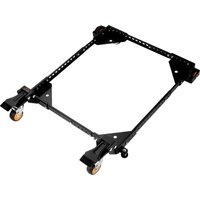
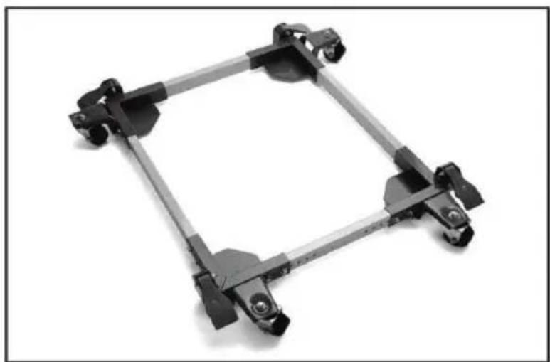
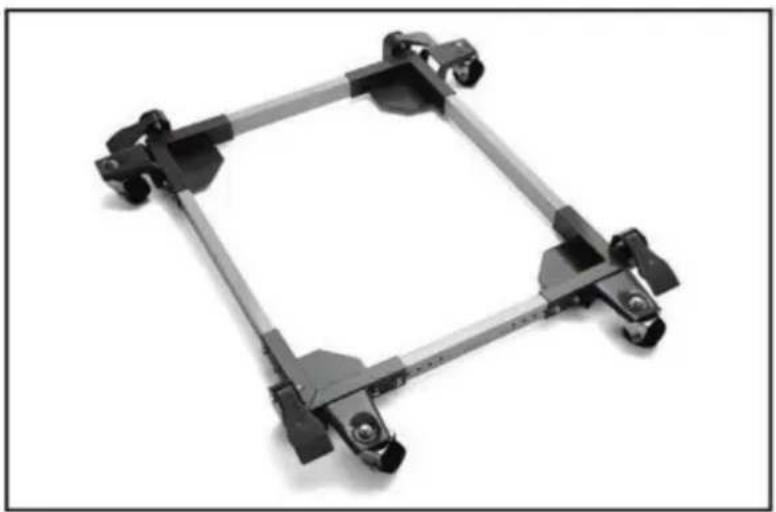
natural_image
Mechanical frame component with wheels and mounting brackets (no text or symbols visible)Photo for reference
NEED HELP? CONTACT US!
Have product questions? Need technical support? Please feel fr contact us:
Technical Support and E-Warranty Certificate www.vevor.com/support
This is the original instruction, please read all manual instruction carefully before operating. VEVOR reserves a clear interpretation user manual. The appearance of the product shall be subject to product you received. Please forgive us that we won't inform you there are any technology or software updates on our product.
SAFETY INSTRUCTIONS

WARNING: Read and understand this manual before assembling, installing, operating, or servicing this product. Failure to follow these warnings and instructions can cause
death, personal injury or damage to valuable property.
- Please do not put it near flammable materials.
- It is forbidden to carry people under any condition.
- This product cannot be used to go up or down stairs.
- Overload is strictly prohibited.
- Don't move too fast when passing pothole areas.
SAVE THESE INSTRUCTIONS
MODEL AND PARAMETERS
Material: Q235
Product size: Minimum 20x24.5 inches, maximum 28x33.5 inches Load capacity: 1500 lbs max.
Note: When adjusting the mobile base to the maximum installation size cannot be used with the maximum load capacity.
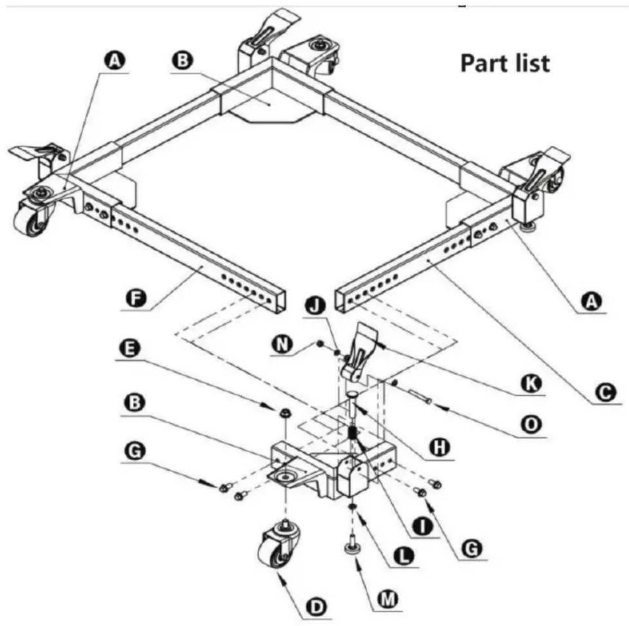
Part list
| Parts List | |||||
| S/N | Description | Qty | S/N | Description | Qty |
| A | Left Corner | 2 | I | Foot Lever Spring | 4 |
| B | Right Corner | 2 | J | M8 Flat Washer | 16 |
| C | Short Side Tube | 2 | K | Foot Lever | 4 |
| D | 3” Swivel Caster | 4 | L | M10 Jam Nut | 4 |
| E | Flange Nut | 4 | M | Rubber Glide Foot | 4 |
| F | Lon9 Side Tube | 2 | N | M8 Nyloc Nut | 4 |
| G | M10x20 Flanged Hex Bolt | 16 | O | 8x60-15Hex Bolt | 4 |
| H | Foot Lever Plunger | 4 | |||
Safety instructions for Mobile Bases
- Be careful when moving to limit any finger pinch points.
- Place base on a level surface and adjust levelers before placing the machine in position. This should keep the machine from rocking, while testing it for stability.
3.3 Test the stability in both the up (on the casters) and the down p Exercise caution when testing the stability of top heavy machines (dril presses, band saws, etc.). - Unplug any power tool before moving or repositioning your tool.
- Always test your set-up for stability and safety after repositioning.
- Care should be taken when planning the orientation of the machine
the Universal Mobile Base. Transfer the weight off of the levelers to casters will result in the machine tilting1/2" toward the fixed wheels. \ positioning top heavy tools such as a drill press or bandsaw, take advantage of the center of gravity, and position so that it will remain while on casters.
- Never use your machine without engaging the floor locks and foot Always lower the machine onto the non-skid levelers before operating.
- When moving, always push the base, not the machine.
Assembly Examples
Be sure to follow safety and Assembly Instructions. Keep in mind the operation of your machine and the effect it has on overall stability.
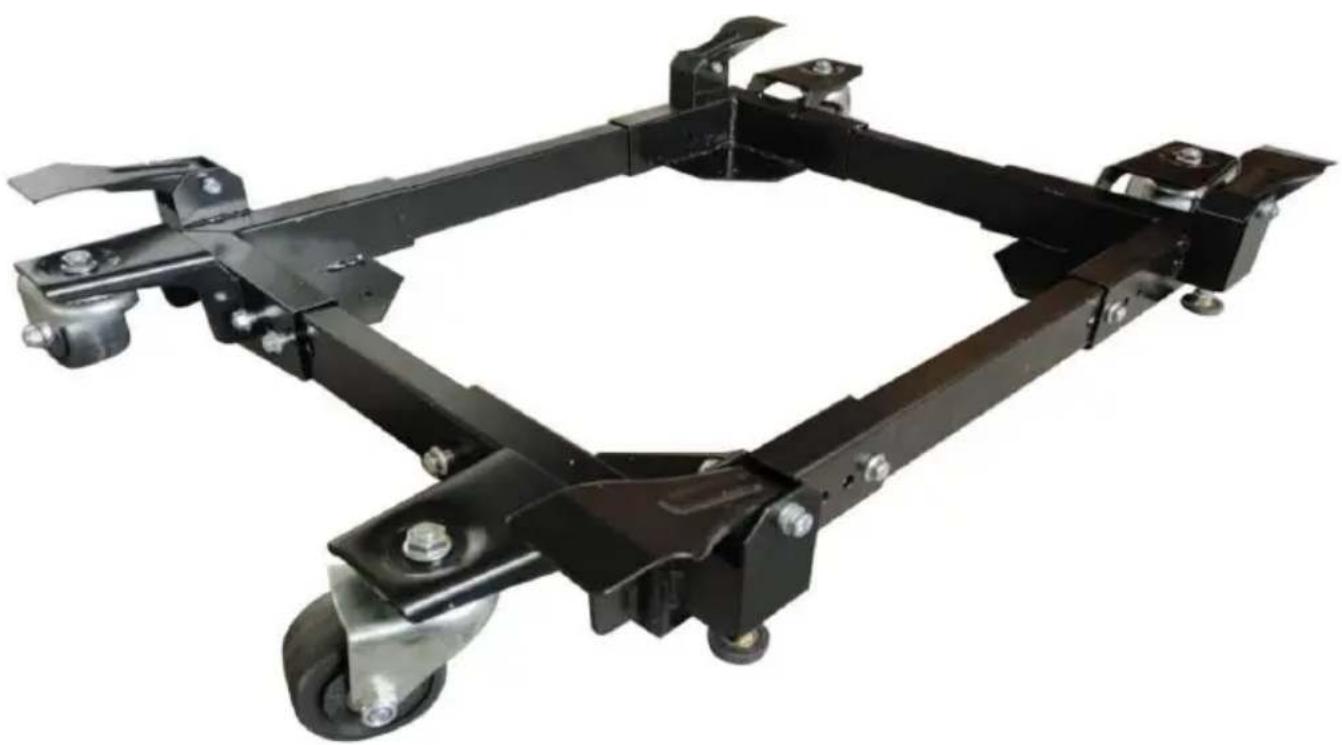
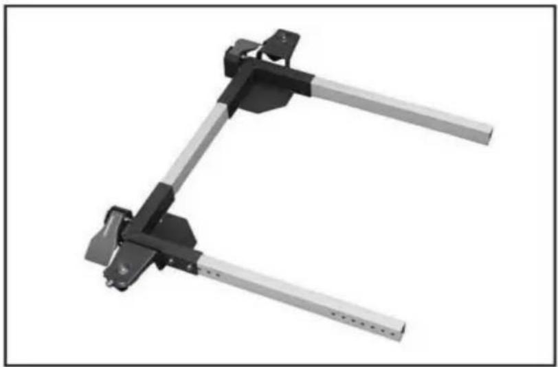
natural_image
Mechanical frame assembly with four vertical supports and a central rectangular frame (no text or symbols visible)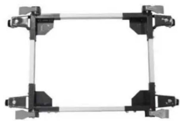
natural_image
Mechanical frame assembly with four vertical supports and a central rectangular frame (no text or symbols visible)A long, narrow base, such as or jointer, would benefit from this arrangement. Most machines may be arranged to the convenience of the user. A short, narrow base, such as found on a drill press or bands may benefit from this arrangement. Due to swivel rotation the base may sit out of level. Rotate the swivel wheel away from the base correct.
Assembly Instructions
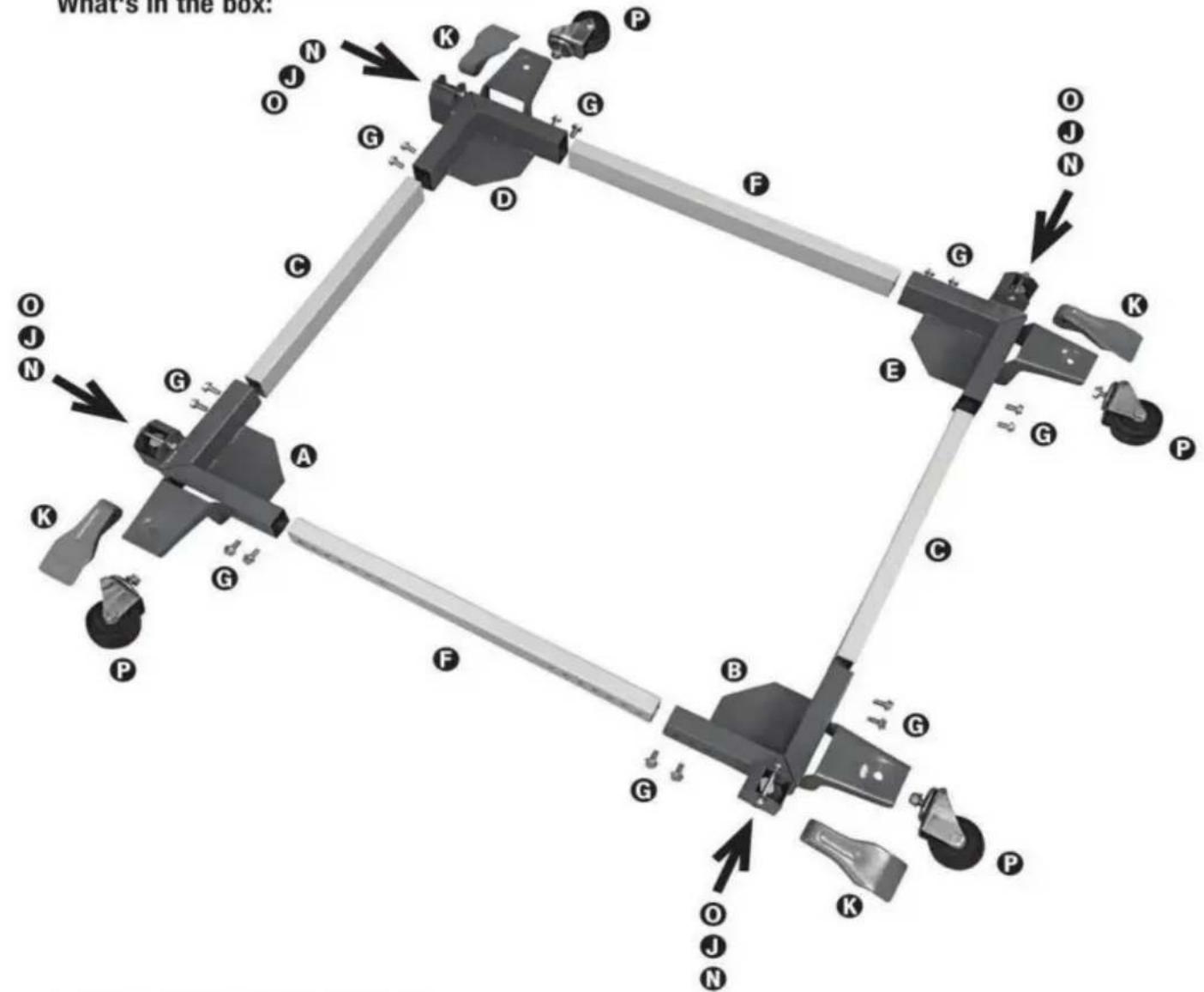
What's in the box:
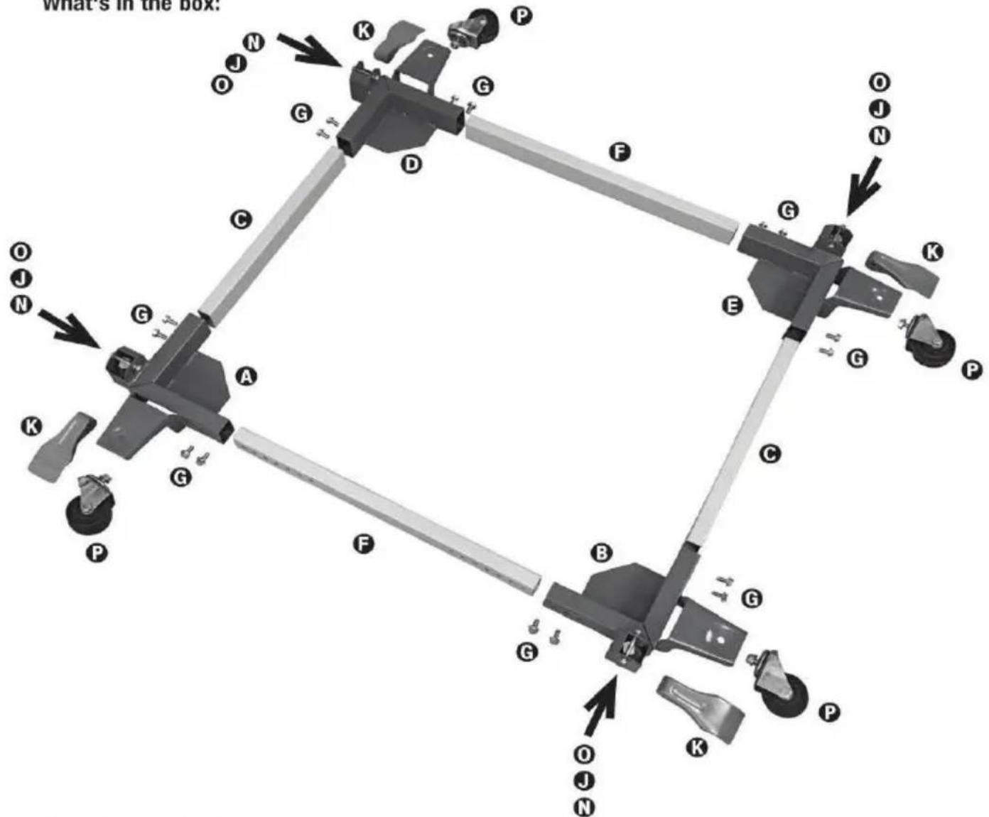
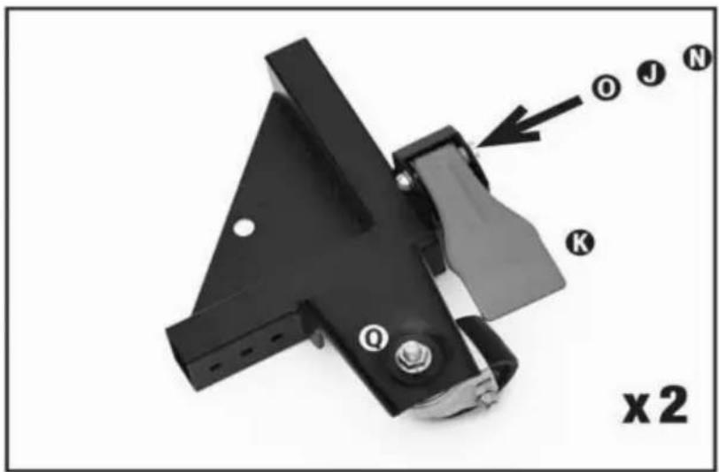
Step 1. Assemble front corners
- Bolt foot lever L to base using part O, J, & N
- Bolt swivel caster to base using part Ⓞ

Step 2. Assemble back corners
- Bolt foot lever L to base using part Ⓓ, ⚡, & Ⓝ
- Bolt swivel caster to base using part ①

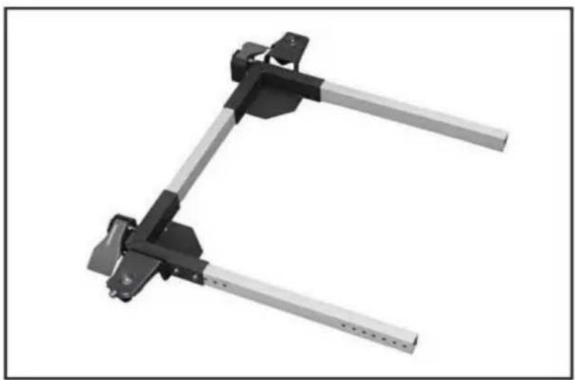
Step 3. Assemble side tubes
- Bolt side tube between the front and back right corners using 4x part G
- Bolt the tube out of the side of the front and back corner using 2x part G each
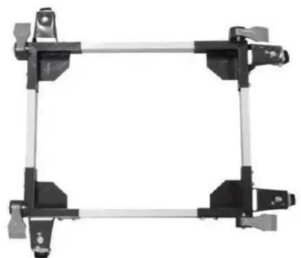
natural_image
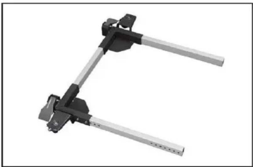
Mechanical clamp bracket with metal frame and mounting bracket (no text or symbols)Step 4. Slide the machine onto the base
- Slide your machine onto the mobile base before connecting the remaining corners
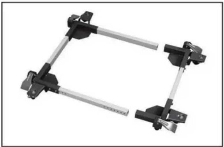
Step 5. Connect the remaining corners
- Bolt side tube between the front and back right corners using 4x part G
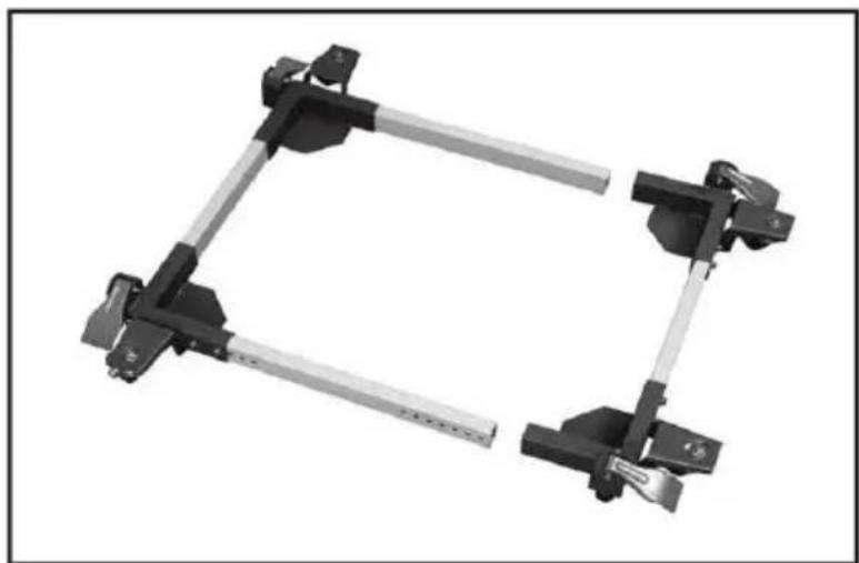
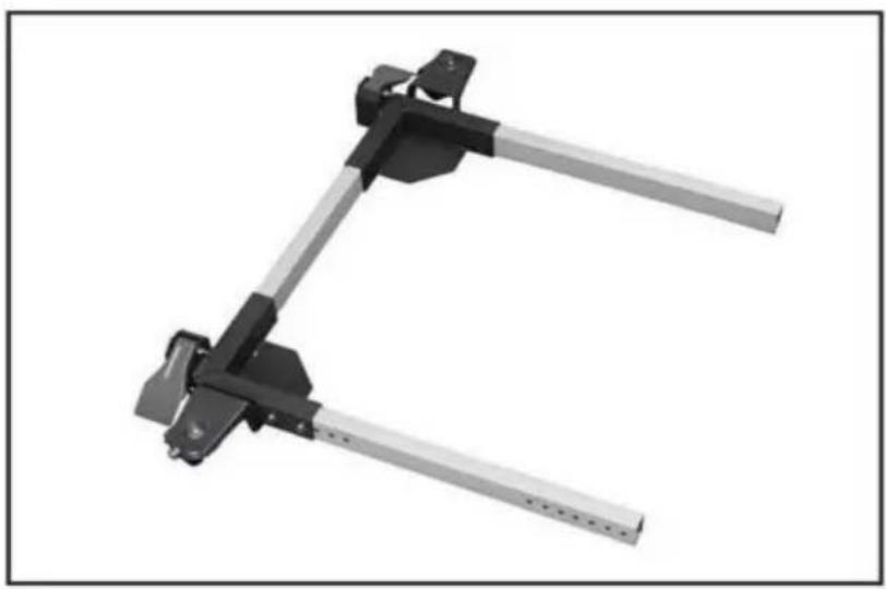
natural_image
Mechanical clamp bracket assembly with two metal clamps (no text or symbols visible)- Slide the left assembly onto the front and back rail - bolt it together using 4x part G
natural_image
Mechanical component with four articulated arms and a central square frame (no text or symbols visible)MAINTENANCE
- Avoid prolonged exposure to the sun to avoid aging.
- Inspect accessories for wear, cracks, and other damage before use, replace defective accessories immediately.
Manufacturer: Shanghaimuxinmuyeyouxiangongsi
Address: Shuangchenglu 803nong11hao1602A-1609shi, baoshanqu, shanghai 200000 CN.
Imported to AUS: SIHAO PTY LTD, 1 ROKEVA STREETEASTWOOD NS 2122 Australia
Imported to USA: Sanven Technology Ltd., Suite 250, 9166 Anaheim Pla Rancho Cucamonga, CA 91730
| EC | REP |
| UK | REP |
E-CrossStu GmbH
Mainzer Landstr.69, 60329 Frankfurt am Ma
YH CONSULTING LIMITED.
C/O YH Consulting Limited Office 147, Centurion H London Road, Staines-upon-Thames, Surrey, TW18 4
VEVOR®
TOUGH TOOLS, HALF PRICE
Technical Support and E-Warranty Certificate www.vevor.com/support
VEVOR®
TOUGH TOOLS, HALF PRICE
natural_image
Mechanical frame component with wheels and mounting brackets (no text or symbols visible)natural_image
Mechanical frame assembly with four vertical supports and a central rectangular frame (no text or symbols visible)natural_image
Mechanical frame assembly with four vertical supports and a central rectangular frame (no text or symbols visible)Assembly Instructions
What's in the box:

Step 1. Assemble front corners
- Bolt foot lever L to base using part Ⓞ, Ⓙ, & ₩
- Bolt swivel caster to base using part Ⓞ

Step 2. Assemble back corners
- Bolt foot lever L to base using part Ⓞ, Ⓙ, & Ⓝ
- Bolt swivel caster to base using part Ⓞ

Step 3. Assemble side tubes
- Bolt side tube between the front and back right corners using 4x part G
- Bolt the tube out of the side of the front and back corner using 2x part © each
natural_image
Mechanical clamp bracket with metal railings and mounting brackets (no text or symbols visible)Step 4. Slide the machine onto the base
- Slide your machine onto the mobile base before connecting the remaining corners
Step 5. Connect the remaining corners
- Bolt side tube between the front and back right corners using 4x part G

natural_image
Mechanical clamp bracket with metal frame and mounting brackets (no text or symbols visible)- Slide the left assembly onto the front and back rail - bolt it together using 4x part G

natural_image
Mechanical frame component with four articulated arms and mounting feet (no text or symbols visible)ENTRETIEN
C/O YH Consulting Limited Bureau 147, Centurion House, London Road, Staines-upon-Thames, Surrey, TW18 4AX
VEVOR®
TOUGH TOOLS, HALF PRICE
www.vevor.com/support
MOBILE BASIS
MODELL: GZB88095
natural_image
Mechanical frame component with wheels and mounting brackets (no text or symbols visible)Foto als Referenz
natural_image
Mechanical frame assembly with four vertical supports and a central rectangular frame (no text or symbols visible)natural_image
Mechanical frame assembly with four vertical supports and a central rectangular frame (no text or symbols visible)Assembly Instructions
What's in the box:

Step 1. Assemble front corners
- Bolt foot lever L to base using part Ⓞ, Ⓙ, & ₩
- Bolt swivel caster to base using part Ⓞ

Step 2. Assemble back corners
- Bolt foot lever L to base using part Ⓞ, Ⓙ, & Ⓝ
- Bolt swivel caster to base using part Ⓞ

Step 3. Assemble side tubes
- Bolt side tube between the front and back right corners using 4x part G
- Bolt the tube out of the side of the front and back corner using 2x part © each

natural_image
Mechanical clamp bracket with metal railings and mounting brackets (no text or symbols visible)Step 4. Slide the machine onto the base
- Slide your machine onto the mobile base before connecting the remaining corners
Step 5. Connect the remaining corners
- Bolt side tube between the front and back right corners using 4x part G

natural_image
Mechanical clamp bracket with metal frame and mounting brackets (no text or symbols visible)- Slide the left assembly onto the front and back rail - bolt it together using 4x part G

natural_image
Mechanical frame component with four articulated arms and mounting feet (no text or symbols visible)WARTUNG
C/O YH Consulting Limited Office 147, Centurion House,
London Road, Staines-upon-Thames, Surrey, TW18 4AX
VEVOR®
TOUGH TOOLS, HALF PRICE
elettronica www.vevor.com/support
BASE MOBILE
MODELLO: GZB88095
natural_image
Mechanical frame component with wheels and mounting brackets (no text or symbols visible)natural_image
Mechanical frame assembly with four vertical supports and a central rectangular frame (no text or symbols)natural_image
Mechanical frame assembly with four vertical supports and a central rectangular frame (no text or symbols visible)Assembly Instructions
What's in the box:
Step 1. Assemble front corners
- Bolt foot lever L to base using part Ⓞ, Ⓙ, & ₩
- Bolt swivel caster to base using part Ⓞ

Step 2. Assemble back corners
- Bolt foot lever L to base using part Ⓞ, Ⓙ, & ⌊
- Bolt swivel caster to base using part Ⓞ

Step 3. Assemble side tubes
- Bolt side tube between the front and back right corners using 4x part G
- Bolt the tube out of the side of the front and back corner using 2x part G each
natural_image
Mechanical clamp bracket with metal railings and mounting brackets (no text or symbols visible)Step 4. Slide the machine onto the base
- Slide your machine onto the mobile base before connecting the remaining corners
Step 5. Connect the remaining corners
- Bolt side tube between the front and back right corners using 4x part G

natural_image
Mechanical clamp bracket with metal frame and mounting brackets (no text or symbols visible)- Slide the left assembly onto the front and back rail - bolt it together using 4x part G

natural_image
Mechanical frame component with four articulated arms and mounting feet (no text or symbols visible)MANUTENZIONE
Importato in AUS: SIHAO PTY LTD, 1 ROKEVA STREETEASTWOOD NSW 2122 Australia
C/O YH Consulting Limited Ufficio 147, Centurion House, London Road, Staines-upon-Thames, Surrey, TW18 4AX
VEVOR®
TOUGH TOOLS, HALF PRICE
natural_image
Mechanical frame component with wheels and mounting brackets (no text or symbols visible)natural_image
Mechanical frame assembly with four vertical supports and a central rectangular frame (no text or symbols visible)natural_image
Mechanical linkage assembly with four vertical supports and a rectangular frame (no text or symbols)Assembly Instructions
What's in the box:

Step 1. Assemble front corners
- Bolt foot lever L to base using part Ⓞ, Ⓙ, & ₩
- Bolt swivel caster to base using part Ⓞ

Step 2. Assemble back corners
- Bolt foot lever L to base using part Ⓞ, Ⓙ, & Ⓝ
- Bolt swivel caster to base using part Ⓞ

Step 3. Assemble side tubes
- Bolt side tube between the front and back right corners using 4x part G
- Bolt the tube out of the side of the front and back corner using 2x part © each

natural_image
Mechanical clamp bracket with metal railings and mounting brackets (no text or symbols visible)Step 4. Slide the machine onto the base
- Slide your machine onto the mobile base before connecting the remaining corners
Step 5. Connect the remaining corners
- Bolt side tube between the front and back right corners using 4x part G

natural_image
Mechanical clamp bracket with metal frame and mounting brackets (no text or symbols visible)- Slide the left assembly onto the front and back rail - bolt it together using 4x part G

natural_image
Mechanical frame component with four articulated arms and mounting feet (no text or symbols visible)MANTENIMIENTO
Importado a AUS: SIHAO PTY LTD, 1 ROKEVA STREETEASTWOOD NSW 2122 Australia
Importado a EE. UU.: Sanven Technology Ltd., Suite 250, 9166 Anaheim Place, Rancho Cucamonga, CA 91730

E-CrossStu GmbH
C/O YH Consulting Limited Oficina 147, Centurion House, London Road, Staines upon Thames, Surrey, TW18 4AX
VEVOR®
TOUGH TOOLS, HALF PRICE
www.vevor.com/support
BAZA MOBILNA
MODEL: GZB88095
natural_image
Mechanical frame component with wheels and mounting brackets (no text or symbols visible)natural_image
Mechanical frame assembly with four vertical supports and a central rectangular frame (no text or symbols visible)natural_image
Mechanical frame assembly with four vertical supports and a central rectangular frame (no text or symbols visible)Assembly Instructions
What's in the box:

Step 1. Assemble front corners
- Bolt foot lever L to base using part Ⓞ, Ⓙ, & ₩
- Bolt swivel caster to base using part Ⓞ

Step 2. Assemble back corners
- Bolt foot lever L to base using part Ⓞ, Ⓙ, & Ⓝ
- Bolt swivel caster to base using part Ⓞ

Step 3. Assemble side tubes
- Bolt side tube between the front and back right corners using 4x part G
- Bolt the tube out of the side of the front and back corner using 2x part © each

natural_image
Mechanical clamp bracket with metal railings and mounting brackets (no text or symbols visible)Step 4. Slide the machine onto the base
- Slide your machine onto the mobile base before connecting the remaining corners
Step 5. Connect the remaining corners
- Bolt side tube between the front and back right corners using 4x part G

natural_image
Mechanical clamp bracket with metal frame and mounting brackets (no text or symbols visible)- Slide the left assembly onto the front and back rail - bolt it together using 4x part G
natural_image
Mechanical frame component with four articulated arms and mounting feet (no text or symbols visible)KONSERWACJA
Import do AUS: SIHAO PTY LTD, 1 ROKEVA STREETEASTWOOD NSW 2122 Australii
Import do USA: Sanven Technology Ltd., Suite 250, 9166 Anaheim Place, Rancho Cucamonga, CA 91730

E-CrossStu GmbH
Mainzer Landstr.69, 60329 Frankfurt nad Menem.

C/O YH Consulting Limited Office 147, Centurion House, London Road, Staines-upon-Thames, Surrey, TW18 4AX
VEVOR®
TOUGH TOOLS, HALF PRICE
www.vevor.com/support
VEVOR®
TOUGH TOOLS, HALF PRICE
www.vevor.com/support
MOBIELE BASIS
MODEL: GZB88095
natural_image
Mechanical frame component with wheels and mounting brackets (no text or symbols visible)Foto ter referentie
HULP NODIG? NEEM CONTACT MET ONS OP!
natural_image
Mechanical frame assembly with four vertical supports and a central rectangular frame (no text or symbols)natural_image
Mechanical frame assembly with four vertical supports and a central rectangular frame (no text or symbols visible)Assembly Instructions
What's in the box:

Step 1. Assemble front corners
- Bolt foot lever L to base using part Ⓞ, Ⓙ, & ₩
- Bolt swivel caster to base using part Ⓞ

Step 2. Assemble back corners
- Bolt foot lever L to base using part Ⓞ, Ⓙ, & Ⓝ
- Bolt swivel caster to base using part Ⓞ

Step 3. Assemble side tubes
- Bolt side tube between the front and back right corners using 4x part G
- Bolt the tube out of the side of the front and back corner using 2x part G each

natural_image
Mechanical clamp bracket with metal railings and mounting brackets (no text or symbols visible)Step 4. Slide the machine onto the base
- Slide your machine onto the mobile base before connecting the remaining corners
Step 5. Connect the remaining corners
- Bolt side tube between the front and back right corners using 4x part G

natural_image
Mechanical clamp bracket with metal frame and mounting brackets (no text or symbols visible)- Slide the left assembly onto the front and back rail - bolt it together using 4x part G

natural_image
Mechanical frame component with four articulated arms and mounting feet (no text or symbols visible)ONDERHOUD
C/O YH Consulting Limited Kantoor 147, Centurion House, London Road, Staines-upon-Thames, Surrey, TW18 4AX
VEVOR®
TOUGH TOOLS, HALF PRICE
Technische ondersteuning en e- garantiecertificaat www.vevor.com/support
VEVOR®
TOUGH TOOLS, HALF PRICE
www.vevor.com/support
MOBIL BAS
MODELL: GZB88095
natural_image
Mechanical frame component with wheels and mounting brackets (no text or symbols visible)Foto för referens
BEHÖVER HJÄLP? KONTAKTA OSS!
natural_image
Mechanical frame assembly with four vertical supports and a central rectangular frame (no text or symbols)natural_image
Mechanical frame assembly with four vertical supports and a central rectangular frame (no text or symbols visible)Assembly Instructions
What's in the box:

Step 1. Assemble front corners
- Bolt foot lever L to base using part Ⓞ, Ⓙ, & ₩
- Bolt swivel caster to base using part Ⓞ

Step 2. Assemble back corners
- Bolt foot lever L to base using part Ⓞ, Ⓙ, & Ⓝ
- Bolt swivel caster to base using part Ⓞ
Step 3. Assemble side tubes
- Bolt side tube between the front and back right corners using 4x part G
- Bolt the tube out of the side of the front and back corner using 2x part G each
natural_image
Mechanical clamp bracket with metal railings and mounting brackets (no text or symbols visible)Step 4. Slide the machine onto the base
- Slide your machine onto the mobile base before connecting the remaining corners
Step 5. Connect the remaining corners
- Bolt side tube between the front and back right corners using 4x part G
natural_image
Mechanical clamp bracket with metal frame and mounting brackets (no text or symbols visible)- Slide the left assembly onto the front and back rail - bolt it together using 4x part G

natural_image
Mechanical frame component with four articulated arms and mounting feet (no text or symbols visible)UNDERHÅLL
C/O YH Consulting Limited Office 147, Centurion House, London Road, Staines-upon-Thames, Surrey, TW18 4AX
VEVOR®
TOUGH TOOLS, HALF PRICE