GZB88093 - Mobile base Vevor - Free user manual and instructions
Find the device manual for free GZB88093 Vevor in PDF.

| Product Type | Mobile Base for Tools |
| Brand | Vevor |
| Model | GZB88093 |
| Material | Q235 (quality steel) |
| Base Dimensions (adjustable) | From 12 x 12 inches to 36 x 36 inches |
| Maximum Load | 650 lb (approx. 295 kg) |
| Item Weight | Approx. 15 kg (estimated) |
| Power Supply | None (manual device) |
| Primary Function | Mobile support for machines and equipment |
| Recommended Use | Workshop, garage, warehouse |
| Size Adjustment | Adjustable range from 12 to 36 inches |
| Maintenance and Cleaning | Clean with a damp cloth, avoid prolonged sun exposure |
| Safety | Do not transport people, do not go up/down stairs, avoid overloading |
| Spare Parts and Repairability | Contact the manufacturer or www.vevor.com/support for spare parts |
| Warranty | Electronic warranty certificate available online |
| Manufacturer | Shanghai Muxin Muye Co., Ltd., Shanghai, China |
| USA Importer | Sanven Technology Ltd., Rancho Cucamonga, CA 91730 |
| CE Representative | E-CrossStu GmbH, Frankfurt am Main, Germany |
| UK Representative | YH CONSULTING LIMITED |
| Package Contents | Mobile base, assembly instructions, fastening accessories |
Frequently Asked Questions - GZB88093 Vevor
User questions about GZB88093 Vevor
0 question about this device. Answer the ones you know or ask your own.
Ask a new question about this device
Download the instructions for your Mobile base in PDF format for free! Find your manual GZB88093 - Vevor and take your electronic device back in hand. On this page are published all the documents necessary for the use of your device. GZB88093 by Vevor.
USER MANUAL GZB88093 Vevor
Technical Support and E-Warranty Certificate
www.vevor.com/support
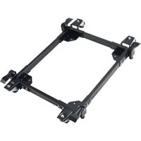
MOBILE BASE
MODEL: GZB88093
We continue to be committed to provide you tools with competitive price. "Save Half", "Half Price" or any other similar expressions used by us only represent of savings you might benefit from buying certain tools with us compared top brands and does not necessarily mean to cover all categories of tools offered are kindly reminded to verify carefully when you are placing an order with us actually saving half in comparison with the top major brands.
MODEL: GZB88093
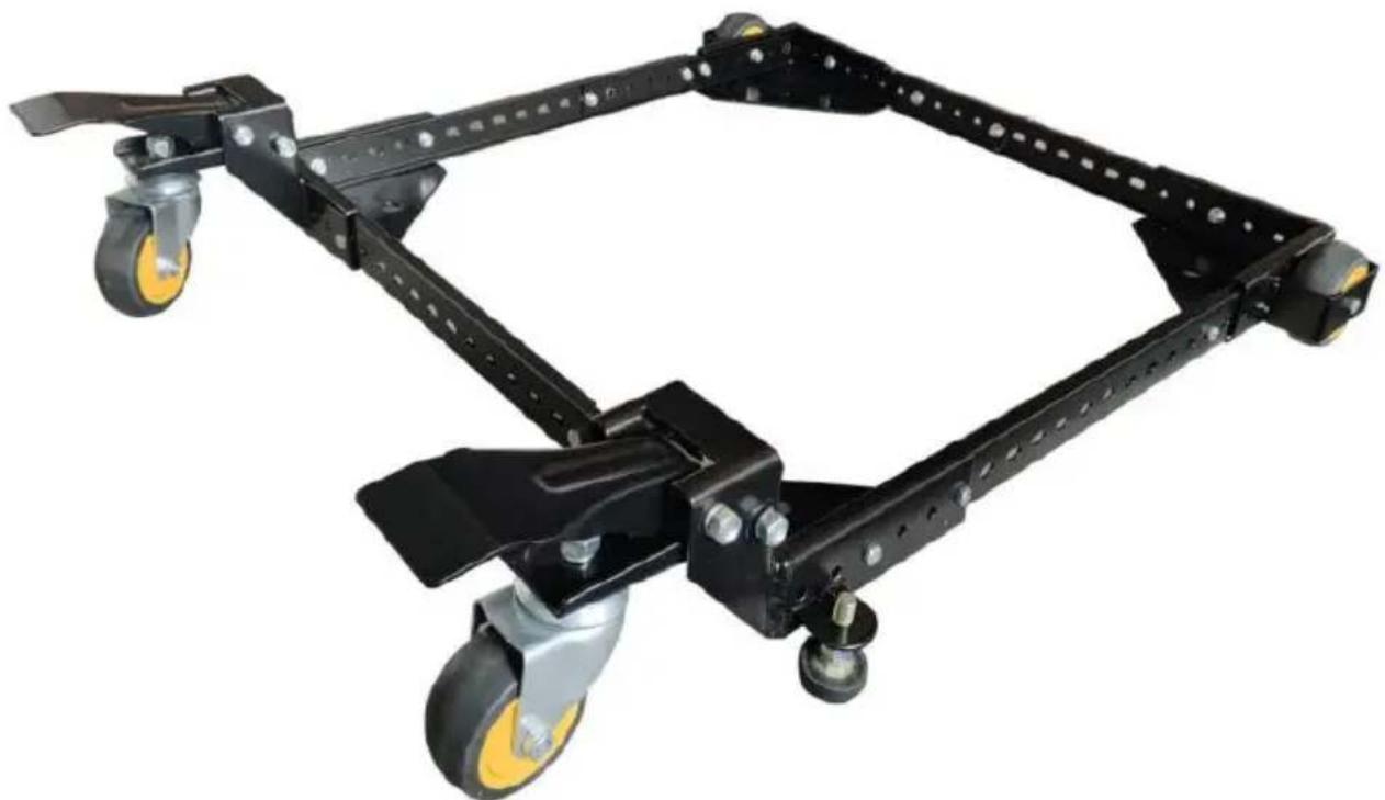
natural_image
Mechanical frame with black and yellow wheels, no visible text or symbolsPhoto for reference
NEED HELP? CONTACT US!
Have product questions? Need technical support? Please feel fr contact us:
Technical Support and E-Warranty Certificate www.vevor.com/support
This is the original instruction, please read all manual instruction carefully before operating. VEVOR reserves a clear interpretation user manual. The appearance of the product shall be subject to product you received. Please forgive us that we won't inform you there are any technology or software updates on our product.
SAFETY INSTRUCTIONS

WARNING: Read and understand this manual before assembling, installing, operating, or servicing this product.
Failure to follow these warnings and instructions can caus
death, personal injury, or damage to valuable property.
- Please do not put it near flammable materials.
- It is forbidden to carry people under any condition.
- This product cannot be used to go up or down stairs.
- Overload is strictly prohibited.
- Don't move too fast when passing pothole areas.
SAVE THESE INSTRUCTIONS
MODEL AND PARAMETERS
| Model | GZB88093 |
| Material | Q235 |
| Base size adjustment range | 12x12 inches up to 36x36 inches |
| maximum load | 650 lbs |
Part list:

| Parts List | |||||
| S/N | Description | Qty | S/N | Description | Qty |
| A | FRONT LEFT CORNER | 1 | L | M10 LOCK WASHER | 2 |
| B | FRONT RIGHT CORNER | 1 | M | M8 LOCK WASHER | 4 |
| C | Short SIDE RAIL | 4 | N | M10 NUT | 4 |
| D | Lon9 SIDE RAIL | 4 | O | M8 NUT | 4 |
| E | REAR LEFT CORNER | 1 | P | M6 FLANGE NUT | 26 |
| F | REAR RIGHT CORNER | 1 | Q | M6-12 HEX BOLT | 24 |
| G | FOOT LEVER | 2 | R | NYLON WHEEL BUSHING | 2 |
| H | SWIVEL PLATE | 2 | S | M6-55 AXLE BOLT | 2 |
| I | 3" SWIVEL CASTER | 2 | T | M8-85 CARRIAGE BOLT | 4 |
| J | 3" WHEEL | 2 | U | NYLON FOOT LEVER BUSHIN | 4 |
| K | RUBBER GLIDE FOOT | 2 | |||
Assembly Examples
Be sure to follow Safety and Assembly Instructions. Keep in mind the actual operation of your machine and the effect it has on overall stability.
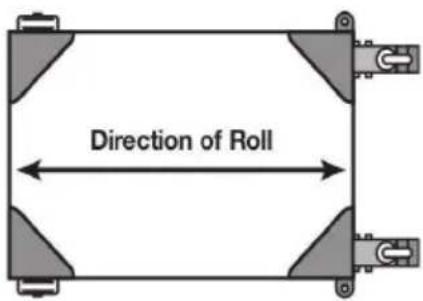
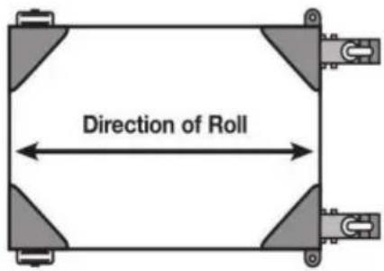
A long, narrow base, such as on a jointer, would benefit from this arrangement. Most machines may be arranged to the convenience of the user.
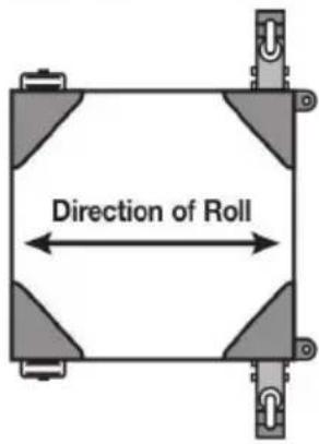
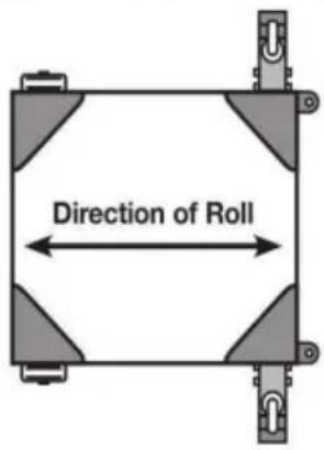
A short, narrow base, such as found on a drill press or bandsaw, may benefit from this arrangement. Due to swivel rotation, base may sit out of level. Rotate swivel wheel away from base to correct.
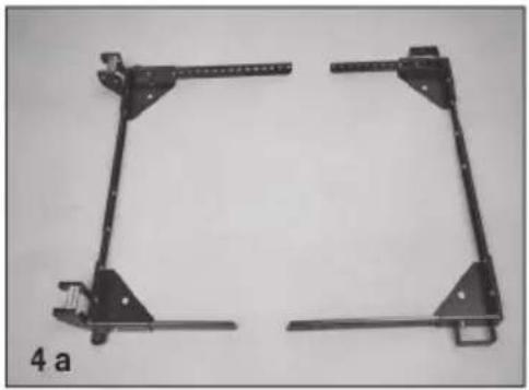
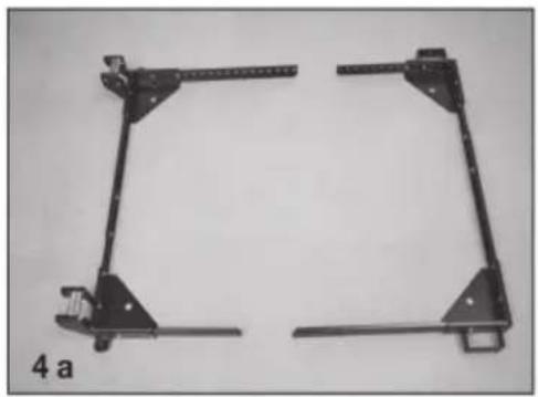
- Select and arrange the Corners and the Side Rails as necessary to assemble the base to your machine's footprint. Position Side Rails into corners as far as is practical.
a. Below is a standard arrangement, but many different arrangements are possible. You can use 1, 2, or 3 rails on either side.
b. To expand the functionality of this mobile base on larger machine's, purchase additional rails online at http://www.boratool.com/rail-kit-w-hardware-pm1000-htc2000
- Bolt the Side Rails to the corners and each other using these simple rules:
a. All connections require the use of (2) M6-12 bolts and (2) M6 nuts at each end of the connections
Note: Insert bolts so that the nuts are on the INSIDE of the mobile base.
- Re-check dimensions with the tape measure, then tighten all bolts and nuts. If you are building a square configuration the measurements between diagonal corners should be relatively close.
natural_image
Mechanical bracket assembly with four metal parts, no visible text or symbols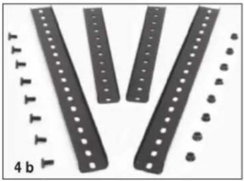
natural_image
Close-up of black plastic strips with circular holes and small circular indentations, labeled '4 b' (no text or symbols on the strips themselves)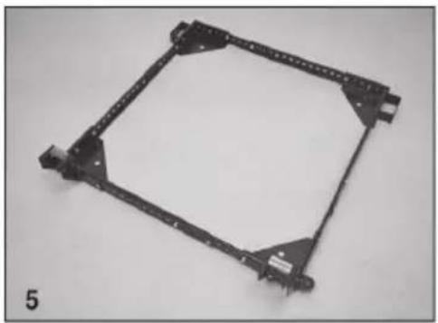
natural_image
Mechanical component with four mounting brackets and a central square frame (no text or symbols visible)Attaching Wheels and Casters
-
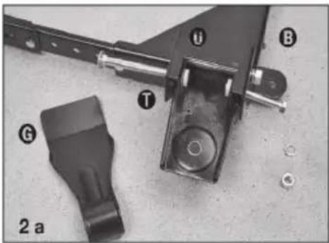
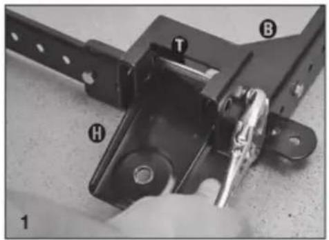
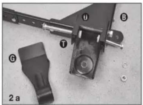
Attach swivel plate “H” to the Front Right corner “B” using M8-85 carriage bolt “T”, M8 lock washer “M”, and M8 nut “O”.
-
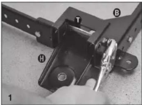
Attach foot lever "C" to the Front Right corner "B".
a. Slide the M8-85 carriage bolt "⑦" through the hole on the inside of the corner, hang a nylon foot lever bushing "①" on the end of the bolt. Insert an extra bolt into the hole from the outside of the corner just far enough to act as a "hanger" for the other nylon bushing.
b. Carefully slide the foot lever into place between the nylon bushings.
c. Push the carriage bolt through the foot lever, nylon washers, and opposite side of the corner. Secure it using the M8 lock washer "M".
- Attach swivel caster "①" to swivel plate "H" using M10 lock washer "L" and M10 nut "M".
natural_image
Close-up of mechanical components with numbered labels (i, B, T, G) and a base labeled 2a, no readable text or symbols beyond labels.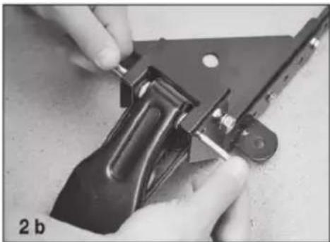
natural_image
Close-up of hands using a tool to adjust or install a metal clip (no visible text or symbols)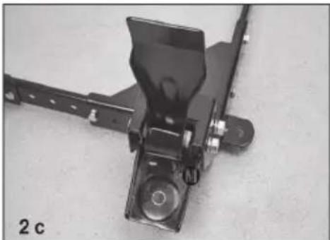
natural_image
Mechanical component with black bracket and mounting bracket, labeled '2 c' (no text or symbols on the object itself)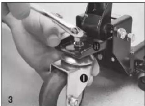
natural_image
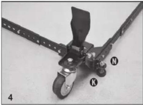
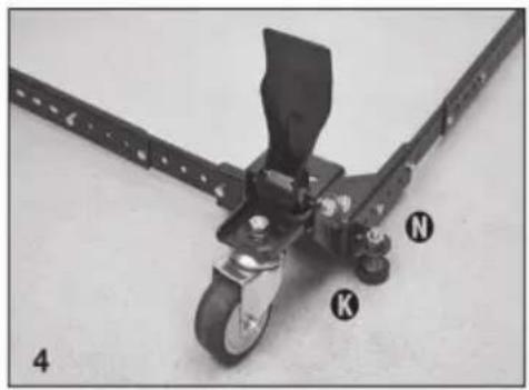
Close-up of a hand using a tool to adjust or install a mechanical component, no visible text or symbols- Insert rubber glide foot "K" into the threaded hole on the side of the corner. Spin M10 nut "N" onto the top of the rubber glide foot.
- Repeat steps 1 through 4 on the Front Left corner "A".
- Attach 3" wheel "J" to Rear Right corner "F".
a. Insert extra bolt into the axle hole from the inside of the corner. Insert the bolt into the wheel housing just far enough to act as a "hanger" for the nylon wheel bushing "⑧". - Carefully align 3" wheel "J", and insert M6-55 bolt "S" through hole in the outer edge of wheel housing, through wheel "J", through nylon bushing "R".
- Secure the axle bolt using using M6 flange nut "P".
- Repeat steps 6-8 for back-left corner "E", assembly is now complete!
a. Test mobility without machine. b. Add machine and secure it to the mobile base. - Lift your machine or item to be mobilized into place.
CAUTION: Check stability in both the up and down positions before using. Failure to follow safety and assembly instructions may result in personal injury or damage to product.
natural_image
Mechanical device with labeled parts K, N, and a scale-like structure (no readable text or symbols beyond labels)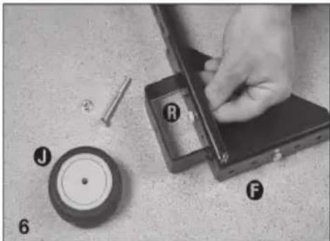
natural_image
Close-up of a hand using a tool to adjust components on a workbench, with labeled parts (J, R, F) and a circular component nearby (no readable text or symbols beyond labels)
natural_image
Close-up of hands using a wrench to adjust a mechanical component (no visible text or symbols)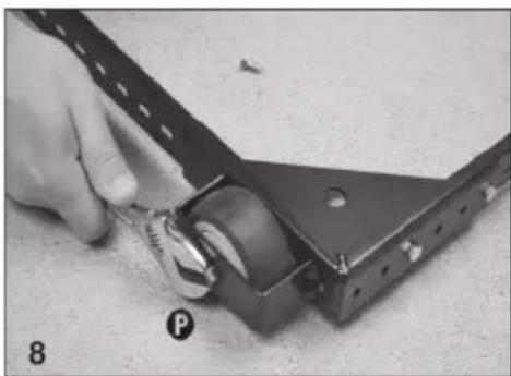
natural_image
Close-up of a hand using a tool to adjust or install a mechanical component, no visible text or symbols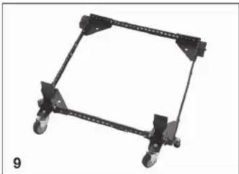
natural_image
Mechanical frame structure with four wheels and mounting brackets (no text or symbols)MAINTENANCE
- Avoid prolonged exposure to the sun to avoid aging.
- Inspect accessories for wear, cracks, and other damage before use and replace defective accessories immediately.
Manufacturer: Shanghaimuxinmuyeyouxiangongsi
Address: Shuangchenglu 803nong11hao1602A-1609shi, baoshanqu, shanghai 200000 CN.
Imported to AUS: SIHAO PTY LTD, 1 ROKEVA STREETEASTWOOD NS 2122 Australia
Imported to USA: Sanven Technology Ltd., Suite 250, 9166 Anaheim Pla Rancho Cucamonga, CA 91730
| EC | REP |
E-CrossStu GmbH
Mainzer Landstr.69, 60329 Frankfurt am Ma
| UK | REP |
YH CONSULTING LIMITED.
C/O YH Consulting Limited Office 147, Centurion H London Road, Staines-upon-Thames, Surrey, TW18 4
VEVOR®
TOUGH TOOLS, HALF PRICE
Technical Support and E-Warranty Certificate www.vevor.com/support
VEVOR®
TOUGH TOOLS, HALF PRICE
natural_image
Mechanical frame with black and silver wheels, no visible text or symbols| Liste des pièces | |||||
| S/N | Description | Qté | S/N | Description | Qté |
| COIN AVANT GAUCHE 1 | RONDELLE DE BLOCAGE M10 | 2 | |||
| COIN AVANT DROIT 1 | RONDELLE DE BLOCAGE M8 | 4 | |||
| RAIL LATÉRAL court | 4 | ÉCROU M10 | 4 | ||
| RAIL LATÉRAL Lon9 | 4 | ÉCROU M8 | 4 | ||
| COIN ARRIÈRE GAUCHE 1 | ÉCROU À BRIDE M6 | 26 | |||
| COIN ARRIÈRE DROIT 1 | BOULON HEXAGONAL M6-12 | 24 | |||
| LEVIER AU PIED | 2 | DOUILLE DE ROUE EN NYLON | 2 | ||
| PLAQUE PIVOTANTE | 2 | BOULON D'AXE M6-55 | 2 | ||
| ROULETTES PIVOTANTES DE 3" | 2 | BOULON DE CHARIOT M8-85 | 4 | ||
| ROUE 3" | 2 | DOUILLE DE LEVIER DE PIED EN NYLON | 4 | ||
| PIED DE GLISSEMENT EN CAOUTCHOUC 2 | |||||
Assembly Examples
Be sure to follow Safety and Assembly Instructions. Keep in mind the actual operation of your machine and the effect it has on overall stability.

A long, narrow base, such as on a jointer, would benefit from this arrangement. Most machines may be arranged to the convenience of the user.

A short, narrow base, such as found on a drill press or bandsaw, may benefit from this arrangement. Due to swivel rotation, base may sit out of level. Rotate swivel wheel away from base to correct.
- Select and arrange the Corners and the Side Rails as necessary to assemble the base to your machine's footprint. Position Side Rails into corners as far as is practical.
a. Below is a standard arrangement, but many different arrangements are possible. You can use 1, 2, or 3 rails on either side.
b. To expand the functionality of this mobile base on larger machine's, purchase additional rails online at http://www.boratool.com/rail-kit-w-hardware-pm1000-htc2000
- Bolt the Side Rails to the corners and each other using these simple rules:
a. All connections require the use of (2) M6-12 bolts and (2) M6 nuts at each end of the connections
Note: Insert bolts so that the nuts are on the INSIDE of the mobile base.
- Re-check dimensions with the tape measure, then tighten all bolts and nuts. If you are building a square configuration the measurements between diagonal corners should be relatively close.

natural_image
Mechanical bracket assembly with four metal parts, no visible text or symbols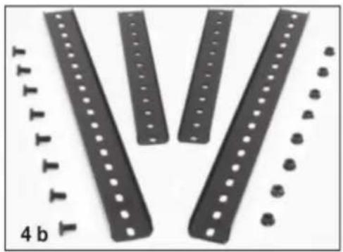
natural_image
Close-up of four black metal bars with holes and a row of small circular indentations, labeled '4 b' (no text or symbols on the bars themselves)
natural_image
Mechanical bracket component with mounting holes and mounting points (no text or symbols visible)Attaching Wheels and Casters
-
Attach swivel plate "H" to the Front Right corner "B" using M8-85 carriage bolt "T", M8 lock washer "M", and M8 nut "O".
-
Attach foot lever "G" to the Front Right corner "B".
a. Slide the M8-85 carriage bolt "⑦" through the hole on the inside of the corner, hang a nylon foot lever bushing "⑩" on the end of the bolt. Insert an extra bolt into the hole from the outside of the corner just far enough to act as a "hanger" for the other nylon bushing.
b. Carefully slide the foot lever into place between the nylon bushings.
c. Push the carriage bolt through the foot lever, nylon washers, and opposite side of the corner. Secure it using the M8 lock washer "M".
- Attach swivel caster "①" to swivel plate "②" using M10 lock washer "③" and M10 nut "④".

natural_image
Mechanical assembly with labeled parts (G, T, B, U) and part number 2 a, no readable text or symbols beyond labels
natural_image
Close-up of hands using a tool to adjust or install a metal mechanical component (no visible text or symbols)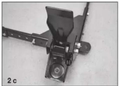
natural_image
Mechanical component with black bracket and mounting bracket, labeled '2 c' (no readable text or symbols)
natural_image
Close-up of a hand using a pliers to adjust a mechanical component (no visible text or symbols)- Insert rubber glide foot "K" into the threaded hole on the side of the corner. Spin M10 nut "N" onto the top of the rubber glide foot.
- Repeat steps 1 through 4 on the Front Left corner "A".
- Attach 3" wheel "J" to Rear Right corner "F".
a. Insert extra bolt into the axle hole from the inside of the corner. Insert the bolt into the wheel housing just far enough to act as a "hanger" for the nylon wheel bushing "R".
- Carefully align 3" wheel "J", and insert M6-55 bolt "S" through hole in the outer edge of wheel housing, through wheel "J", through nylon bushing "R".
- Secure the axle bolt using using M6 flange nut "P".
- Repeat steps 6-8 for back-left corner "E", assembly is now complete!
a. Test mobility without machine.
b. Add machine and secure it to the mobile base.
- Lift your machine or item to be mobilized into place.
CAUTION: Check stability in both the up and down positions before using. Failure to follow safety and assembly instructions may result in personal injury or damage to product.

natural_image
Mechanical device with labeled parts K, N, and a black lever mechanism (no text or symbols beyond labels)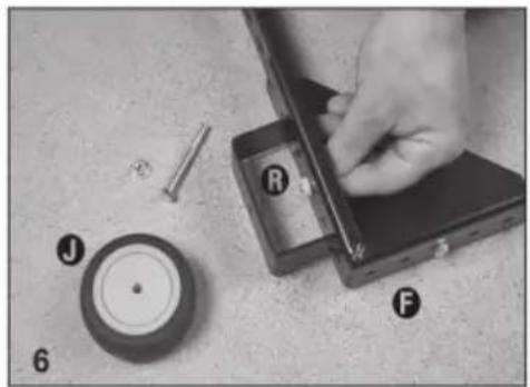
natural_image
Close-up of a hand using a tool to adjust components on a workbench, with labeled parts J, F, and R (no readable text or symbols beyond labels)
natural_image
Close-up of hands using a wrench to adjust a mechanical component (no text or symbols visible)
natural_image
Close-up of a hand using a tool to adjust or install a mechanical component, no visible text or symbols
natural_image
Mechanical frame with four wheels and a rectangular frame, no text or symbols visibleENTRETIEN
C/O YH Consulting Limited Bureau 147, Centurion House, London Road, Staines-upon-Thames, Surrey, TW18 4AX
VEVOR®
TOUGH TOOLS, HALF PRICE
www.vevor.com/support
MOBILE BASIS
MODELL: GZB88093
natural_image
Mechanical frame with black and silver wheels, no visible text or symbolsFoto als Referenz
Be sure to follow Safety and Assembly Instructions. Keep in mind the actual operation of your machine and the effect it has on overall stability.

A long, narrow base, such as on a jointer, would benefit from this arrangement. Most machines may be arranged to the convenience of the user.

A short, narrow base, such as found on a drill press or bandsaw, may benefit from this arrangement. Due to swivel rotation, base may sit out of level. Rotate swivel wheel away from base to correct.
- Select and arrange the Corners and the Side Rails as necessary to assemble the base to your machine's footprint. Position Side Rails into corners as far as is practical.
a. Below is a standard arrangement, but many different arrangements are possible. You can use 1, 2, or 3 rails on either side.
b. To expand the functionality of this mobile base on larger machine's, purchase additional rails online at http://www.boratool.com/rail-kit-w-hardware-pm1000-htc2000
- Bolt the Side Rails to the corners and each other using these simple rules:
a. All connections require the use of (2) M6-12 bolts and (2) M6 nuts at each end of the connections
Note: Insert bolts so that the nuts are on the INSIDE of the mobile base.
- Re-check dimensions with the tape measure, then tighten all bolts and nuts. If you are building a square configuration the measurements between diagonal corners should be relatively close.
natural_image
Mechanical bracket assembly with four metal parts and mounting brackets, labeled '4 a' (no text or symbols on the components themselves)
natural_image
Close-up of four black metal bars with holes and a row of small circular indentations, labeled '4 b' (no text or symbols on the bars themselves)
natural_image
Mechanical bracket component with mounting holes and mounting points (no text or symbols visible)Attaching Wheels and Casters
-
Attach swivel plate “H” to the Front Right corner “B” using M8-85 carriage bolt “T”, M8 lock washer “M”, and M8 nut “O”.
-
Attach foot lever "G" to the Front Right corner "B".
a. Slide the M8-85 carriage bolt "⑦" through the hole on the inside of the corner, hang a nylon foot lever bushing "⑩" on the end of the bolt. Insert an extra bolt into the hole from the outside of the corner just far enough to act as a "hanger" for the other nylon bushing.
b. Carefully slide the foot lever into place between the nylon bushings.
c. Push the carriage bolt through the foot lever, nylon washers, and opposite side of the corner. Secure it using the M8 lock washer "M".
- Attach swivel caster "①" to swivel plate "②" using M10 lock washer "③" and M10 nut "④".

natural_image
Mechanical assembly with labeled parts (G, T, B, U) and part number 2 a, no readable text or symbols beyond labels
natural_image
Close-up of hands using a tool to adjust or install a metal mechanical component (no visible text or symbols)
natural_image
Mechanical component with black frame and mounting bracket, labeled '2 c' (no readable text or symbols)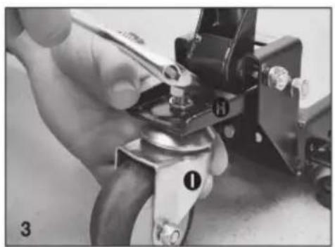
natural_image
Close-up of a hand using a pliers to adjust a mechanical component (no visible text or symbols)- Insert rubber glide foot "K" into the threaded hole on the side of the corner. Spin M10 nut "N" onto the top of the rubber glide foot.
- Repeat steps 1 through 4 on the Front Left corner "A".
- Attach 3" wheel "J" to Rear Right corner "F".
a. Insert extra bolt into the axle hole from the inside of the corner. Insert the bolt into the wheel housing just far enough to act as a "hanger" for the nylon wheel bushing "R".
- Carefully align 3" wheel "J", and insert M6-55 bolt "S" through hole in the outer edge of wheel housing, through wheel "J", through nylon bushing "R".
- Secure the axle bolt using using M6 flange nut "P".
- Repeat steps 6-8 for back-left corner "E", assembly is now complete!
a. Test mobility without machine.
b. Add machine and secure it to the mobile base.
- Lift your machine or item to be mobilized into place.
CAUTION: Check stability in both the up and down positions before using. Failure to follow safety and assembly instructions may result in personal injury or damage to product.
natural_image
Mechanical device with labeled parts K, N, and a black lever mechanism (no text or symbols beyond labels)
natural_image
Close-up of a hand using a tool to adjust components on a workbench, with labeled parts J, F, and R (no text or symbols beyond labels)
natural_image
Close-up of hands using a wrench to adjust a mechanical component (no text or symbols visible)
natural_image
Close-up of a hand using a tool to adjust or install a mechanical component, no visible text or symbols
natural_image
Mechanical frame with four wheels and a rectangular frame, no text or symbols visibleWARTUNG
C/O YH Consulting Limited Office 147, Centurion House, London Road, Staines-upon-Thames, Surrey, TW18 4AX
VEVOR®
TOUGH TOOLS, HALF PRICE
www.vevor.com/support
VEVOR®
TOUGH TOOLS, HALF PRICE
elettronica www.vevor.com/support
BASE MOBILE
MODELLO: GZB88093
natural_image
Mechanical frame with black and silver wheels, no visible text or symbols| Elenco delle parti | |||||
| S/N | Descrizione | Qtà | S/N | Descrizione | Qtà |
| ÿ ANGOLO ANTERIORE SINISTRO 1 | ÿ | RONDELLA DI SICUREZZA M10 | 2 | ||
| ÿ ANGOLO ANTERIORE DESTRO 1 | ÿ | RONDELLA DI SICUREZZA M8 | 4 | ||
| ÿ GUIDA LATERALE corta | 4ÿ | DADO M10 | 4 | ||
| ÿ SPONDA LATERALE Lon9 | 4ÿ | DADO M8 | 4 | ||
| ÿ ANGOLO POSTERIORE SINISTRO | 1ÿ | DADO FLANGIATO M6 | 26 | ||
| ÿ ANGOLO POSTERIORE DESTRO 1 | ÿ | BULLONE ESAGONALE M6-12 | 24 | ||
| ÿ | LEVA A PIEDE | 2ÿ | BOCCOLA RUOTA IN NYLON | 2 | |
| ÿ PIASTRA GIREVOLE | 2ÿ | BULLONE ASSE M6-55 | 2 | ||
| ÿ RUOTA GIREVOLE DA 3 " | 2ÿ | BULLONE DI TRASPORTO M8-85 | 4 | ||
| ÿ | RUOTA DA 3". | 2ÿ | BOCCOLA PEDALE LEVA IN NYLON 4 | ||
| ÿ PIEDINO SCORREVOLE IN GOMMA 2 | |||||
Assembly Examples
Be sure to follow Safety and Assembly Instructions. Keep in mind the actual operation of your machine and the effect it has on overall stability.

A long, narrow base, such as on a jointer, would benefit from this arrangement. Most machines may be arranged to the convenience of the user.

A short, narrow base, such as found on a drill press or bandsaw, may benefit from this arrangement. Due to swivel rotation, base may sit out of level. Rotate swivel wheel away from base to correct.
- Select and arrange the Corners and the Side Rails as necessary to assemble the base to your machine's footprint. Position Side Rails into corners as far as is practical.
a. Below is a standard arrangement, but many different arrangements are possible. You can use 1, 2, or 3 rails on either side.
b. To expand the functionality of this mobile base on larger machine's, purchase additional rails online at http://www.boratool.com/rail-kit-w-hardware-pm1000-htc2000
- Bolt the Side Rails to the corners and each other using these simple rules:
a. All connections require the use of (2) M6-12 bolts and (2) M6 nuts at each end of the connections
Note: Insert bolts so that the nuts are on the INSIDE of the mobile base.
- Re-check dimensions with the tape measure, then tighten all bolts and nuts. If you are building a square configuration the measurements between diagonal corners should be relatively close.

natural_image
Mechanical bracket assembly with four metal parts and mounting brackets, labeled '4 a' (no text or symbols on the components themselves)
natural_image
Close-up of four black plastic bars with circular holes and a row of small circular indentations, labeled '4 b' (no text or symbols on the bars themselves)
natural_image
Mechanical bracket component with mounting holes and mounting points (no text or symbols visible)Attaching Wheels and Casters
-
Attach swivel plate “H” to the Front Right corner “B” using M8-85 carriage bolt “T”, M8 lock washer “M”, and M8 nut “O”.
-
Attach foot lever "G" to the Front Right corner "B".
a. Slide the M8-85 carriage bolt "⑦" through the hole on the inside of the corner, hang a nylon foot lever bushing "⑩" on the end of the bolt. Insert an extra bolt into the hole from the outside of the corner just far enough to act as a "hanger" for the other nylon bushing.
b. Carefully slide the foot lever into place between the nylon bushings.
c. Push the carriage bolt through the foot lever, nylon washers, and opposite side of the corner. Secure it using the M8 lock washer "M".
- Attach swivel caster "①" to swivel plate "②" using M10 lock washer "③" and M10 nut "④".


natural_image
Mechanical assembly with labeled parts (G, T, B, U) and part number 2 a, no readable text or symbols beyond labels
natural_image
Close-up of hands using a tool to adjust or install a metal mechanical component (no visible text or symbols)
natural_image
Mechanical component with black bracket and mounting bracket, labeled '2 c' (no readable text or symbols)
natural_image
Close-up of a hand using a pliers to adjust a mechanical component (no visible text or symbols)- Insert rubber glide foot "K" into the threaded hole on the side of the corner. Spin M10 nut "N" onto the top of the rubber glide foot.
- Repeat steps 1 through 4 on the Front Left corner "A".
- Attach 3" wheel "J" to Rear Right corner "F".
a. Insert extra bolt into the axle hole from the inside of the corner. Insert the bolt into the wheel housing just far enough to act as a "hanger" for the nylon wheel bushing "R".
- Carefully align 3" wheel "J", and insert M6-55 bolt "S" through hole in the outer edge of wheel housing, through wheel "J", through nylon bushing "R".
- Secure the axle bolt using using M6 flange nut "P".
- Repeat steps 6-8 for back-left corner "E", assembly is now complete!
a. Test mobility without machine.
b. Add machine and secure it to the mobile base.
- Lift your machine or item to be mobilized into place.
CAUTION: Check stability in both the up and down positions before using. Failure to follow safety and assembly instructions may result in personal injury or damage to product.

natural_image
Mechanical device with labeled parts K, N, and a black lever mechanism (no text or symbols beyond labels)
natural_image
Close-up of a hand using a tool to adjust components on a workbench, with labeled parts J, R, F and a circular component (no readable text or symbols beyond labels)
natural_image
Close-up of hands using a wrench to adjust a mechanical component (no text or symbols visible)
natural_image
Close-up of a hand using a tool to adjust or install a mechanical component, no visible text or symbols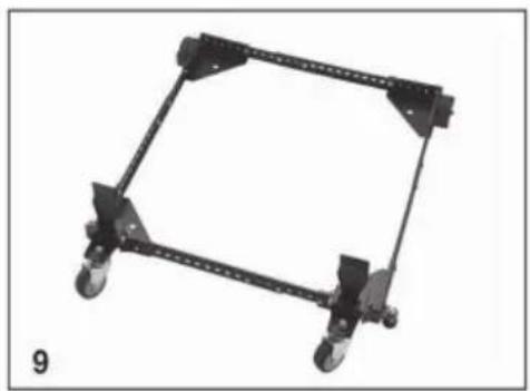
natural_image
Mechanical frame with four wheels and a rectangular frame, no text or symbols visibleMANUTENZIONE
Importato in AUS: SIHAO PTY LTD, 1 ROKEVA STREETEASTWOOD NSW 2122 Australia
C/O YH Consulting Limited Ufficio 147, Centurion House, London Road, Staines-upon-Thames, Surrey, TW18 4AX
VEVOR®
TOUGH TOOLS, HALF PRICE
natural_image
Mechanical frame with black and silver wheels, no visible text or symbolsBe sure to follow Safety and Assembly Instructions. Keep in mind the actual operation of your machine and the effect it has on overall stability.

A long, narrow base, such as on a jointer, would benefit from this arrangement. Most machines may be arranged to the convenience of the user.

A short, narrow base, such as found on a drill press or bandsaw, may benefit from this arrangement. Due to swivel rotation, base may sit out of level. Rotate swivel wheel away from base to correct.
- Select and arrange the Corners and the Side Rails as necessary to assemble the base to your machine's footprint. Position Side Rails into corners as far as is practical.
a. Below is a standard arrangement, but many different arrangements are possible. You can use 1, 2, or 3 rails on either side.
b. To expand the functionality of this mobile base on larger machine's, purchase additional rails online at http://www.boratool.com/rail-kit-w-hardware-pm1000-htc2000
- Bolt the Side Rails to the corners and each other using these simple rules:
a. All connections require the use of (2) M6-12 bolts and (2) M6 nuts at each end of the connections
Note: Insert bolts so that the nuts are on the INSIDE of the mobile base.
- Re-check dimensions with the tape measure, then tighten all bolts and nuts. If you are building a square configuration the measurements between diagonal corners should be relatively close.

natural_image
Mechanical bracket assembly with four metal parts and mounting brackets, labeled '4 a' (no text or symbols on the components themselves)
natural_image
Close-up of four black metal bars with holes and a row of small circular indentations, labeled '4 b' (no text or symbols on the bars themselves)
natural_image
Mechanical bracket component with mounting holes and mounting points (no text or symbols visible)Attaching Wheels and Casters
-
Attach swivel plate "H" to the Front Right corner "B" using M8-85 carriage bolt "T", M8 lock washer "M", and M8 nut "O".
-
Attach foot lever "G" to the Front Right corner "B".
a. Slide the M8-85 carriage bolt "⑦" through the hole on the inside of the corner, hang a nylon foot lever bushing "⑩" on the end of the bolt. Insert an extra bolt into the hole from the outside of the corner just far enough to act as a "hanger" for the other nylon bushing.
b. Carefully slide the foot lever into place between the nylon bushings.
c. Push the carriage bolt through the foot lever, nylon washers, and opposite side of the corner. Secure it using the M8 lock washer "M".
- Attach swivel caster "①" to swivel plate "②" using M10 lock washer "③" and M10 nut "④".


natural_image
Mechanical assembly with labeled parts (G, T, B, U) and part number 2 a, no readable text or symbols beyond labels
natural_image
Close-up of hands using a tool to adjust or install a metal mechanical component (no visible text or symbols)
natural_image
Mechanical component with black bracket and mounting bracket, labeled '2 c' (no readable text or symbols)
natural_image
Close-up of a hand using a pliers to adjust a mechanical component (no visible text or symbols)- Insert rubber glide foot "K" into the threaded hole on the side of the corner. Spin M10 nut "N" onto the top of the rubber glide foot.
- Repeat steps 1 through 4 on the Front Left corner "A".
- Attach 3" wheel "J" to Rear Right corner "F".
a. Insert extra bolt into the axle hole from the inside of the corner. Insert the bolt into the wheel housing just far enough to act as a "hanger" for the nylon wheel bushing "R".
- Carefully align 3" wheel "J", and insert M6-55 bolt "S" through hole in the outer edge of wheel housing, through wheel "J", through nylon bushing "R".
- Secure the axle bolt using using M6 flange nut "P".
- Repeat steps 6-8 for back-left corner "E", assembly is now complete!
a. Test mobility without machine.
b. Add machine and secure it to the mobile base.
- Lift your machine or item to be mobilized into place.
CAUTION: Check stability in both the up and down positions before using. Failure to follow safety and assembly instructions may result in personal injury or damage to product.

natural_image
Mechanical device with labeled parts K, N, and a black lever mechanism (no text or symbols beyond labels)
natural_image
Close-up of a hand using a tool to adjust components on a workbench, with labeled parts J, F, and R (no readable text or symbols beyond labels)
natural_image
Close-up of hands using a wrench to adjust a mechanical component (no text or symbols visible)
natural_image
Close-up of a hand using a tool to adjust or install a mechanical component, no visible text or symbols
natural_image
Mechanical frame with four wheels and a rectangular frame, no text or symbols visibleMANTENIMIENTO
Importado a AUS: SIHAO PTY LTD, 1 ROKEVA STREETEASTWOOD NSW 2122 Australia
Importado a EE. UU.: Sanven Technology Ltd., Suite 250, 9166 Anaheim Place, Rancho Cucamonga, CA 91730

E-CrossStu GmbH
C/O YH Consulting Limited Oficina 147, Centurion House, London Road, Staines upon Thames, Surrey, TW18 4AX
VEVOR®
TOUGH TOOLS, HALF PRICE
www.vevor.com/support
VEVOR®
TOUGH TOOLS, HALF PRICE
natural_image
Mechanical frame with black and silver wheels, no visible text or symbols| Lista części | |||||
| S/N | Opis | Ilość | S/N | Opis | Ilość |
| LEWY PRZÓD NAROŻNIK 1 | PODKŁADKA BLOKUJĄCA M10 | 2 | |||
| PRAWY PRZEDNI NAROŻNIK 1 | PODKŁADKA BLOKUJĄCA M8 | 4 | |||
| Krótka BELKA BOCZNA | 4 | NAKRĘTKA M10 | 4 | ||
| PROWADNICA BOCZNA Lon9 | 4 | NAKRĘTKA M8 | 4 | ||
| TYLNY LEWY NAROŻNIK 1 | NAKRĘTKA KOŁNIERZOWA M6 | 26 | |||
| TYLNY PRAWY NAROŻNIK 1 | ŚRUBA SZEŚCIOKĄTNA M6-12 | 24 | |||
| DŻWIGNIA NOŻNA | 2 | NYLO | NOWA TULEJA KOŁA | 2 | |
| PŁYTA OBROTOWA | 2 | ŚRUBA OSI M6-55 | 2 | ||
| 3-CALOWE KÓŁKO OBROTOWE | 2 | ŚRUBA PODSTAWOWA M8-85 | 4 | ||
| 3-calowe KOŁO | 2 | NYLO | NOWA TULEJA DŻWIGNI NOŻNEJ 4 | ||
| GUMOWA STOPKA ŚLIZGOWA 2 | |||||
Assembly Examples
Be sure to follow Safety and Assembly Instructions. Keep in mind the actual operation of your machine and the effect it has on overall stability.
A long, narrow base, such as on a jointer, would benefit from this arrangement. Most machines may be arranged to the convenience of the user.
A short, narrow base, such as found on a drill press or bandsaw, may benefit from this arrangement. Due to swivel rotation, base may sit out of level. Rotate swivel wheel away from base to correct.
- Select and arrange the Corners and the Side Rails as necessary to assemble the base to your machine's footprint. Position Side Rails into corners as far as is practical.
a. Below is a standard arrangement, but many different arrangements are possible. You can use 1, 2, or 3 rails on either side.
b. To expand the functionality of this mobile base on larger machine's, purchase additional rails online at http://www.boratool.com/rail-kit-w-hardware-pm1000-htc2000
- Bolt the Side Rails to the corners and each other using these simple rules:
a. All connections require the use of (2) M6-12 bolts and (2) M6 nuts at each end of the connections
Note: Insert bolts so that the nuts are on the INSIDE of the mobile base.
- Re-check dimensions with the tape measure, then tighten all bolts and nuts. If you are building a square configuration the measurements between diagonal corners should be relatively close.

natural_image
Mechanical bracket assembly with four metal parts and mounting brackets, labeled '4 a' (no text or symbols on the components themselves)
natural_image
Close-up of four black metal bars with holes and a row of small circular indentations, labeled '4 b' (no text or symbols on the bars themselves)
natural_image
Mechanical bracket component with mounting holes and mounting points (no text or symbols visible)Attaching Wheels and Casters
-
Attach swivel plate "H" to the Front Right corner "B" using M8-85 carriage bolt "T", M8 lock washer "M", and M8 nut "O".
-
Attach foot lever "G" to the Front Right corner "B".
a. Slide the M8-85 carriage bolt "⑦" through the hole on the inside of the corner, hang a nylon foot lever bushing "⑩" on the end of the bolt. Insert an extra bolt into the hole from the outside of the corner just far enough to act as a "hanger" for the other nylon bushing.
b. Carefully slide the foot lever into place between the nylon bushings.
c. Push the carriage bolt through the foot lever, nylon washers, and opposite side of the corner. Secure it using the M8 lock washer "M".
- Attach swivel caster "①" to swivel plate "②" using M10 lock washer "③" and M10 nut "④".


natural_image
Mechanical assembly with labeled parts (G, T, B, U) and part number 2 a, no readable text or symbols beyond labels
natural_image
Close-up of hands using a tool to adjust or install a metal mechanical component (no visible text or symbols)
natural_image
Mechanical component with black bracket and mounting bracket, labeled '2 c' (no readable text or symbols)
natural_image
Close-up of a hand using a pliers to adjust a mechanical component (no visible text or symbols)- Insert rubber glide foot "K" into the threaded hole on the side of the corner. Spin M10 nut "N" onto the top of the rubber glide foot.
- Repeat steps 1 through 4 on the Front Left corner "A".
- Attach 3" wheel "J" to Rear Right corner "F".
a. Insert extra bolt into the axle hole from the inside of the corner. Insert the bolt into the wheel housing just far enough to act as a "hanger" for the nylon wheel bushing "R".
- Carefully align 3" wheel "J", and insert M6-55 bolt "S" through hole in the outer edge of wheel housing, through wheel "J", through nylon bushing "R".
- Secure the axle bolt using using M6 flange nut "P".
- Repeat steps 6-8 for back-left corner "E", assembly is now complete!
a. Test mobility without machine.
b. Add machine and secure it to the mobile base.
- Lift your machine or item to be mobilized into place.
CAUTION: Check stability in both the up and down positions before using. Failure to follow safety and assembly instructions may result in personal injury or damage to product.

natural_image
Mechanical device with labeled parts K, N, and a black lever mechanism (no text or symbols beyond labels)
natural_image
Close-up of a hand using a tool to adjust components on a workbench, with labeled parts J, F, and R (no readable text or symbols beyond labels)
natural_image
Close-up of hands using a wrench to adjust a mechanical component (no text or symbols visible)
natural_image
Close-up of a hand using a tool to adjust or install a mechanical component, no visible text or symbols
natural_image
Mechanical frame with four wheels and a rectangular frame (no text or symbols visible)KONSERWACJA
Import do AUS: SIHAO PTY LTD, 1 ROKEVA STREETEASTWOOD NSW 2122 Australii
Import do USA: Sanven Technology Ltd., Suite 250, 9166 Anaheim Place, Rancho Cucamonga, CA 91730
| REPREZENT KE |
E-CrossStu GmbH
Mainzer Landstr.69, 60329 Frankfurt nad Menem.
C/O YH Consulting Limited Office 147, Centurion House, London Road, Staines-upon-Thames, Surrey, TW18 4AX
VEVOR®
TOUGH TOOLS, HALF PRICE
www.vevor.com/support
MOBIELE BASIS
MODEL: GZB88093
natural_image
Mechanical frame with black and silver wheels, no visible text or symbolsFoto ter referentie
HULP NODIG? NEEM CONTACT MET ONS OP!
| Onderdelenlijst | |||||
| S/N | Beschrijving | Aantal S/N | Beschrijving | Aantal | |
| ÿ VOOR LINKER HOEK 1ÿ | M10 BORGRING | 2 | |||
| ÿ RECHTER VOORHOEK 1ÿ | M8 BORGRING | 4 | |||
| ÿ Korte ZIJREK | 4ÿ | M10 MOER | 4 | ||
| ÿ Lon9 ZIJREK | 4ÿ | M8 MOER | 4 | ||
| ÿ ACHTER LINKER HOEK 1ÿ | M6 FLENSMOER | 26 | |||
| ÿ RECHTER ACHTER HOEK 1 | ÿ | M6-12 ZESKANTIGE BOUT | 24 | ||
| ÿ | VOET HENDEL | 2ÿ | NYLON WIELBUS | 2 | |
| ÿ DRAAIPLAAT | 2ÿ | M6-55 ASBOUT | 2 | ||
| ÿ 3" | ZWENKWIEL | 2ÿ | M8-85 DRAAGBOUT | 4 | |
| ÿ | 3" WIEL | 2ÿ | NYLON VOETHENDELBUS 4 | ||
| ÿ RUBBEREN GLIJVOET 2 | |||||
Assembly Examples
Be sure to follow Safety and Assembly Instructions. Keep in mind the actual operation of your machine and the effect it has on overall stability.

A long, narrow base, such as on a jointer, would benefit from this arrangement. Most machines may be arranged to the convenience of the user.

A short, narrow base, such as found on a drill press or bandsaw, may benefit from this arrangement. Due to swivel rotation, base may sit out of level. Rotate swivel wheel away from base to correct.
- Select and arrange the Corners and the Side Rails as necessary to assemble the base to your machine's footprint. Position Side Rails into corners as far as is practical.
a. Below is a standard arrangement, but many different arrangements are possible. You can use 1, 2, or 3 rails on either side.
b. To expand the functionality of this mobile base on larger machine's, purchase additional rails online at http://www.boratool.com/rail-kit-w-hardware-pm1000-htc2000
- Bolt the Side Rails to the corners and each other using these simple rules:
a. All connections require the use of (2) M6-12 bolts and (2) M6 nuts at each end of the connections
Note: Insert bolts so that the nuts are on the INSIDE of the mobile base.
- Re-check dimensions with the tape measure, then tighten all bolts and nuts. If you are building a square configuration the measurements between diagonal corners should be relatively close.

natural_image
Mechanical bracket assembly with four metal parts and mounting brackets, labeled '4 a' (no text or symbols on the components themselves)
natural_image
Close-up of four black metal bars with holes and a row of small circular indentations, labeled '4 b' (no text or symbols on the bars themselves)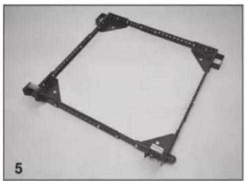
natural_image
Mechanical bracket component with mounting holes and mounting points (no text or symbols visible)Attaching Wheels and Casters
-
Attach swivel plate “H” to the Front Right corner “B” using M8-85 carriage bolt “T”, M8 lock washer “M”, and M8 nut “O”.
-
Attach foot lever "G" to the Front Right corner "B".
a. Slide the M8-85 carriage bolt "⑦" through the hole on the inside of the corner, hang a nylon foot lever bushing "⑩" on the end of the bolt. Insert an extra bolt into the hole from the outside of the corner just far enough to act as a "hanger" for the other nylon bushing.
b. Carefully slide the foot lever into place between the nylon bushings.
c. Push the carriage bolt through the foot lever, nylon washers, and opposite side of the corner. Secure it using the M8 lock washer "M".
- Attach swivel caster "①" to swivel plate "②" using M10 lock washer "③" and M10 nut "④".


natural_image
Mechanical assembly with labeled parts (G, T, B, U) and part number 2 a, no readable text or symbols beyond labels
natural_image
Close-up of hands using a tool to adjust or install a metal mechanical component (no visible text or symbols)
natural_image
Mechanical component with black bracket and mounting bracket, labeled '2 c' (no readable text or symbols)
natural_image
Close-up of a hand using a pliers to adjust a mechanical component (no visible text or symbols)- Insert rubber glide foot "K" into the threaded hole on the side of the corner. Spin M10 nut "N" onto the top of the rubber glide foot.
- Repeat steps 1 through 4 on the Front Left corner "A".
- Attach 3" wheel "J" to Rear Right corner "F".
a. Insert extra bolt into the axle hole from the inside of the corner. Insert the bolt into the wheel housing just far enough to act as a "hanger" for the nylon wheel bushing "R".
- Carefully align 3" wheel "J", and insert M6-55 bolt "S" through hole in the outer edge of wheel housing, through wheel "J", through nylon bushing "R".
- Secure the axle bolt using using M6 flange nut "P".
- Repeat steps 6-8 for back-left corner "E", assembly is now complete!
a. Test mobility without machine.
b. Add machine and secure it to the mobile base.
- Lift your machine or item to be mobilized into place.
CAUTION: Check stability in both the up and down positions before using. Failure to follow safety and assembly instructions may result in personal injury or damage to product.

natural_image
Mechanical device with labeled parts K, N, and a black lever mechanism (no text or symbols beyond labels)
natural_image
Close-up of a hand using a tool to adjust components on a workbench, with labeled parts J, F, and R (no readable text or symbols beyond labels)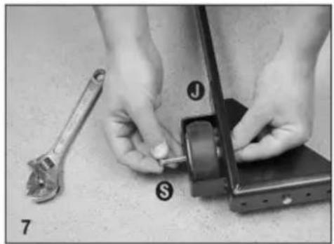
natural_image
Close-up of hands using a wrench to adjust a mechanical component (no text or symbols visible)
natural_image
Close-up of a hand using a tool to adjust or install a mechanical component, no visible text or symbols
natural_image
Mechanical frame with four wheels and a rectangular frame, no text or symbols visibleONDERHOUD
C/O YH Consulting Limited Kantoor 147, Centurion House, London Road, Staines-upon-Thames, Surrey, TW18 4AX
VEVOR®
TOUGH TOOLS, HALF PRICE
Technische ondersteuning en e-garantiecertificaat www.vevor.com/support
VEVOR®
TOUGH TOOLS, HALF PRICE
www.vevor.com/support
MOBIL BAS
MODELL: GZB88093
natural_image
Mechanical frame with black and silver wheels, no visible text or symbolsFoto för referens
BEHÖVER HJÄLP? KONTAKTA OSS!
| Delarlista | |||||
| S/N | Beskrivning | Antal | S/N | Beskrivning | Antal |
| ÿ FRAMVÄNSTER HÖRN 1 ÿ | M10 LÅSBRICKA | 2 | |||
| ÿ FRAMRE HÖGER HÖRN 1 ÿ | M8 LÅSBRICKA | 4 | |||
| ÿ Kort SIDORÄNNE | 4 ÿ | M10 MUTTER | 4 | ||
| ÿ Lon9 SIDORÄN | 4 ÿ | M8 MUTTER | 4 | ||
| ÿ BAKRE VÄNSTER HÖRN 1 ÿ | M6 FLÄNSMUTTER | 26 | |||
| ÿ BAK HÖGER HÖRN 1 ÿ | M6-12 HEXBOLTEN | 24 | |||
| ÿ | FOTSPAK | 2 ÿ | NYLON | HJULBUSSNING | 2 |
| ÿ VÄNDPLÅTA | 2 ÿ | M6-55 AXELBOLT | 2 | ||
| ÿ 3" SVÄNGLIG HJUL | 2 ÿ | M8-85 BORDBULT | 4 | ||
| ÿ | 3" HJUL | 2 ÿ | NYLON | FOTSPAKSBUSNING 4 | |
| ÿ GUMMI GLIDFOT 2 | |||||
Assembly Examples
Be sure to follow Safety and Assembly Instructions. Keep in mind the actual operation of your machine and the effect it has on overall stability.

A long, narrow base, such as on a jointer, would benefit from this arrangement. Most machines may be arranged to the convenience of the user.

A short, narrow base, such as found on a drill press or bandsaw, may benefit from this arrangement. Due to swivel rotation, base may sit out of level. Rotate swivel wheel away from base to correct.
- Select and arrange the Corners and the Side Rails as necessary to assemble the base to your machine's footprint. Position Side Rails into corners as far as is practical.
a. Below is a standard arrangement, but many different arrangements are possible. You can use 1, 2, or 3 rails on either side.
b. To expand the functionality of this mobile base on larger machine's, purchase additional rails online at http://www.boratool.com/rail-kit-w-hardware-pm1000-htc2000
- Bolt the Side Rails to the corners and each other using these simple rules:
a. All connections require the use of (2) M6-12 bolts and (2) M6 nuts at each end of the connections
Note: Insert bolts so that the nuts are on the INSIDE of the mobile base.
- Re-check dimensions with the tape measure, then tighten all bolts and nuts. If you are building a square configuration the measurements between diagonal corners should be relatively close.

natural_image
Mechanical bracket assembly with four metal parts, no visible text or symbols
natural_image
Close-up of four black plastic bars with circular holes and a row of small circular indentations, labeled '4 b' (no text or symbols on the bars themselves)
natural_image
Mechanical bracket component with mounting holes and mounting points (no text or symbols visible)Attaching Wheels and Casters
-
Attach swivel plate “H” to the Front Right corner “B” using M8-85 carriage bolt “T”, M8 lock washer “M”, and M8 nut “O”.
-
Attach foot lever "G" to the Front Right corner "B".
a. Slide the M8-85 carriage bolt "⑦" through the hole on the inside of the corner, hang a nylon foot lever bushing "⑩" on the end of the bolt. Insert an extra bolt into the hole from the outside of the corner just far enough to act as a "hanger" for the other nylon bushing.
b. Carefully slide the foot lever into place between the nylon bushings.
c. Push the carriage bolt through the foot lever, nylon washers, and opposite side of the corner. Secure it using the M8 lock washer "M".
- Attach swivel caster "①" to swivel plate "②" using M10 lock washer "③" and M10 nut "④".


natural_image
Mechanical assembly with labeled parts (G, T, B, U) and part number 2 a, no readable text or symbols beyond labels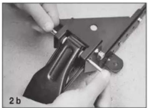
natural_image
Close-up of hands using a tool to adjust or install a metal mechanical component (no visible text or symbols)
natural_image
Mechanical component with black bracket and mounting bracket, labeled '2 c' (no readable text or symbols)
natural_image
Close-up of a hand using a pliers to adjust a mechanical component (no visible text or symbols)- Insert rubber glide foot "K" into the threaded hole on the side of the corner. Spin M10 nut "N" onto the top of the rubber glide foot.
- Repeat steps 1 through 4 on the Front Left corner "A".
- Attach 3" wheel "J" to Rear Right corner "F".
a. Insert extra bolt into the axle hole from the inside of the corner. Insert the bolt into the wheel housing just far enough to act as a "hanger" for the nylon wheel bushing "R".
- Carefully align 3" wheel "J", and insert M6-55 bolt "S" through hole in the outer edge of wheel housing, through wheel "J", through nylon bushing "R".
- Secure the axle bolt using using M6 flange nut "P".
- Repeat steps 6-8 for back-left corner "E", assembly is now complete!
a. Test mobility without machine.
b. Add machine and secure it to the mobile base.
- Lift your machine or item to be mobilized into place.
CAUTION: Check stability in both the up and down positions before using. Failure to follow safety and assembly instructions may result in personal injury or damage to product.

natural_image
Mechanical device with labeled parts K, N, and a black lever mechanism (no text or symbols beyond labels)
natural_image
Close-up of a hand using a tool to adjust components on a workbench, with labeled parts J, F, and R (no readable text or symbols beyond labels)
natural_image
Close-up of hands using a wrench to adjust a mechanical component (no text or symbols visible)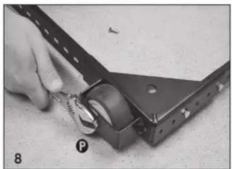
natural_image
Close-up of a hand using a tool to adjust or install a mechanical component, no visible text or symbols
natural_image
Mechanical frame with four wheels and a rectangular frame, no text or symbols visibleUNDERHÅLL
C/O YH Consulting Limited Office 147, Centurion House, London Road, Staines-upon-Thames, Surrey, TW18 4AX
VEVOR®
TOUGH TOOLS, HALF PRICE
www.vevor.com/support