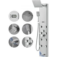
8039FL - Shower panel Vevor - Free user manual and instructions

Find the device manual for free 8039FL Vevor in PDF.

Vevor 8039FL - Shower panel
📄 160 pages English EN Download 💬 AI Question 11 questions ⚙️ Specs
Notice Vevor 8039FL - page 1
Pick your language and provide your email: we'll send you a specifically translated version.
Product Type Shower Panel
Brand Vevor
Model 8039FL
Power Supply Hydroelectric (AC 6V)
Temperature Display Yes, digital
LED Light Yes
Number of Modes 6 modes
Hand Shower 3 settings
Bathtub Spout Yes
Finish Brushed Nickel, fingerprint-resistant
Material Stainless Steel, Brass, PVC, ABS
Connection G1/2" (standard thread)
Mounting Wall-mounted, by bracket fixation
Approximate Height 1200 mm
Approximate Width 200 mm
Approximate Depth 30 mm
Approximate Weight 5 kg
Warranty Electronic warranty certificate available at www.vevor.com/support

Frequently Asked Questions - 8039FL Vevor

How to install the Vevor 8039FL shower panel?
Measure the desired installation height, mark the wall at the positions of the suspension brackets (top and bottom). Fix the brackets to the wall with the provided self-tapping screws. Connect the hot and cold water pipes (red and blue) ensuring proper orientation. Hang the panel onto the brackets until it is securely in place. Make sure it does not wobble before use.
What are the available modes on this model?
The model 8039FL offers six modes: overhead shower, hand shower (3 settings), bathtub spout, and other combinations. Refer to the manual for mode details.
How to clean and maintain the shower panel?
Regularly clean the surface with water or a mild detergent, then wipe with a soft cloth. Avoid abrasive products. For brushed nickel finishes, quick cleaning extends the product's durability.
What to do if water pressure is low?
Check that the water inlet pipes (red and blue) are not kinked or blocked. Also ensure seals are tight. If the problem persists, clean the inlet filters.
How does the temperature display work?
The digital display shows the water temperature in real time. It is powered by the hydroelectric current (AC 6V) generated by water flow. No batteries are needed for this function.
The LED light does not turn on, what to do?
Check that the hydroelectric power is active (sufficient water flow is needed). If the LED remains off, contact Vevor technical support at www.vevor.com/support.
Can I use a hand shower with this panel?
Yes, the model 8039FL comes with a hand shower with three settings and a 1.5 meter hose. It attaches to the provided wall bracket.
Is the panel compatible with an instantaneous water heater?
The standard G1/2'' connection is compatible with most installations. Ensure water pressure is between 0.5 and 5 bars for optimal operation.
How to get the warranty certificate?
The electronic warranty certificate is available at www.vevor.com/support. Have your model number and purchase date ready.
Is the panel compliant with FCC standards?
Yes, this device complies with part 15 of the FCC rules. It may cause interference, but this can be corrected by reorienting the antenna or moving the device away from the receiver.

User questions about 8039FL Vevor

1 question about this device. Answer the ones you know or ask your own.

Ask a new question about this device

Your email remains private: it is only used to notify you if someone answers your question.

How to stabilize the hot water temperature on the Vevor 8039FL shower panel?
Frequently Asked Questions - 05/07/2026
Response Notice-Facile

The Vevor 8039FL shower panel features a real-time temperature display and a dual inlet water supply system (red for hot water, blue for cold water). If the hot water does not stabilize, here are the checks to perform:

Priority Checks

  • Supply Tubes: The internal tubes (red and blue) must not be bent or curved, even slightly. During installation, ensure they remain straight behind the panel. Bending disrupts pressure and prevents proper regulation.
  • Pressure Balance: A pressure difference between hot and cold water is the most common cause. Open both supply taps (hot and cold water) equally, then gradually adjust the mixer by slowly turning the handle. It takes a few seconds for the water to stabilize in the circuit.
  • Tight Connections: The 8039FL connects with G1/2". Ensure that all joints are completely tight. A minor water leak can also create pressure instability.
  • Minimum Water Heater Flow: If your water heater is flow-activated (common models), the panel with six modes may sometimes require a variable flow. Check that your water heater can maintain a stable temperature at low flow.

Once these points are checked, the temperature display of the 8039FL will allow you to see in real-time if stabilization improves. If the problem persists, it means one of these causes has not been resolved - particularly the bending of the tubes or the pressure imbalance.

Respond (be the first)

Download the instructions for your Shower panel in PDF format for free! Find your manual 8039FL - Vevor and take your electronic device back in hand. On this page are published all the documents necessary for the use of your device. 8039FL by Vevor.

USER MANUAL 8039FL Vevor

Technical Support and E-Warranty Certificate www.vevor.com/support

SHOWER PANEL TOWER

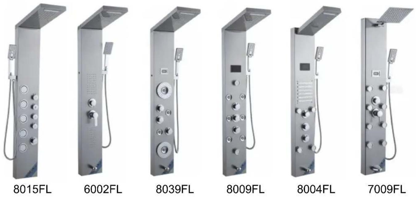
MODEL: 8015FL/6002FL/8039FL/8009FL/8004FL/7009FL

We continue to be committed to providing you with tools at competitive prices. "Save Half", "Half Price", or any other similar expressions used by us only represent an estimate of savings you might benefit from buying certain tools with us compared to top brands, and does not necessarily mean that all categories of tools offered are covered. We kindly remind you to verify carefully when placing an order with us whether you are actually saving half in comparison with the top major brands.

VEVOR®

TOUGH TOOLS, HALF PRICE

SHOWER PANEL TOWER
Vevor 8039FL - SHOWER PANEL TOWER - 1

NEED HELP? CONTACT US!

Have product questions? Need technical support? Please feel free to contact us:

Technical Support and E-Warranty Certificate www.vevor.com/support

This is the original instruction. Please read all manual instructions carefully before operating. VEVOR reserves the right to interpret the user manual. The appearance of the product shall be subject to the product you received. Please forgive us that we won't inform you if there are any technology or software updates on our product.

PRODUCT INTRODUCTION

Vevor 8039FL - PRODUCT INTRODUCTION - 1Warning-To reduce the risk of injury, user must read in manual carefully.
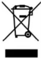
Vevor 8039FL - PRODUCT INTRODUCTION - 2CORRECT DISPOSALThis product is subject to the provision of European Di 2012/19/EC. The symbol showing a wheelie bin crossed through indicates that the product requires separate refu collection in the European Union. This applies to the p and all accessories marked with this symbol. Products r as such may not be discarded with normal domestic w must be taken to a collection point for recycling electric electronic devices.

Warning Tips:

Vevor 8039FL - Warning Tips: - 1

  1. During the installation process, it is best to wear gloves to prevent sharp corners on the panel from scratching the palm of the hand.
  2. When installing the shower, ensure that all joints are tightened to avoid water leakage.
  3. Ensure that the red and blue water inlet pipes inside the panel are in a folded state to avoid affecting water pressure.
  4. When the shower is not in use, please close the switch valve of the shower.

SAVE THESE INSTRUCTIONS

FCC Information

CAUTION: Changes or modifications not expressly approved by the party responsible for compliance could void the user's authority to operate the equipment!

This device complies with Part 15 of the FCC Rules. Operation is subject to the following two conditions:

1) This product may cause harmful interference. 2) This product must accept any interference received, including interference that may cause undesired operation.

WARNING: Changes or modifications to this product not expressly approved by the party responsible for compliance could void the user's authority to operate the product.

Note: This product has been tested and found to comply with the limits for a Class B digital device pursuant to Part 15 of the FCC Rules. These limits are designed to provide reasonable protection against harmful interference in a residential installation.

This product generates, uses and can radiate radio frequency energy, and if installed and used in accordance with the instructions, may cause harmful interference to radio communications. However, there is no guarantee that interference will not occur in a particular installation. If this product does cause harmful interference to radio or television reception, which can be determined by turning the product off and on, the user is encouraged to try to correct the interference by one or more of the following measures.

  • Reorient or relocate the receiving antenna.
  • Increase the distance between the product and the receiver.
  • Connect the product to an outlet on a circuit different from that to which the receiver is connected.
  • Consult the dealer or an experienced radio/TV technician for assistance.

INSTALLATION INSTRUCTIONS

Model8015FL6002FL8039FL8009FL8004FL7009FL
Mounting TypeWall MountWall MountWall MountWall MountWall MountWall Mount
Connection ThreadG1/2"G1/2"G1/2"G1/2"G1/2"G1/2"
FunctionsFour ModesFive ModesSix ModesSix ModesSix ModesFive Modes
Tub Spout×
Temperature Display××
LED Lamp××
Power×Dry Cell (DC3V)Dry Cell (DC3V)Hydro Power (AC6V)Hydro Power (AC6V)Dry Cell (DC3V)
Hand Shower3-Setting1-Setting3-Setting3-Setting3-Setting3-Setting
FinishFingerprint-free Brushed Nickel shower system
MaterialStainless Steel, Brass, PVC, ABS

PARTS LIST

MODEL8015FL8039FL8009FL6002FL8004FL7009FL
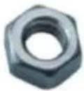
M6 nutVevor 8039FL - PARTS LIST - 14pcs4pcs0pcs0pcs
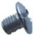
M6 * 10 screwVevor 8039FL - PARTS LIST - 24pcs4pcs0pcs0pcs
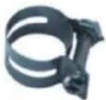
Hose ClampVevor 8039FL - PARTS LIST - 32pcs2pcs2pcs0pcs
M4 * 10 screwVevor 8039FL - PARTS LIST - 40pcs0pcs2pcs0pcs
Brass shower armVevor 8039FL - PARTS LIST - 50pcs0pcs0pcs1pcs
Single function handheld showerVevor 8039FL - PARTS LIST - 60pcs1pcs0pcs0pcs
Panel cotton bagVevor 8039FL - PARTS LIST - 71pcs1pcs1pcs1pcs
Top spray cotton bagVevor 8039FL - PARTS LIST - 81pcs1pcs1pcs0pcs
Three function handheld showerVevor 8039FL - PARTS LIST - 91pcs0pcs1pcs1pcs
1.5 meter hand spray hoseVevor 8039FL - PARTS LIST - 101pcs1pcs1pcs1pcs
Hand spray seatVevor 8039FL - PARTS LIST - 111pcs1pcs1pcs1pcs
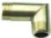
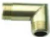
1/2 right angle adapterVevor 8039FL - PARTS LIST - 122pcs2pcs2pcs2pcs
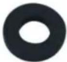
4-point rubberVevor 8039FL - PARTS LIST - 132pcs2pcs2pcs2pcs
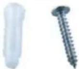
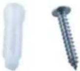
Self tapping screwVevor 8039FL - PARTS LIST - 144pcs4pcs4pcs4pcs
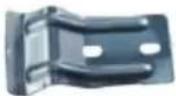
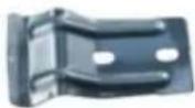
FastenerVevor 8039FL - PARTS LIST - 152pcs2pcs2pcs2pcs
GrommetVevor 8039FL - PARTS LIST - 161pcs1pcs1pcs1pcs
Hexagon nutVevor 8039FL - PARTS LIST - 171pcs1pcs1pcs1pcs

ASSEMBLY INSTRUCTIONS

MODEL 8015FL/6002FL/8039FL/8009FL
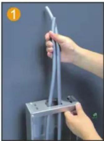
Close-up of hands installing a cable or wire component on a metal frame (no text or symbols visible).

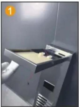
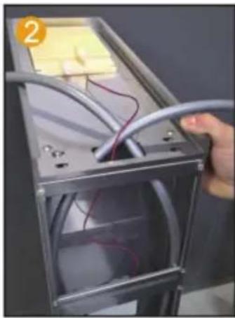
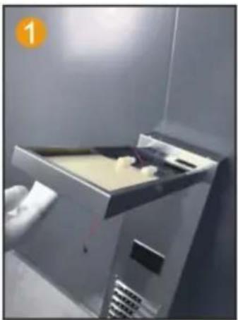
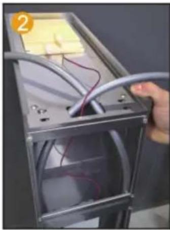
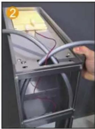
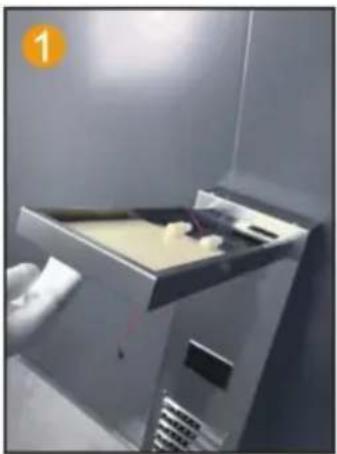
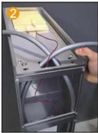
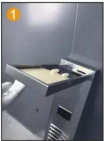
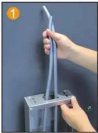
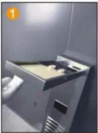
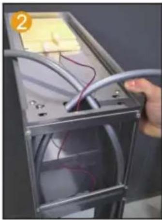
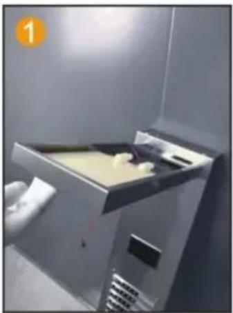
Insert the PVC pipe from the top opening to pierce out.
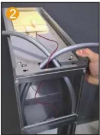
Close-up of a hand holding a metallic cable with wires inside a metal enclosure (no visible text or symbols).

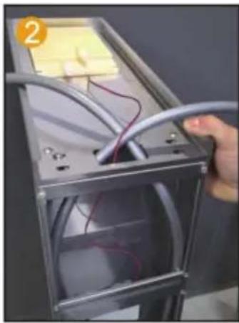
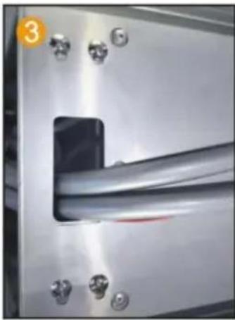
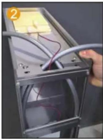
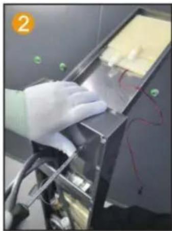
Route the LED light wire along the hole and insert it into the motherboard.
Close-up of a metallic mechanical component with a rectangular cutout and bolt holes (no visible text or symbols).

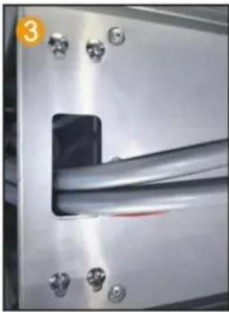
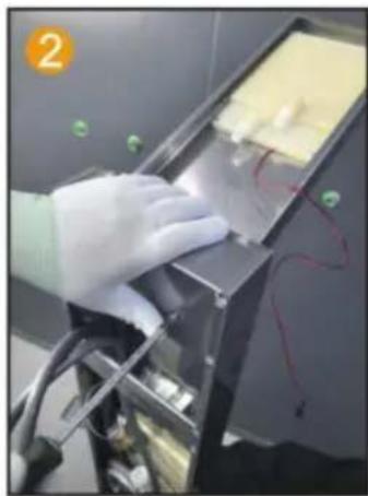
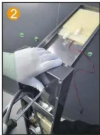
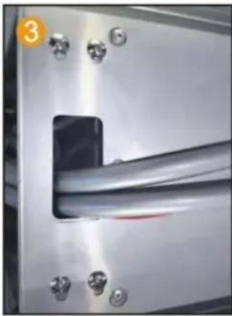
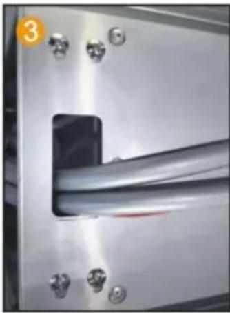
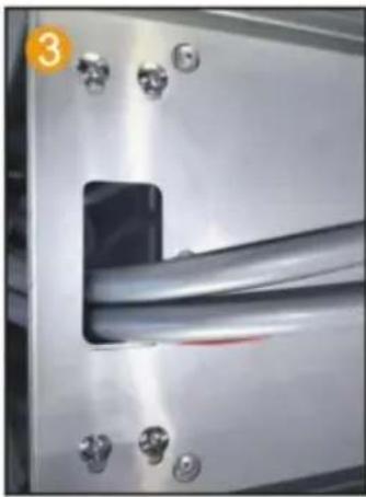
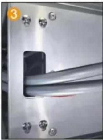
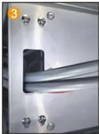
Fix the motherboard and top spray with 4 pairs of M6 screws and nuts.
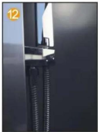
Close-up of a metallic shelf with white insulation and coiled tubing, no visible text or symbols.

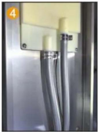
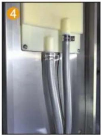
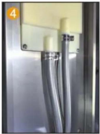
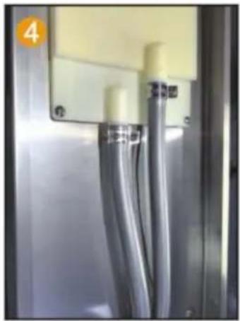
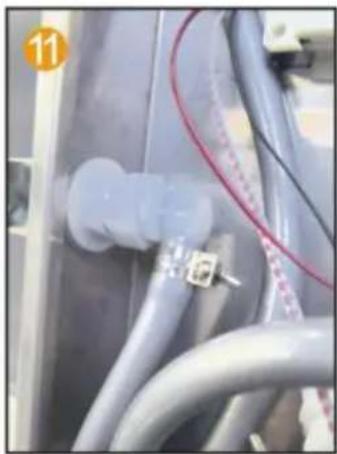
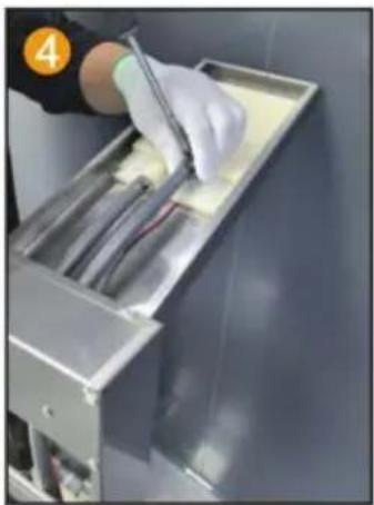
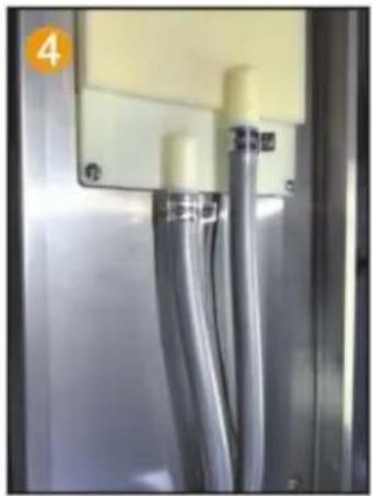
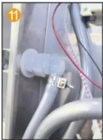
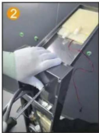
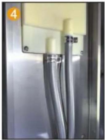
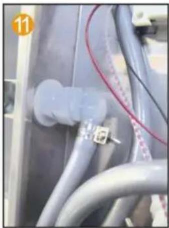
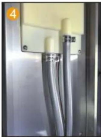
Fix the PVC pipe with a throat clamp on the top spray joint.
Close-up of hands using a tool to adjust or install a cable or wire inside an electrical enclosure (no visible text or symbols).

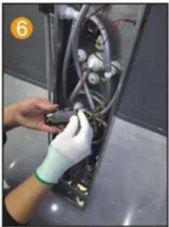
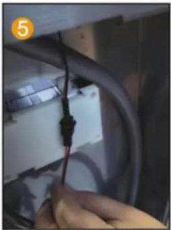
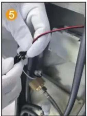
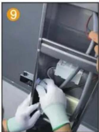
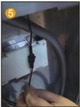
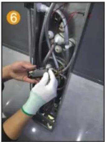
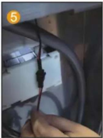
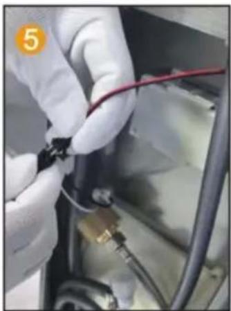
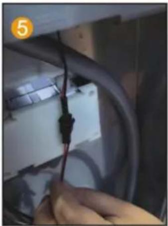
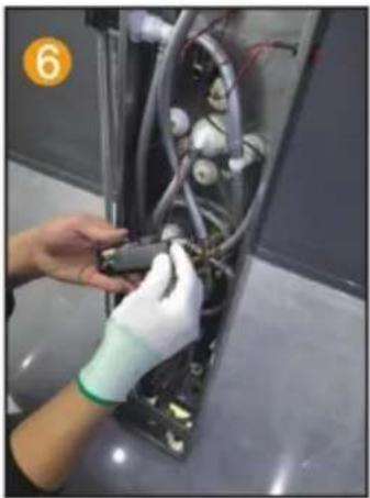
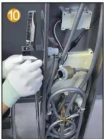
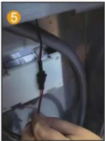
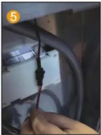
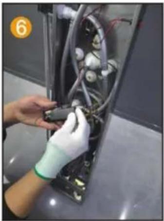
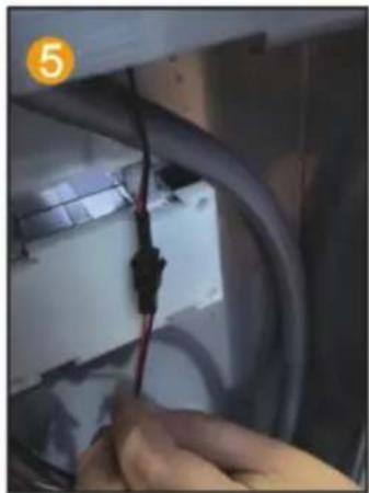
Connect the LED light cable and power supply line.
Person in gloves installing or adjusting electrical wiring inside a device (no visible text or symbols).

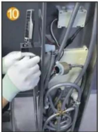
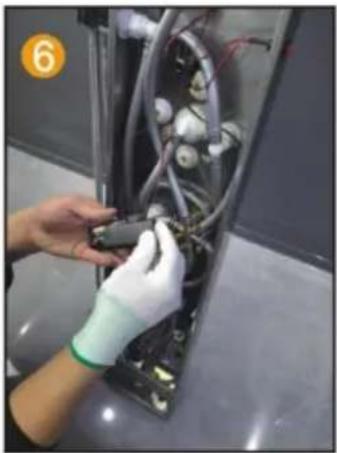
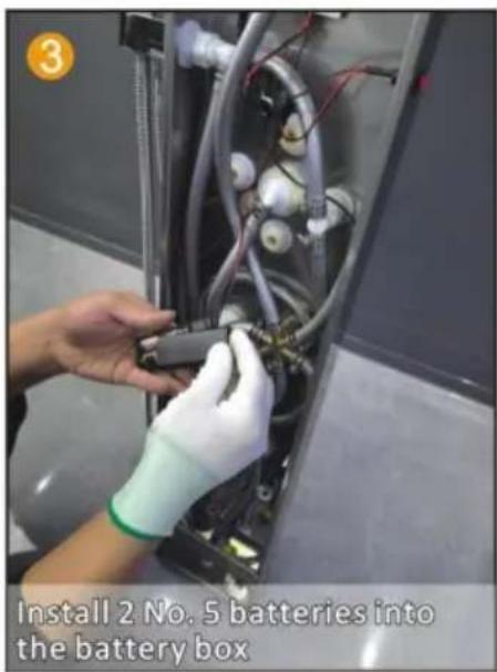
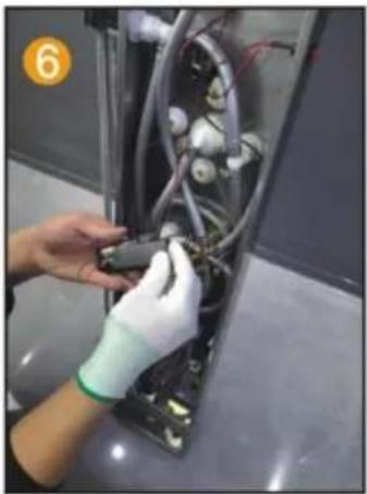
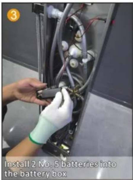
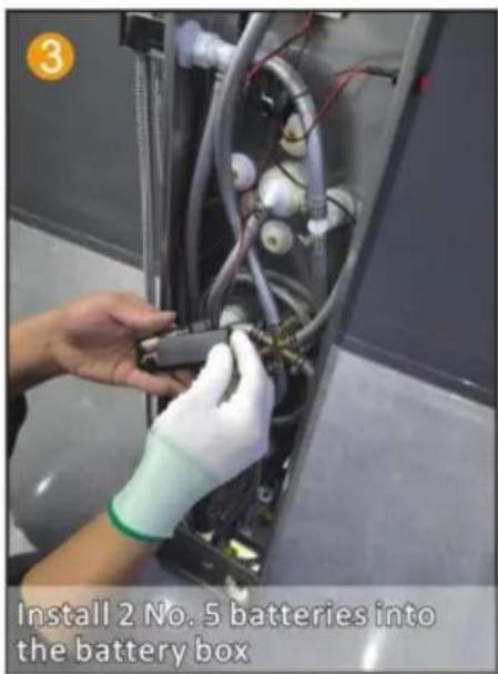
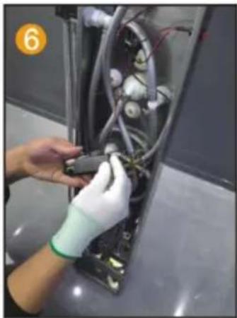
Install 2 No. 5 batteries to charge the pool box.
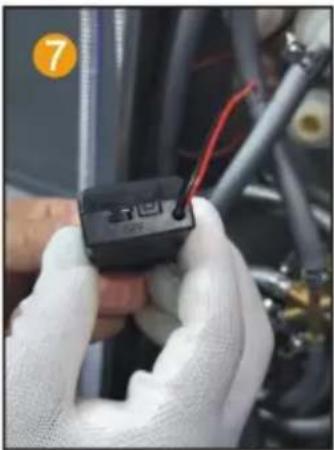
Close-up of hands holding a black electronic device with wires, next to mechanical components (no visible text or symbols).

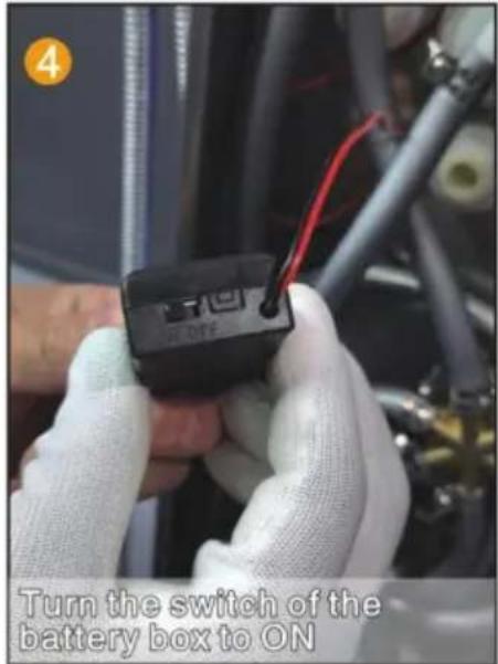
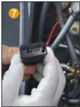
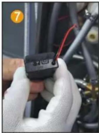
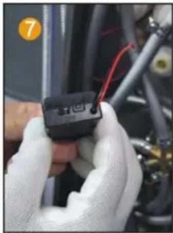
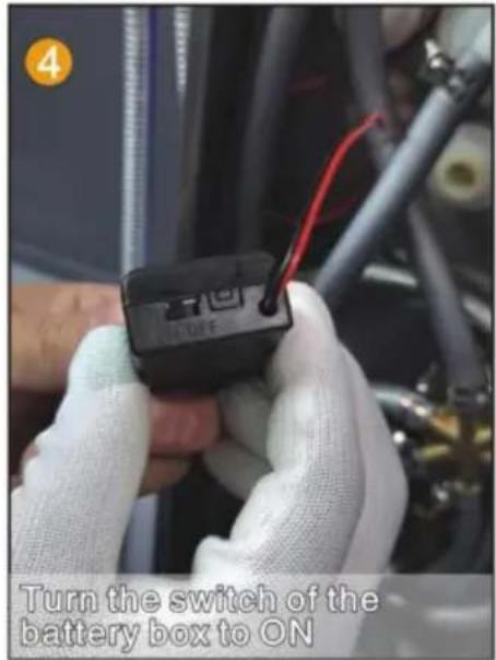
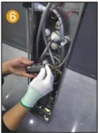
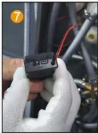
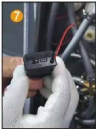
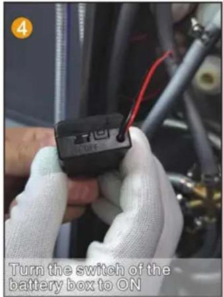
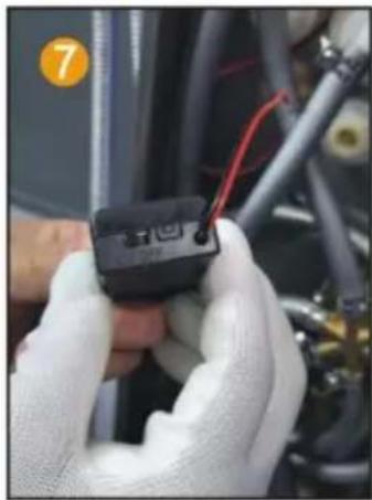
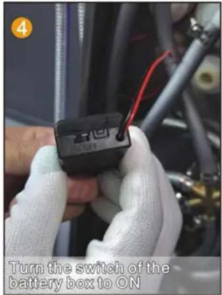
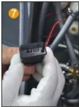
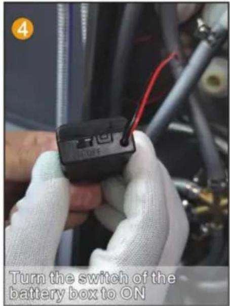
Point the switch of the battery box towards ON.
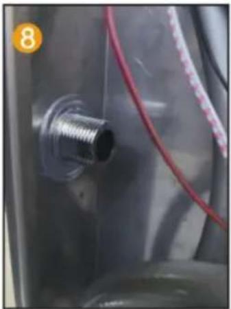
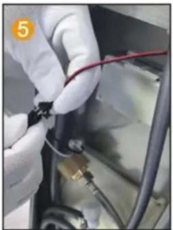
Close-up of a metallic connector with red wires attached, no visible text or symbols.

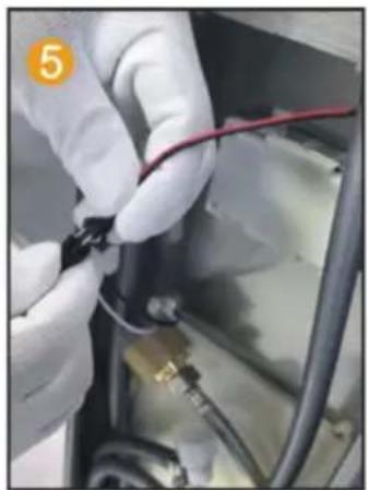
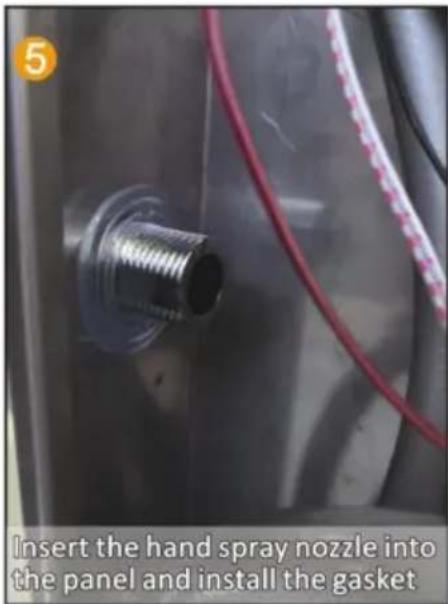
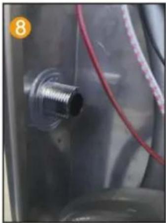
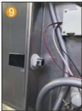
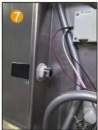
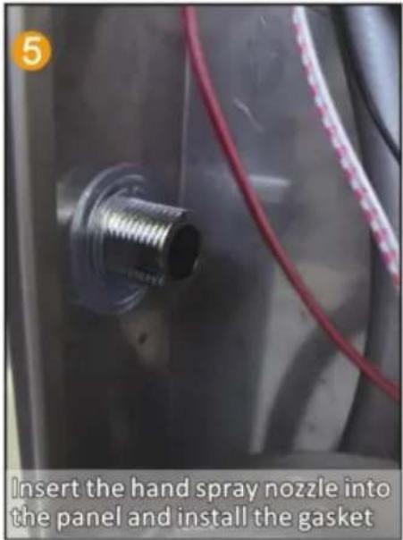
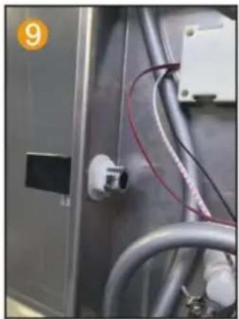
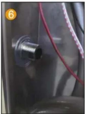
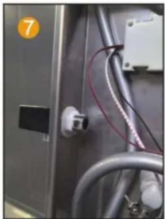
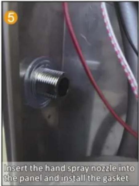
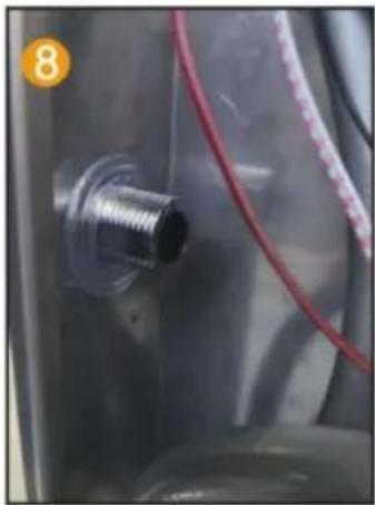
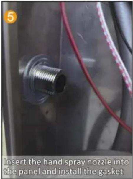
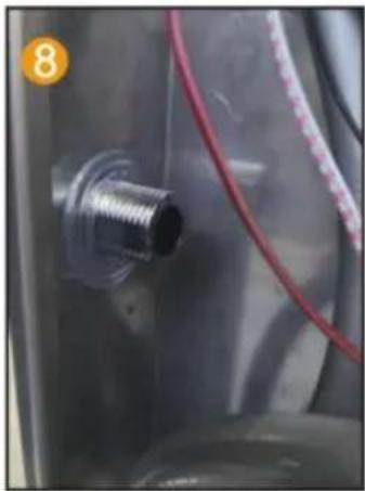
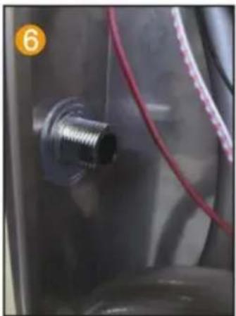
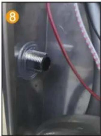
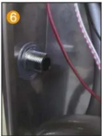
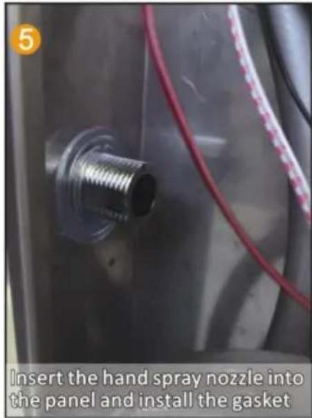
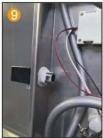
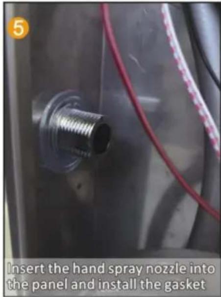
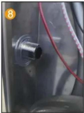
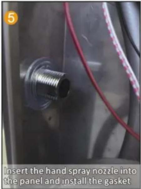
Insert the hand spray nozzle into the panel and install the gasket.
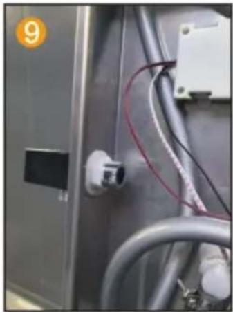
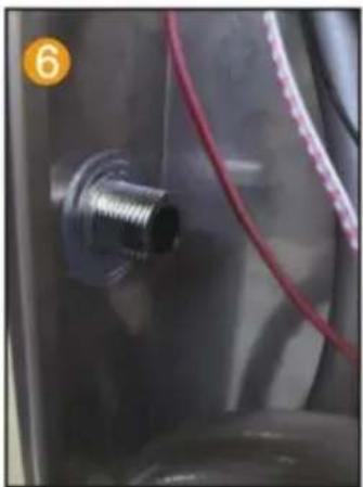
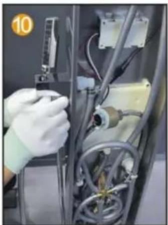
Close-up of a metallic industrial electrical panel with wiring and connectors (no visible text or symbols).

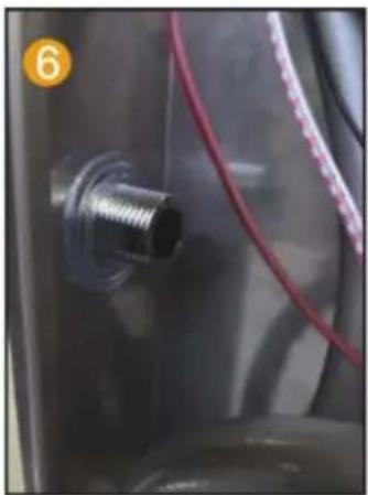
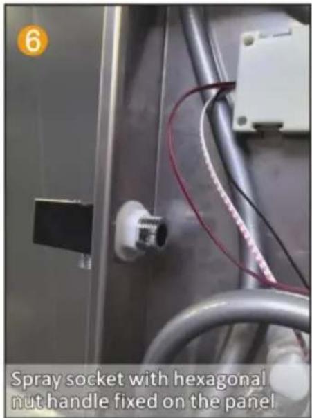
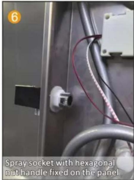
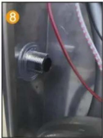
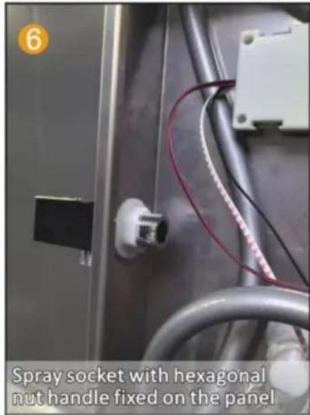
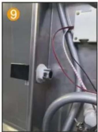
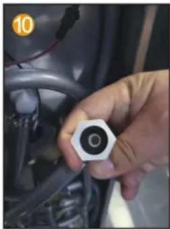
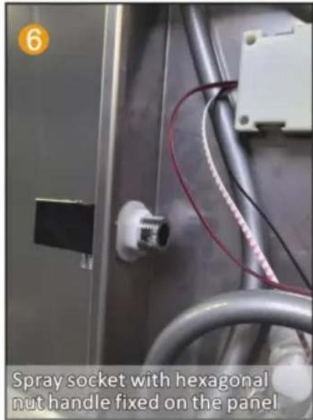
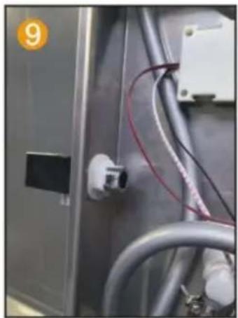
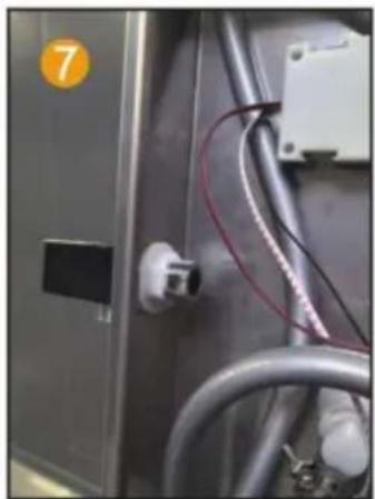
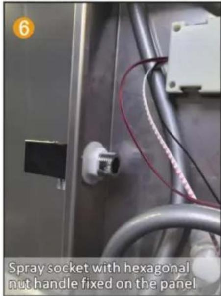
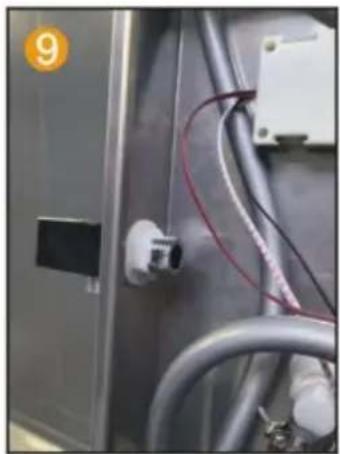
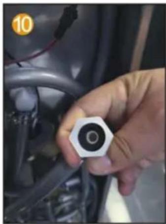
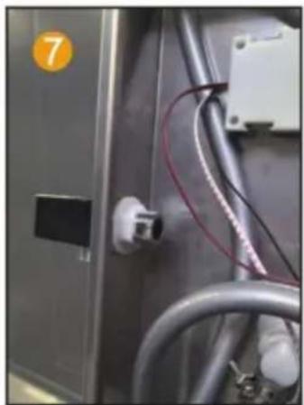
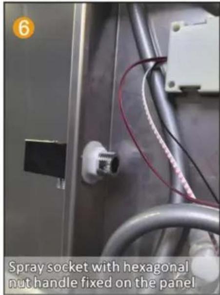
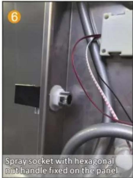
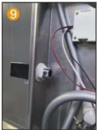
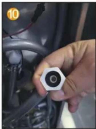
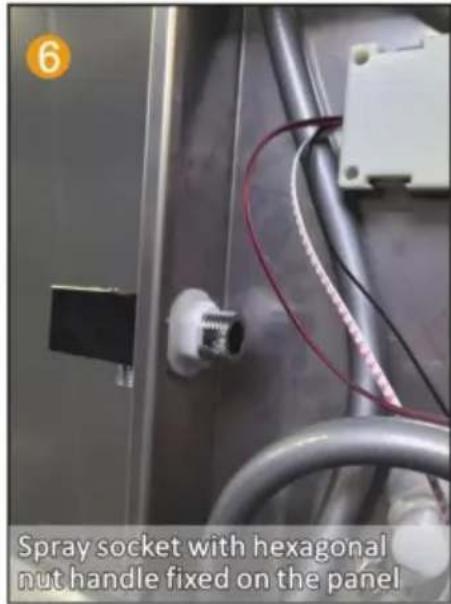
Spray socket with hexagonal nut handle fixed on the panel.

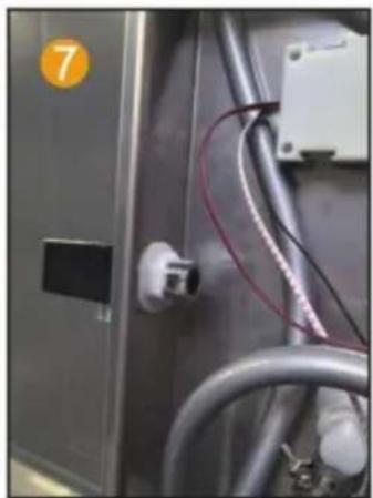
Close-up of a hand holding a small hexagonal nut component, no visible text or symbols.

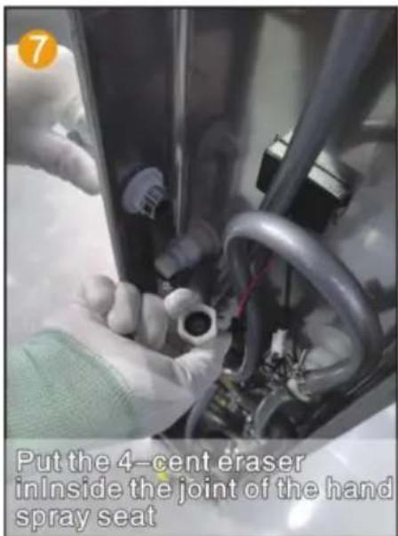
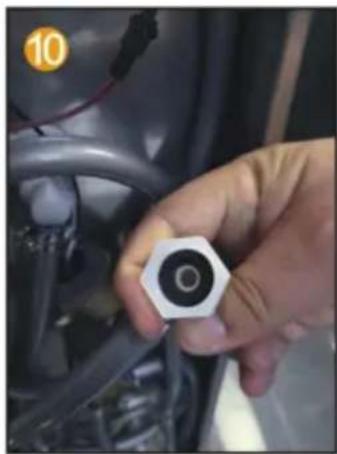
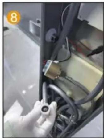
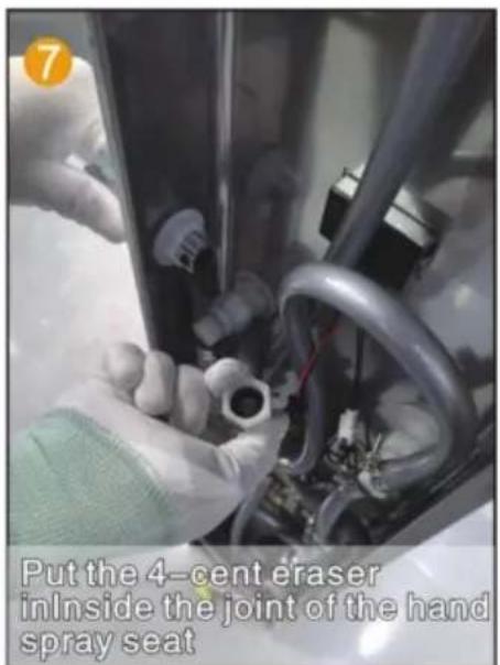
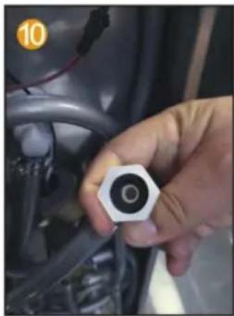
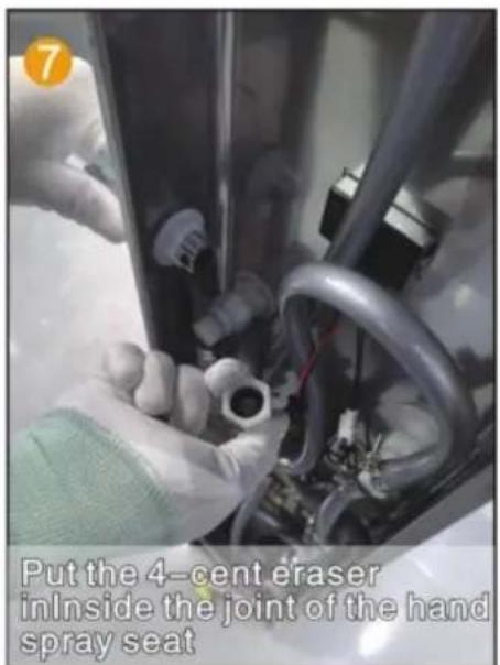
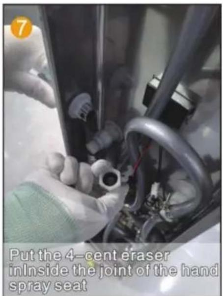
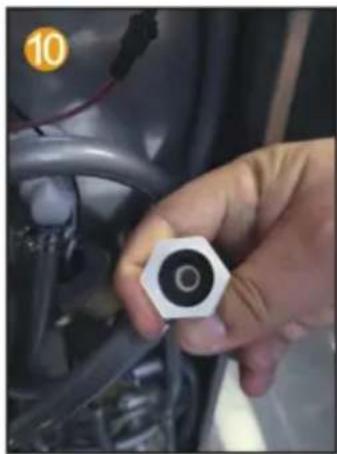
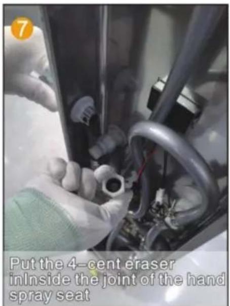
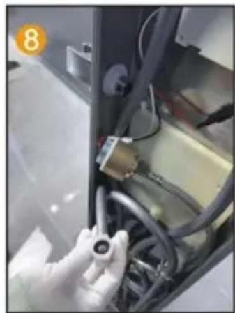
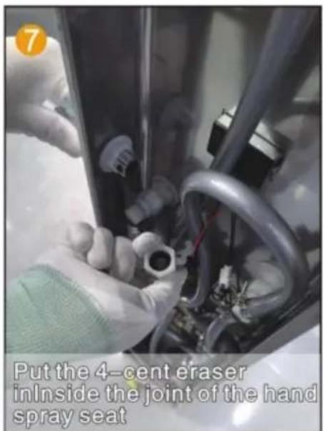
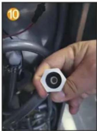
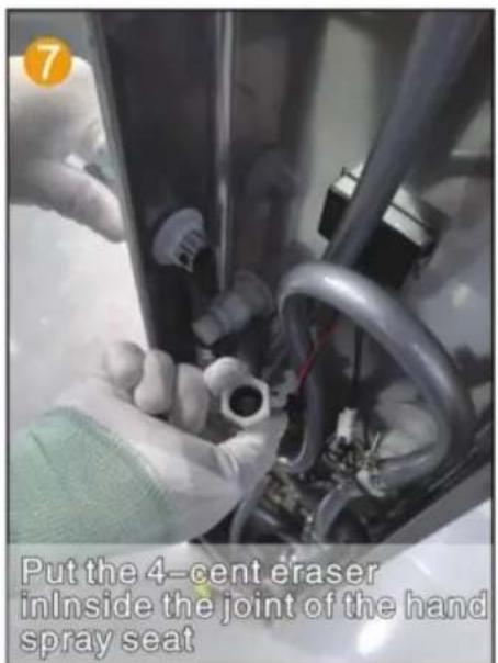
Put the 4-point rubber into the hand spray inside the joint of the seat.

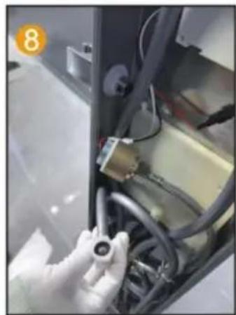
Close-up of a medical or laboratory setup with blue plastic connectors and tubing (no visible text or symbols).

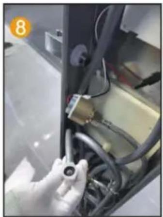
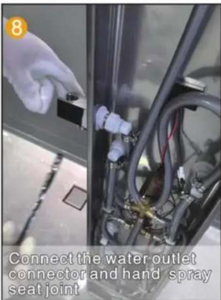
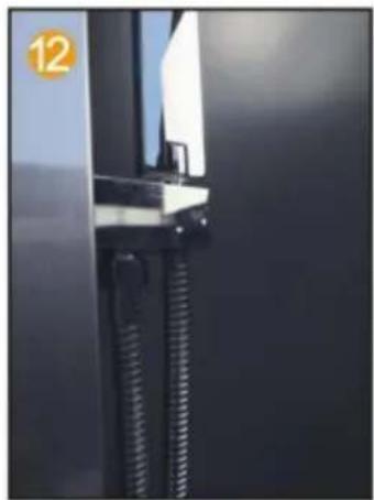
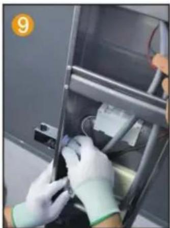
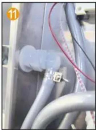
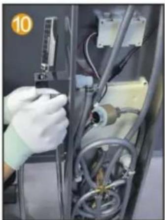
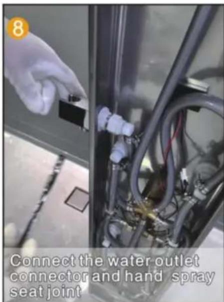
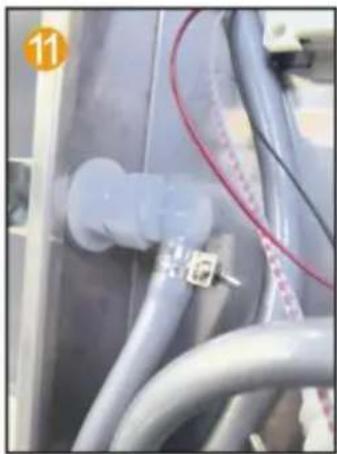
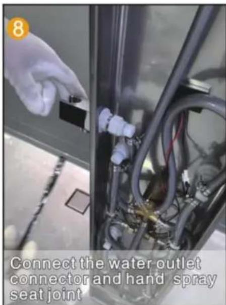
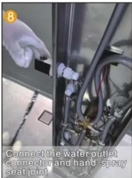
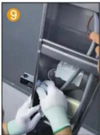
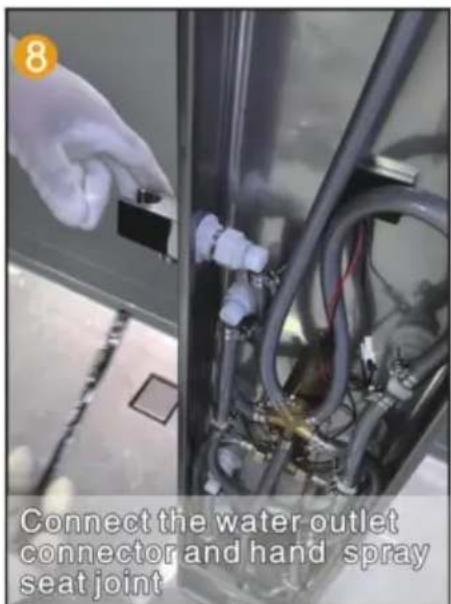
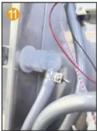
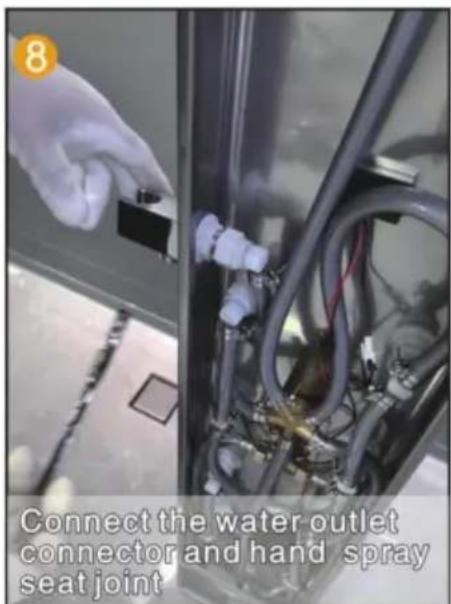
Connect the water outlet connector and hand spray seat joint.

Close-up of a mechanical component with threaded fasteners and a vertical blade (no visible text or symbols).

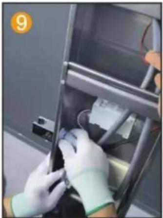
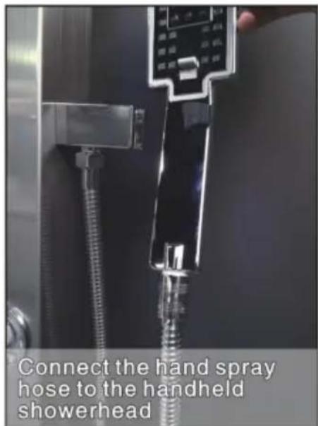
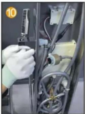
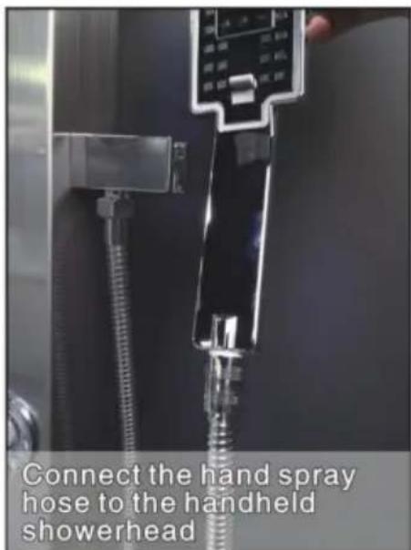
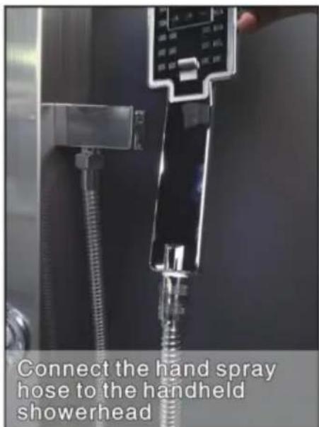
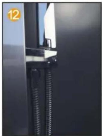
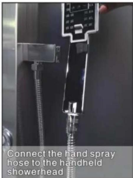
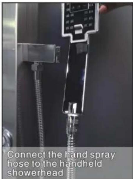
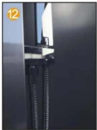
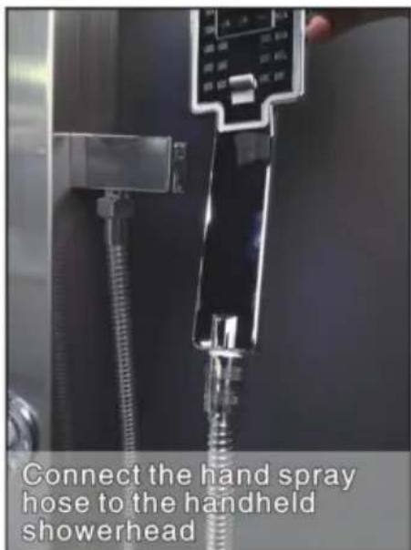
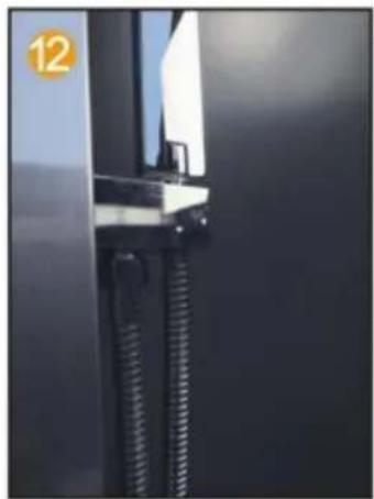
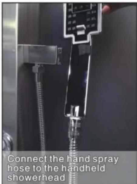
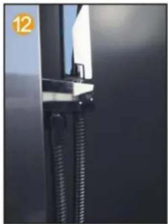
Connect the hand spray hose to the handheld shower head.

MODEL 8004FL

Interior view of a stainless steel appliance with a digital display and control panel (no visible text or symbols).

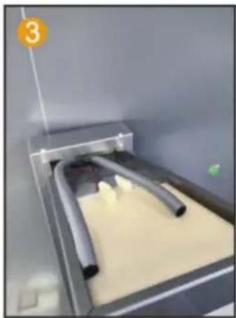
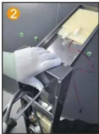
Insert the top spray into the motherboard inside the hole

Person in gloves handling a device with wires and components (no visible text or symbols).

Use 2 M4 screws to secure the main Fixed plate and top spray

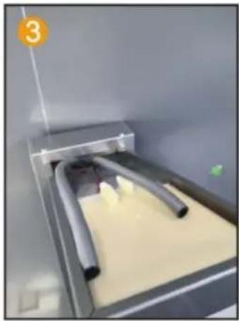
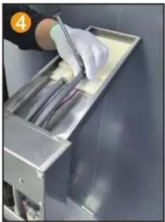
Close-up of a laboratory setup with two tubes inserted into a container, no visible text or symbols.

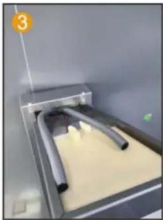
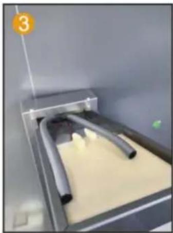
Connect PVC pipes and LED light wires Thread through the hole

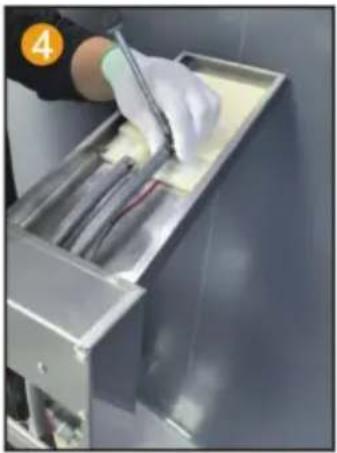
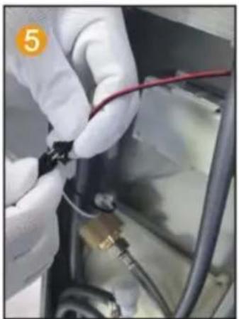
Close-up of a gloved hand using a tool to clean or inspect internal components (no visible text or symbols)

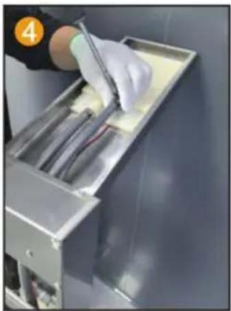
Fix the PVC pipe with a throat clamp On the top spray joint

Close-up of gloved hands installing or adjusting a black cable with red wire, no visible text or symbols

Connect the LED light cable and power supplyline

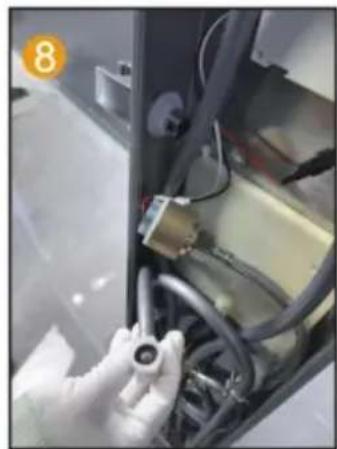
Close-up of a metallic connector with threaded shaft and red cable, no visible text or symbols

Insert the hand spray nozzle into the panel and install the gasket

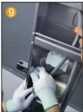
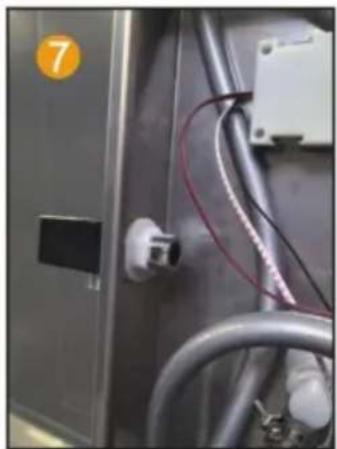
Close-up of industrial equipment with coiled cables and a numbered label (7), no readable text or symbols present.

Spray socket with hexagonal nut handle Fixed on the panel

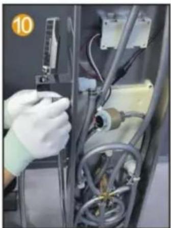
Close-up of hands holding a small mechanical component inside a device (no visible text or symbols)

Spray socket with hexagonal nut handle Fix the 4-point rubber on the panel and spray it by hand Inside the joint of the seat

Person in gloves installing or adjusting a device inside a stainless steel enclosure (no visible text or symbols)

Connect the water outlet connector and hand spray Seat joint

Close-up of gloved hands operating a mechanical device with visible wiring and components (no text or symbols)

Connect the hand spray hose to the handheld one shower head

MODEL 7009FL

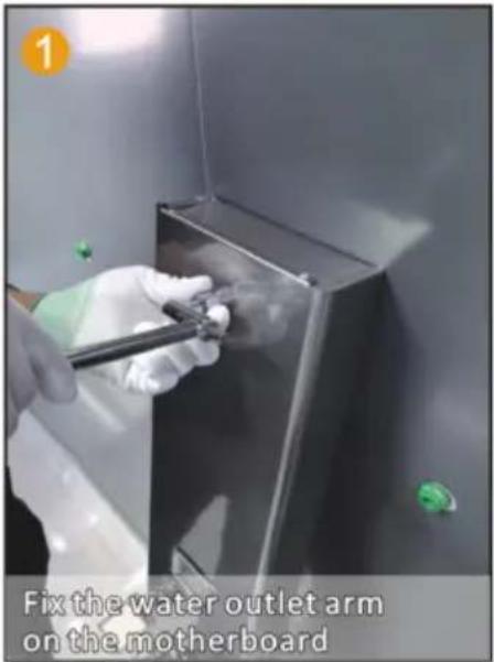
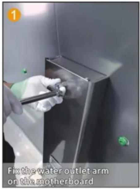
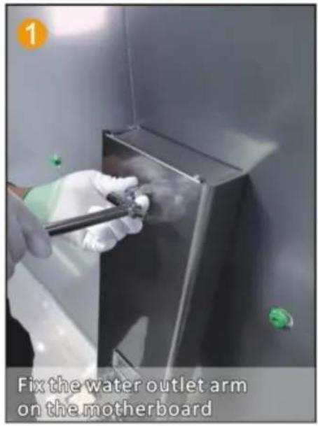
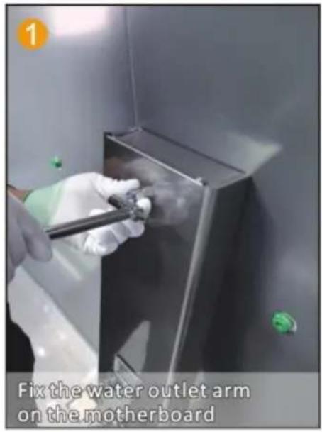
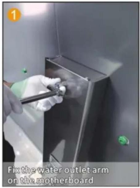
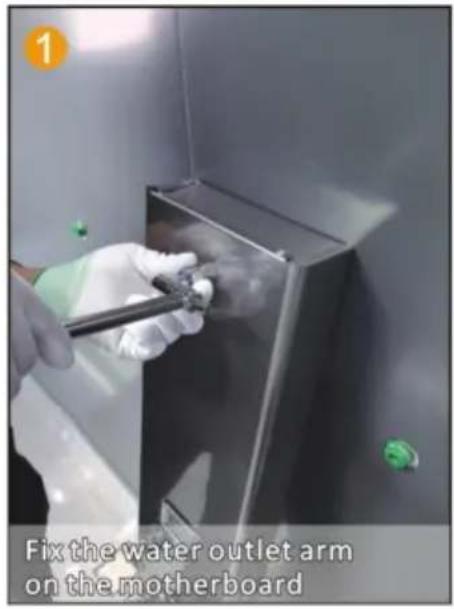
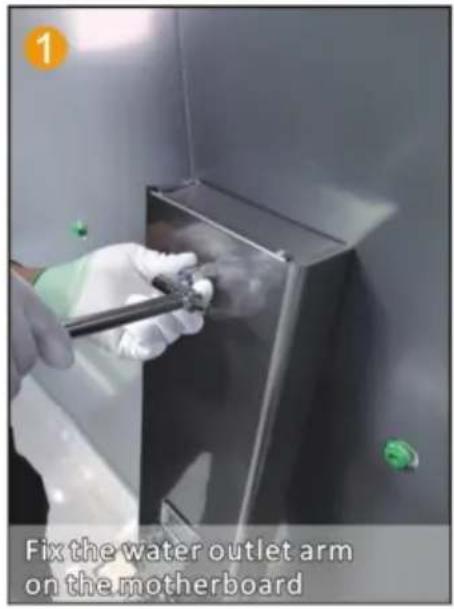
Fix the water outlet arm on the motherboard

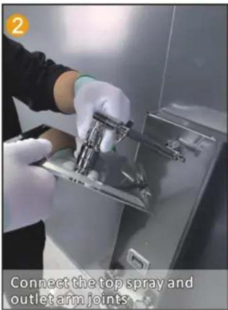
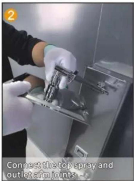
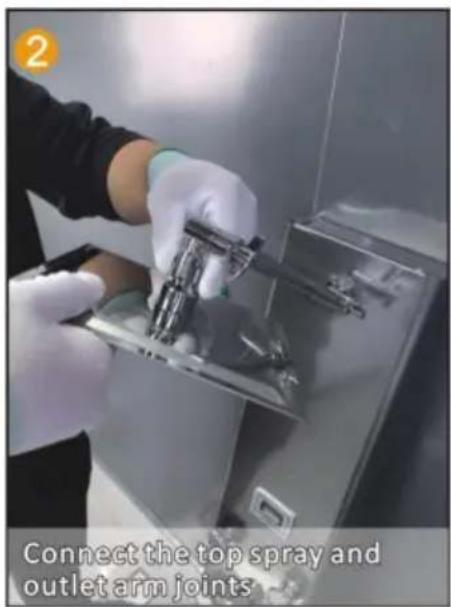
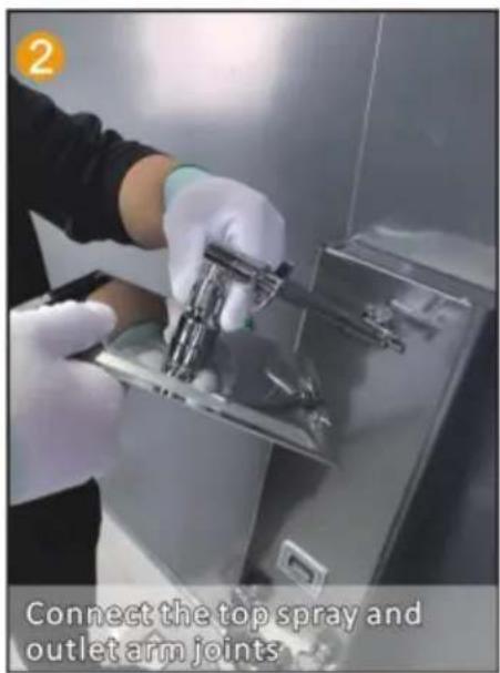
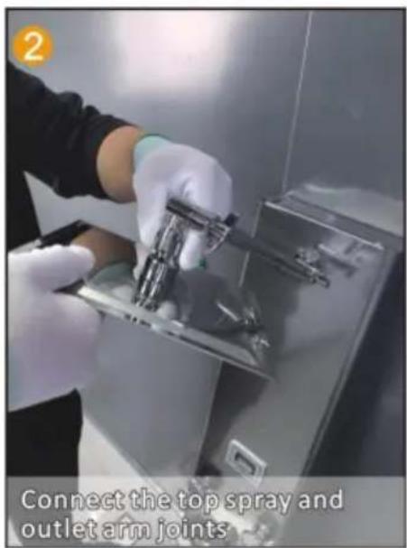
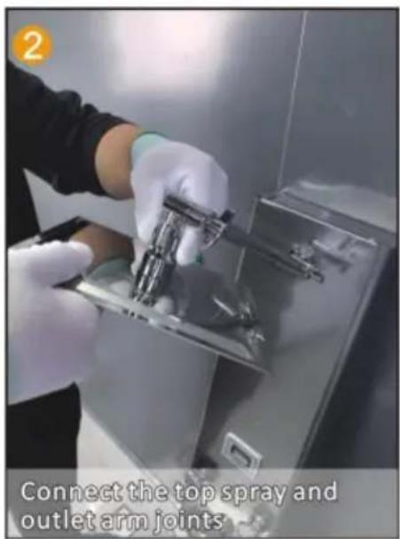
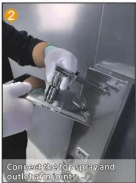
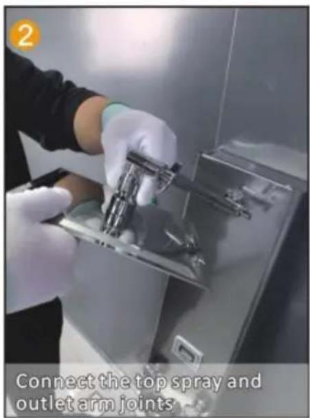
2. Connect the top spray and outlet arm joints

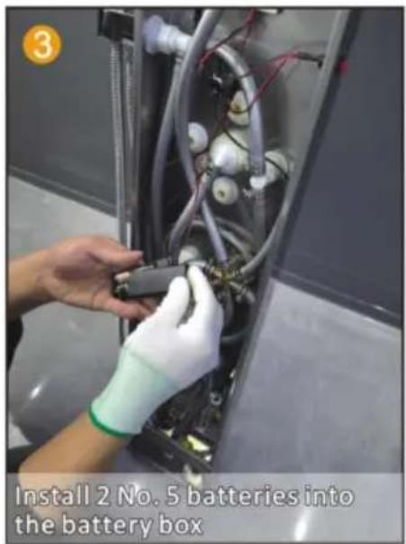
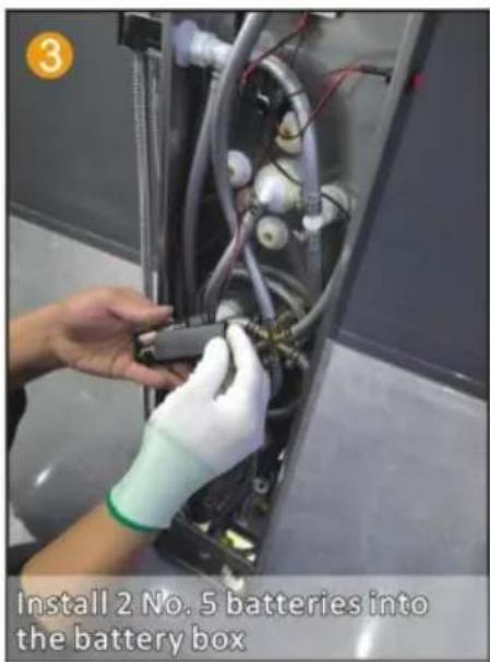
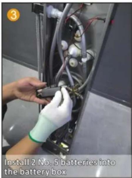
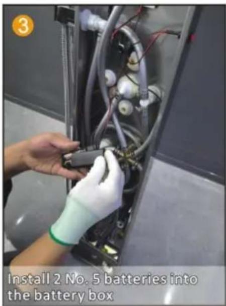
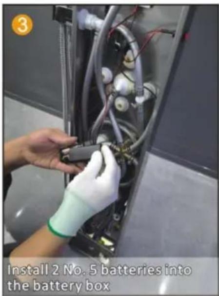
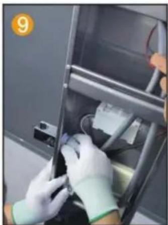
Install 2 No. 5 batteries into the battery box

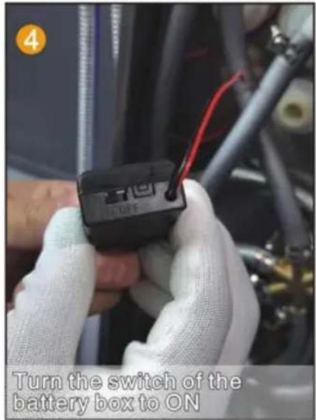
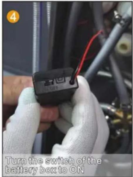
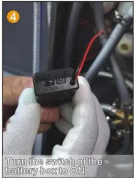
Turn the switch of the battery box to ON

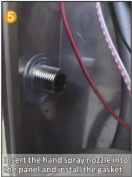
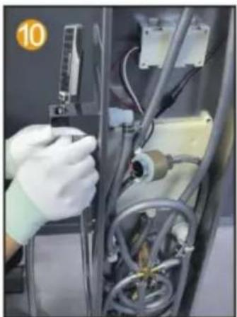
Insert the hand spray nozzle into the panel and install the gasket

Spray socket with hexagonal nut handle fixed on the panel

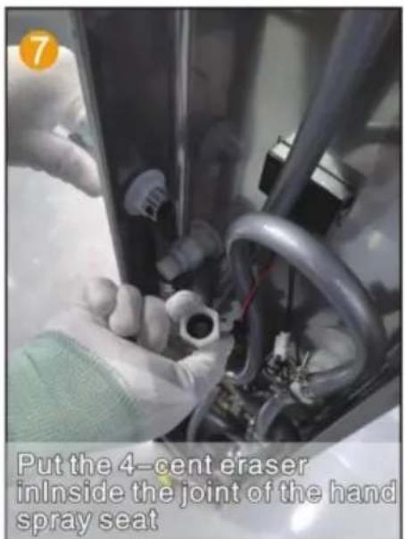
7. Put the 4-cent eraser inside the joint of the hand spray seat

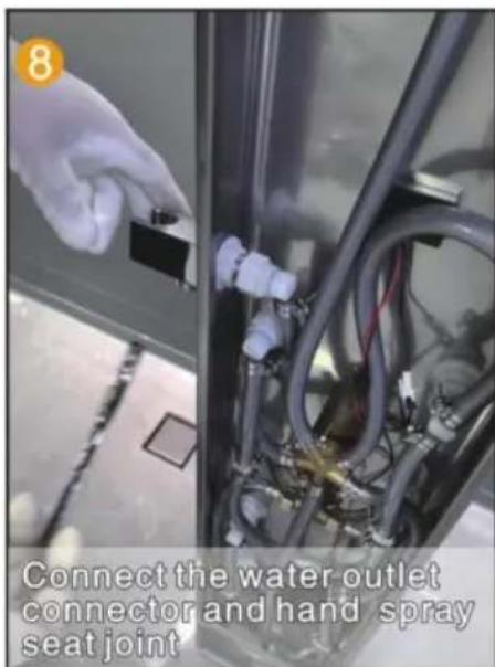
8. Connect the water outlet connector and hand spray seat joint

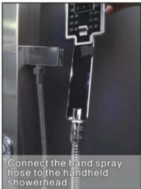
Connect the hand spray hose to the handheld showerhead.

INSTALLATION STEPS (GENERAL)

Vevor 8039FL - INSTALLATION STEPS (GENERAL) - 1

Installation Notes

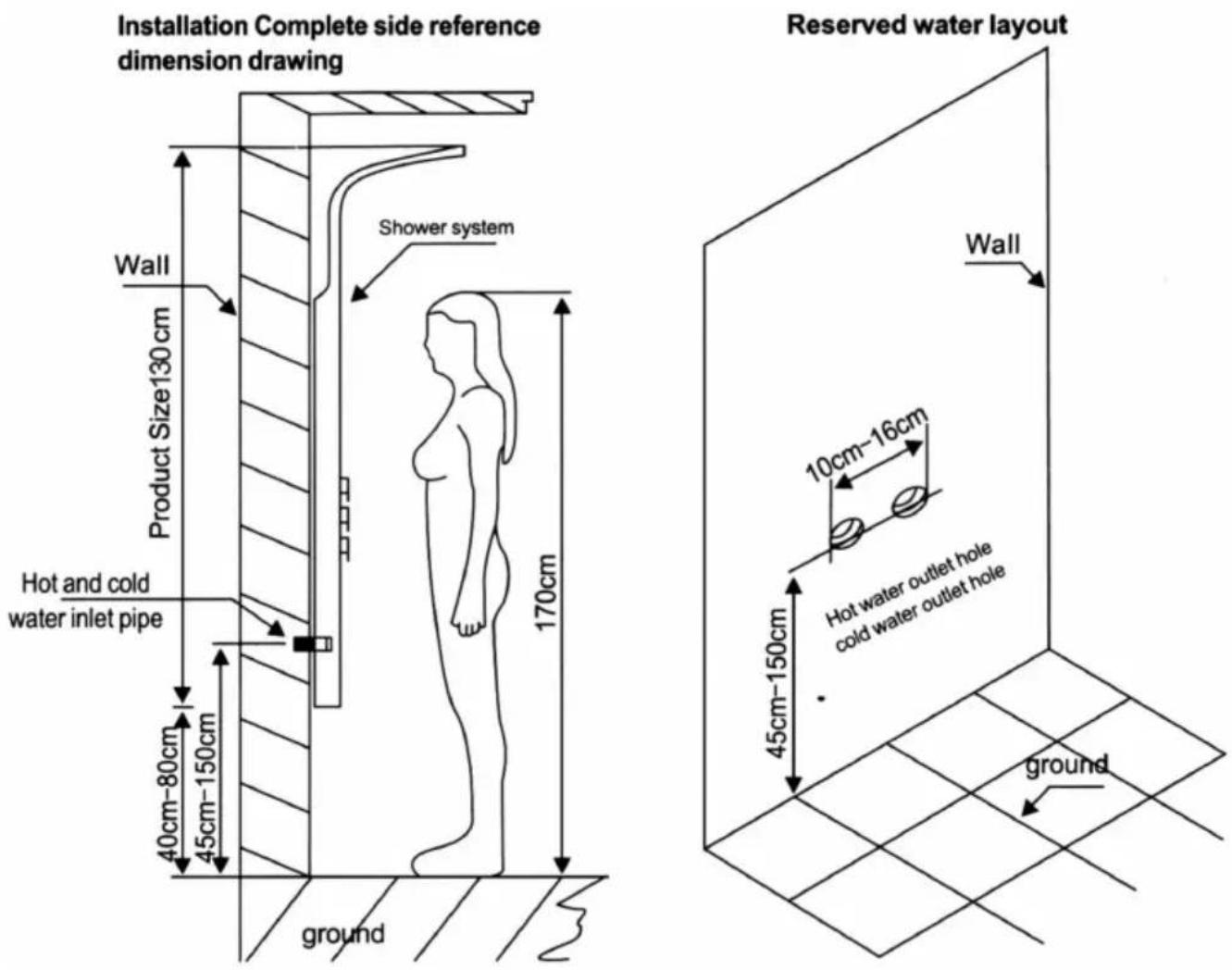
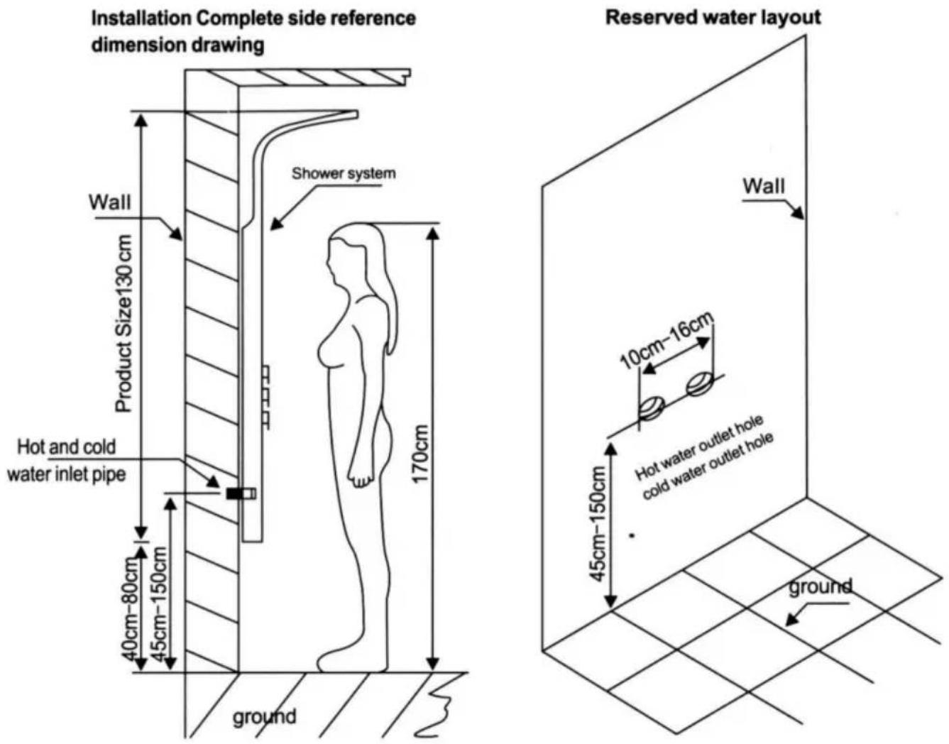
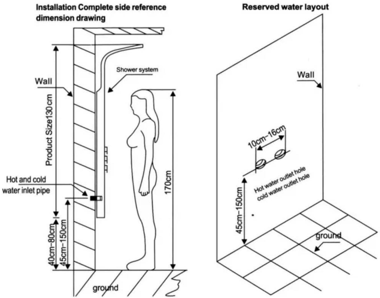
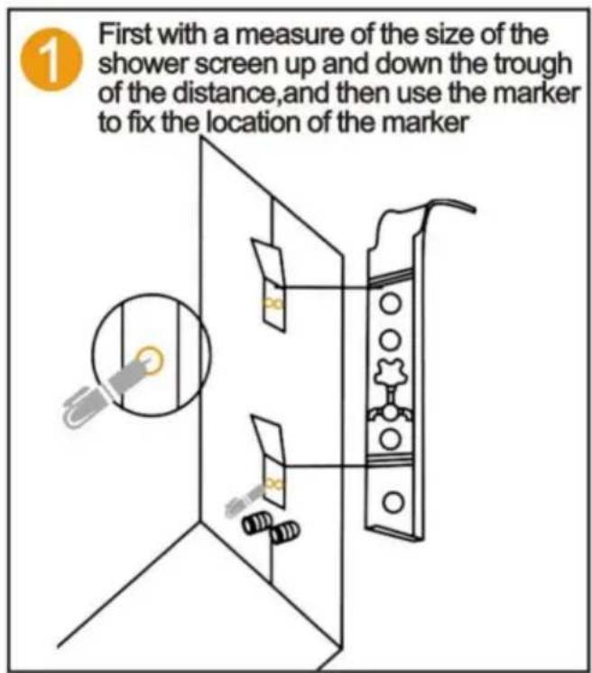
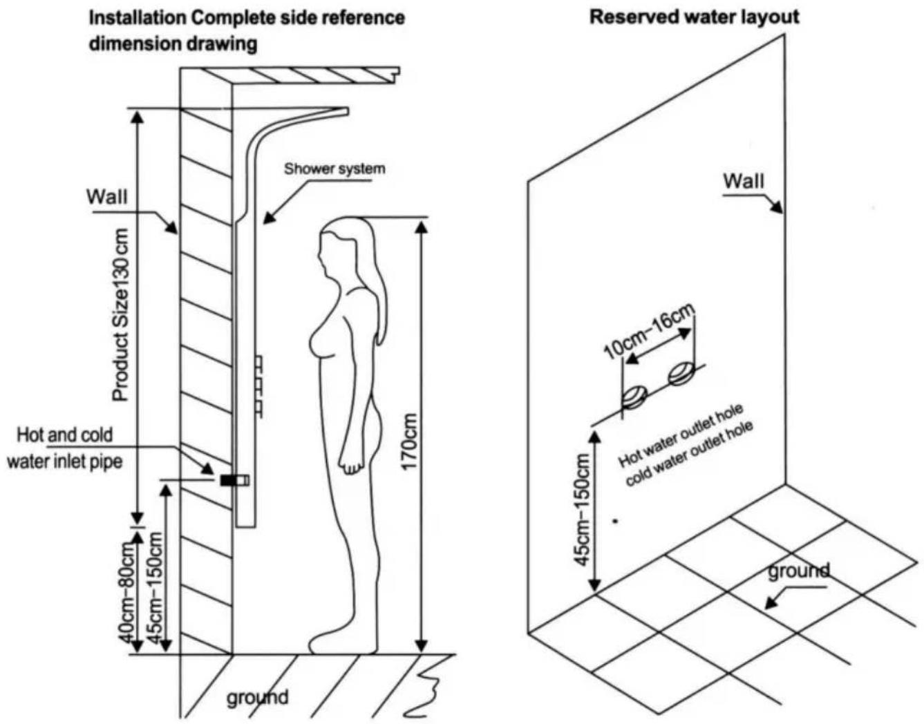
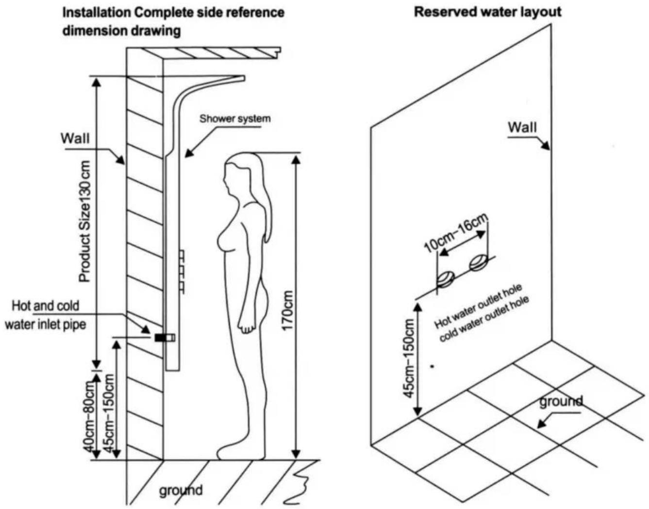
  1. According to the height of the family height budget shower system installation height, measure the shower system on the back of the bar Distance, mark a wall, in the corresponding position of the tag fixed hanging iron (up and down one).
  2. Connect the hot and cold water hoses (be sure to clean the filter and any debris from the wall to prevent blockage and ensure proper water flow).
  3. Hang the shower system on the wall, clamping the upper and lower brackets into the two mounting plates (Note: after mounting the shower system on the wall, the main unit should be close to the wall without shaking; no additional glass glue or tools are needed for fixing).

Stainless steel shower system maintenance methods:

  1. Regularly clean the product to keep its appearance bright and clean;
  2. Clean the surface with water or a mild detergent and wipe it with a soft cloth.
  3. Note: clean the hidden parts of the product; timely cleaning ensures the product's longevity.

SHOWER PANEL SERIES INSTALLATION DIAGRAM

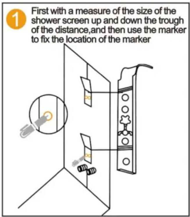
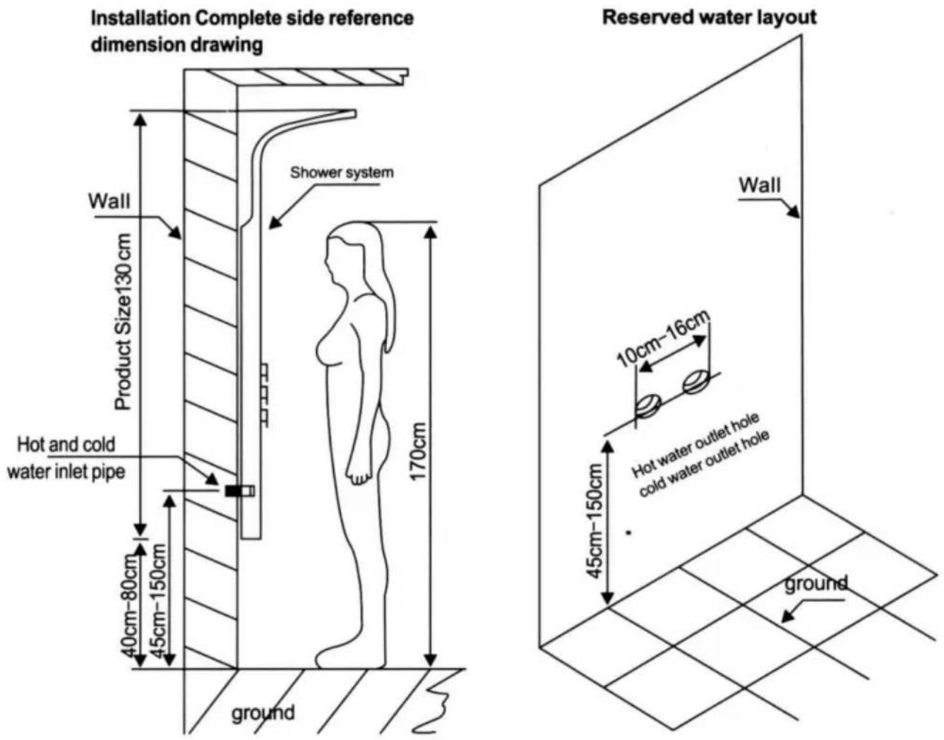
First, measure the size of the shower screen up and down the trough of the distance, and then use the marker to fix the location of the marker.

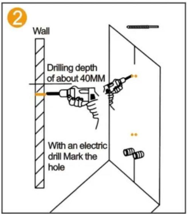
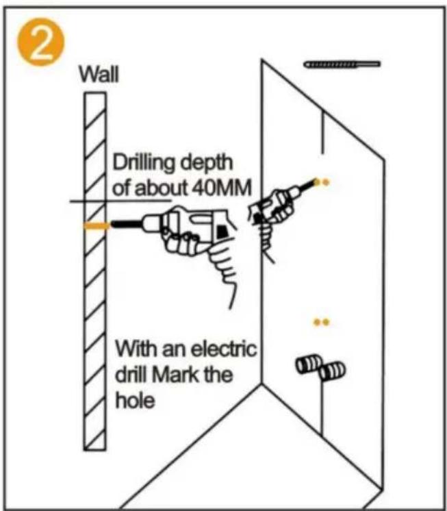
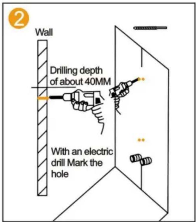
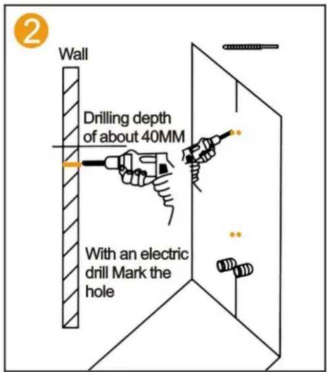
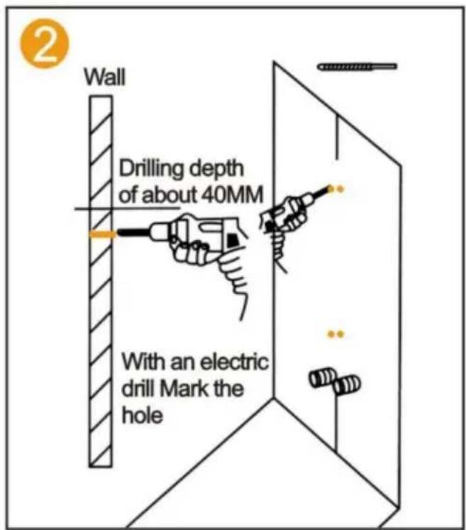
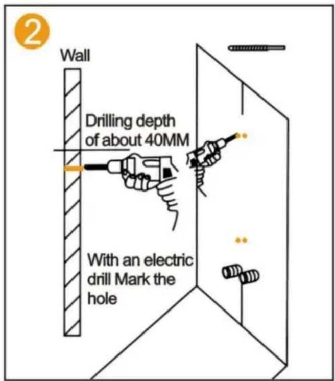
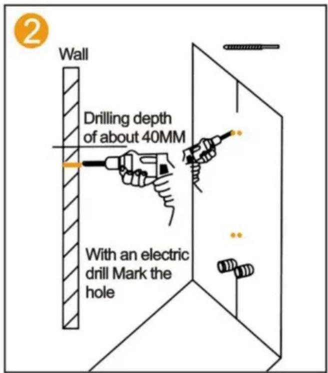
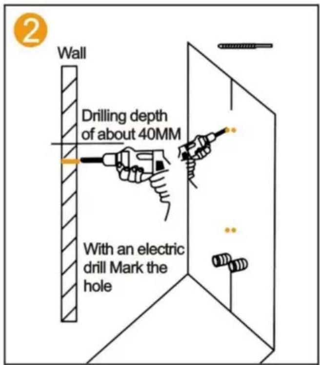
2. Wall. Drilling depth of about 40mm. With an electric drill, mark the hole.

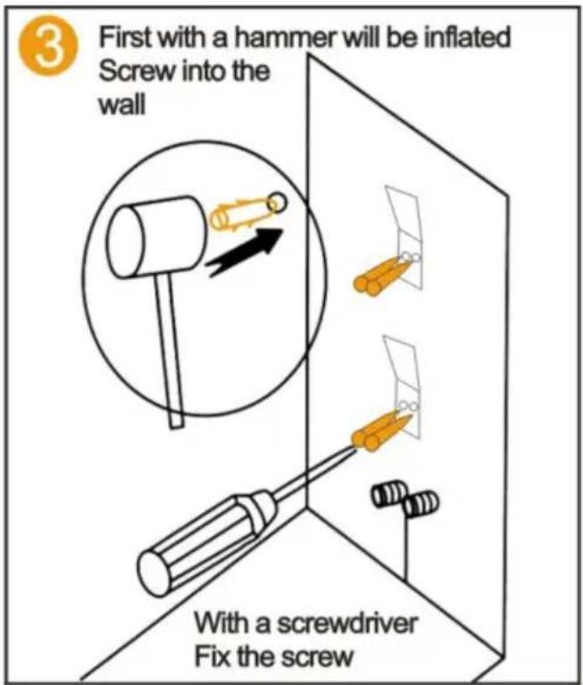
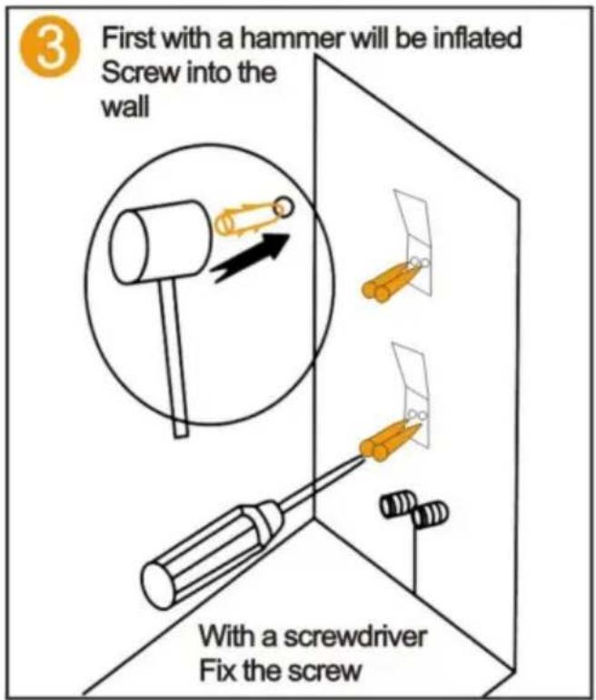
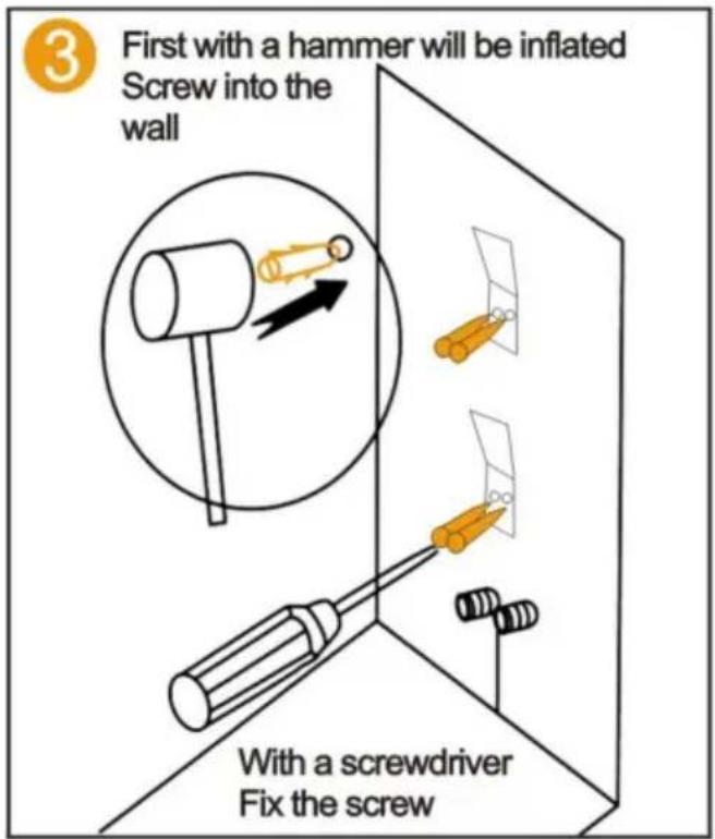
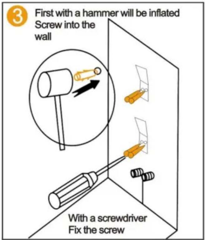
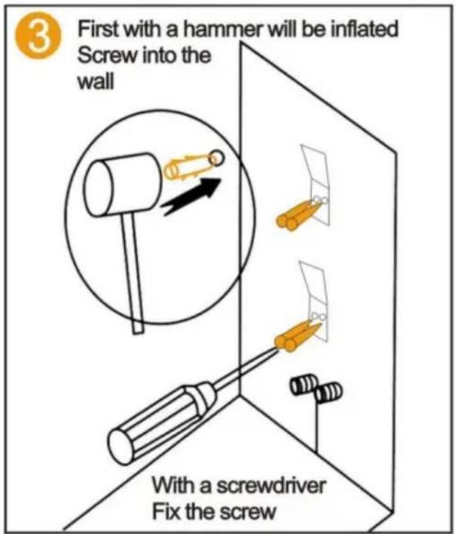
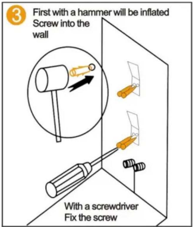
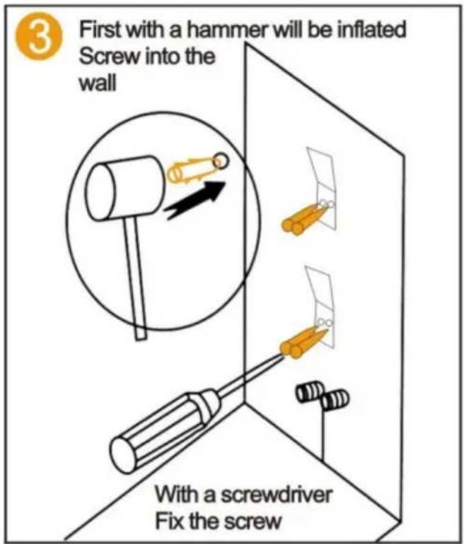
3. First with a hammer, the inflated screw will be screwed into the wall. With a screwdriver, fix the screw.

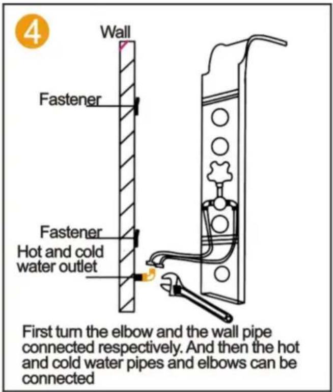
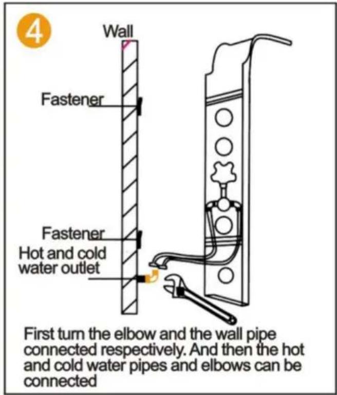
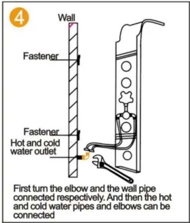
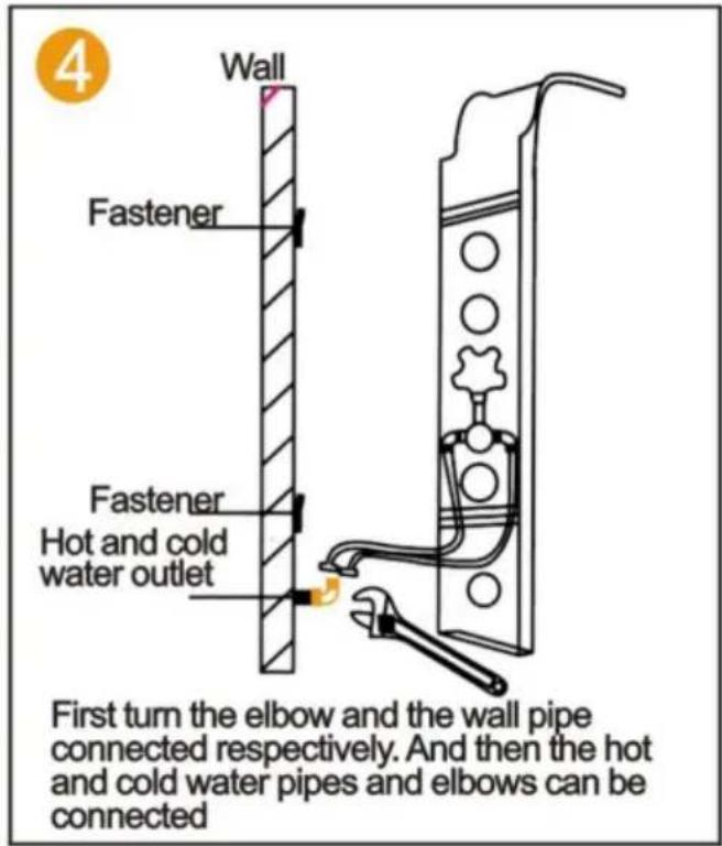
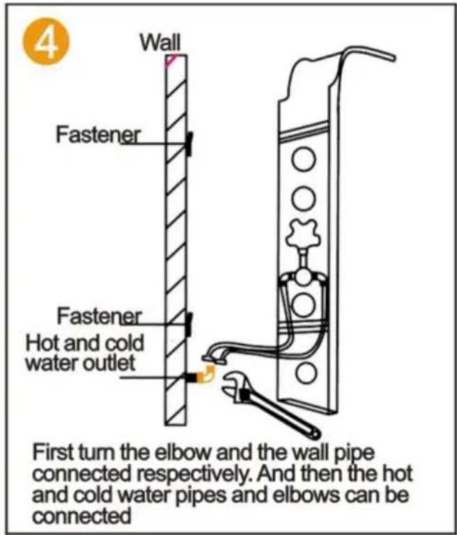
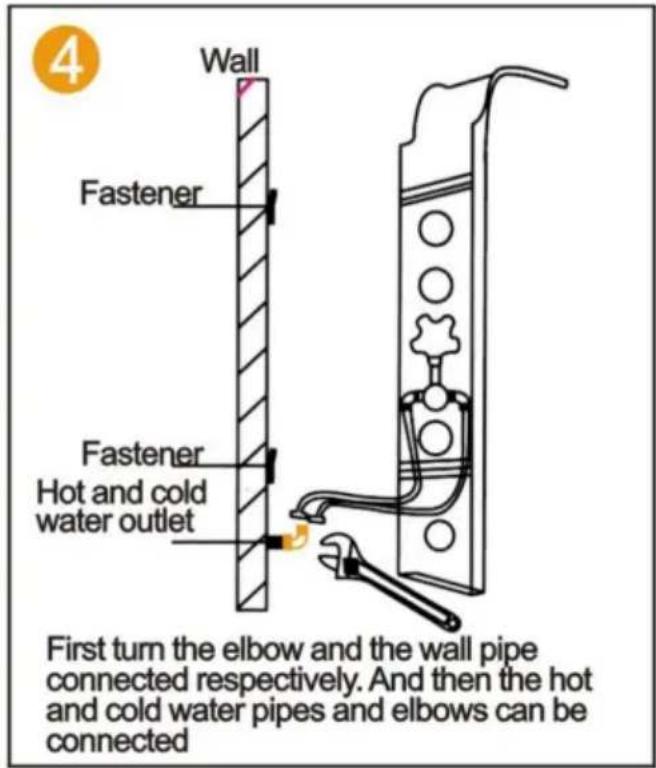
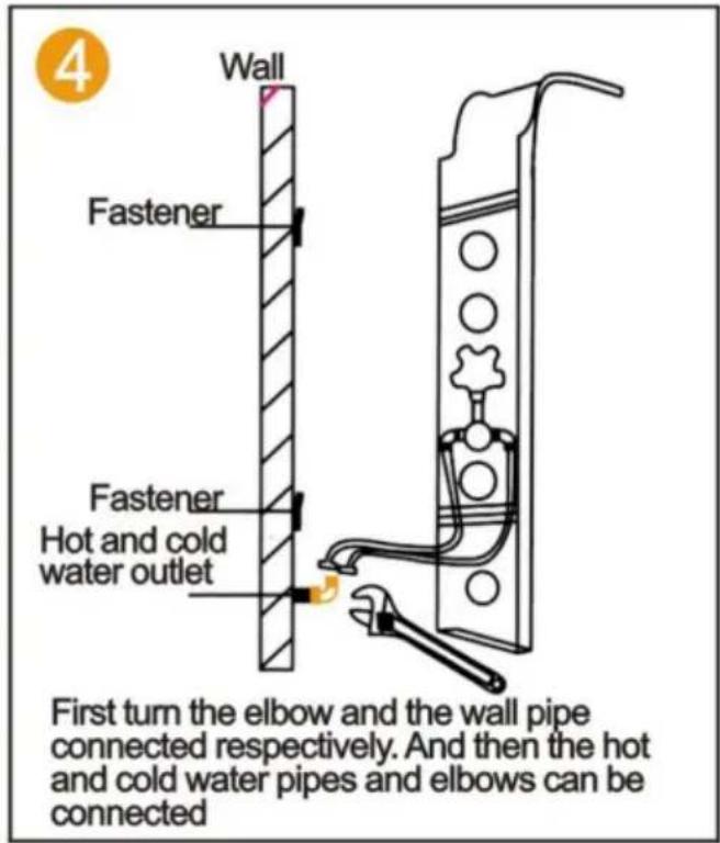
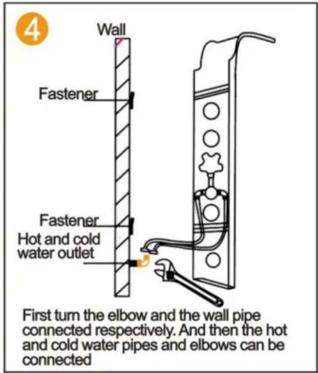
Wall. Fastener. Fastener. Hot and cold water outlet. First turn the elbow and the wall pipe connected respectively. And then the hot and cold water pipes and elbows can be connected.

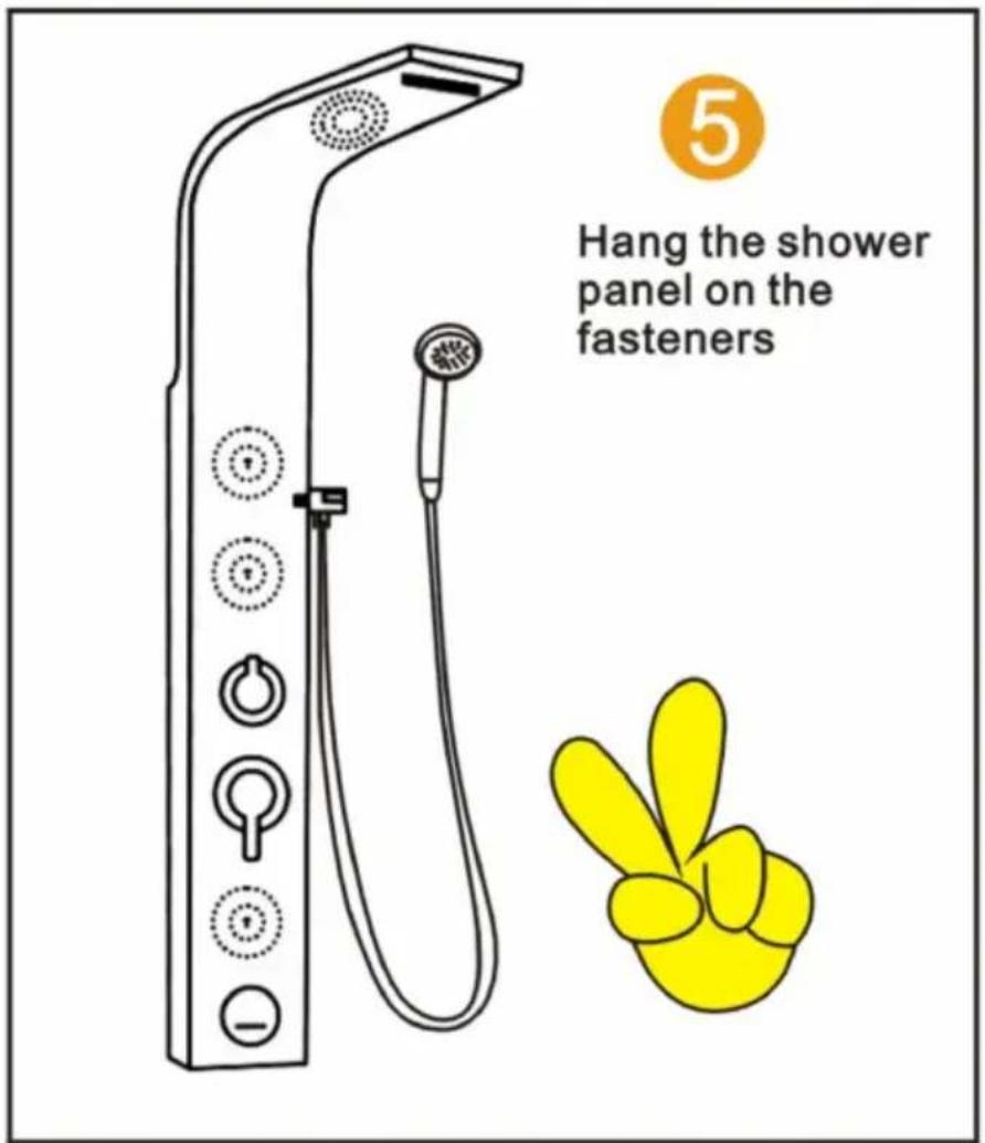
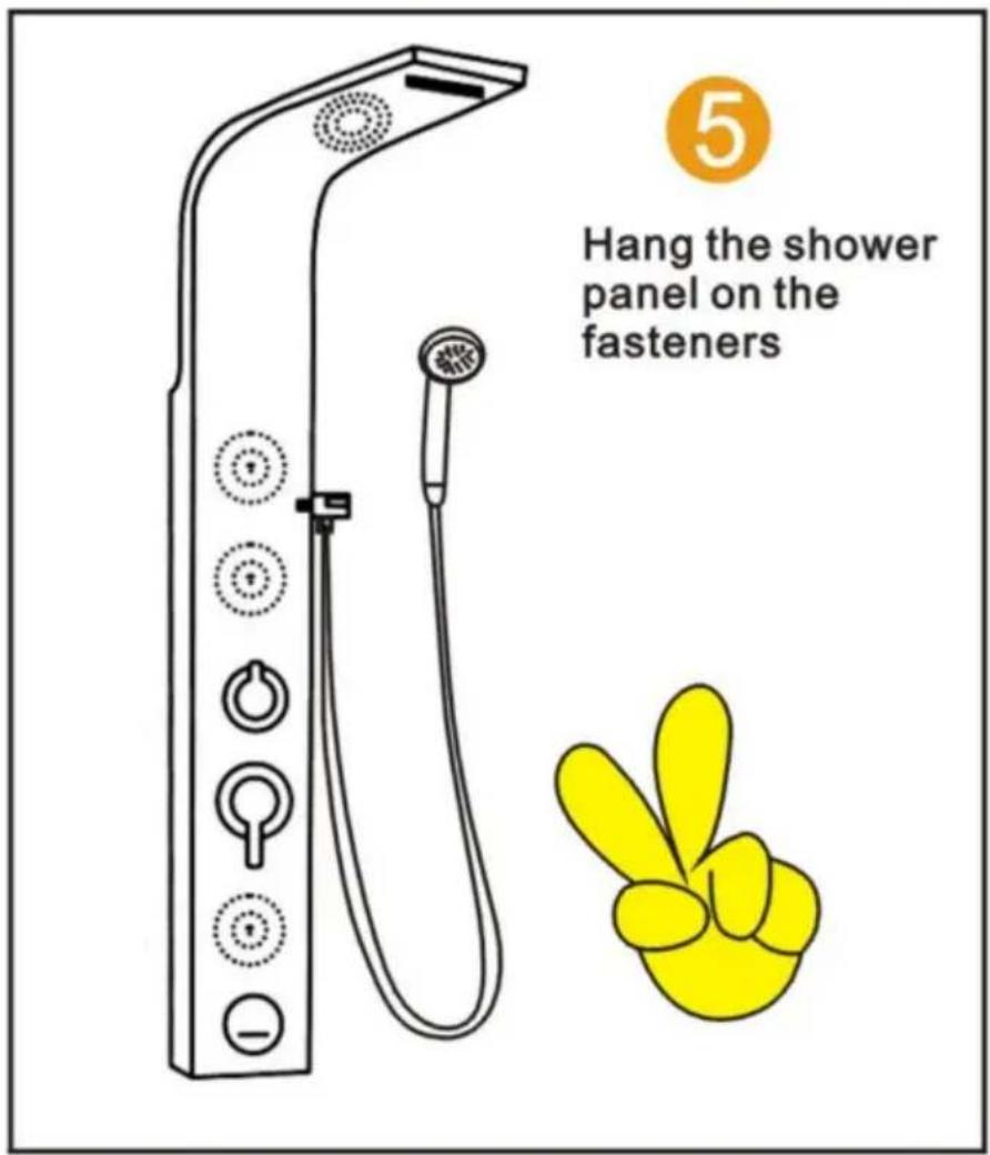
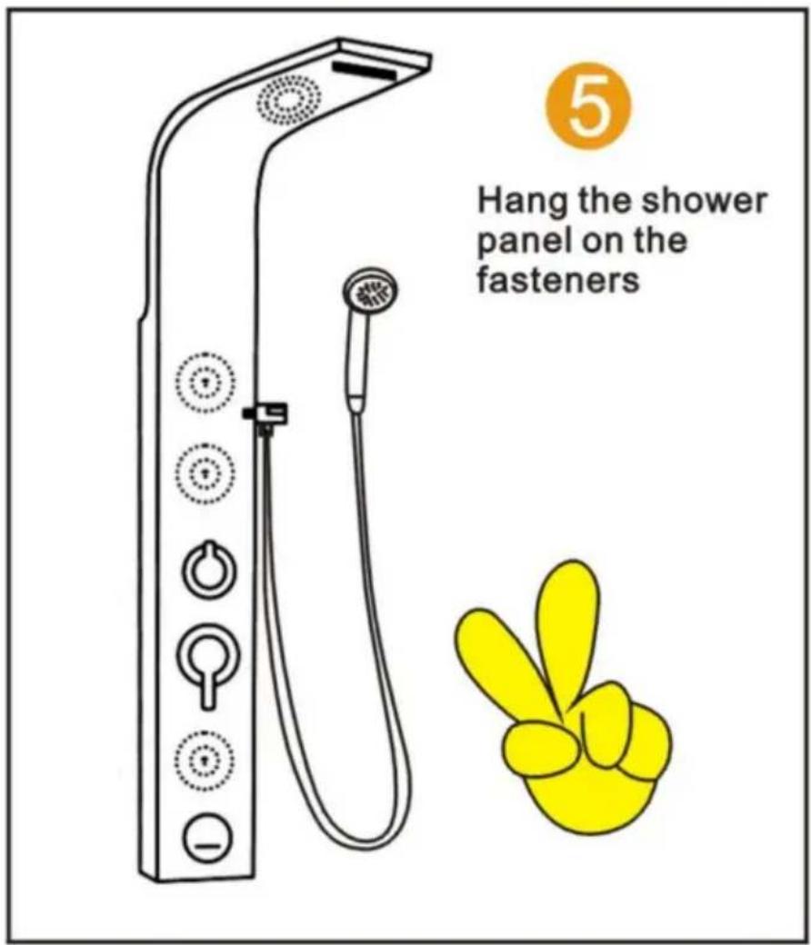
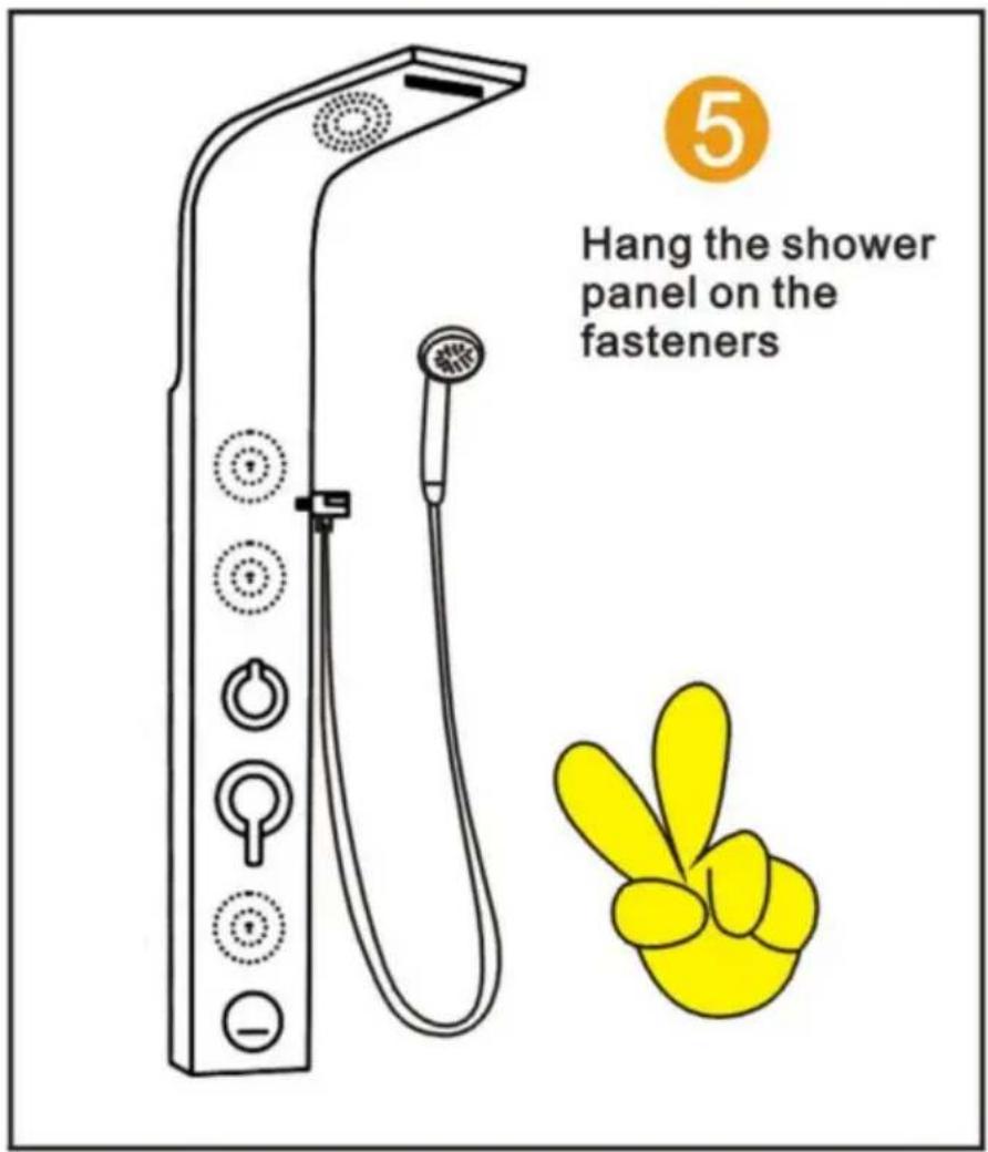
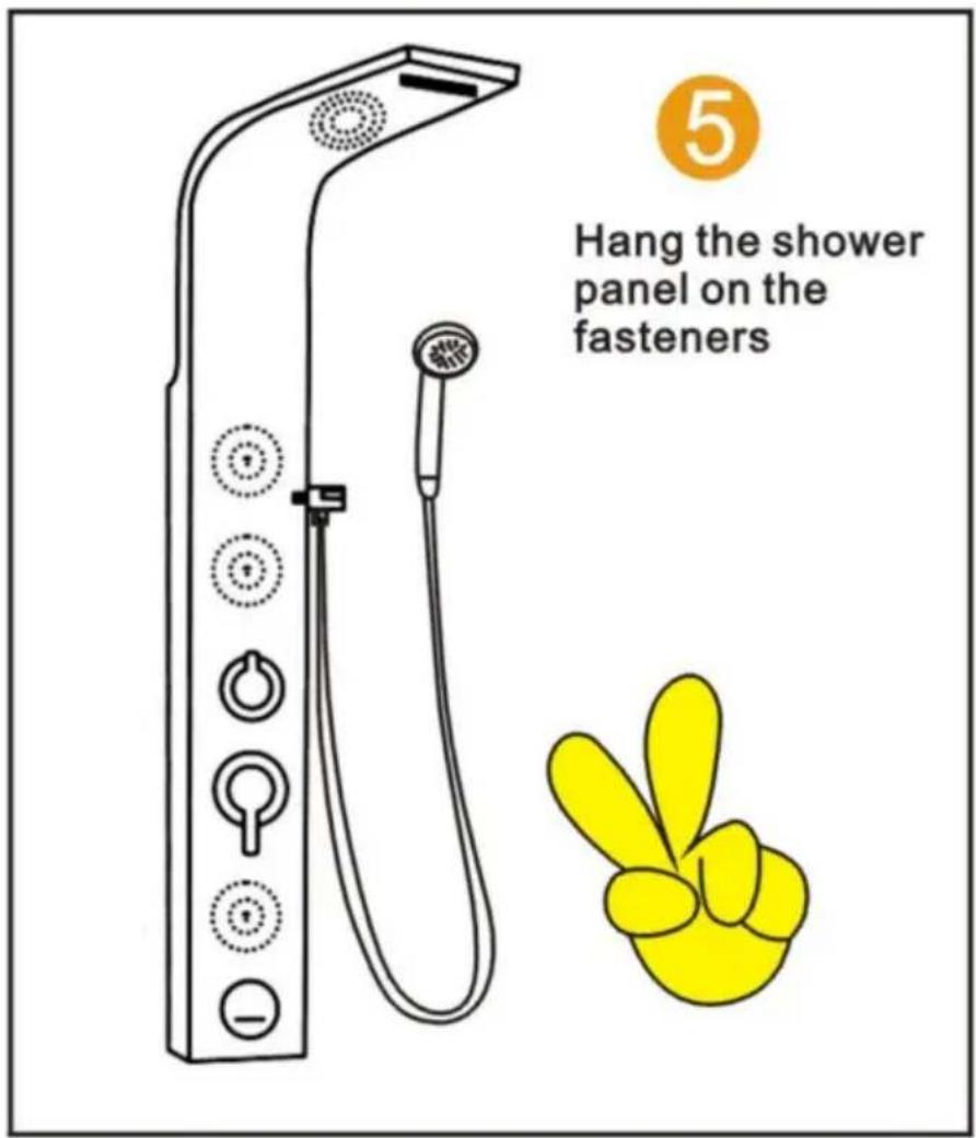
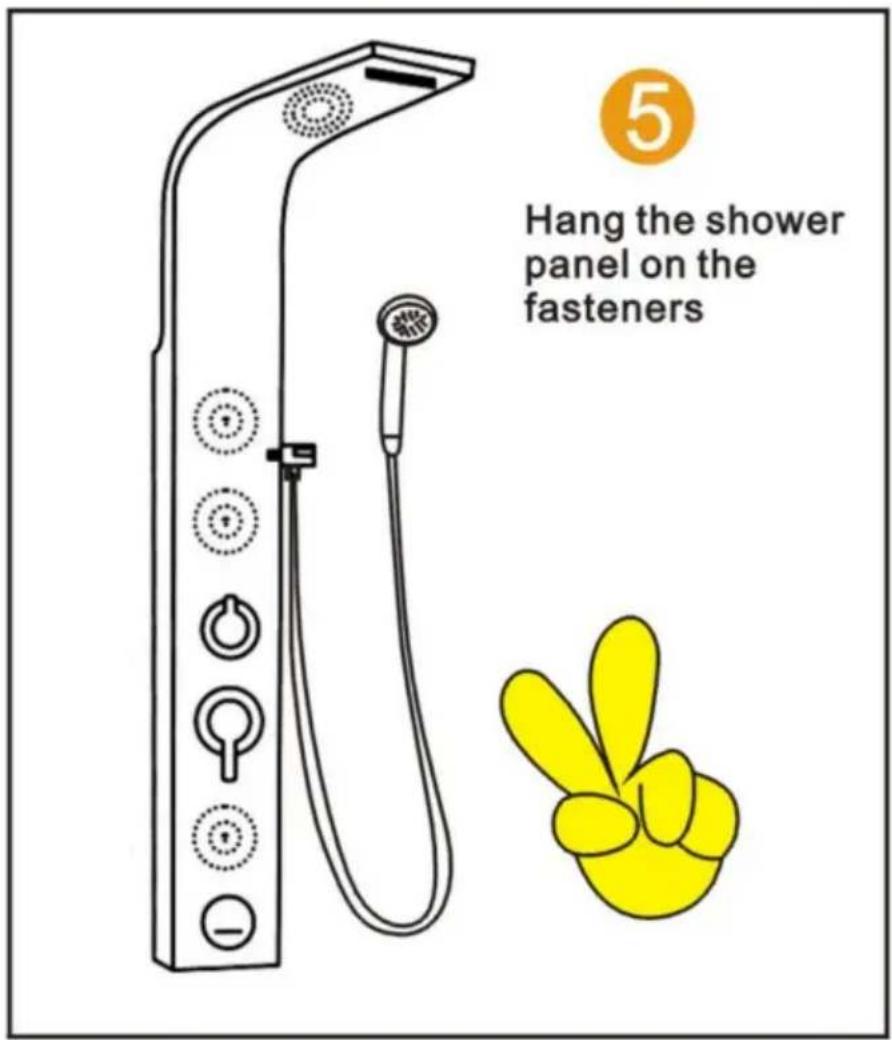
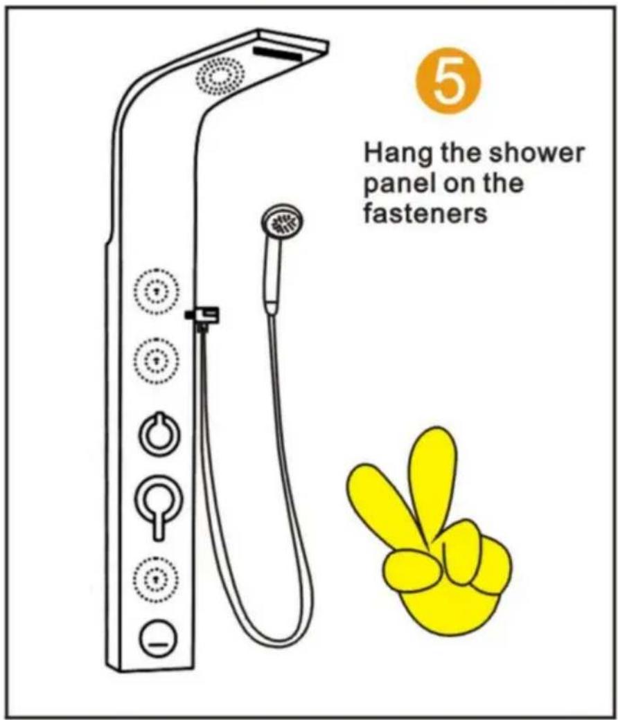
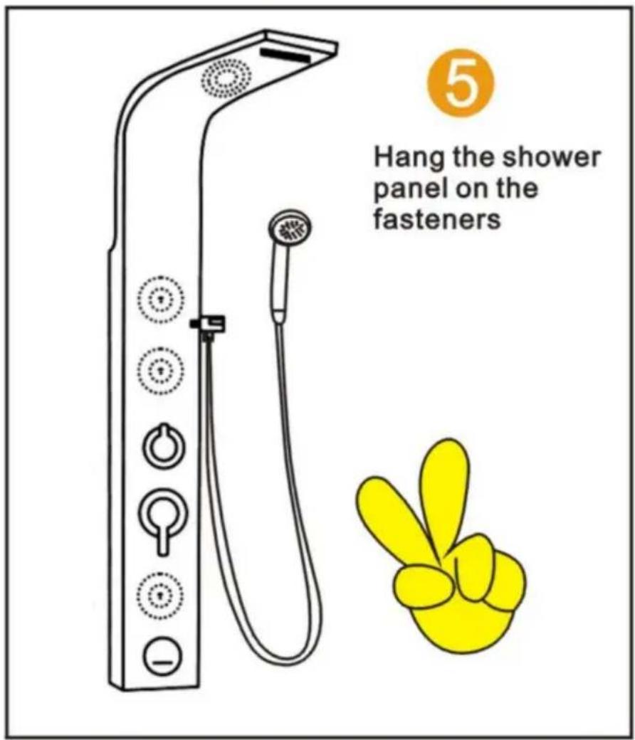
5. Hang the shower panel on the fasteners.

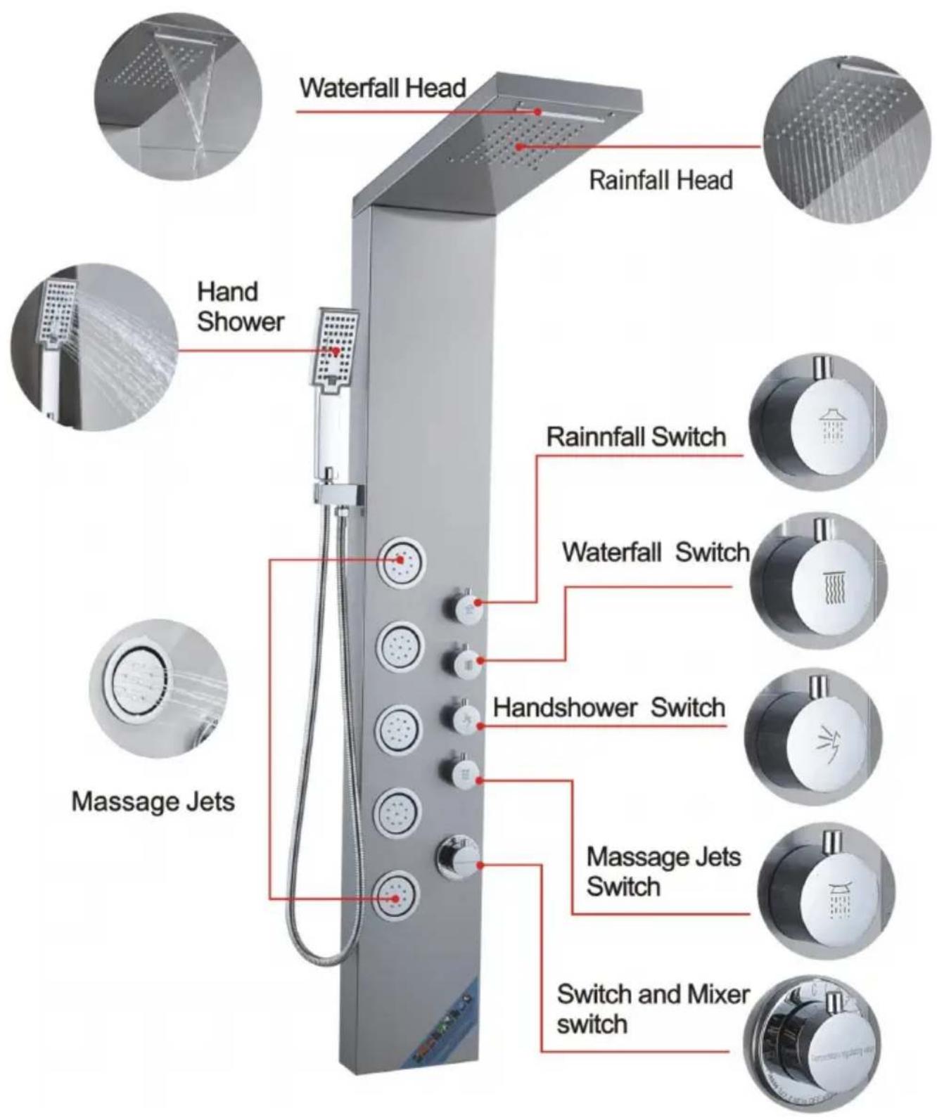
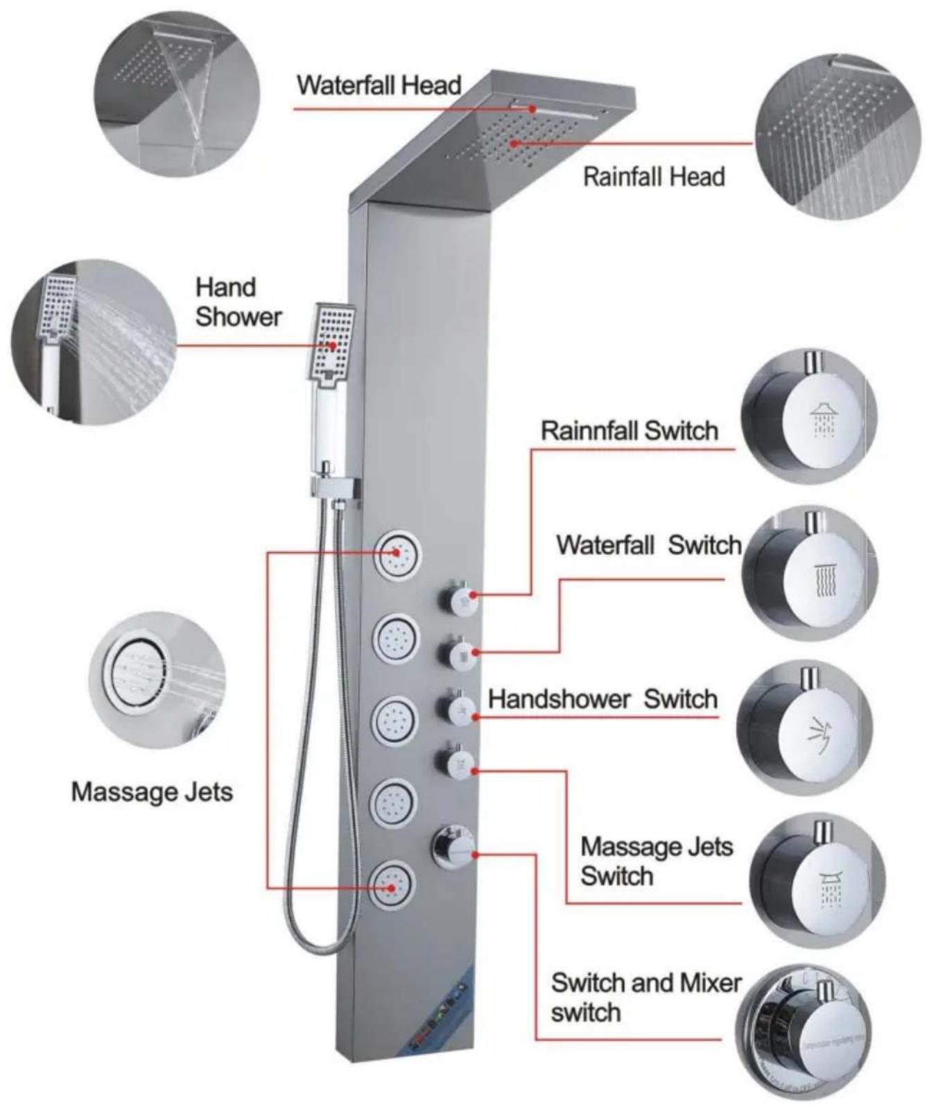
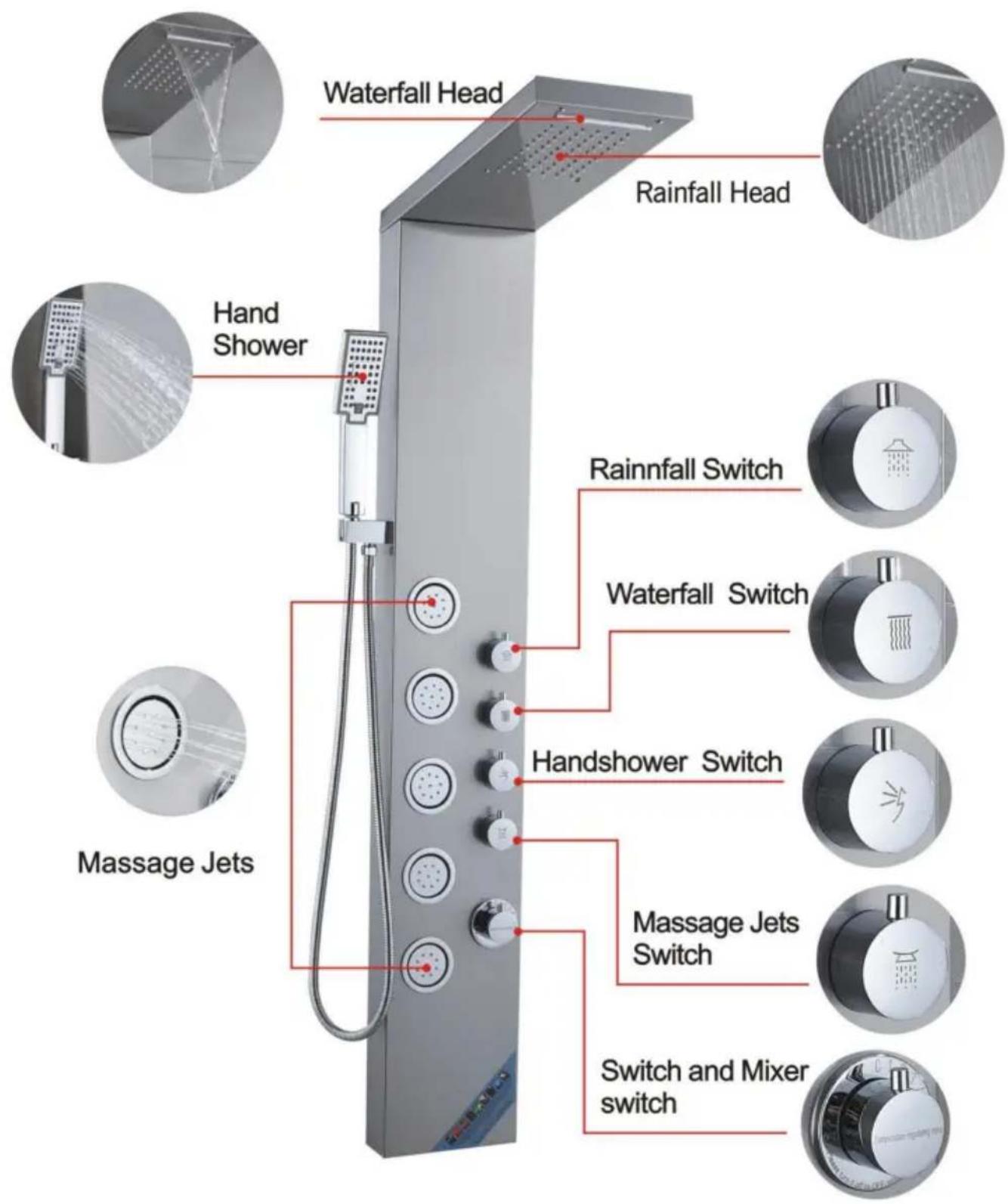
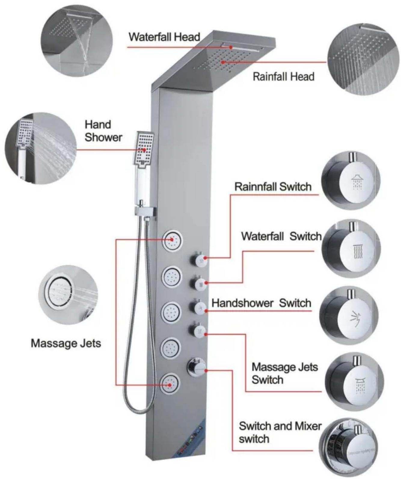
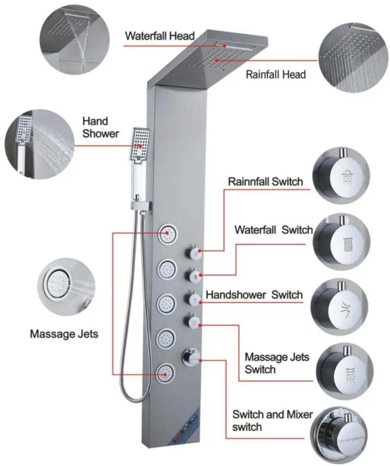
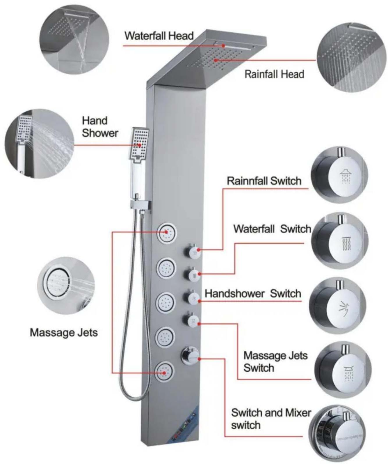
8015FLWaterfall Head, Rainfall Head, Hand Shower, Rainfall Switch, Waterfall Switch, Handshower Switch, Massage Jets, Massage Jets Switch, Switch and Mixer switch.

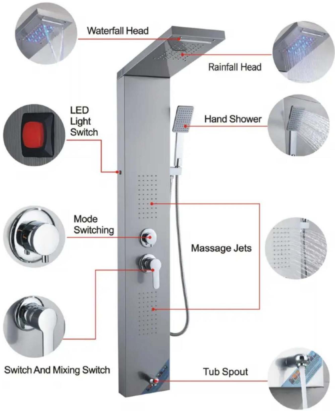
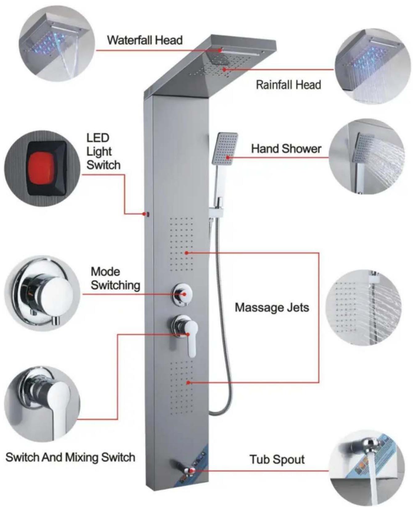
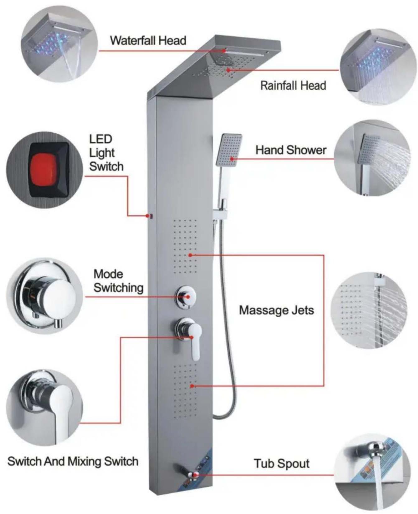
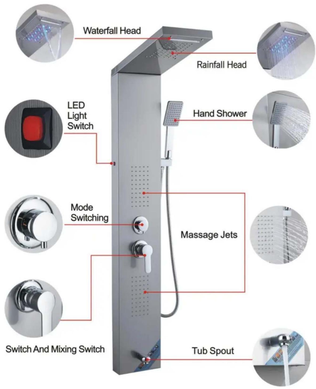
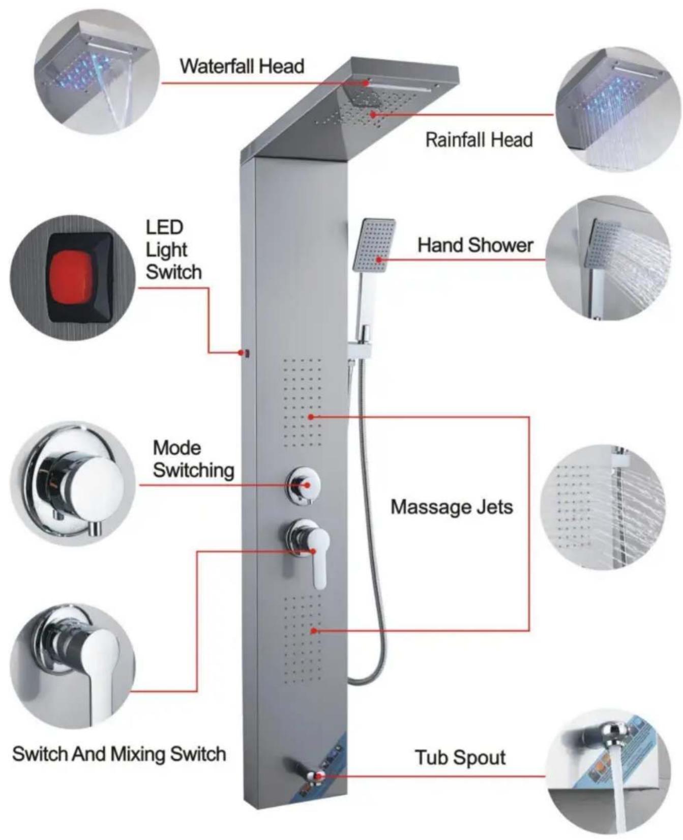
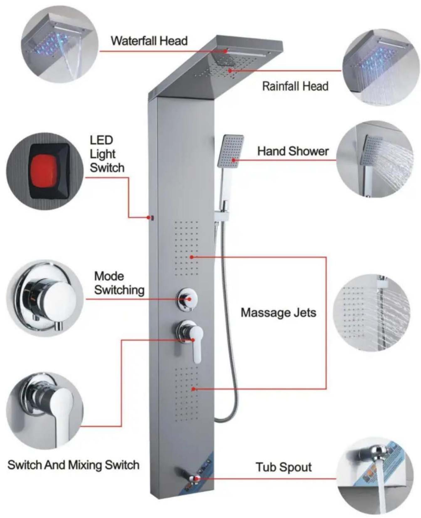
6002FLWaterfall Head, Rainfall Head, LED Light Switch, Hand Shower, Mode Switching, Massage Jets, Switch And Mixing Switch, Tub Spout.

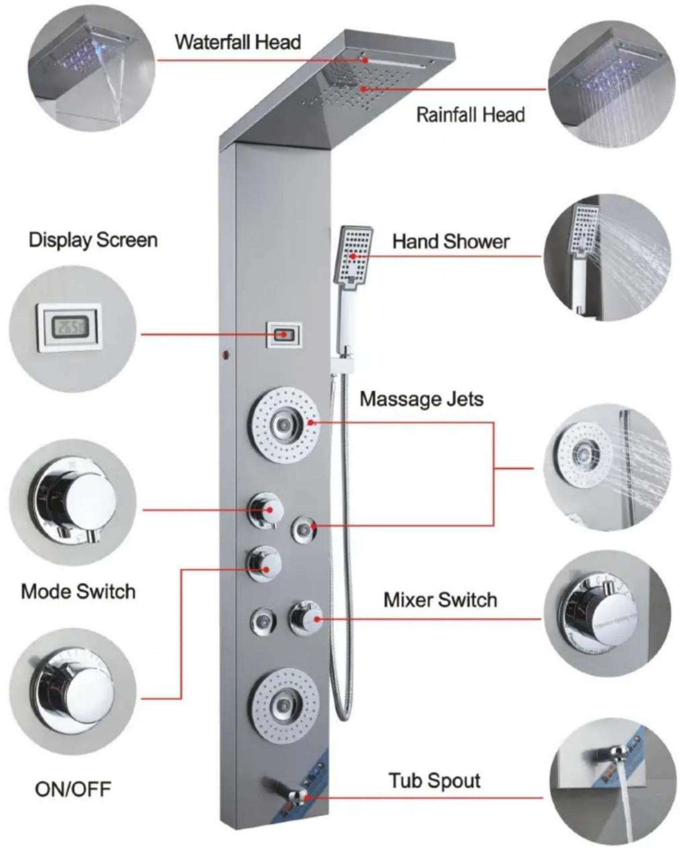
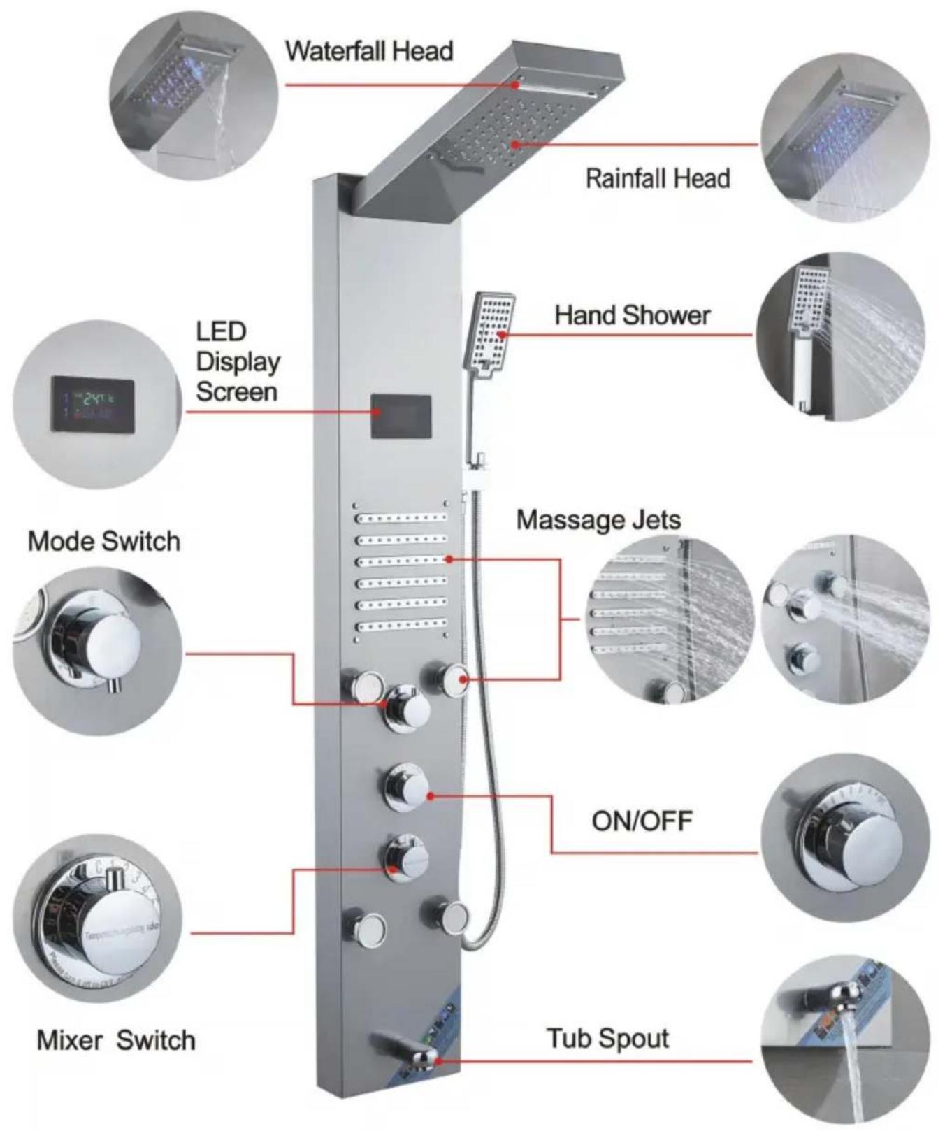
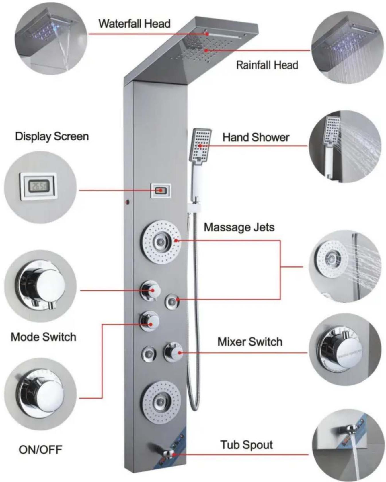
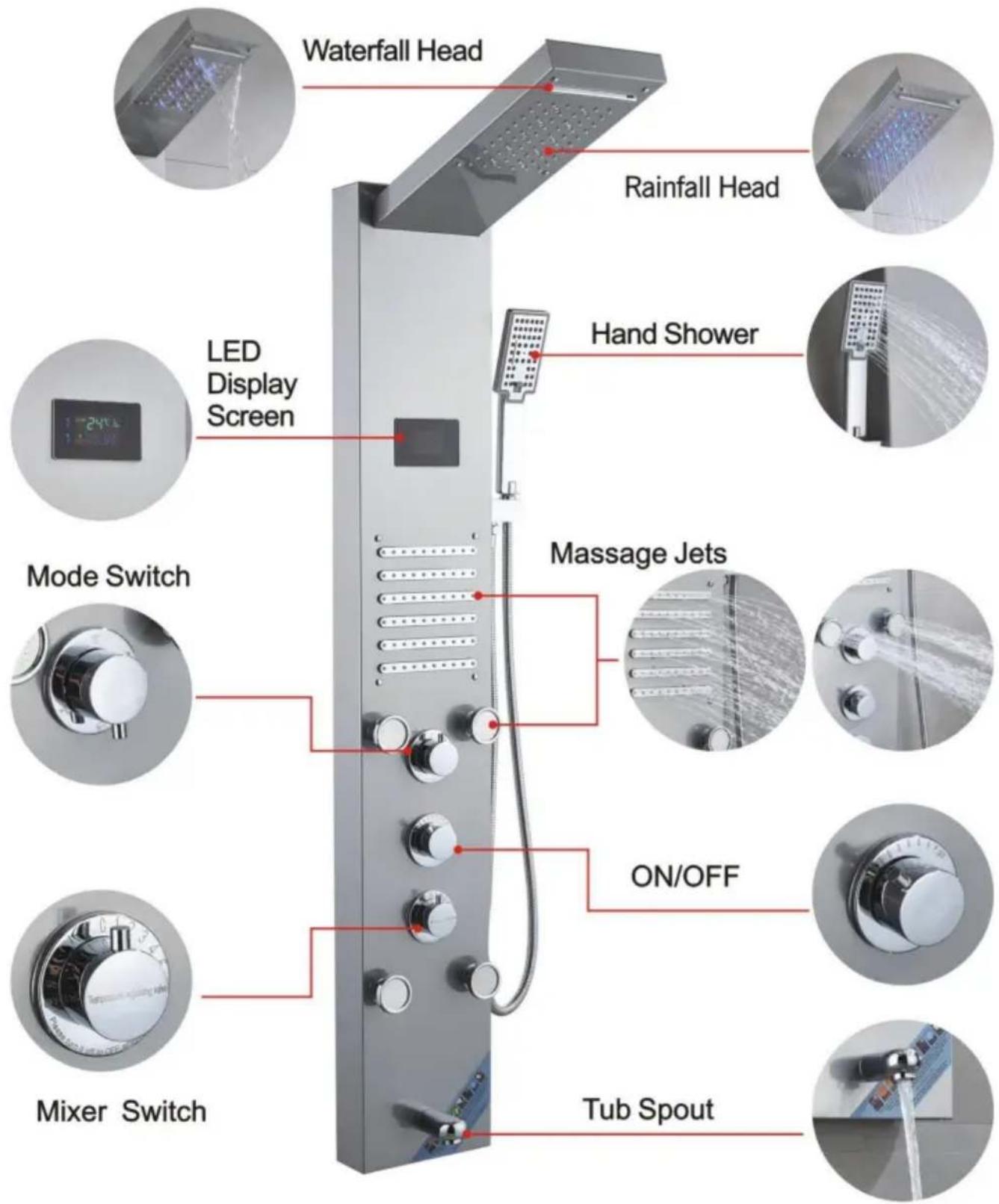
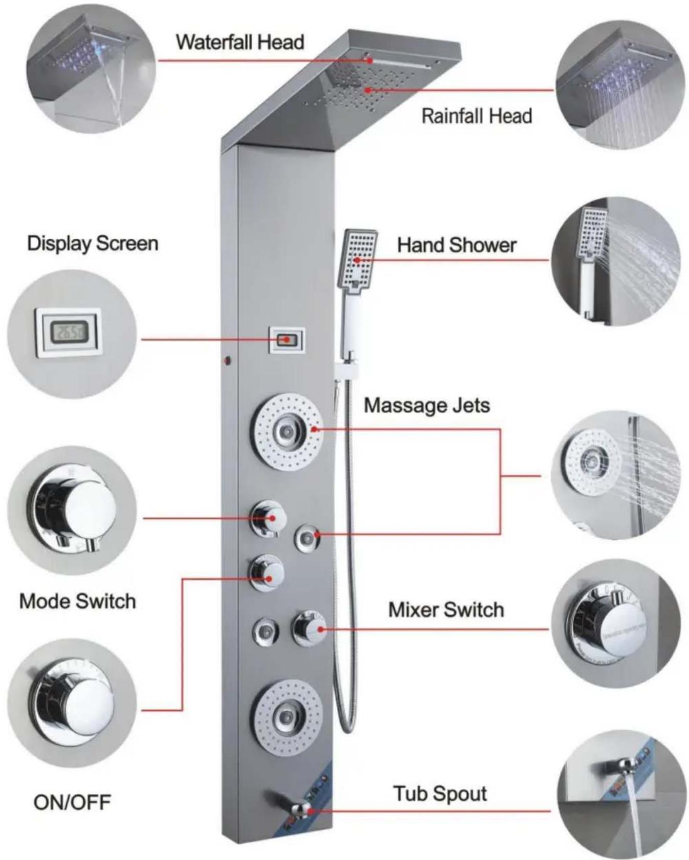
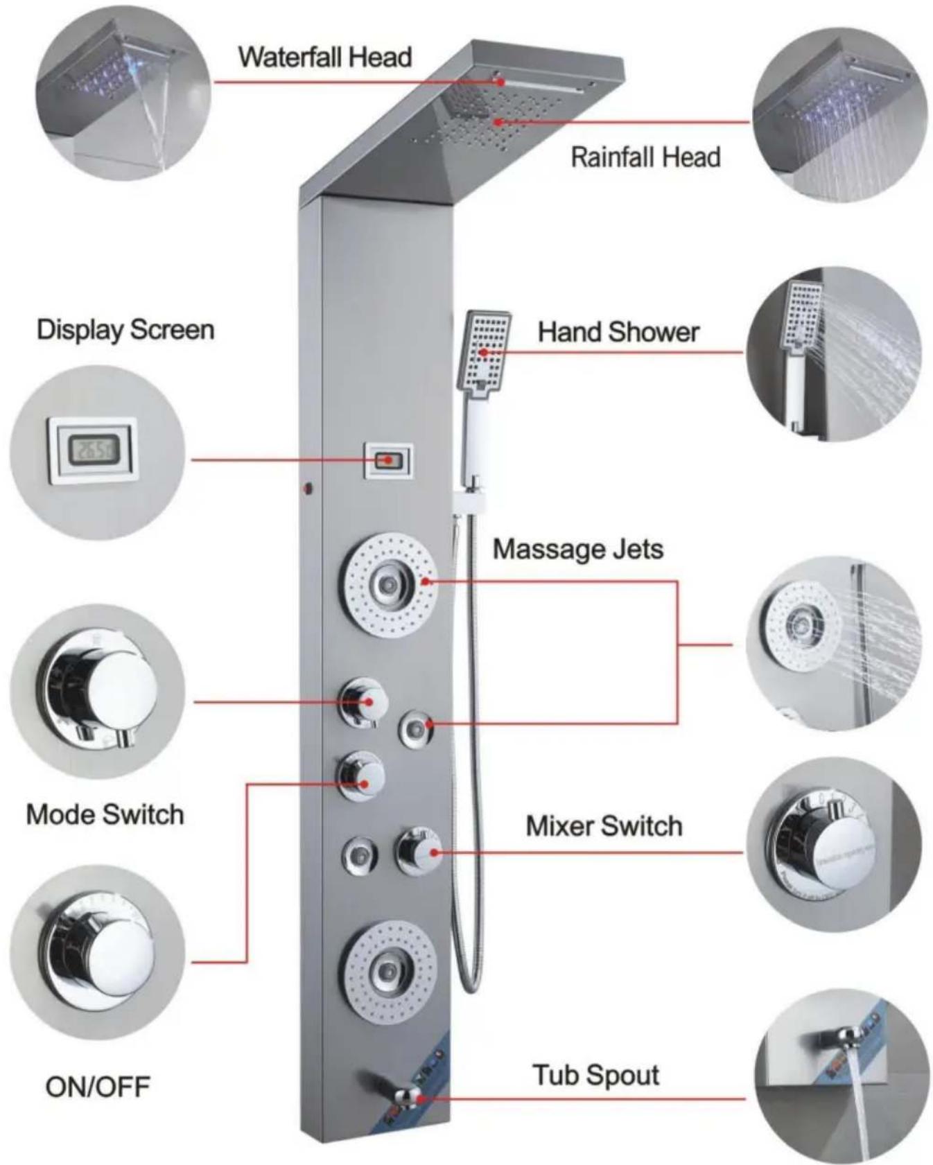
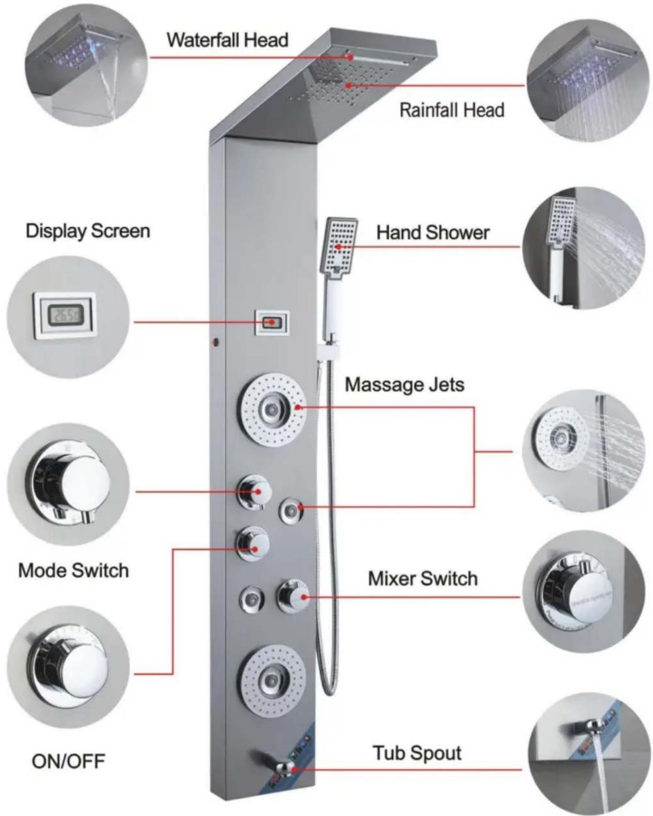
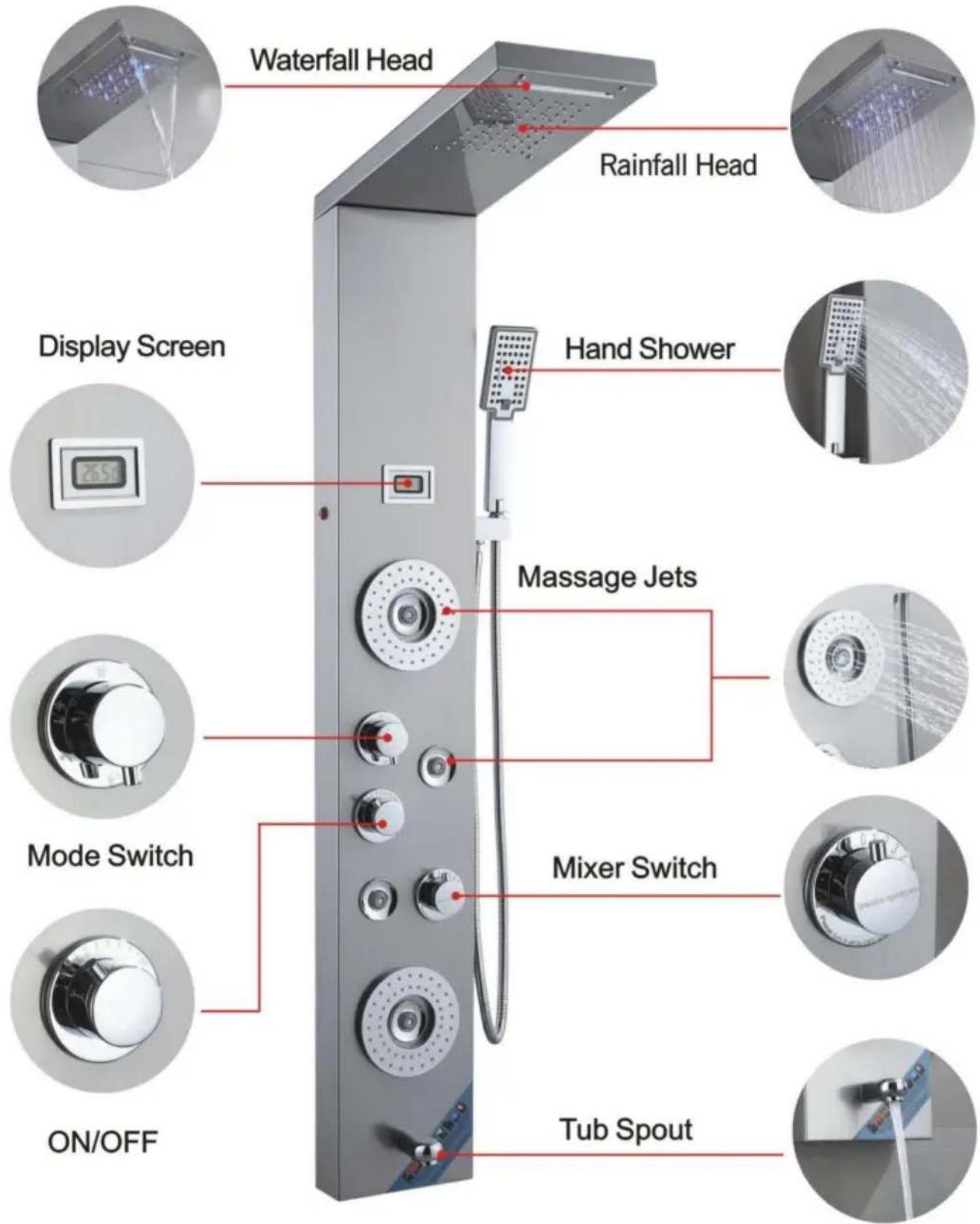
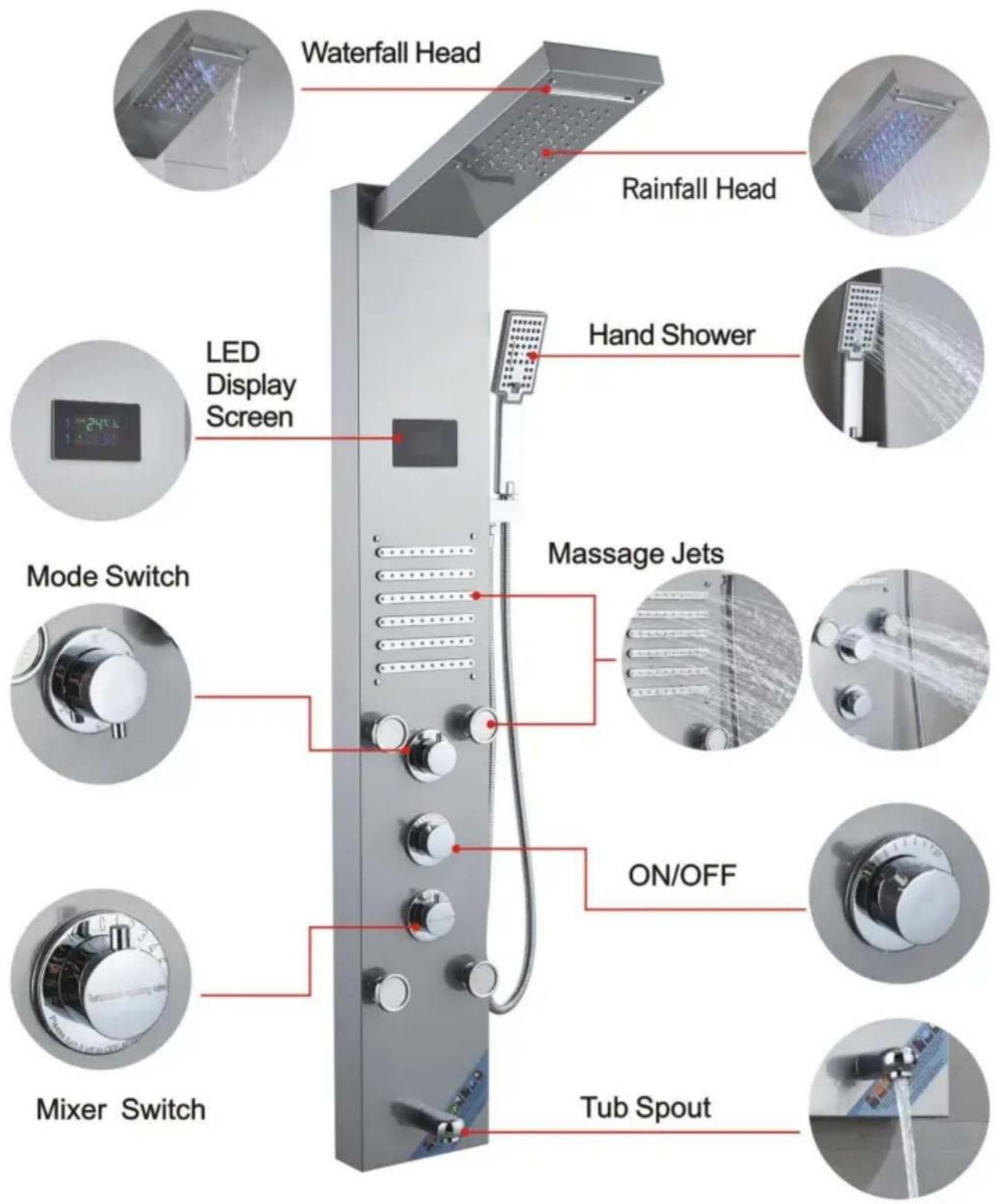
8039FLWaterfall Head, Rainfall Head, Display Screen, Hand Shower, Massage Jets, Mode Switch, Mixer Switch, ON/OFF, Tub Spout.

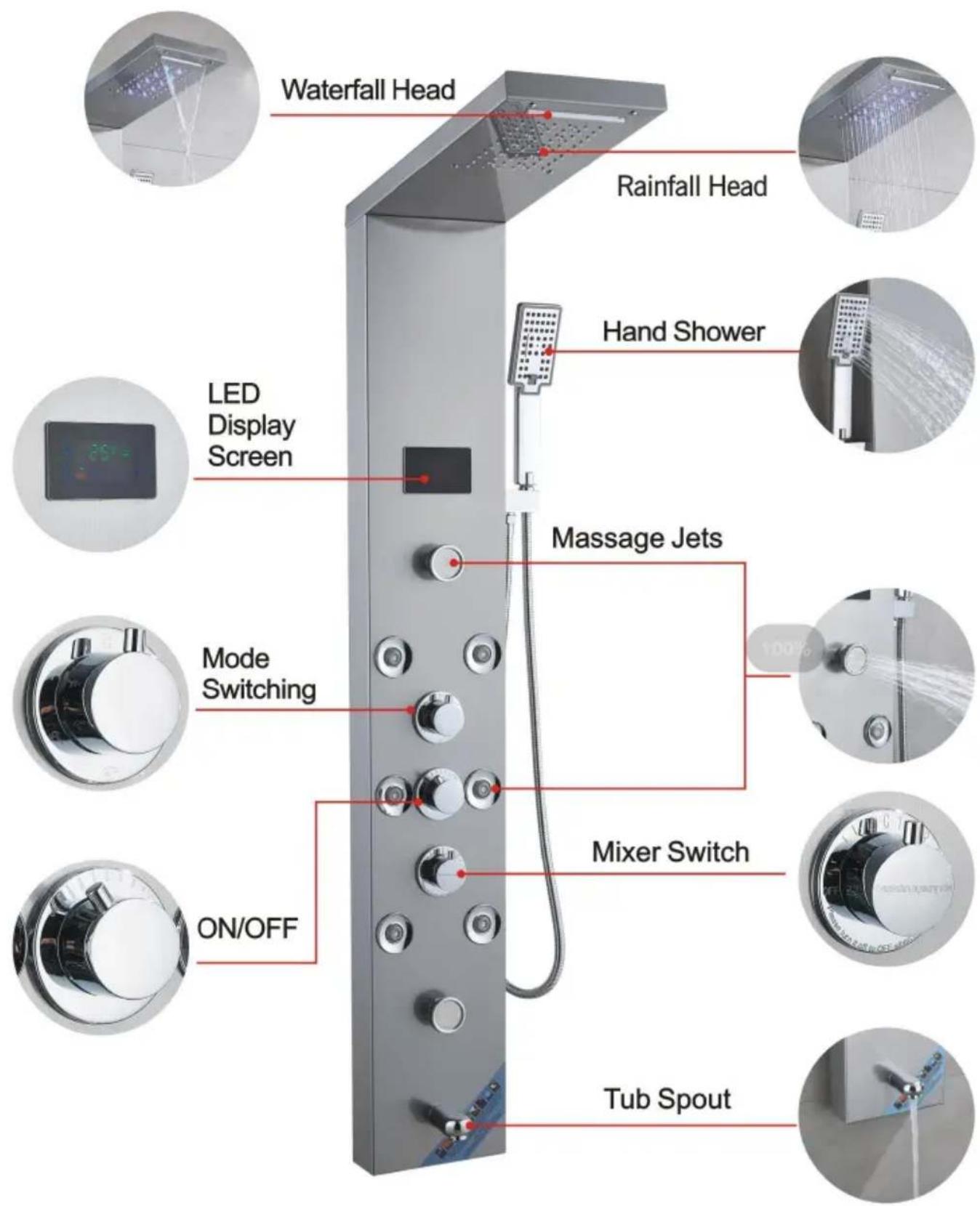
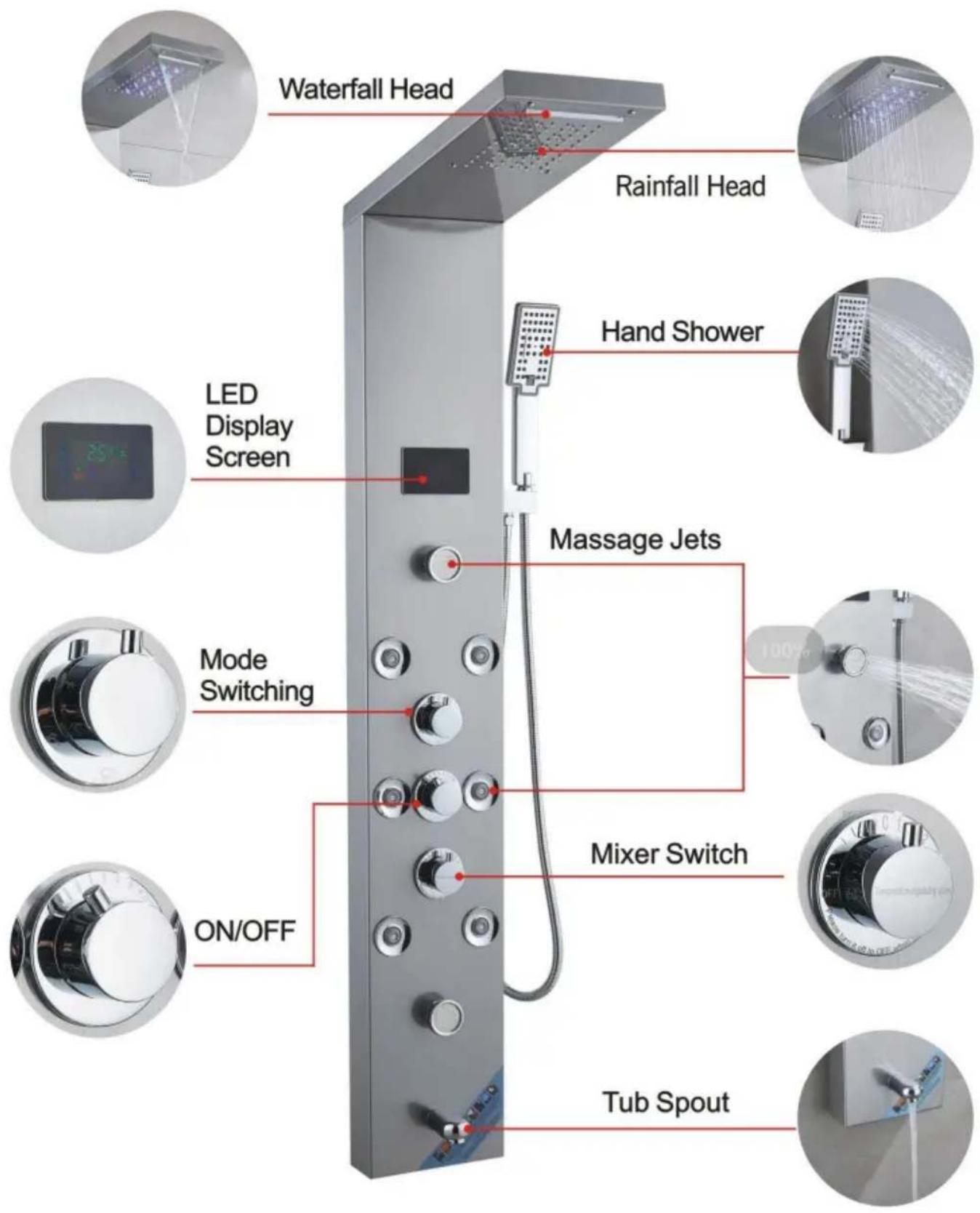
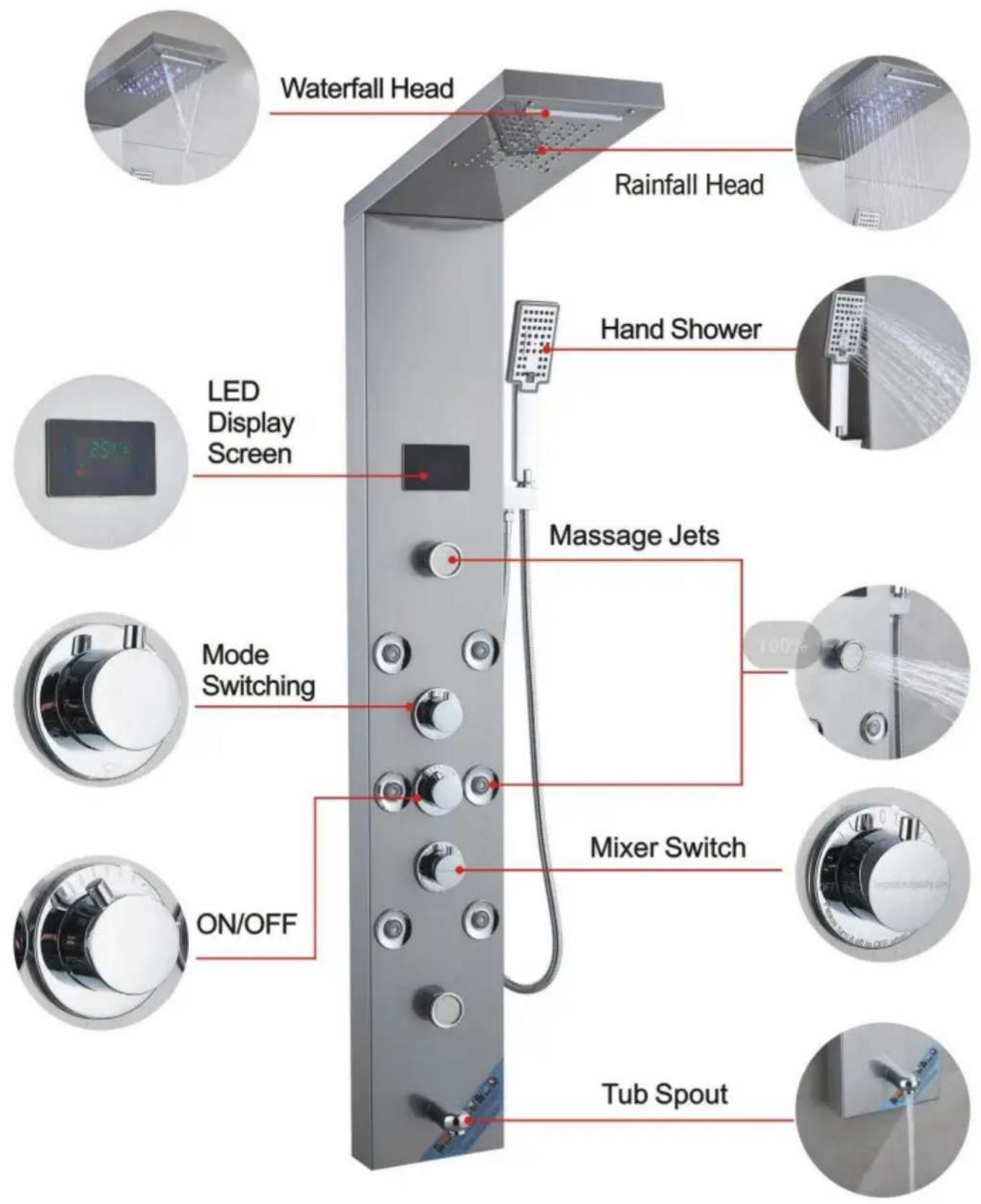
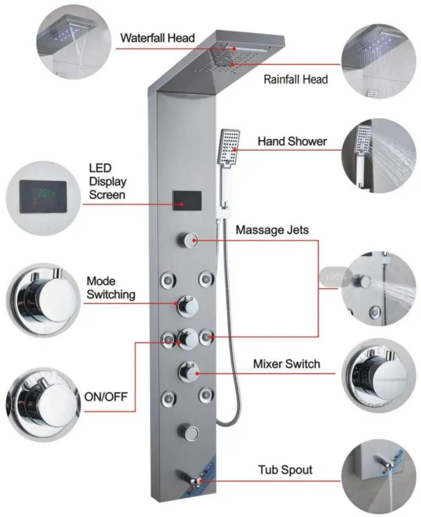
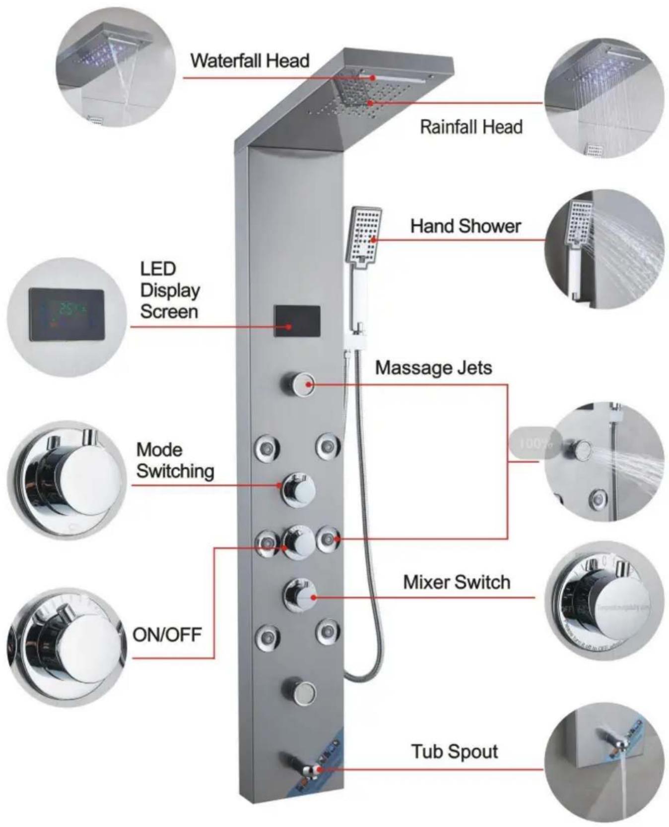
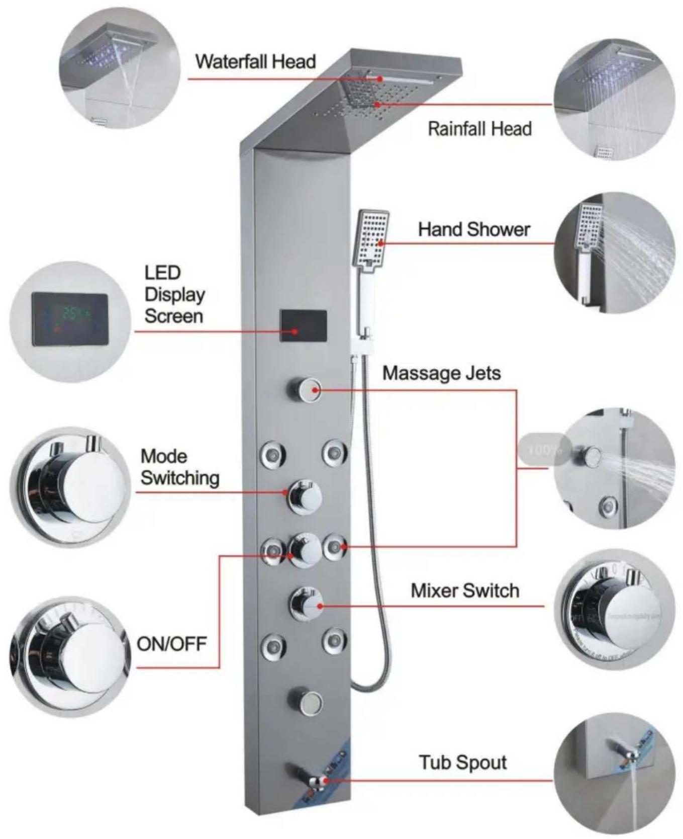
8009FLWaterfall Head, Rainfall Head, Hand Shower, LED Display Screen, Massage Jets, Mode Switching, ON/OFF, Mixer Switch, Tub Spout.

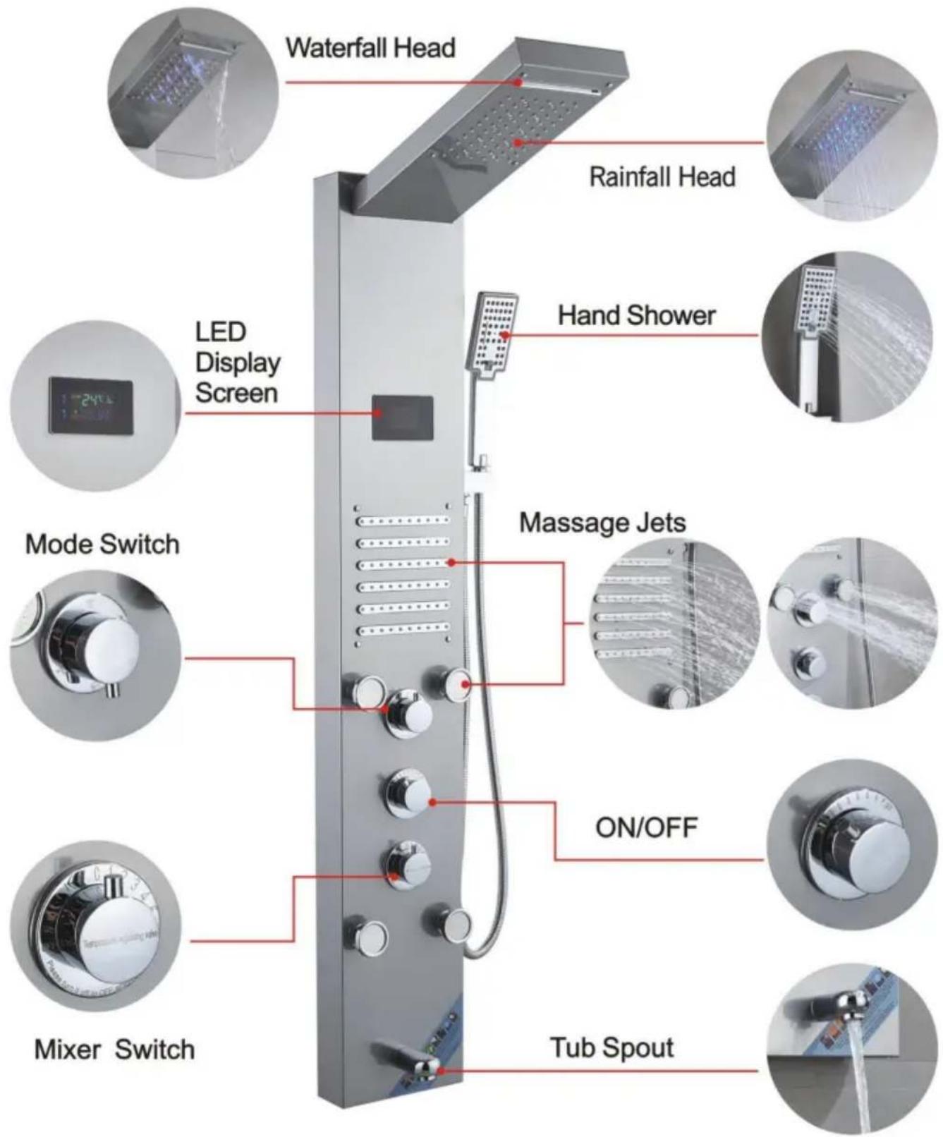
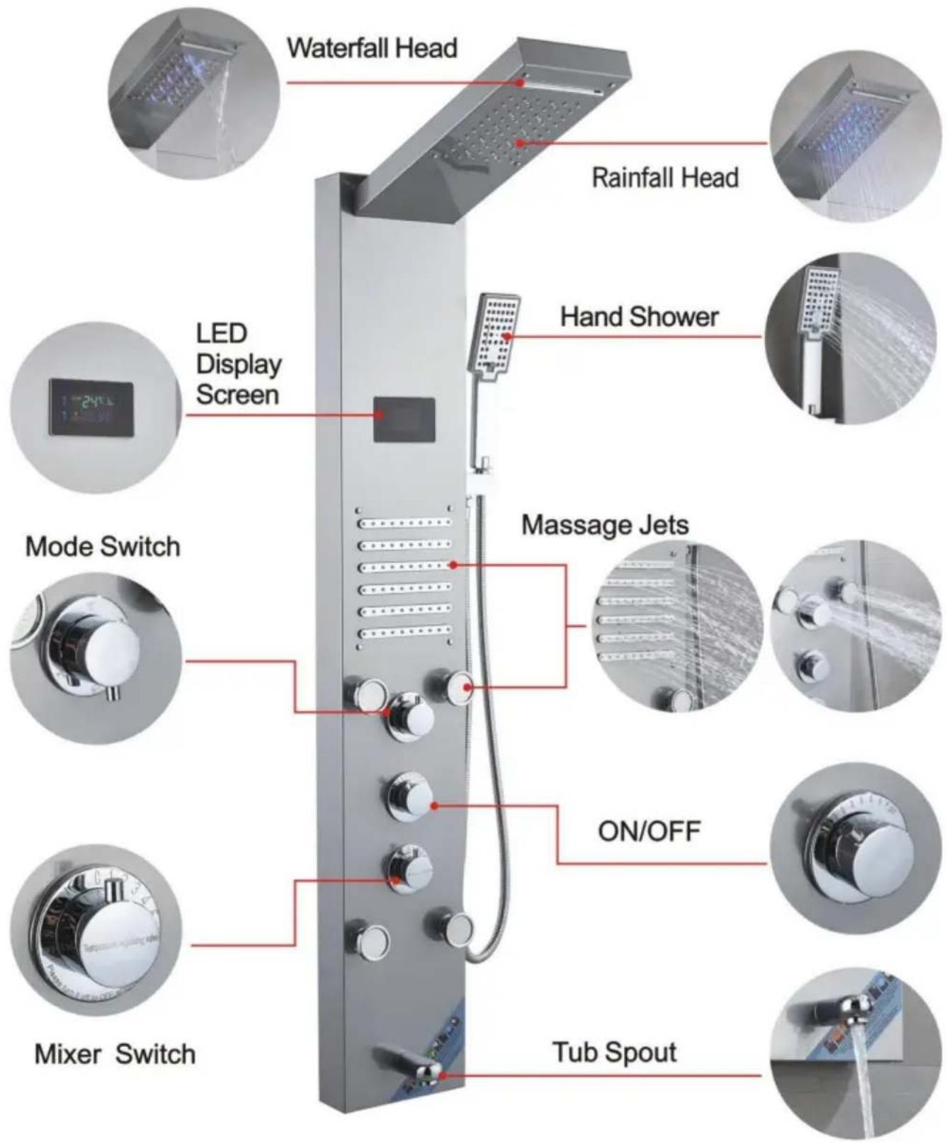
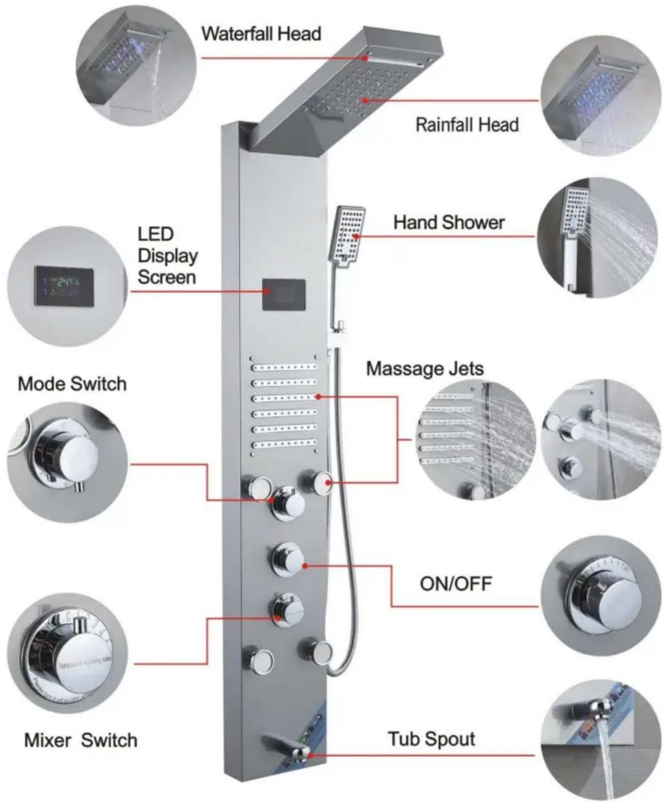
8004FLWaterfall Head, Rainfall Head, LED Display Screen, Hand Shower, Massage Jets, Mode Switch, ON/OFF, Mixer Switch, Tub Spout.

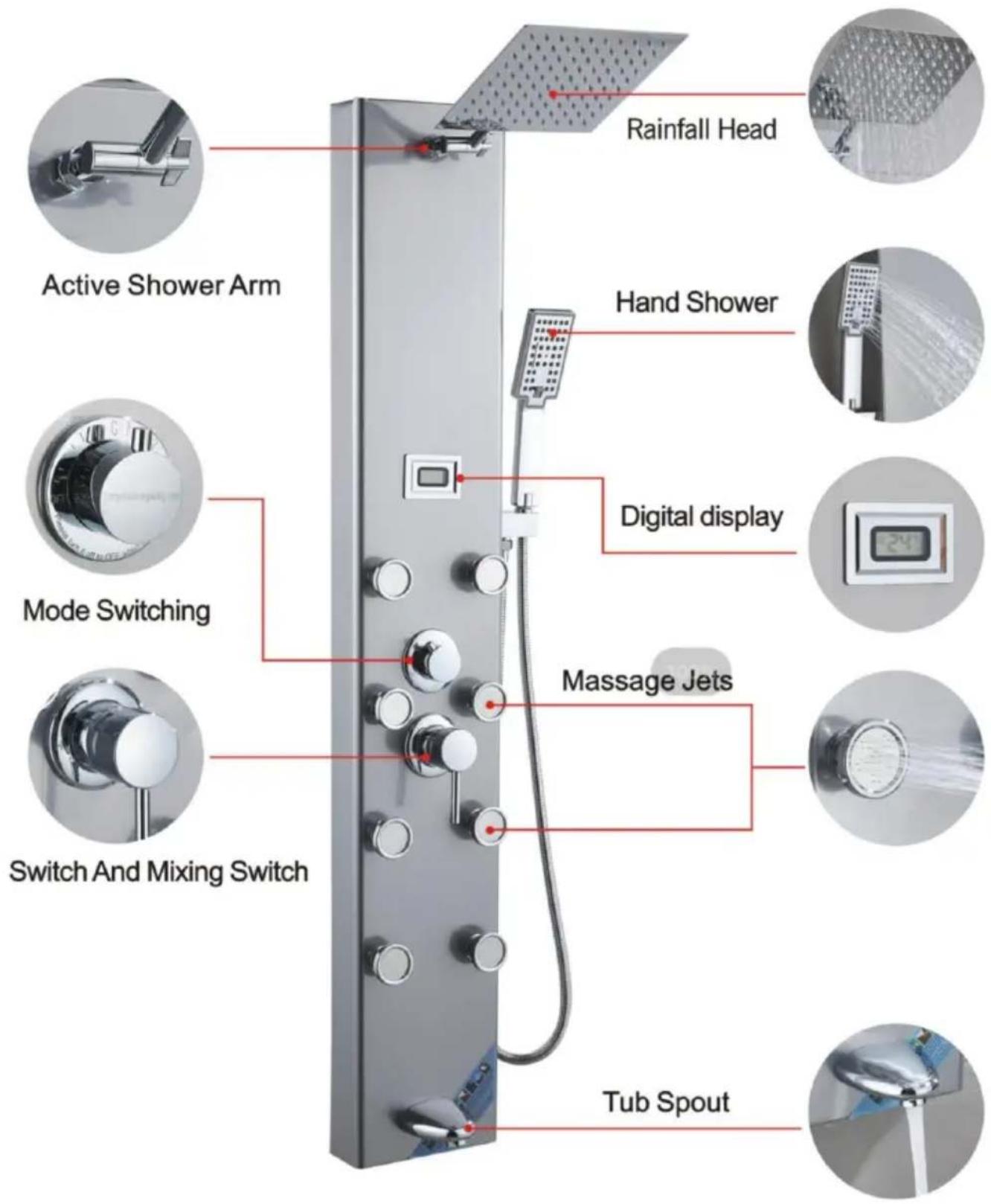
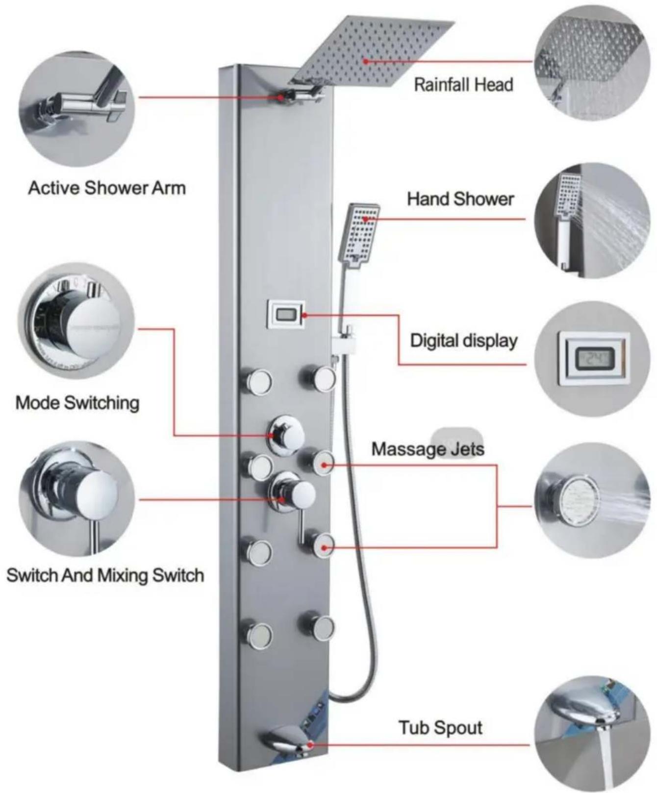
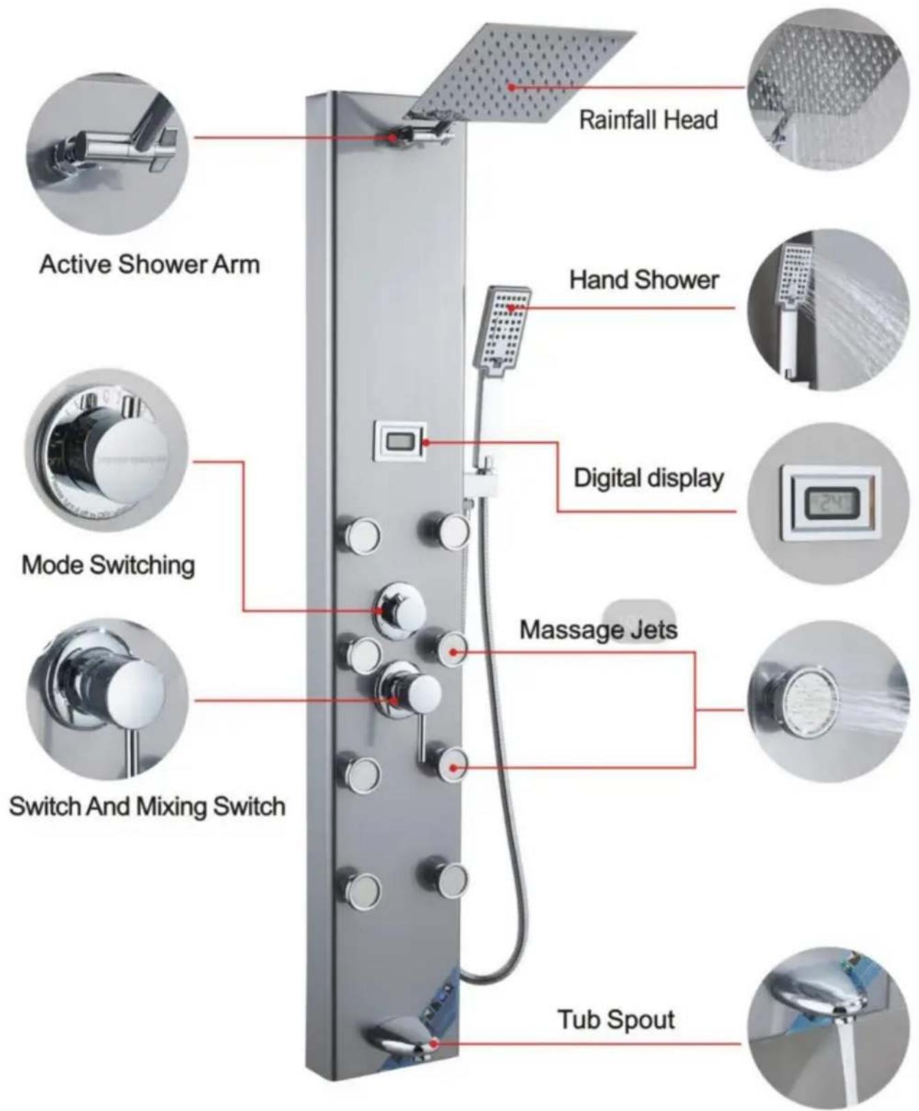
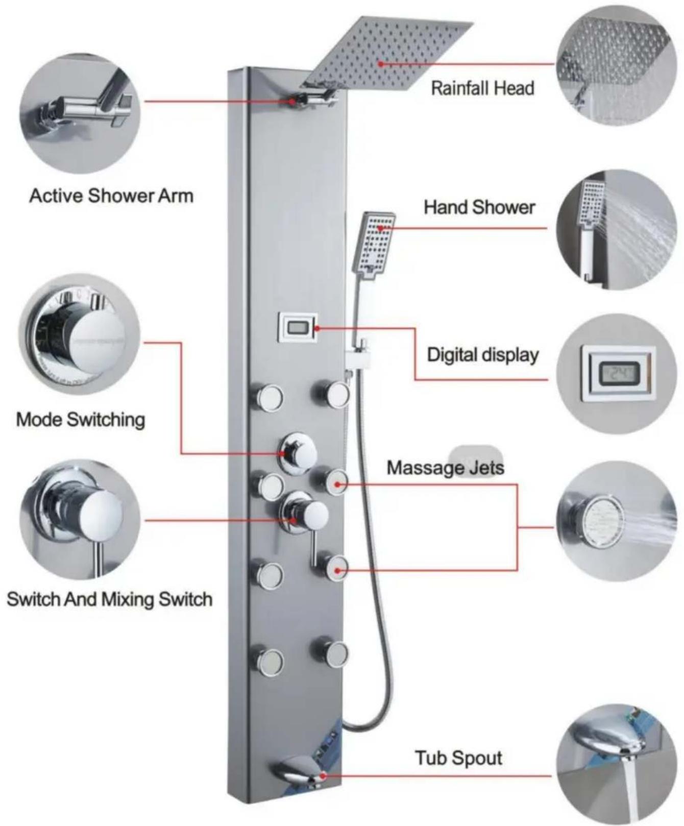
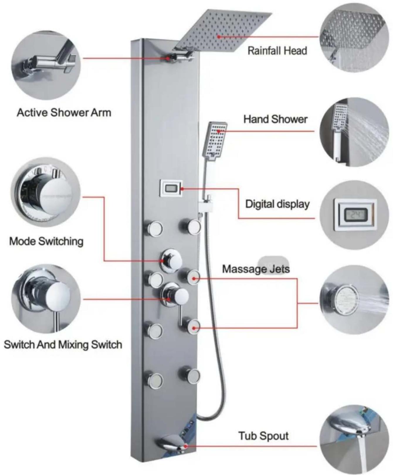
7009FLActive Shower Arm, Mode Switching, Switch And Mixing Switch, Tub Spout, Rainfall Head, Hand Shower, Digital display, Massage Jets.

Made In China

VEVOR®

TOUGH TOOLS, HALF PRICE

Technical Support and E-Warranty Certificate

www.vevor.com/support

VEVOR®

TOUGH TOOLS, HALF PRICE

Insert the PVC pipe from the top opening to pierce out.

Close-up of a hand holding a metallic device with visible wiring and components (no text or symbols).

Route the LED light wire along the hole and insert it into the motherboard.

Close-up of a metallic mechanical component with a rectangular cutout and bolted joints (no visible text or symbols).

Fix the motherboard and top spray with 4 pairs of M6 screws and nuts.

Close-up of industrial equipment with coiled cables and a numbered label (4) in the corner, no readable text or symbols on the cables themselves.

Fix the PVC pipe with a throat clamp on the top spray joint.

Close-up of a hand holding a black cable with a red connector, next to a white appliance (no visible text or symbols)

Connect the LED light cable and power supply line.

Person in gloves installing or adjusting electrical wiring inside a device (no visible text or symbols)

Install 2 No. 5 batteries to charge the pool box.

Close-up of hands holding a black electronic component with red wires, next to mechanical parts (no visible text or symbols)

Point the switch of the battery box towards ON.

Close-up of a metallic connector with red cable and blue plastic wrap, no visible text or symbols

Insert the hand spray nozzle into the panel and install the gasket.

Close-up of a metallic industrial electrical panel with visible wiring and connectors (no text or symbols)

Spray socket with hexagonal nut handle fixed on the panel.

Close-up of a hand holding a hexagonal connector component, no visible text or symbols

Put the 4-point rubber into the hand spray inside the joint of the seat.

11 circles

Connect the water outlet connector and hand spray seat joint.

Close-up of a black industrial cabinet or enclosure with a coiled spring, no visible text or symbols

Connect the hand spray hose to the handheld shower head.

MODEL 8004FL

Interior view of a stainless steel kitchen appliance with a door and side panel (no visible text or symbols)

Insert the top spray into the motherboard inside the hole.

Person in gloves operating a control panel with wires and components (no visible text or symbols)

Use 2 M4 screws to secure the main fixed plate and top spray.

Interior view of a laboratory or lab apparatus with a curved tube and two small objects on a beige surface, labeled with number 3 (no readable text or symbols)

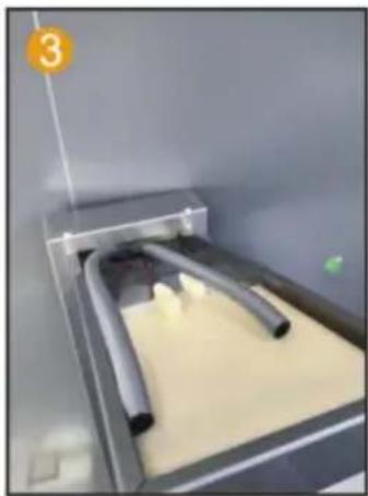
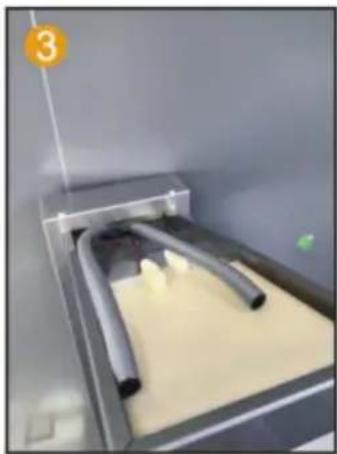
Connect PVC pipes and LED light wires, thread through the hole.

Person in gloves handling a white plastic component inside a metal enclosure (no visible text or symbols)

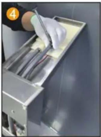
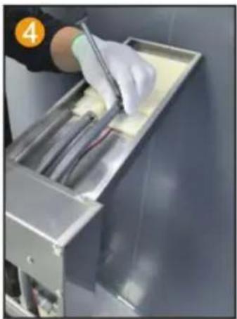
Fix the PVC pipe with a throat clamp on the top spray joint.

Close-up of gloved hands installing or adjusting a black cable with red wire, no visible text or symbols

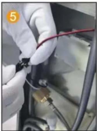
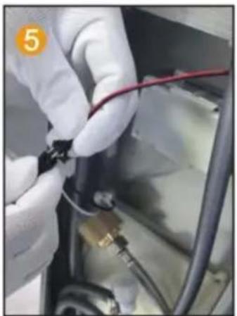
Connect the LED light cable and power supply line.

Close-up of a black plastic connector with red cable and orange number 6 (no visible text or symbols)

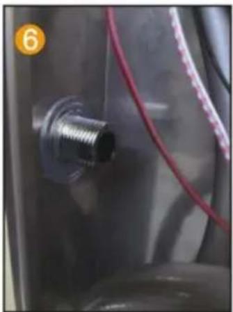
Insert the hand spray nozzle into the panel and install the gasket.

Close-up of industrial equipment with metal components and wiring (no visible text or symbols)

Spray socket with hexagonal nut handle fixed on the panel.

Close-up of a gloved hand inserting a small component into a device panel (no visible text or symbols)

Spray socket with hexagonal nut handle, fix the 4-point rubber on the panel and spray it by hand inside the joint of the seat.

Person in gloves handling a device inside a stainless steel enclosure (no visible text or symbols)

Connect the water outlet connector and hand spray seat joint.

Person in gloves operating industrial machinery with visible wiring and components (no text or symbols)

Connect the hand spray hose to the handheld shower head.

MODEL 7009FLFix the water outlet arm on the motherboard

Connect the top spray and outlet arm joints

Install 2 No. 5 batteries into the battery box

Turn the switch of the battery box to ON

Insert the hand spray nozzle into the panel and install the gasket

Spray socket with hexagonal nut handle fixed on the panel

Put the 4-cent eraser inside the joint of the hand spray seat

Connect the water outlet connector and hand spray seat joint

Connect the hand spray hose to the handheld showerhead

INSTALLATION STEPS (GENERAL)

First measure the distance between the shower screen and the trough, then use a marker to fix the location of the marker

Wall drilling depth of about 40mm. Use an electric drill to mark the hole

3 First with a hammer will be inflated Screw into the wall With a screwdriver Fix the screw

4 Wall Fastener Fastener Hot and cold water outlet First turn the elbow and the wall pipe connected respectively. And then the hot and cold water pipes and elbows can be connected

5 Hang the shower panel on the fasteners

INTRODUCTION OF FUNCTIONS

8015FLWaterfall Head, Rainfall Head, Hand Shower, Rainfall Switch, Waterfall Switch, Handshower Switch, Massage Jets, Massage Jets Switch, Switch and Mixer switch

INTRODUCTION OF FUNCTIONS

6002FLWaterfall Head, Rainfall Head, LED Light Switch, Hand Shower, Mode Switching, Massage Jets, Switch And Mixing Switch, Tub Spout

INTRODUCTION OF FUNCTIONS

8039FLWaterfall Head, Rainfall Head, Display Screen, Hand Shower, Massage Jets, Mode Switch, Mixer Switch, ON/OFF, Tub Spout

INTRODUCTION OF FUNCTIONS

8009FLWaterfall Head, Rainfall Head, Hand Shower, LED Display Screen, Massage Jets, Mode Switching, ON/OFF, Mixer Switch, Tub Spout

INTRODUCTION OF FUNCTIONS

8004FLWaterfall Head, Rainfall Head, LED Display Screen, Hand Shower, Mode Switch, Massage Jets, ON/OFF, Mixer Switch, Tub Spout

INTRODUCTION OF FUNCTIONS

7009FLActive Shower Arm, Mode Switching, Switch And Mixing Switch, Tub Spout, Rainfall Head, Hand Shower, Digital display, Massage Jets

Made in China

VEVOR®

TOUGH TOOLS, HALF PRICE

MODEL: 8015FL/6002FL/8039FL/8009FL/8004FL/7009FL

Insert the PVC pipe from the top opening to pierce out.

Close-up of a hand holding a metallic device with visible wiring and components (no text or symbols)

Route the LED light wire along the hole and insert into the motherboard.

Close-up of a metallic mechanical component with a rectangular cutout and bolted joints (no visible text or symbols)

Fix the motherboard and top spray with 4 pairs of M6 screws and nuts.

Close-up of industrial equipment with coiled cables and a numbered label (4) in the corner, no readable text or symbols on the cables themselves.

Fix the PVC pipe with a throat clamp on the top spray joint.

Close-up of a hand holding a black cable with a red connector, next to a white appliance (no visible text or symbols)

Connect the LED light cable and power supply line.

Person in gloves installing or adjusting electrical wiring inside a device (no visible text or symbols)

Install 2 No. 5 batteries to charge the pool box.

Close-up of hands holding a black electronic component with red wires, next to mechanical parts (no visible text or symbols)

Point the switch of the battery box towards ON.

Close-up of a metallic connector with red cable and blue plastic wrap, no visible text or symbols

Insert the hand spray nozzle into the panel and install the gasket.

Close-up of industrial equipment with white cables and wiring, no visible text or symbols

Spray socket with hexagonal nut handle fixed on the panel.

Close-up of a hand holding a hexagonal connector component, no visible text or symbols

Put the 4-point rubber into the hand spray inside the joint of the seat.

11 circles

Connect the water outlet connector and hand spray seat joint.

Close-up of a black industrial cabinet or enclosure with a coiled spring, no visible text or symbols

Connect the hand spray hose to the handheld one shower head.

MODEL 8004FL

Interior view of a stainless steel kitchen appliance with a door and side panel (no visible text or symbols)

Insert the top spray into the motherboard inside the hole.

Person in cleanroom gloves handling a device with wires and components (no visible text or symbols)

Use 2 M4 screws to secure the main fixed plate and top spray.

Interior view of a laboratory or lab apparatus with a curved tube and two small objects on a beige surface, labeled with number 3 (no readable text or symbols)

Connect PVC pipes and LED light wires, threading them through the hole.

Person in gloves handling a white plastic component inside a metal enclosure (no visible text or symbols)

Fix the PVC pipe with a throat clamp on the top spray joint.

Close-up of gloved hands installing or adjusting a black cable with red wire, no visible text or symbols

Connect the LED light cable and power supply line.

Close-up of a mechanical component with a threaded fitting and red cable, no visible text or symbols

Insert the hand spray nozzle into the panel and install the gasket.

Close-up of industrial equipment with metal components and wiring (no visible text or symbols)

Spray socket with hexagonal nut handle, fixed on the panel.

Close-up of a gloved hand inserting a small component into a device (no visible text or symbols)

Spray socket with hexagonal nut handle, fix the 4-point rubber on the panel and spray it by hand inside the joint of the seat.

Person in gloves handling a device inside a stainless steel enclosure (no visible text or symbols)

Connect the water outlet connector and hand spray seat joint.

Person in gloves operating industrial machinery with visible wiring and components (no text or symbols)

Connect the hand spray hose to the handheld shower head.

MODELL 7009FL

Fix the water outlet arm on the motherboard

2. Connect the top spray and outlet arm joints

Install 2 No. 5 batteries into the battery box

Turn the switch of the battery box to ON

5. Insert the hand spray nozzle into the panel and install the gasket

Spray socket with hexagonal nut handle fixed on the panel

7. Put the 4-cent eraser inside the joint of the hand spray seat

8. Connect the water outlet connector and hand spray seat joint

Connect the hand spray hose to the handheld showerhead

INSTALLATION STEPS (GENERAL)

Vevor 8039FL - INSTALLATION STEPS (GENERAL) - 1

Installation instructions

INSTALLATION DIAGRAM OF THE SHOWER PANEL SERIES

First, measure the distance between the top and bottom of the shower screen trough, then use a marker to fix the location of the marker

2. Wall. Drilling depth of about 40mm. With an electric drill, mark the hole

3. First, with a hammer, inflate the screw into the wall. With a screwdriver, fix the screw

4. Wall. Fastener. Fastener. Hot and cold water outlet. First, turn the elbow and the wall pipe connected respectively. And then the hot and cold water pipes and elbows can be connected

5. Hang the shower panel on the fasteners

FUNCTION INTRODUCTION

8015FLWaterfall Head, Rainfall Head, Hand Shower, Rainfall Switch, Waterfall Switch, Handshower Switch, Massage Jets, Massage Jets Switch, Switch and Mixer switch

FUNCTION INTRODUCTION

6002FLWaterfall Head, Rainfall Head, LED Light Switch, Hand Shower, Mode Switching, Massage Jets, Switch And Mixing Switch, Tub Spout

FUNCTION INTRODUCTION

8039FLWaterfall Head, Rainfall Head, Display Screen, Hand Shower, Massage Jets, Mode Switch, Mixer Switch, ON/OFF, Tub Spout

FUNCTION INTRODUCTION

8009FLWaterfall Head, Rainfall Head, Hand Shower, LED Display Screen, Massage Jets, Mode Switching, ON/OFF, Mixer Switch, Tub Spout

FUNCTION INTRODUCTION

8004FLWaterfall Head, Rainfall Head, LED Display Screen, Hand Shower, Mode Switch, Massage Jets, ON/OFF, Mixer Switch, Tub Spout

FUNCTION INTRODUCTION

7009FLRainfall Head, Active Shower Arm, Hand Shower, Digital display, Mode Switching, Massage Jets, Switch And Mixing Switch, Tub Spout

www.vevor.com/support

VEVOR®

TOUGH TOOLS, HALF PRICE

Insert the PVC pipe from the top opening to pierce out.

Close-up of a hand holding a metallic device with visible wiring and components (no text or symbols)

Route the LED light wire along the hole and insert into the motherboard.

Close-up of a metallic mechanical component with a rectangular cutout and bolt holes (no visible text or symbols)

Fix the motherboard and top spray with 4 pairs of M6 screws and nuts.

Close-up of industrial equipment with coiled cables and a numbered label (4) in the corner, no readable text or symbols on the cables themselves.

Fix the PVC pipe with a throat clamp on the top spray joint.

Close-up of a hand holding a black cable with a red connector, next to a white appliance (no visible text or symbols)

Connect the LED light cable and power supply line.

Person in gloves installing or adjusting electrical wiring inside a device (no visible text or symbols)

Install 2 No. 5 batteries to charge the pool box.

Close-up of hands holding a black electronic component with red wires, next to mechanical parts (no visible text or symbols)

Point the switch of the battery box towards ON.

Close-up of a metallic connector with red cable and blue plastic wrap, no visible text or symbols

Insert the hand spray nozzle into the panel and install the gasket.

Close-up of industrial equipment with white cables and wiring, no visible text or symbols

Spray socket with hexagonal nut handle fixed on the panel.

Close-up of a hand holding a hexagonal connector component, no visible text or symbols.

Put the 4-point rubber into the hand spray inside the joint of the seat.

11 circles

Connect the water outlet connector and hand spray seat joint.

Close-up of a black industrial cabinet or enclosure with a coiled spring, no visible text or symbols.

2. Connect the top spray and outlet arm joints.

Install 2 No. 5 batteries into the battery box.

Turn the switch of the battery box to ON.

5. Insert the hand spray nozzle into the panel and install the gasket.

Spray socket with hexagonal nut handle fixed on the panel.
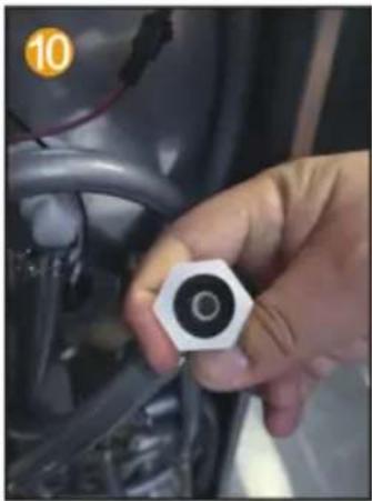
7. Put the 4-cent eraser inside the joint of the hand spray seat.

8. Connect the water outlet connector and hand spray seat joint.

Connect the hand spray hose to the handheld showerhead.

2. Wall drilling depth of about 40mm. With an electric drill, mark the hole.

3. First, with a hammer, inflate the screw into the wall. With a screwdriver, fix the screw.

4 Wall Fastener Fastener Hot and cold water outlet First turn the elbow and the wall pipe connected respectively. And then the hot and cold water pipes and elbows can be connected

5 Hang the shower panel on the fasteners

Insert the PVC pipe from the top opening to pierce out.

Close-up of a hand holding a metallic device with visible wiring and components (no text or symbols)

Route the LED light wire along the hole and insert it into the motherboard.

Close-up of a metallic mechanical component with a rectangular cutout and bolted joints (no visible text or symbols)

Fix the motherboard and top spray with 4 pairs of M6 screws and nuts.

Close-up of industrial equipment with coiled cables and a numbered label (4) in the corner, no readable text or symbols on the cables themselves.

Fix the PVC pipe with a throat clamp on the top spray joint.

Close-up of a hand holding a black cable with a red connector, next to a white appliance (no visible text or symbols)

Connect the LED light cable and power supply line.

Person in gloves installing or adjusting electrical wiring inside a device (no visible text or symbols)

Install 2 No. 5 batteries to charge the pool box.

Close-up of hands holding a black electronic component with red wires, next to mechanical parts (no visible text or symbols)

Point the switch of the battery box towards ON.

Close-up of a metallic connector with red cable and cap, no visible text or symbols

Insert the hand spray nozzle into the panel and install the gasket.

Close-up of industrial equipment with white cables and wiring, no visible text or symbols.

Spray socket with hexagonal nut handle fixed on the panel.

Close-up of a hand holding a hexagonal connector component, no visible text or symbols.

Put the 4-point rubber into the hand spray inside the joint of the seat.
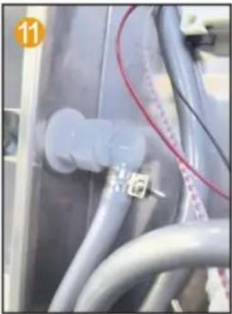
11 circles

Connect the water outlet connector and hand spray seat joint.
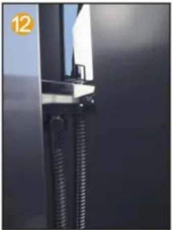
Close-up of a black industrial cabinet or enclosure with a coiled spring, no visible text or symbols.

Connect the hand spray hose to the handheld one shower head.

Interior view of a stainless steel kitchen appliance with a door and side panel, no visible text or symbols.

Insert the top spray into the motherboard inside the hole.

Person in cleanroom gloves handling a device with wires and components, no visible text or symbols.

Use 2 M4 screws to secure the main fixed plate and top spray.

Interior view of a laboratory or lab apparatus with a curved tube and two small objects on a beige surface, labeled with number 3, no readable text or symbols.

Connect PVC pipes and LED light wires, threading them through the hole.

Person in gloves handling a white plastic component inside a metal enclosure, no visible text or symbols.

Fix the PVC pipe with a throat clamp on the top spray joint.

Close-up of gloved hands installing or adjusting a cable with a red wire, no visible text or symbols.

Connect the LED light cable and power supply line.

Close-up of a black plastic connector with red cable and orange number 6, no visible text or symbols.

Insert the hand spray nozzle into the panel and install the gasket.

Close-up of industrial equipment with metal components and wiring, no visible text or symbols.

Spray socket with hexagonal nut handle, fixed on the panel.

Close-up of a gloved hand inserting a small component into a device, no visible text or symbols.

Spray socket with hexagonal nut handle, fix the 4-point rubber on the panel and spray it by hand inside the joint of the seat.

Person in gloves handling a device inside a stainless steel enclosure, no visible text or symbols.

Connect the water outlet connector and hand spray seat joint.

Person in gloves operating industrial machinery with visible wiring and components, no text or symbols.

Connect the hand spray hose to the handheld shower head.

Fix the water outlet arm on the motherboard.

2. Connect the top spray and outlet arm joints.

Install 2 No. 5 batteries into the battery box.

Turn the switch of the battery box to ON.

5. Insert the hand spray nozzle into the panel and install the gasket.

Spray socket with hexagonal nut handle fixed on the panel.

7. Put the 4-cent eraser inside the joint of the hand spray seat.

8. Connect the water outlet connector and hand spray seat joint.

Connect the hand spray hose to the handheld showerhead.

2. Wall: Drilling depth of about 40mm. With an electric drill, mark the hole.

3. First, with a hammer, will be inflated screw into the wall. With a screwdriver, fix the screw.

4. Wall: Fastener. Fastener. Hot and cold water outlet. First turn the elbow and the wall pipe connected respectively. And then the hot and cold water pipes and elbows can be connected.

5. Hang the shower panel on the fasteners.

Insert the PVC pipe from the top opening to pierce out.

Close-up of a hand holding a metallic device with visible wiring and components (no text or symbols)

Route the LED light wire along the hole and insert into the motherboard.

Close-up of a metallic mechanical component with a rectangular cutout and bolted joints (no visible text or symbols)

Fix the motherboard and top spray with 4 pairs of M6 screws and nuts.

Close-up of industrial equipment with coiled cables and a numbered label (4) in the corner, no readable text or symbols on the cables themselves.

Fix the PVC pipe with a throat clamp on the top spray joint.

Close-up of a hand holding a black cable with a red plug inserted, next to a white appliance (no visible text or symbols)

Connect the LED light cable and power supply line.

Person in gloves installing or adjusting electrical wiring inside a device (no visible text or symbols)

Install 2 No. 5 batteries to charge the pool box.

Close-up of hands holding a black electronic component with red wires, next to mechanical parts (no visible text or symbols)

Point the switch of the battery box towards ON.

Close-up of a metallic connector with red cable and blue plastic wrap, no visible text or symbols

Insert the hand spray nozzle into the panel and install the gasket.

Close-up of industrial equipment with white cables and wiring, no visible text or symbols

Spray socket with hexagonal nut handle fixed on the panel.

Close-up of a hand holding a hexagonal connector with a circular end, against a dark vehicle or car interior (no visible text or symbols)

Put the 4-point rubber into the hand spray inside the joint of the seat.

11 circles

Connect the water outlet connector and hand spray seat joint.

Close-up of a black industrial cabinet or enclosure with a coiled spring, no visible text or symbols

Connect the hand spray hose to the handheld shower head.

MODEL 8004FL
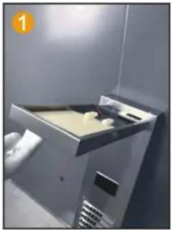
Interior view of a stainless steel kitchen appliance with a door and side panel.

Insert the top spray into the motherboard inside the hole.

Person in cleanroom gloves handling a device with wires and components.

Use 2 M4 screws to secure the main fixed plate and top spray.

Interior view of a laboratory apparatus with a curved tube and two small objects on a beige surface, labeled with number 3.

Connect PVC pipes and LED light wires thread through the hole.

Person in gloves handling a white plastic component inside a metal enclosure.

Fix the PVC pipe with a throat clamp on the top spray joint.

Close-up of gloved hands installing or adjusting a cable with a red wire.

Connect the LED light cable and power supply line.

Close-up of a black plastic connector with red cable and orange number 6.

Insert the hand spray nozzle into the panel and install the gasket.

Close-up of industrial equipment with metal components and wiring.

Spray socket with hexagonal nut handle, fixed on the panel.

Close-up of a gloved hand inserting a small component into a device panel.

Spray socket with hexagonal nut handle, fix the 4-point rubber on the panel and spray it by hand inside the joint of the seat.

Person in gloves handling a device inside a stainless steel enclosure.

Connect the water outlet connector and hand spray seat joint.

Person in gloves operating industrial machinery with visible wiring and components.

Connect the hand spray hose to the handheld shower head.

MODEL 7009FL

Fix the water outlet arm on the motherboard.

Connect the top spray and outlet arm joints.

Install 2 No. 5 batteries into the battery box.

Turn the switch of the battery box to ON.

Insert the hand spray nozzle into the panel and install the gasket.

Spray socket with hexagonal nut handle fixed on the panel.

7. Put the 4-centimeter eraser inside the joint of the hand spray seat.

8. Connect the water outlet connector and hand spray seat joint.

Connect the hand spray hose to the handheld showerhead.

INSTALLATION STEPS (GENERAL)

First, measure the distance between the top and bottom of the shower screen trough, then use a marker to fix the location of the marker.

2. Wall. Drilling depth of about 40mm. With an electric drill, mark the hole.

3. First, with a hammer, inflate the screw into the wall. With a screwdriver, fix the screw.

4. Wall. Fastener. Fastener. Hot and cold water outlet. First turn the elbow and the wall pipe connected respectively. And then the hot and cold water pipes and elbows can be connected.

5. Hang the shower panel on the fasteners.

FUNCTION INTRODUCTION

8015FLWaterfall Head, Rainfall Head, Hand Shower, Rainfall Switch, Waterfall Switch, Handshower Switch, Massage Jets, Massage Jets Switch, Switch and Mixer switch.

FUNCTION INTRODUCTION

6002FLWaterfall Head, Rainfall Head, LED Light Switch, Hand Shower, Mode Switching, Massage Jets, Switch And Mixing Switch, Tub Spout.

FUNCTION INTRODUCTION

8039FLWaterfall Head, Rainfall Head, Display Screen, Hand Shower, Massage Jets, Mode Switch, Mixer Switch, ON/OFF, Tub Spout.

FUNCTION INTRODUCTION

8009FLWaterfall Head, Rainfall Head, Hand Shower, LED Display Screen, Massage Jets, Mode Switching, ON/OFF, Mixer Switch, Tub Spout.

FUNCTION INTRODUCTION

8004FLWaterfall Head, Rainfall Head, LED Display Screen, Hand Shower, Mode Switch, Massage Jets, ON/OFF, Mixer Switch, Tub Spout.

FUNCTION INTRODUCTION

7009FLActive Shower Arm, Mode Switching, Switch And Mixing Switch, Tub Spout, Rainfall Head, Hand Shower, Digital display, Massage Jets.

www.vevor.com/support

VEVOR®

TOUGH TOOLS, HALF PRICE

Technical support and e-warranty certificate www.vevor.com/support

SHOWER PANEL TOWER

MODEL:8015FL/6002FL/8039FL/8009FL/8004FL/7009FL

NEED HELP? CONTACT US!

INSTALLATION INSTRUCTIONS

Model8015FL 6002FL 8039FL 8009FL 8004FL 7009FL
Montage TypeMuurMonterenMuurMonterenMuurMonterenMuurMonterenMuurMonterenMuurMonteren
Verbinding DraadG1/2"G1/2"G1/2"G1/2"G1/2"G1/2"
FunctiesVierModiVijfModiZesModiZesModiZesModiVijfModi
Baduitloop×ÿÿÿÿÿ
Temperatuur e Weergave××ÿÿÿÿ
LED lamp×ÿÿÿÿ×
Stroom×Droge cel (DC3V)Droge cel (DC3V)Hydro Stroom (AC6V)Hydro Stroom (AC6V)Droge cel (DC3V)
Hand Douche3-instellingen1-instellingen3-instellingen3-instellingen3-instellingen3-instellingen
FinishVingerafdrukvrij douchesysteem van geborsteld nikkel
MateriaalRoestvrij staal, messing, PVC, ABS

PARTS LIST

MODEL8015FL8039FL8009FL6002FL8004FL7009FL
M6 nutVevor 8039FL - PARTS LIST - 14pcs4pcs0pcs0pcs
M6 * 10 screwVevor 8039FL - PARTS LIST - 24pcs4pcs0pcs0pcs
Hose ClampVevor 8039FL - PARTS LIST - 32pcs2pcs2pcs0pcs
M4 * 10 screwVevor 8039FL - PARTS LIST - 40pcs0pcs2pcs0pcs
Brass shower armVevor 8039FL - PARTS LIST - 50pcs0pcs0pcs1pcs
Single function handheld showerVevor 8039FL - PARTS LIST - 60pcs1pcs0pcs0pcs
Panel cotton bagVevor 8039FL - PARTS LIST - 71pcs1pcs1pcs1pcs
Top spray cotton bagVevor 8039FL - PARTS LIST - 81pcs1pcs1pcs0pcs
Three function handheld showerVevor 8039FL - PARTS LIST - 91pcs0pcs1pcs1pcs
1.5 meter hand spray hoseVevor 8039FL - PARTS LIST - 101pcs1pcs1pcs1pcs
Hand spray seatVevor 8039FL - PARTS LIST - 111pcs1pcs1pcs1pcs
1/2 right angle adapterVevor 8039FL - PARTS LIST - 122pcs2pcs2pcs2pcs
4-point rubberVevor 8039FL - PARTS LIST - 132pcs2pcs2pcs2pcs
Self tapping screwVevor 8039FL - PARTS LIST - 144pcs4pcs4pcs4pcs
FastenerVevor 8039FL - PARTS LIST - 152pcs2pcs2pcs2pcs
GrommetVevor 8039FL - PARTS LIST - 161pcs1pcs1pcs1pcs
Hexagon nutVevor 8039FL - PARTS LIST - 171pcs1pcs1pcs1pcs

ASSEMBLY INSTRUCTIONS

MODEL8015FL/6002FL/8039FL/8009FL

Close-up of hands installing a cable or wire component on a wall, no text or symbols visible.

Insert the PVC pipe from the top opening to pierce out.

Close-up of a hand holding a metallic device with visible wiring and components, no text or symbols.

Route the LED light wire along the hole and insert into the motherboard.

Close-up of a metallic mechanical component with a rectangular cutout and bolted joints, no visible text or symbols.

Fix the motherboard and top spray with 4 pairs of M6 screws and nuts.

Close-up of industrial equipment with coiled cables and a numbered label (4) in the corner, no readable text or symbols on the cables themselves.

Fix the PVC pipe with a throat clamp on the top spray joint.

Close-up of a hand holding a black cable with a red connector, next to a white appliance, no visible text or symbols.

Connect the LED light cable and power supply line.

Person in gloves installing or adjusting electrical wiring inside a device, no visible text or symbols.

Install 2 No. 5 batteries to charge the pool box.

Close-up of hands holding a black electronic component with red wires, next to mechanical parts, no visible text or symbols.

Point the switch of the battery box towards ON.

Close-up of a metallic connector with red cable and blue plastic wrap, no visible text or symbols.

Insert the hand spray nozzle into the panel and install the gasket.

Close-up of industrial equipment with white cables and wiring, no visible text or symbols.

Spray socket with hexagonal nut handle fixed on the panel.

Close-up of a hand holding a hexagonal connector component, no visible text or symbols.

Put the 4-point rubber into the hand spray inside the joint of the seat.

11 圈

Connect the water outlet connector and hand spray seat joint.

Close-up of a black industrial cabinet or enclosure with a coiled spring, no visible text or symbols.

Connect the hand spray hose to the handheld one shower head.

MODEL 8004FL

Interior view of a stainless steel kitchen appliance with a door and side panel, no visible text or symbols.

Insert the top spray into the motherboard inside the hole.

Person in cleanroom gloves handling a device with wires and components, no visible text or symbols.

Use 2 M4 screws to secure the main fixed plate and top spray.

Interior view of a laboratory or lab apparatus with a curved tube and two small objects on a beige surface, labeled with number 3, no readable text or symbols.

Connect PVC pipes and LED light wires, threading them through the hole.

Person in gloves handling a white plastic component inside a metal enclosure (no visible text or symbols)

Fix the PVC pipe with a throat clamp on the top spray joint.

Close-up of gloved hands installing or adjusting a black cable with red wire, no visible text or symbols

Connect the LED light cable and power supply line.

Close-up of a mechanical component with a threaded fitting and red cable, no visible text or symbols

Insert the hand spray nozzle into the panel and install the gasket.

Close-up of industrial equipment with metal components and wiring (no visible text or symbols)

Spray socket with hexagonal nut handle, fixed on the panel.

Close-up of a gloved hand inserting a small component into a device (no visible text or symbols)

Spray socket with hexagonal nut handle, fix the 4-point rubber on the panel and spray it by hand inside the joint of the seat.

Person in gloves handling a device inside a stainless steel enclosure (no visible text or symbols)

Connect the water outlet connector and hand spray seat joint.

Person in gloves operating industrial machinery with visible wiring and components (no text or symbols)

Connect the hand spray hose to the handheld shower head.

MODEL 7009FL

Fix the water outlet arm on the motherboard

2. Connect the top spray and outlet arm joints

Install 2 No. 5 batteries into the battery box

Turn the switch of the battery box to ON

5. Insert the hand spray nozzle into the panel and install the gasket

Spray socket with hexagonal nut handle fixed on the panel

7. Put the 4-cent eraser inside the joint of the hand spray seat

8. Connect the water outlet connector and hand spray seat joint

Connect the hand spray hose to the handheld showerhead.

INSTALLATION STEPS (GENERAL)

Vevor 8039FL - INSTALLATION STEPS (GENERAL) - 1

USER MANUAL

2. Wall. Drilling depth of about 40mm. With an electric drill, mark the hole.

3. First with a hammer, the inflated screw will be screwed into the wall. With a screwdriver, fix the screw.

4. Wall. Fastener. Fastener. Hot and cold water outlet. First turn the elbow and the wall pipe connected respectively. And then the hot and cold water pipes and elbows can be connected.

5. Hang the shower panel on the fasteners.

FUNCTION INTRODUCTION

8015FLWaterfall Head, Rainfall Head, Hand Shower, Rainfall Switch, Waterfall Switch, Handshower Switch, Massage Jets, Massage Jets Switch, Switch and Mixer switch.

FUNCTION INTRODUCTION

6002FLWaterfall Head, Rainfall Head, LED Light Switch, Hand Shower, Mode Switching, Massage Jets, Switch And Mixing Switch, Tub Spout.

FUNCTION INTRODUCTION

8039FLWaterfall Head, Rainfall Head, Display Screen, Hand Shower, Massage Jets, Mode Switch, Mixer Switch, ON/OFF, Tub Spout.

FUNCTION INTRODUCTION

8009FLWaterfall Head, Rainfall Head, Hand Shower, LED Display Screen, Massage Jets, Mode Switching, ON/OFF, Mixer Switch, Tub Spout.

FUNCTION INTRODUCTION

8004FLWaterfall Head, Rainfall Head, LED Display Screen, Hand Shower, Mode Switch, Massage Jets, ON/OFF, Mixer Switch, Tub Spout.

FUNCTION INTRODUCTION

7009FLActive Shower Arm, Mode Switching, Switch And Mixing Switch, Tub Spout, Rainfall Head, Hand Shower, Digital display, Massage Jets.

Made in China

VEVOR®

TOUGH TOOLS, HALF PRICE

warranty certificate www.vevor.com/support

VEVOR®

TOUGH TOOLS, HALF PRICE

MODEL:8015FL/6002FL/8039FL/8009FL/8004FL/7009FL

PRODUCT INTRODUCTION

Insert the PVC pipe from the top opening to pierce out

Close-up of a hand holding a metallic device with visible wiring and components (no text or symbols).

Route the LED light wire along the hole and insert into the motherboard

Close-up of a metallic mechanical component with a rectangular cutout and bolted joints (no visible text or symbols).

Fix the motherboard and top spray with 4 pairs of M6 screws and nuts

Close-up of industrial equipment with coiled cables and a numbered label (4) in the corner, no readable text or symbols on the cables themselves.

Fix the PVC pipe with a throat clamp on the top spray joint

Close-up of a hand holding a black cable with a red connector, next to a white appliance (no visible text or symbols).

Connect the LED light cable and power supply line

Person in gloves installing or adjusting electrical wiring inside a device (no visible text or symbols).

Install 2 No. 5 batteries to charge the pool box

Close-up of hands holding a black electronic component with red wires, next to mechanical parts (no visible text or symbols).

Point the switch of the battery box towards ON

Close-up of a metallic connector with red cable and cap, no visible text or symbols.

Insert the hand spray nozzle into the panel and install the gasket

Close-up of industrial equipment with white cables and wiring, no visible text or symbols.

Spray socket with hexagonal nut handle fixed on the panel

Close-up of a hand holding a hexagonal connector component, no visible text or symbols.

Put the 4-point rubber into the hand spray inside the joint of the seat

11 circles

Connect the water outlet connector and hand spray seat joint

Close-up of a black industrial cabinet or enclosure with a coiled spring, no visible text or symbols.

Connect the hand spray hose to the handheld shower head

MODEL 8004FL

Interior view of a stainless steel kitchen appliance with a door and side panel (no visible text or symbols).

Insert the top spray into the motherboard inside the hole
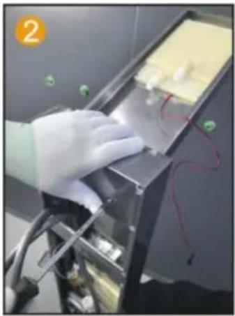
Person in cleanroom gloves handling a device with wires and components (no visible text or symbols).

Use 2 M4 screws to secure the main fixed plate and top spray.

Interior view of a laboratory or lab apparatus with a curved tube and two small objects on a beige surface, labeled with number 3 (no readable text or symbols).

Connect PVC pipes and LED light wires, threading them through the hole.

Person in gloves handling a white plastic component inside a metal enclosure (no visible text or symbols).

Fix the PVC pipe with a throat clamp on the top spray joint.

Close-up of gloved hands installing or adjusting a black cable with red wire, no visible text or symbols.

Connect the LED light cable and power supply line.

Close-up of a mechanical component with a threaded fitting and red cable, no visible text or symbols.

Insert the hand spray nozzle into the panel and install the gasket.

Close-up of industrial equipment with metal components and wiring (no visible text or symbols)

Spray socket with hexagonal nut handle, fixed on the panel.

Close-up of a gloved hand inserting a small component into a device (no visible text or symbols)

Spray socket with hexagonal nut handle, fix the 4-point rubber on the panel and spray it by hand inside the joint of the seat.

Person in gloves handling a device inside a stainless steel enclosure (no visible text or symbols)

Connect the water outlet connector and hand spray seat joint.

Person in gloves operating industrial machinery with visible wiring and components (no text or symbols)

Connect the hand spray hose to the handheld shower head.

MODELL 7009FL

Fix the water outlet arm on the motherboard

2. Connect the top spray and outlet arm joints

Install 2 No. 5 batteries into the battery box

Turn the switch of the battery box to ON

5. Insert the hand spray nozzle into the panel and install the gasket
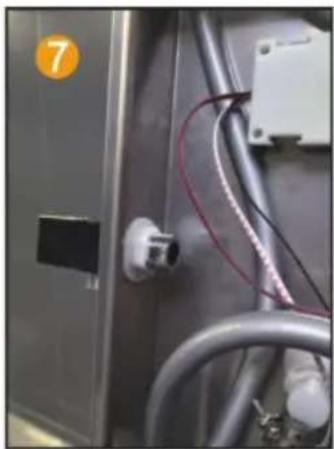
Spray socket with hexagonal nut handle fixed on the panel

7. Put the 4-cent eraser inside the joint of the hand spray seat

8. Connect the water outlet connector and hand spray seat joint

Connect the hand spray hose to the handheld showerhead

INSTALLATION STEPS (GENERAL)
First, measure the distance between the top and bottom of the shower screen trough, then use a marker to mark the location

2. Wall drilling depth of about 40mm. Use an electric drill to mark the hole

3. First, with a hammer, the screw will be inflated into the wall. With a screwdriver, fix the screw.

4. Wall, fastener, fastener, hot and cold water outlet. First turn the elbow and the wall pipe connected respectively. And then the hot and cold water pipes and elbows can be connected.

5. Hang the shower panel on the fasteners.

FUNCTION INTRODUCTION

8015FLWaterfall Head, Rainfall Head, Hand Shower, Rainfall Switch, Waterfall Switch, Handshower Switch, Massage Jets, Massage Jets Switch, Switch and Mixer switch.

FUNCTION INTRODUCTION

6002FLWaterfall Head, Rainfall Head, LED Light Switch, Hand Shower, Mode Switching, Massage Jets, Switch And Mixing Switch, Tub Spout.

FUNCTION INTRODUCTION

8039FLWaterfall Head, Rainfall Head, Display Screen, Hand Shower, Massage Jets, Mode Switch, Mixer Switch, ON/OFF, Tub Spout.

FUNCTION INTRODUCTION

8009FLWaterfall Head, Rainfall Head, Hand Shower, LED Display Screen, Massage Jets, Mode Switching, ON/OFF, Mixer Switch, Tub Spout.

FUNCTION INTRODUCTION

8004FLWaterfall Head, Rainfall Head, LED Display Screen, Hand Shower, Mode Switch, Massage Jets, ON/OFF, Mixer Switch, Tub Spout.

FUNCTION INTRODUCTION

7009FLActive Shower Arm, Mode Switching, Switch And Mixing Switch, Tub Spout, Rainfall Head, Hand Shower, Digital display, Massage Jets.

Made in China

VEVOR®

TOUGH TOOLS, HALF PRICE

www.vevor.com/support

Manual assistant
Powered by Anthropic
Waiting for your message
Product information

Brand : Vevor

Model : 8039FL

Category : Shower panel