EM4659A - Measuring equipment Vevor - Free user manual and instructions
Find the device manual for free EM4659A Vevor in PDF.

| Product Type | True RMS Auto-Ranging Digital Clamp Meter |
| Dimensions | 243 mm × 87 mm × 44 mm |
| Weight | Approx. 382 g (with batteries) |
| Power Supply | 3 AAA 1.5 V batteries |
| Display | 3 5/6-digit LCD with bargraph |
| Max Jaw Opening | Approx. 50 mm |
| Max Conductor Diameter | Approx. 38 mm |
| Safety Category | CAT III 1000 V, pollution degree 2 |
| Operating Temperature Range | 0°C to 40°C (humidity < 75%) |
| Protection Rating | IP20 |
| Measurement Functions | DC/AC voltage, DC/AC current, resistance, continuity, diode, capacitance, frequency, duty cycle, temperature (K-type thermocouple), inrush current, VFD voltage, VFD current, NCV detection |
| Special Functions | Data hold, relative mode, MIN/MAX, backlight, auto power off, low battery indicator, full range overload protection |
| Supplied Accessories | User manual, pair of test leads, K-type thermocouple |
| Warranty | 1 year against material and workmanship defects |
| Maintenance and Cleaning | Wipe with a damp cloth and mild detergent. Do not use abrasives or solvents. Clean the terminals with an alcohol-soaked swab. |
| Repairability | User replaceable batteries. For any other repairs, contact VEVOR after-sales service. |
Frequently Asked Questions - EM4659A Vevor
User questions about EM4659A Vevor
0 question about this device. Answer the ones you know or ask your own.
Ask a new question about this device
Download the instructions for your Measuring equipment in PDF format for free! Find your manual EM4659A - Vevor and take your electronic device back in hand. On this page are published all the documents necessary for the use of your device. EM4659A by Vevor.
USER MANUAL EM4659A Vevor
Technical Support and E-Warranty Certificate www.vevor.com/support
TRMS CLAMP MULTIMETER
USER MANUAL
MODEL:EM4659
We continue to be committed to provide you tools with competitive price. "Save Half", "Half Price" or any other similar expressions used by us only represents an estimate of savings you might benefit from buying certain tools with us compared to the major top brands and doses not necessarily mean to cover all categories of tools offered by us. You are kindly reminded to verify carefully when you are placing an order with us if you are actually saving half in comparison with the top major brands.
MODEL:EM4659
NEEDHELP?CONTACTUS!
Haveproductquestions?Needtechnicalsupport?Pleasefeelto contactus:

CustomerService@vevor.com
Thisistheoriginalinstruction,pleasereadallmanualinstructions carefullybeforeoperating.VEVORreservesaclearinterpretationofour usermanual.Theappearanceoftheproductshallbesubjecttothe productyoureceived.Pleaseforgiveusthatwewon'tinformyouagainif thereareanytechnologyorsoftwareupdatesonourproduct.
WARRANTY
This instrument is warranted to be free from defects in material and workmanship for a period of one year. Any instrument found defective within one year from the delivery date and returned to the factory with transportation charges prepaid, will be repaired, adjusted, or replaced at no charge to the original purchaser. This warranty does not cover expandable items such as battery. If the defect has been caused by a misuse or abnormal operating condition, the repair will be billed at a nominal cost.
INTRODUCTION
This instrument is a 52 digits true-RMS auto range digital clamp meter designed to measure DC and AC voltage, DC and AC current, resistance continuity, diode, capacitance, frequency, duty cycle, and temperature.
It features inrush current measurement, VFD voltage measurement, VFD current measurement, non-contact AC voltage detection, relative measurement, MIN MAX mode, data hold, bar graph, backlight, low battery indication, automatic power-off, illumination, full-range overload protection, etc. It is easy to operate and is a useful test tool
SAFETY INFORMATION
This meter has been designed according to IEC 61010 concerning electronic measuring instruments with a measurement category ( CAT III 1000V ) and Pollution Degree 2 .
To avoid possible electric shock or personal injury, follow these guidelines:
- Do not use the meter if it is damaged. Before you use the meter, inspect the case. Pay particular attention to the insulation surrounding the connectors.
- Inspect the test leads for damaged insulation or exposed metal. Check the test leads for continuity. Replace damaged test leads before you use the meter.
- Do not use the meter if it operates abnormally.
Protection may be impaired. When in doubt, have the meter serviced
- Do not operate the meter where explosive gas, vapor or dust is present.
- Do not apply more than the rated voltage, as marked on the meter, between terminals or between any terminal and earth ground.
- Before use, verify the meter's operation by measuring a known voltage.
- When servicing the meter, use only specified replacement parts.
- Use caution when working with voltage above 30V ac rms, 42V ac peak, or 60V dc. Such voltages pose a shock hazard.
- When using the probes, keep your fingers behind the finger guard on the probes.
- When making connections, connect the common test lead before you connect the live test lead. When you disconnect test leads, disconnect the live test lead first.
- Remove the test leads from the meter and the clamp from any conductor under test before you open the battery cover or the case.
- Do not operate the meter with the battery cover or portions of the cell removed or loosened.
- To avoid false readings, which could lead to possible electric shock or personal injury, replace the batteries as soon as the low battery
indicator ( ) appears.
- When in Relative mode or Data Hold mode or after zeroing the displa in DC current function, caution must be used because hazardous voltage may be present.
- Use the meter only as specified in this manual; otherwise the protection provided by the meter may be impaired.
- Adhere to local and national safety codes. Individual protective equipment must be used to prevent shock and arc blast injury where hazardous live conductors are exposed.
- To avoid electric shock and personal injury, do not touch any naked conductor with your hand or skin; and do not ground yourself while using this meter.
- Do not use the meter if the meter, a test lead or your hand is wet.
- Remaining endangerment: When an input terminal is connected to dangerous live potential, it is be noted that this potential can occur at all other terminals!
- Do not use the VFD voltage measurement function or VFD current measurement function to verify the presence of hazardous voltages or currents. Voltages or currents greater than what is indicated may be present.
- CAT III - Measurement Category III is for measurements performed in the building installation. Examples are measurements on distribution boards, circuit breakers, wiring, including cables, bus-bars, junction boxes, switches, socket-outlets in the fixed installation, and equipment for industrial use and some other equipment, for example, stationary motors with permanent connection to the fixed installation. Do not use the meter for measurements within Measurement Category IV.
Caution
To avoid possible damage to the meter or to the equipment und follow these guidelines:
- Disconnect circuit power and discharge all capacitors thoroughly before testing resistance, continuity, diode, capacitor, or temperature of an object.
- Use the proper terminals, function and range for your measurements.
- Before pressing a button to change function, disconnect the test leads and the clamp from any object under test.
Symbols
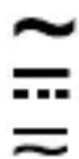
Alternating Current
Direct Current
DC or AC

Caution, risk of danger, refer to the operating manual before use.

Caution, risk of electric shock.
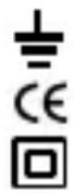
Earth ( ground ) Terminal
Conforms to European Union directives
The equipment is protected throughout by double insulation or reinforced insulation.

Application around and removal from hazardous live conductors is permitted.
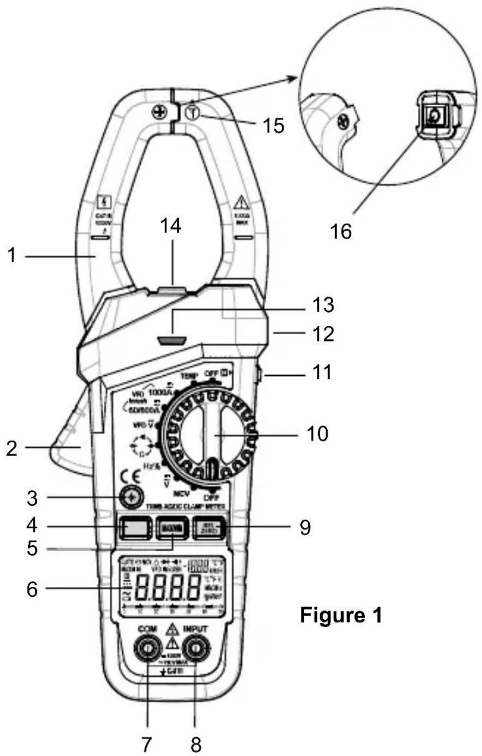
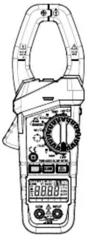
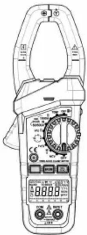
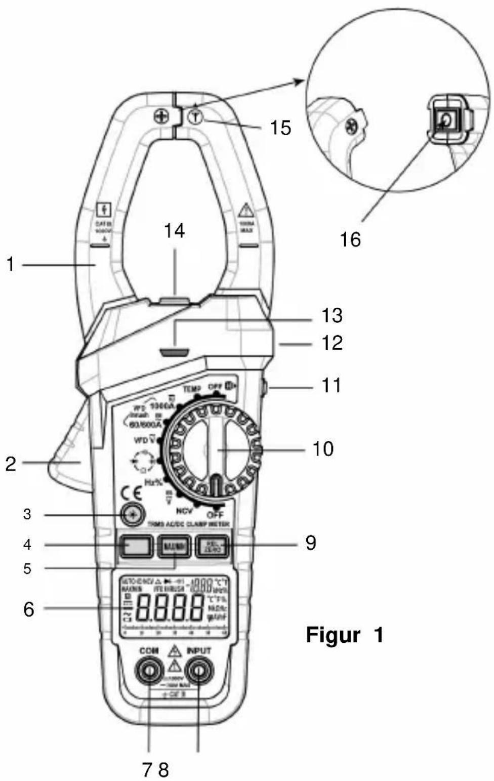
1.Jaws
Used for clamping the conductor for current measurements. The conductor should be positioned at the center of the jaws during measurement.
2.Trigger
Used to open and close the jaws.
3."Button
With the meter on, press this " - " button to turn on oroff the backlight. The backlight will turn off automaticallyafter about 30 secs.
4.FunctionSelectorButton
Used to switch between:
DC current, AC current, VFD current and inrush current measurement functions.
DC voltage and AC voltage measurement functions.
- Resistance, diode, continuity and capacitance test functions.
5." MAX/MIN "Button
Used to enter or exit the MIN MAX mode.
6.Display
3^5/6 digits LCD.
7."COM"Terminal
Plug-in connector for the black test lead.
8."INPUT"Terminal
Plug-in connector for the red test lead.
REL 9."Borlon
In dc current measurement function, press this "ZERO" button to zero the display before measurement. Press again to undo the zeroing.
In other measurement functions, this button is used to enter/exit Relative mode.
10.RotarySwitch
Used to select a desired function or range as well as to turn on or off the meter.
To save battery charge, set this rotary switch to " OFF " position to turn off the meter when the meter is not in use.
11. "Button
Briefly press this " H " button to enter or exit Data Holdmode. Press and hold down this button for about 2 secs to turn on or off the illumination LED
12.TactileBarrier
Used to prevent finger from touching the conductor under test. Do not hold the meter anywhere beyond the tactile barrier.
13.REDLED
An indicator used in non-contact ac voltage detection and continuity test.
14.IlluminationLED
15.NCVSensor
This NCV sensor is located at the mark " near the top of the clamp. It is used in non-contact ac voltage detection.
16. Jaw Wear Indicator
Warning:
To avoid injury, do not use the meter if the jaw wear indicator in the jaw opening is invisible.
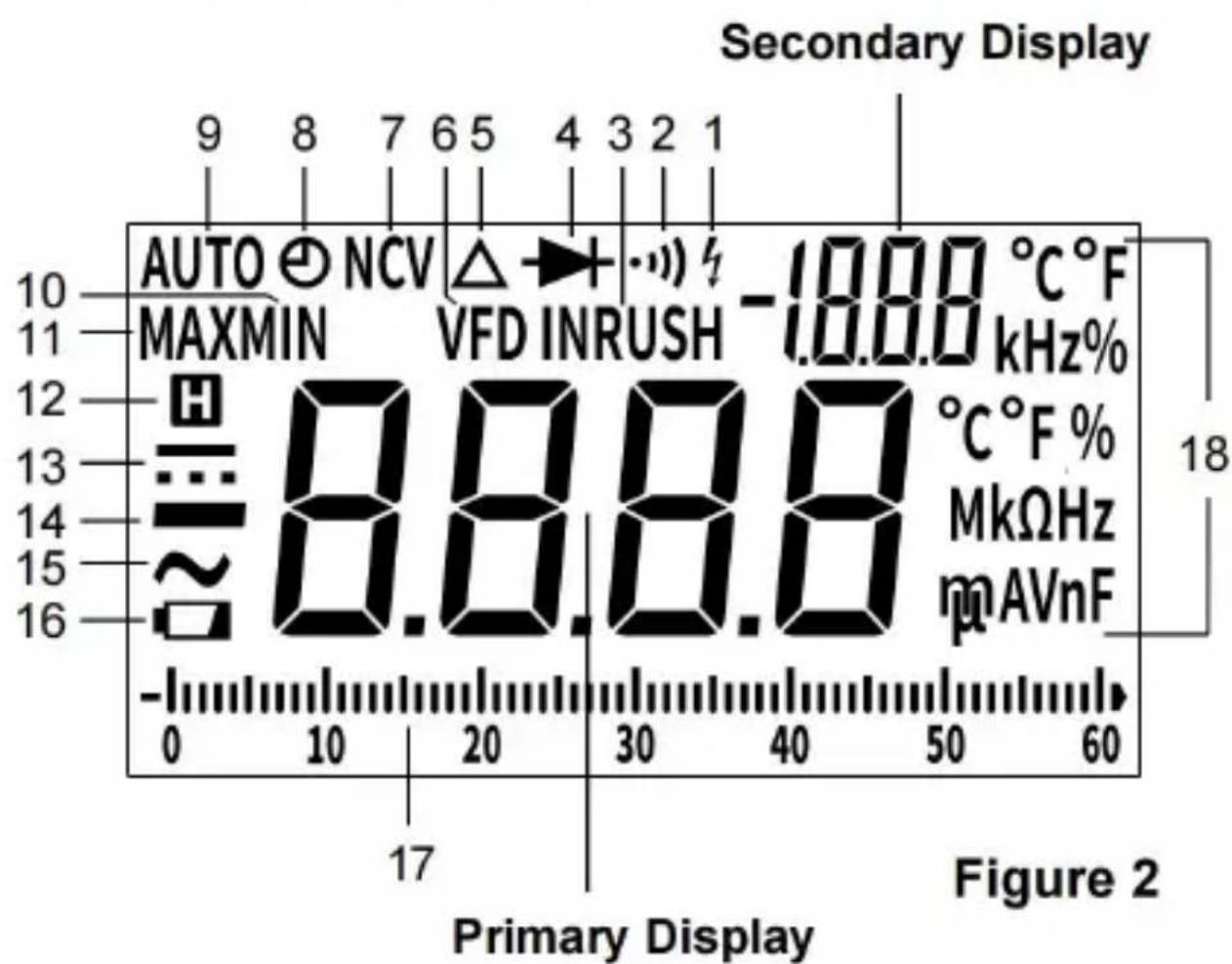
UNDERSTANDING THE DISPLAY
Symbol Meanings:
- The meter detects an input voltage >30V . This icon is intended to remind you that hazardous voltage is present and that you must use caution to avoid electric shock.
- Continuity test function is selected.
- INRUSH Inrush current measurement function is selected.
- Diode test function is selected.
- Relative mode is active.
- VFD variable frequency drive signal test is enabled.
- NCV Non-contact ac voltage detection function is selected.
- The automatic power-off feature is enabled.
- Autorange mode is active.
- MINMinimum reading is being displayed.
- MAX Maximum reading is being displayed.
-
- The meter is in Data Hold mode.
-
DC
-
Negative sign
- AC
- The batteries are low and must be replaced immediately.
17. Bar Graph
The bar graph on the top of the LCD is like the needle on an analog n It has an overload indicator( ) on its right and a negative polarity
indicator () on its left. The number of lit segments indicates the measured value and is relative to the full-scale value of the selected ran. In the 600V range, for example, the major divisions on the scale represe 0, 100, 200, 300, 400, 500 and 600V. An input of -100V lights the nega sign and the segments up to the " 10 " on the scale.
Note:
In frequency, duty cycle, temperature and capacitance measurement functions and non-contact ac voltage detection function, the bar graph is turned off.
18. Units:
| V | Unit of voltage V: Volt |
| A | Unit of current A: Ampere |
| Ω, kΩ, MΩ | Unit of resistance Ω: Ohm; kΩ: Kilohm; MΩ: Megohm 1MΩ = 3kΩ = 1Ω |
| nF, μF, mF | Unit of capacitance nF: Nanofarad; μF: Microfarad; mF: Millifarad 1mF = 1@pF = 10nF |
| Hz, kHz,MHz | Unit of frequency Hz: Hertz; kHz: Kilohertz; MHz: Megahertz 1MHz = 10kHz = 10Hz |
| °C, °F | Unit of temperature °C: Degree Celsius; °F: Degree Fahrenheit f (°F) = 32 + 1.8 x c (°C) |
| % | Unit of duty cycle %: Percent |
GENERAL SPECIFICATION
Display: 3^5/6 digits LCD
Negative Polarity Indication: Negative sign "-" shown on the display automatically
Sampling Rate: About 3 times/sec
Jaw Opening Capability: About 50mm
Max. Measurable Conductor for Current
Measurements: About 038mm
Low Battery Indication: " sown on the display
Battery: 1.5V battery, AAA or equivalent, 3 pieces
Operating Environment: Temperature: 0^ 40^
Relative Humidity: < 75%
Temperature Coefficient:
0.2 x (specified accuracy % ( < 18^ > 28^ )
Storage Environment: Temperature: -30^ 60^
Relative Humidity: < 85%
IP Degree: IP20
Operating Altitude: 0 to 2000 meters
Size: 243mm × 87mm × 44mm
Weight: About 382g (including battery)
SPECIFICATION
Accuracy is specified for a period of one year after calibration and at 18 to 28^ , with relative humidity < 75% .
Except for the ranges specified specially, accuracy is specified from 5% of range to 100% of range.
Accuracy specifications take the form of:
± ([% of Reading] +[number of Least Significant Digits])
DC Voltage
| Range Resolution | Resolution Accuracy | Overrange | Indication |
| 6V 0.001V | ± (0.8% + 5) " OL | " shown on the display | |
| 60V 0.01V | |||
| 600V 0. 1V | |||
| 1000V 1V ± (1.0% + 5) | ——[1] | ||
Input Impedance: 10MΩ
Max. Allowable Input Voltage: 1000V dc
Note:
- 1000V range is specified from 20% of range to 100% of range.
- When the input terminals are open, the display may show a reading other than zero. This is normal and will not affect measurements.
[1] If the voltage being measured is ≥ 1000V , the built-in buzzer will sound If the voltage is >1010V , the display will show "OL".
AC Voltage
| Range Resolution | Solution Accuracy | Overrange | Indication |
| 6V 0.001V | ± (0.8%)+ 5) | " OL " shown on the display | |
| 60V 0.01V | ± (1.2% + 5) | ||
| 600V 0. 1V | |||
| 750V 1V | [1] | ||
| VFD 750V | 1V | ± (2.5% + 15) | |
Input Impedance: 10MΩ
Frequency Range:
40Hz - 400Hz (only for 6V range)
40Hz - 1kHz ( only for 60V, 600V and 750V ranges )
Note: Except for sine wave signal and triangular wave signal measurements, accuracy specifications for ac voltage measurements do not apply to measurements of signals whose frequencies are >200Hz .
Reading: True rms
Max. Allowable Input Voltage: 750V ac
Note:
- 750V range is specified from 20% of range to 100% of range.
- When the input terminals are open, the display may show a reading other than zero. This is normal and will not affect measurements.
[1] If the voltage being measured is ≥ 750V , the built-in buzzer will sound. If the voltage is >760V , the display will show "OL".
DC Current
| Range Resolution | Resolution Accuracy | Overrange | Indication |
| 60A 0.01A ± (3% + 10) | " OL " shown on the display | ||
| 600A 0.1A | ± (3% + 6) | ||
| 1000A 1A | |||
Note:
- 60A and 600A ranges are specified from 10% of range to 100% of range.
1000A range is specified from 20% of range to 100% of range. - In 1000A range, if the current being measured is ≥ 1000A , the built-in buzzer will sound, and if the current is >1010A , the display will show OL ".
AC Current
| Range Resolution | Accuracy | |
| 60A 0.01A ± (2.5% + 6) | VFD current: ± (5.0% + 15) Inrush current: not specified | |
| 600A 0.1A | ||
| 1000A 1A | ||
Frequency Range: 50Hz 60Hz
Reading: True rms
Overrange Indication: " OL " shown on the display
Integration Time: 100ms (only for inrush current measurements)
Note:
- 60A and 600A ranges are specified from 10% of range to 100% of range.
1000A range is specified from 20% of range to 100% of range. - In 1000A range, if the current being measured is 1000A, the built-in buzzer will sound, and if the current is >1010A , the display will show OL".
Resistance
| Range Resolution | Equation | Overrange | Indication |
| 600.0 Ω | 0.1Ω | ± (1.0% + 5) | " OL " shown on the display |
| 6.000 kΩ | 0.001kΩ | ||
| 60.00 kΩ | 0.01kΩ | ||
| 600.0 kΩ | 0.1kΩ | ||
| 6.000 MΩ | 0.001MΩ | ± (1.5% + 5) | |
| 60.00 MΩ | 0.01MΩ | ± (3.0% + 10) |
Frequency
| RangeResolution | AccuracyRemark | ||
| 9.999Hz 0.001Hz | ± (1.0% + 5) Autorange | ||
| 99.99Hz 0.01Hz | |||
| 999.9Hz 0.1Hz | |||
| 9 999kHz 0 001kHz | |||
| 99.99kHz 0.01kHz | |||
| 999.9kHz 0.1kHz | |||
| 9.999MHz 0.001MHz not specified | |||
For frequency measurements with the rotary switch in the "H%" position, the amplitude of the input signal is required to be in the range of 2V rms to 20V rms. When the meter is measuring ac voltage and frequency at the same time with the rotary switch in the " " position, the frequency measurement range is 10Hz to 1kHz and the input voltage for frequency measurements is required to be >2V (the higher the frequency of input signal, the higher therequired input voltage).
For frequency measurements with the rotary switch in the "VFD V" position, the measuring range is 10Hz to 1kHz , and the input voltage is required to be >1/3 of the present voltagerange (the higher the frequency of input signal, the higher therequired input voltage).
When the meter is measuring VFD current and the frequency of the current at the same time, the frequency measurement range is 10Hz to 1kHz , and the amplitude of the current for frequency measurement is required to be >1/3 of the present current range (the higher the frequency of input signal, the higher therequired current to be tested).
DutyCycle
| RangeResolutionAccuracy | |
| 5% ~ 95% 0.1% | ± (2% + 7) |
Input Voltage: 2V rms - 20V rms
FrequencyRange:4Hz ~ 1kHz
Capacitance
| Range Resolution | Accuracy Remark | |
| 6.000nF 0.001nF | ± (5.0% + 5) Autorange | |
| 60.00nF 0.01nF | ||
| 600.0nF 0. 1nF | ||
| 6.000uF 0.001uF | ||
| 60.00uF 0.01uF | ||
| 600.0uF 0.1uF | ||
| 6.000mF 0.001mF ± (5.0% + 20) | ||
| 60.00mF 0.01mF not specified |
Note:
- If the capacitance being measured is >60mF , the display may show a reading, but the measurement result may be wrong or inaccurate.
- Use the Relative mode to subtract the residual capacitance of the meter and leads.
Temperature
| Range Reso- | lution | Accuracy Over | Indication |
| - 20°C ~ 0°C | % +14°C) | ± (6.0% + 5°C) | [1] |
| 0°C ~ 400°C ± ( 1.5 | |||
| 400°C ~ 1000°C | ± ( 1.8% + 5°C) | ||
| - 4°F ~ 32°F | 1°F | ± (6.0% + 9°F) | |
| 32°F ~ 752°F | ± (1.5% + 7°F) | ||
| 752°F ~ 1832°F | ± (1.8% + 9°F) |
Temperature Sensor: K Type thermocouple
Note:
- Accuracy does not include error of the thermocouple probe.
- Accuracy specification assumes ambient temperature is stable to ± 1^ . For ambient temperature changes of ± 5^ , rated accuracy applies after hour.
- The meter's operating temperature must be between 18^ and 28^ ; otherwise measurement accuracy is not guaranteed.
[1] The display will show " OL " if the temperature being measured is high than 1010^ ( 1850^ ) or lower than -30^ ( -22^ ).
Continuity Test
| Range Description | |
| ·1) | The built-in buzzer will sound if the resistance is less than about 50Ω. The buzzer will not sound if the resistance is more than 100Ω. The buzzer may or may not sound if the resistance is between 50Ω and 100Ω. |
Diode Test
| Range Description Remark | ||
| The approximate forward voltage drop of the diode under test is displayed. | Open Circuit Voltage: about 4V | |
Data Hold Mode
Briefly press the H button to enter the Data Hold mode. The present reading is held on the display, and the sym H " " appears on display as an indicator.
To exit the Data Hold mode, briefly press this button again. The symbol disappears.
Note:
In non-contact ac voltage detection function, the " " button is disabled.
Using Relative Mode
Relative mode is available in some functions. Selecting
Relative mode causes the meter to store the present reading as a reference for subsequent measurements.
- Set the meter in desired function or range.
- Connect the meter to a desired circuit ( or object ) properly to get a reading, which is to be used as a reference for subsequent measurements.
- Press the " ZERO button once. The meter enters the Relative mode and stores the present reading as a reference for subsequent measurements. The symbol appears on the display as an indicator and the display reads zero.
- In subsequent measurements, the display shows the difference
between the reference and the new measurement.
- To exit the Relative mode, briefly press this zero button again.
The symbol "△" disappears.
Note:
- When you use Relative mode, the actual value of the object under te must not exceed the full-scale value of the present range.
- To avoid wrong measurement results, never enter Relative mode when Data Hold mode is active.
- When the display shows " OL ", it means over range.
- Except for capacitance function, the meter enters manual ranging in the present range when you enter the Relative mode.
- For frequency, duty cycle, diode, continuity, and inrush current measurement functions and non-contact ac voltage detection functions, Relative mode is not available.
- In dc current measurement function, the zero button is used to zero the display.
MIN MAX Mode
The MIN MAX mode stores minimum and maximum input values. When the input goes below the stored minimum value or above the stored maximum value, the meter stores the new value.
To use the MIN MAX mode:
- Make sure that the meter is in desired function or range.
- Press the "M" button to enter MIN MAX mode. The display
shows the maximum reading of all readings taken since entering this mode and "MAX is shown on display as an indicator.
Press this MAX button to toggle between the minimum reading
(Min appears) and the maximum reading (MAX appears).
- To pause MIN MAX recording, briefly press the "H" button. The symbol "H" is displayed.
To resume MIN MAX recording, briefly press the " " button again. The symbol " disappears.
- To exit the MIN MAX mode and erase all the stored readings, press and hold down this MAX/MIN button for about 2 secs; the meter will return to normal operation.
Note:
- In auto range mode, the meter enters manual ranging in the present range when you enter the MIN MAX mode.
- When the display shows " OL ", it means over range.
- For frequency, duty cycle, capacitance, diode, continuity and inrush current measurement functions and non-contact ac voltage detection function, MIN MAX mode is not available. When the rotary switch is in the TEMP " position, MIN MAX mode is not available.
Measuring AC or DC Voltage
- Connect the black test lead to the "COM" terminal, and the red test leads to the "INPUT" terminal.

- Set the rotary switch to the position.
-
If you want to measure DC voltage, press the Function Selector Button until the symbol " " is displayed. If you want to measure AC voltage, press the Function Selector Button until the symbol " " is displayed.
-
Connect the test leads across the source or circuit to be tested.
- Read the voltage reading on the primary display. For DC voltage measurements, the polarity of the red test lead connection will be indicated as well, and the secondary display will show the ambient temperature. For AC voltage measurements, the secondary display will show the frequency of the ac voltage being measured.
Note:
To avoid electric shock to you or damage to the meter, do not apply a voltage higher than 1000V dc or 750V ac between the terminals.
Measuring VFD Voltage
- Connect the black test lead to the "COM" terminal, and the red test lead to the "INPUT" terminal.
- Set the rotary switch to the VFD position.
- Connect the test leads across the source or circuit to be tested.
- Read the voltage reading on the primary display. The secondary display shows the frequency of the voltage.
Note:
- To avoid electric shock to you or damage to the meter, do not apply voltage higher than 750V ac between the terminals.
- In the VFD voltage measurement function, the low pass filter in the internal circuit of the meter is turned on, and all high frequency noises received from the circuit under test will be eliminated. To avoid possible electric shock or personal injury, never use the VFD voltage measurement function to verify the presence of hazardous voltages. Voltages greater than what is indicated may be present.
Measuring DC Current
- Make sure that all the test leads have been removed from the meter. Then set the rotary switch to desired current range position ( "

- Press the Function Selector Button until the symbol " " appears on display.
- If the primary display shows a reading other than zero, press the "
REL ZERO " button once to zero the primary display.
- Press the trigger and clamp the jaws around one conductor to be tested. Make sure that the jaws are perfectly closed.
Note:
- Only one conductor should be clamped. Measuring two or more conductors at the same time will produce wrong reading.
-
The conductor should be positioned at the center of the jaws; otherwise there will be an additional measurement error, which is typically not more than about 2% of reading.
-
Read the DC current reading on the primary display. The secondary display shows the ambient temperature.
Note:
-
After you turn on the meter, wait about 5 to 10 minutes to allow the meter to warm up before you start current measurement. This is necessary for accurate measurements.
-
The reading on display also indicates the current's direction: A positive reading indicates that the current direction is from the meter's front to its back.
Tip: Current direction is the opposite of electron flow direction.
- Don't use the meter to measure a circuit's current if the circuit contains
a voltage >1000V
Measuring AC Current
- Make sure that all the test leads have been removed from the meter. Then set the rotary switch to desired current range position ( "
1000A "or" position).
- Press the Function Selector Button until the symbol is
displayed and the symbol VFD is absent from the display.
- Press the trigger and clamp the jaws around one conductor to be tested. Make sure that the jaws are perfectly closed.
Note:
- Only one conductor should be clamped. Measuring two or more conductors at the same time will produce wrong reading.
- The conductor should be positioned at the center of the jaws; otherwise there will be an additional measurement error, which is typically not more than about 2% of reading.
- Read the ac current reading on the primary display. The secondary display shows the frequency of the ac current being measured.
Note:
- After you turn on the meter, wait about 5 to 10 minutes to allow the to warm up before you start current measurement. This is necessary for accurate measurements.
- Don't use the meter to measure a circuit's current if the circuit contains voltage >1000V .
MeasuringVFDCurrent
- Make sure that all the test leads have been removed from the meter. Then set the rotary switch to desired current range position (" 1000A" or " 60/600A" position).
- Press the Function Selector Button until both the symbols " ~ " and " VFD " are present on the meter screen.
- Press the trigger and clamp the jaws around one conductor to be tested. Make sure that the jaws are perfectly closed.
Note:
- Only one conductor should be clamped. Measuring two or more conductors at the same time will produce wrong reading.
The conductor should be positioned at the center of the jaws; otherwise there will be an additional measurement error, which is typically not more than about 2% of reading. - Read the current reading on the primary display. The secondary display shows the frequency of the current being measured.
Note:
- In the VFD current measurement function, the low pass filter in the internal circuit of the meter is turned on, and all high frequency noises received from the circuit under test will be eliminated. To avoid possible electric shock or personal injury, never use the VFD current measurement function to verify the presence of hazardous currents. Currents greater than what is indicated may be present.
- After you turn on the meter, wait about 5 to 10 minutes to allow the meter to warm up before you start current measurement. This is necessary for accurate measurements.
- Before measurement, press the "REL ZERO" button to zerothe display if the display does not read zero.
- Don't use the meter to measure a circuit's current if the circuit contains a voltage >1000V .
Measuring Inrush Current
Inrush current is surge current that occurs when an electrical device is fi powered on. Once the device has reached its normal working condition, the current stabilizes.
To capture the inrush current reading:
-
Make sure that the system to be tested has been turned off.
-
Make sure that all the test leads have been removed from the meter. Then set the rotary switch to desired current range position ( "
1000A "or"position).
- Press the Function Selector Button until the symbol INRUSH appears on the screen. Now the meter is in the inrush current measurement function.
- With the system under test powered down, place the source wire into the Meter jaws. Make sure that the jaws are perfectly closed.
Note:
- Only one wire should be clamped. Measuring two or more wires at the same time will produce wrong reading.
-
The wire to be tested should be positioned at the center of the jaws.
-
Power up the system under test. The value of inrush current is shown and held on the display.
Measuring Resistance
-
Connect the black test lead to the "COM" terminal, and the red test leads to the "INPUT" terminal.
-
Set the rotary switch to the position.
- Press the Function Selector Button until the screen shows a resistance
measurement unit and the symbol" is absent from the display.
- Connect the test leads across the resistor to be tested.
- Wait until the reading on the primary display is stable, then read the resistance reading on the primary display. The secondary display shows the ambient temperature.
Note:
- For measurements >1M , the meter may take a few seconds to stabilize reading. This is normal for high resistance measurements.
- When the input terminals are open, the display will show "OL".
- Before measurement, disconnect all power to the circuit to be tested and discharge all capacitors thoroughly.
Diode Test
-
Connect the black test lead to the "COM" terminal, and the red test lead to the "INPUT" terminal.
Note: The polarity of the red test lead is positive. -
Set the rotary switch to the position.
- Press the Function Selector Button until the symbol
appears on the screen.
- Connect the red test lead to the anode of the diode to be tested, and the black test leads to the cathode of the diode.
- The primary display shows the approximate forward voltage drop of the diode.
Continuity Test
- Connect the black test lead to the "COM" terminal,
and the red test leads to the " INPUT " terminal.
- Set the rotary switch to the position.
- Press the Function Selector Button until the symbol "..." appears on the screen.
- Connect the test leads across the circuit to be tested.
- The primary display shows the resistance value of the circuit under test. If the resistance is less than about 50 , the built-in buzzer will sound at the red LED will light.
Note:
Before test, disconnect all power to the circuit to be tested and discharge all capacitors thoroughly.
Measuring Capacitance
- Connect the black test lead to the "COM" terminal, and the red test lead to the "INPUT" terminal.
- Set the rotary switch to the position.
- Press the Function Selector Button until the display shows a capacitance measurement unit ( nF ).
- If the primary display shows a reading other than zero, press the "
REL ZERO " button to zero the primary display; the symbol " " will appear on the meter screen to indicate that the meter is in Relative mode.
Note: Do not short the test leads together.
- Connect the test leads across the capacitor to be tested.
- Wait until the reading on the primary display is stable, then read the
capacitance reading on the primary display. The secondary display shows the ambient temperature.
Note:
- Before measurement, make sure that the capacitor to be tested has been discharged thoroughly.
- For measurements >10uF , it may take about 30 secs for the meter to complete measurement and stabilize reading.
Measuring Frequency and Duty Cycle
- Connect the black test lead to the "COM" terminal, and the red test leads to the "INPUT" terminal.
- Set the rotary switch to the Hz position.
- Connect the test leads to the source or circuit to be tested.
- The primary display shows the frequency reading, and the secondary display shows the duty cycle of the square wave signal being measured.
Note:
- For frequency measurements, range change is automatic, and measurement range is: 0 10MHz .
- The voltage of input signal is required to be in the range of 2V rms 20V rms. The higher the frequency of input signal, the higher the required input voltage.
Measuring Temperature
Note
To avoid possible damage to the meter or other equipment, remember while the meter is rated for -20oC to +1000oC and -4oF to 1832oF, the Type Thermocouple provided with the meter is rated to 250oC. For temperature out of that range, use a higher rated thermocouple.
The K Type Thermocouple provided with the meter is a present, it is professional and can only be used for non-critical remarks. For accurate measurements, use a professional thermocouple.
- Set the rotary switch to the TEMP position. The secondary display shows the environment temper
- Connect the negative " - " plug of the K Type thermocouple to the " COM " terminal, and the positive "+" plug of the K Type thermocouple to the " INPUT " terminal.
- Connect the sensing end of the thermocouple to the object to be tested.
- Wait a while until thermal equilibrium between the thermocouple probe and the object is reached, then read readings on the screen. The primary display shows the celsius measured temperature of the object under test, and the secondary display shows the Fahrenheit measured temperature of the object under test.
Non-Contact AC Voltage Detection
-
Set the rotary switch to the NCV position. The symbol "NCV" appears on the upper area of the screen. The primary display shows "", the secondary display shows the environment temperature. (See Figure 3.)
-
Move the NCV sensor at the" mark on the meter clamp close to the object to be tested. When the meter detects electric field generated I ac voltage, the red LED on the meter will flash and the meter will indicate the intensity of the electric field being detected. The intensity of the elecl field being detected is indicated by the number of the bar-graph segment shown at the vertical center of the display ( see Figure 4 ), the flashing of the red LED, and the beeping rate of the built-in buzzer. The higher intensity of the electric field is detected, the larger the number of the bar-graph segments shown on display, the faster the flashing rate of the red LED and beeping rate of the buzzer.
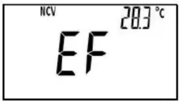
Figure 3
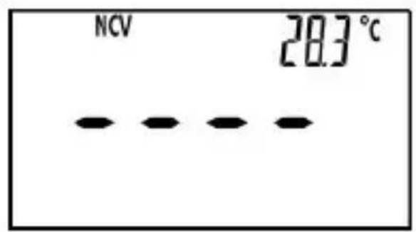
Figure 4
Note:
- Detection Range: 90V - 1000V
Required Voltage Frequency: 50Hz/60Hz
-
The optimal detecting position of the meter is at the " " mark on the meter clamp.
-
If an ac voltage is not within the meter's detecting capacity/distance, the meter can not detect this voltage.
-
The meter's electric field intensity indication is affected by the magnitude of the ac voltage of the conductor under test, the distance between the meter and the conductor, the insulation of the conductor etc.
-
Because of the meter's detection limit, a line ( or conductor) under test may be electrically live even if the buzzer does not sound, the red light does not flash and the display does not indicate the presence of electric field.
- Before and after each use, verify the meter's operation by detecting a known AC voltage. Do not use the meter if it operates abnormally or malfunctions.
- To avoid electric shock, do not touch any conductor with your hand or skin.
- To avoid interference, don't perform non-contact ac voltage detection in an environment with strong electromagnetic field; otherwise the detection result may be wrong.
Automatic Power-Off
The meter will turn off automatically and go into Sleep mode if you have operated the meter for about 15 minutes. To arouse the meter from Slee just press a button.
To disable the automatic power-off feature, turn the rotary switch from "OFF" position to other switch settings while holding down the Function
Selector Button; the symbol will be absent from the display.
MAINTENANCE
Warning
Except for replacing batteries, never attempt to repair or service the mete
Store the meter in a dry place when not in use. Don't store it in an environment with intense electromagnetic field.
General Maintenance
Periodically wipe the case with a damp cloth and a little mild detergent. not use abrasives or solvents.
Dirt or moisture in the terminals can affect readings. Clean the terminals follows:
- Set the rotary switch to OFF position and remove all the test leads from the meter.
- Shake out any dirt which may exist in the terminals.
- Soak a new swab with alcohol.
- Work the swab around in each terminal.
If the meter fails, check and replace (as needed) the batteries and/or review this manual to verify proper use of the meter.
Replacing the Batteries
Warning
To avoid false readings, which could lead to possible electric shock or personal injury, replace the batteries as soon as the low battery indicates.
Turn off the meter, remove the test leads from the meter and the met clamp from any conductor under test before opening the case or the battery cover.
When the low battery indicator appears on display, the batteries are not high enough and must be replaced immediately.
To replace the batteries, remove the screw on the battery cover and remove the battery cover. Replace the exhausted batteries with new ones of the same type, make sure that the polarity connections are correct. Reinstall the battery cover and the screw.
ACCESSIONS
Manual: 1 piece
Test Lead: 1 pair
PRESENT
K Type Thermocouple: 1 piece
NOTE
- This manual is subject to change without notice.
- Our company will not take the other responsibilities for any loss.
- The contents of this manual can not be used as the reason to use the meter for any special application.
DISPOSAL OF THIS ARTICLE
Dear Customer,
If you at some point intend to dispose of this article, then please
keep in mind that many of its components consist of \
materials, which can be recycled.
Please do not discharge it in the garbage bin,
but check with your local council for recycling
facilities in your area.
This device complies with Part 15 of the FCC Rules.
Operation is subject to the following two conditions:
(1)This device may not cause harmful interference,
and (2) this device must accept any interference receiv
including interference that may cause undesired operat

Made In China
VEVOR
TOUGH TOOLS, HALF PRICE
Technical Support and E-Warranty Certificate https://www.vevor.com/support
VEVOR
TOUGH TOOLS, HALF PRICE
www.vevor.com/support
PINCE MULTIMÉTRE TRMS MANUEL D'UTILISATION
MODELE : EM4659
Machine Translated by Google

Machine Translated by Google

PANNELLO FRONTALE

1. Mascelle
Machine Translated by Google


| ——[1] |
| ——[1] | |||
Frequenza
| Allineare | Risoluzione | Precisione | Osservazione |
| 9.999Hz | 0,001 Hz | ± (1,0% + 5) | Autorange |
| 99,99 Hz | 0,01 Hz | ||
| 999,9 Hz | 0,1 Hz | ||
| 9999kHz | 0 001kHz | ||
| 99,99kHz | 0,01 kHz | ||
| 999,9kHz | 0,1kHz | ||
| 9,999 MHz | 0,001 MHz | non specificato |
Machine Translated by Google
MIN
MAX


MAX/MIN


VFD V


REL ZERO


VFD
Machine Translated by Google


VEVOR
TOUGH TOOLS, HALF PRICE
VEVOR
TOUGH TOOLS, HALF PRICE
VEVOR
TOUGH TOOLS, HALF PRICE
ABRAZADERA TRMS
MULTIMETRO
MODELO:EM4659

NECESITA AYUDA? jCONTÁCTENOSI!
Machine Translated by Google

Machine Translated by Google

PANEL FRONTAL

1. Mandibulas
Machine Translated by Google


| ——[1] |
| ——[1] | |||
Frecuencia
| Rango | Resolución | Exactitud | Observación |
| 9.999Hz | 0,001 Hz | ± (1,0% + 5) | Rango automatístico |
| 99,99 Hz | 0,01 Hz | ||
| 999,9 Hz | 0,1 Hz | ||
| 9999kHz | 0 001 kHz | ||
| 99,99 kHz | 0,01 kHz | ||
| 999,9 kHz | 0,1 kHz | ||
| 9,999 MHz | 0,001 MHz | No especial加固 |
Machine Translated by Google
MIN
MAX


MAX/MIN


VFD V


REL ZERO


VFD
Machine Translated by Google


VEVOR
TOUGH TOOLS, HALF PRICE
VEVOR
TOUGH TOOLS, HALF PRICE
VEVOR
TOUGH TOOLS, HALF PRICE
Zacisk TRMS
MULTIMETR
MODEL:EM4659

POTRZEBUJESZ POMOCY? SKONTAKTUJ SIE Z NAMI!
Machine Translated by Google

Machine Translated by Google

PANEL PRZEDNI

- Szczeki
Machine Translated by Google

| ——[1] |
| ——[1] | |||
Czestotliwość
Machine Translated by Google
MIN
MAX


MAX/MIN


VFD V


REL ZERO


VFD
Pomiar pradu VFD
Machine Translated by Google


VEVOR
TOUGH TOOLS, HALF PRICE
VEVOR
TOUGH TOOLS, HALF PRICE
VEVOR
TOUGH TOOLS, HALF PRICE
TRMS-KLEM
MULTIMETER
MODEL:EM4659
HULP NODIG? NEEM CONTACT MET ONS OP!
Klantenservice@vevor.com
Machine Translated by Google

Machine Translated by Google

VOORPANEL

1. Kaken
Machine Translated by Google


| ——[1] |
| ——[1] | |||
Frequentie
| Bereik | Oplossing | Nauwkeurigheid | Opmerking |
| 9,999 Hz | 0,001 Hz | ± (1,0% + 5) | Automatisch bereik |
| 99,99 Hz | 0,01 Hz | ||
| 999,9 Hz | 0,1 Hz | ||
| 9999 kHz | 0 001kHz | ||
| 99,99 kHz | 0,01kHz | ||
| 999,9 kHz | 0,1 kHz | ||
| 9,999 MHz | 0,001 MHz | niet gespecificerd |
Machine Translated by Google
MIN
MAX


MAX/MIN


VFD V


REL ZERO

VFD
VFD-stroom meten
Machine Translated by Google


VEVOR
TOUGH TOOLS, HALF PRICE
VEVOR
TOUGH TOOLS, HALF PRICE
VEVOR
TOUGH TOOLS, HALF PRICE
TRMS KLÄMMA MULTIMETER
MODELL:EM4659

BEHÖVER HJÄLP? KONTAKTA OSS!
Machine Translated by Google

Machine Translated by Google

FRAMPANEL
1. Käftar
8. " INPUT " Terminal
Machine Translated by Google


| ——[1] |
| ——[1] | |||
Frekvens
| Räckvidd | Upplösning | Noggrannhet | Anmärkning |
| 9,999 Hz | 0,001 Hz | ± (1,0 % + 5) | Autorange |
| 99,99 Hz | 0,01 Hz | ||
| 999,9 Hz | 0,1 Hz | ||
| 9999 kHz | 0 001 kHz | ||
| 99,99 kHz | 0,01 kHz | ||
| 999,9 kHz | 0,1 kHz | ||
| 9,999 MHz | 0,001 MHz | inte specificerat |
Machine Translated by Google
MIN
MAX


MAX/MIN


VFD V


REL ZERO


VFD
Machine Translated by Google


Machine Translated by Google
Machine Translated by Google
VEVOR
TOUGH TOOLS, HALF PRICE