
FRB-1M3 - Heating Vevor - Free user manual and instructions
Find the device manual for free FRB-1M3 Vevor in PDF.
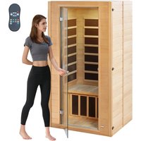


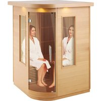
| Product type | Wooden sauna with infrared heating |
| Brand | Vevor |
| Model | FRB-1M3 |
| Power | 1400 W |
| Input voltage | AC 220-240 V, 50 Hz |
| Approx. dimensions | Approx. 1 m³ (interior volume) |
| Material | Wood (type not specified) |
| Main functions | Infrared heating, LED lighting, Bluetooth player, remote control |
| Control panel | Digital with temperature display and timer |
| Maximum temperature | Approx. 60°C for children, not specified for adults |
| Timer | Yes, adjustable via control panel |
| Safety | Automatic shut-off recommended after 3 hours, do not leave unattended |
| Maintenance | Clean with a damp cloth, do not use solvents |
| Spare parts | Bulbs, heaters, control panels, cables |
| Warranty | Electronic warranty certificate at www.vevor.com/support |
Frequently Asked Questions - FRB-1M3 Vevor
User questions about FRB-1M3 Vevor
0 question about this device. Answer the ones you know or ask your own.
Ask a new question about this device
Download the instructions for your Heating in PDF format for free! Find your manual FRB-1M3 - Vevor and take your electronic device back in hand. On this page are published all the documents necessary for the use of your device. FRB-1M3 by Vevor.
USER MANUAL FRB-1M3 Vevor
Technical Support and E-Warranty Certificate www.vevor.com/support
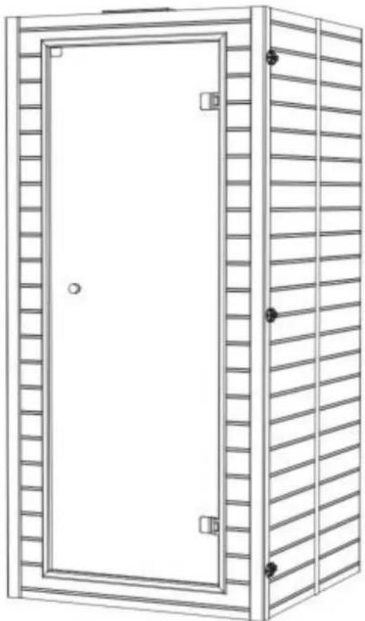
WOOD SAUNA
MODEL: FRB-1M3
We continue to be committed to providing you with tools at competitive prices. "Save Half", "Half Price", or any other similar expressions used by us represent an estimate of savings you might benefit from buying certain tools from us compared to the major top brands, and do not necessarily mean that all categories of tools offered by us are at such savings. You are kindly reminded to verify when placing an order with us whether you are actually saving compared to the top major brands.
MODEL: FRB-1M3
NEED HELP? CONTACT US!
Have product questions? Need technical support? Please feel free to contact us: Technical Support and E-Warranty Certificate www.vevor.com/support
This is the original instruction. Please read all manual instructions carefully before use. VEVOR reserves a clear interpretation of our user manual. The appearance of the product shall be subject to the product you received. Please forgive us that we won't notify again if there are any technology or software updates on our product.
Recommendations
Read this manual carefully before using your sauna for the first time.
We recommend you keep it in a safe place for future reference.
Wood is a living element. To maintain its original appearance, it is important to treat the wood against moisture.
Use a saturator only on the outside of the sauna.
Install the sauna on a perfectly flat and hard surface.
The sauna must remain in a dry area. Do not use it near a source of water (bath, shower, swimming pool).
- Do not use liquid cleaning products. Disconnect the sauna before cleaning and use a we
- Protect the sauna's electrical cable to avoid it being crushed or pinched.
- Prior to replacing certain components, ensure that they are specified by the manufacturer and have the same features
as the original parts. Incorrect replacement can cause a fire, a short circuit, or damage. We strongly recommend
using a qualified technician.
- To avoid the risk of burns or electric shocks, do not use any metal tools.
- Do not put animals in the sauna.
- Do not leave the sauna switched on without supervision.
- Do not leave the sauna switched on for more than 3 hours at a time to avoid premature deterioration of the equipment. After 3
hours of continuous usage, switch off the sauna for at least one hour.
- We recommend that you do not install a locking system on the sauna door.
- Check compliance of your electrical installation prior to connecting your sauna to the power supply.
IMPORTANT:
Please read the safety instructions carefully before installing and using your sauna cabin. They are essential for your safety, so please adhere strictly to them.
Beware of hyperthermia, heat stroke, or heat exhaustion, which can be caused or aggravated by noncompliance with the safety instructions. Symptoms include fever, rapid pulse, dizziness, faintness, lethargy, and numbness in all or part of the body. The effects include reduced awareness, ignorance of imminent risks, and loss of consciousness.
The sauna must not be used by:
• Children under 6 years of age.
• People with severe reactions to sunlight.
• Elderly or disabled people.
• People with previous medical conditions such as heart disease, high or low blood pressure, circulation problems or diabetes without prior medical advice.
• Pregnant women. Excessive temperature can endanger the foetus.
• Persons suffering from dehydration, open sores, eye disorders, burns or sunstroke.
Children between 6 and 16 years of age may use the sauna provided that they are accompanied by a responsible adult and that the temperature does not exceed 60°C (140°F). In the event of health problems, medication, or muscle or ligament injuries, do not use the sauna without previously consulting a doctor and obtaining approval.
If surgical implants are worn, do not use the sauna without previously consulting a doctor and obtaining his approval. Do not use the sauna after strenuous activity.
Wait 30 minutes for your body to cool down.
Do not spend more than 40 minutes in the sauna at any one time. Do not consume alcohol before or during the session.
Do not sleep in the sauna when it is in operation.
To avoid the risk of overheating, connect your sauna to a sufficiently powerful electrical outlet. Do not connect other electrical equipment to the same wall socket.
To avoid any risk of electrocution or damage to the sauna, do not use it:
• During thunderstorms.
- If the electrical cable is damaged, it must be replaced by a qualified person.
- If the electrical cable overheats, it must be checked by a qualified person.
- If you have to change a bulb, wait until the sauna is switched off and cooled down.
Dry your hands before connecting or disconnecting the electricity. Never work with wet hands. Do not switch the electricity or the heating system rapidly on or off as this could damage the electrical system. Do not try to repair the sauna by yourself without the agreement of the distributor or manufacturer.
Unauthorized attempts to repair it will invalidate the manufacturer's warranty.
Do not use any type of detergent inside the sauna.
Do not pile up or store objects inside or on top of the sauna.
Do not place flammable materials or chemical agents near the sauna.
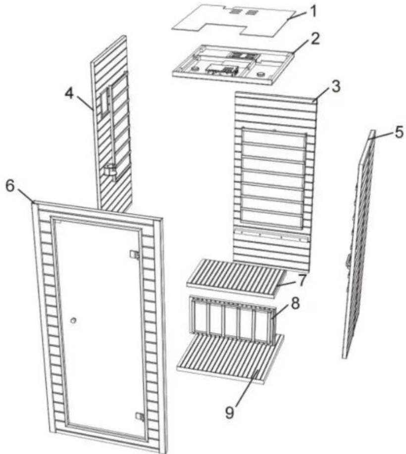
| 1 | Duster cover *1 | 5 | Left board *1 | 7 | Bench *1 |
| 2 | Top board *1 | 5 | Right board *1 | 8 | Bench front board *1 |
| 3 | Back board *1 | 6 | Front board *1 | 9 | Bottom board *1 |
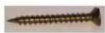
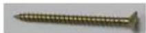
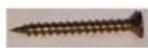
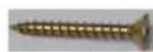
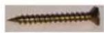
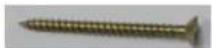
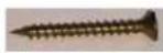
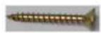
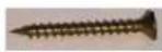
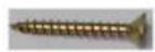
Screw (3*25) * 10
Screw (4*50) * 8
Screw (3*35) * 7
Screw (4*30) * 4

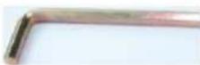
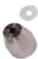
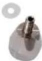
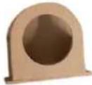
Towel racks * 1
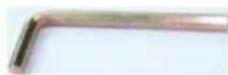
Hexagon Wrench * 1
Handles * 1
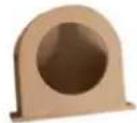
Cup holders*1
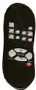
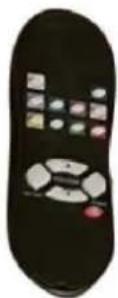
Remote control*1
| Model | Power(W) | Voltage(V) | Frequency(Hz) | Plug Type |
| FRB-1M3 | 1400 | AC 220-240 | 50 | European Standard |
| AC 220-240 | 50 | Ausstandard | ||
| AC 120 | 60 | American Standard |
INSTALLATION PROCEDURE
CAUTION:
1) No plumbing or plumbing fixtures should be placed in the sauna. 2) Keep all liquids away from the heating panels. 3) Install sauna on a completely level surface. 4) Install sauna in an area that is dry. 5) Flammable objects and corrosive chemical substances should be kept far away from the sauna.
Step 1
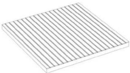
Take out the base plate and place it on a flat ground for installation.
Step 2
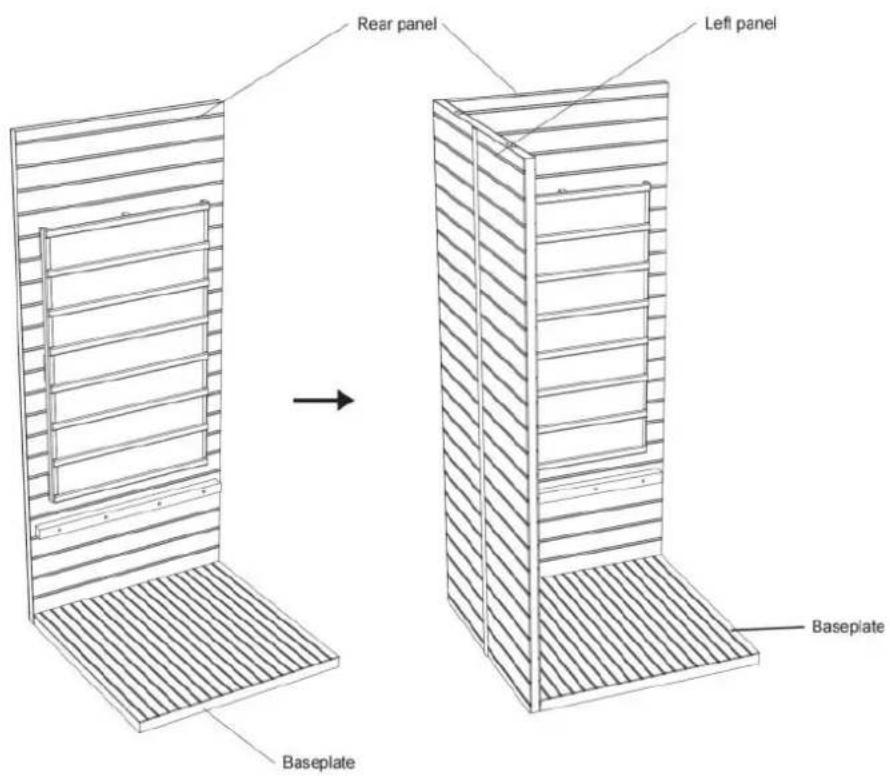
Take out the rear panel and left panel, and stand them at the corresponding position behind the base plate.
Step 3
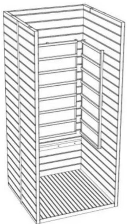
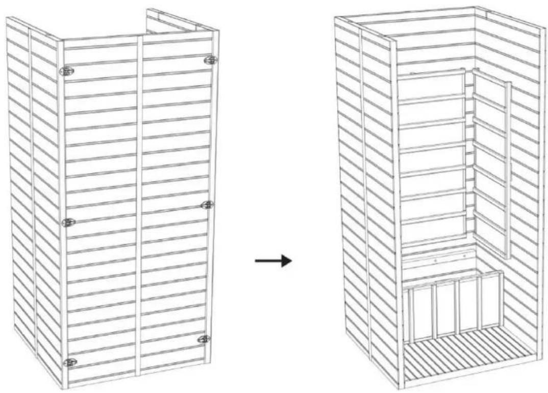
Install the left and right side panels:
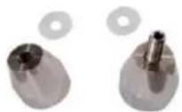
The left and right side panels are fixed to the rear panel through a buckle connection.
![graph TD A["Outer buckle installation method"] --> B["Step 1: Initial state with bolt holes"] B --> C["Step 2: Final assembled component with ring and mounting holes"] C --> D["Step 3: Final assembly with ring and mounting holes"]](/content/2026/04/734563/images/2e3fd9c567e3f95fc68a91aa694b1e25b66ae0c6a584e5297ce403ee461b8468.jpg)
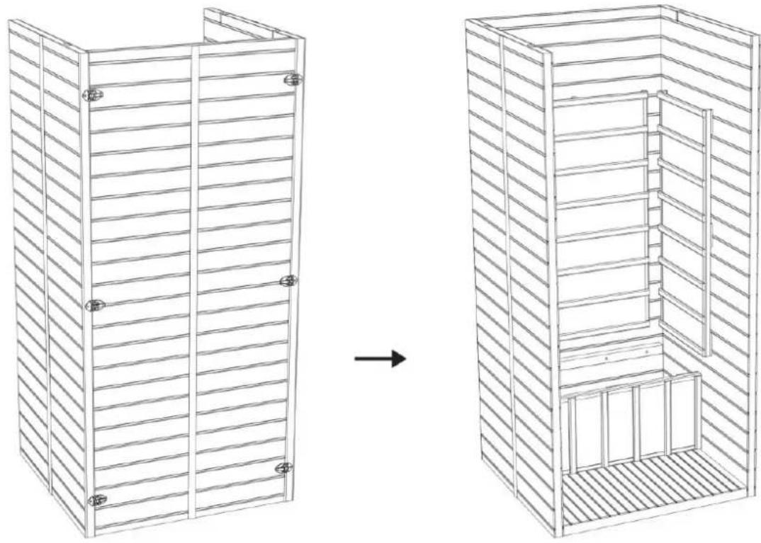
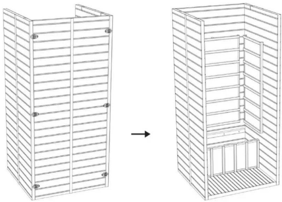
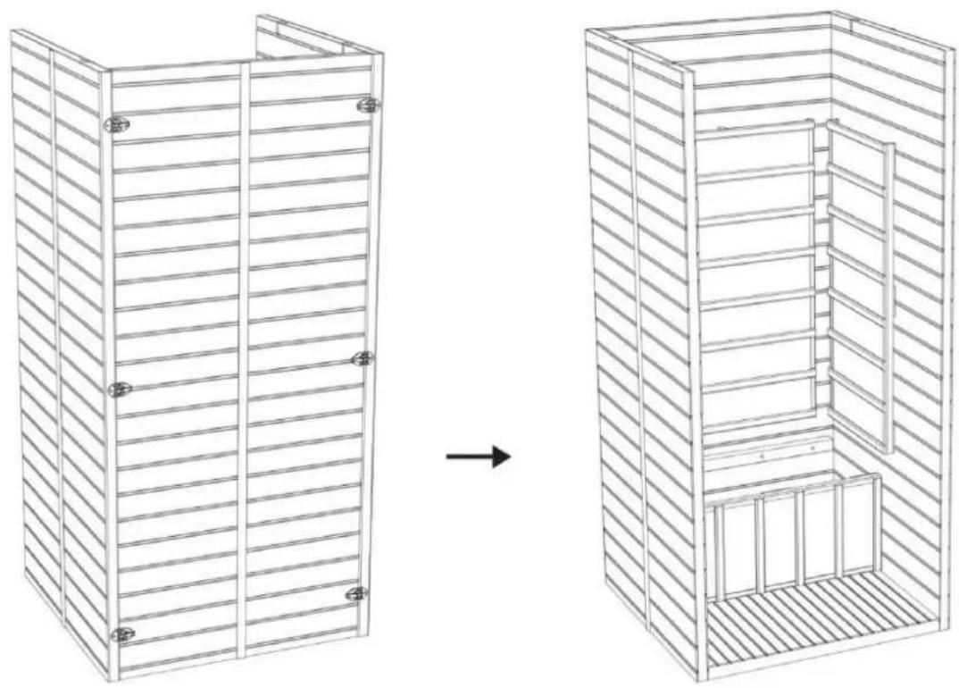
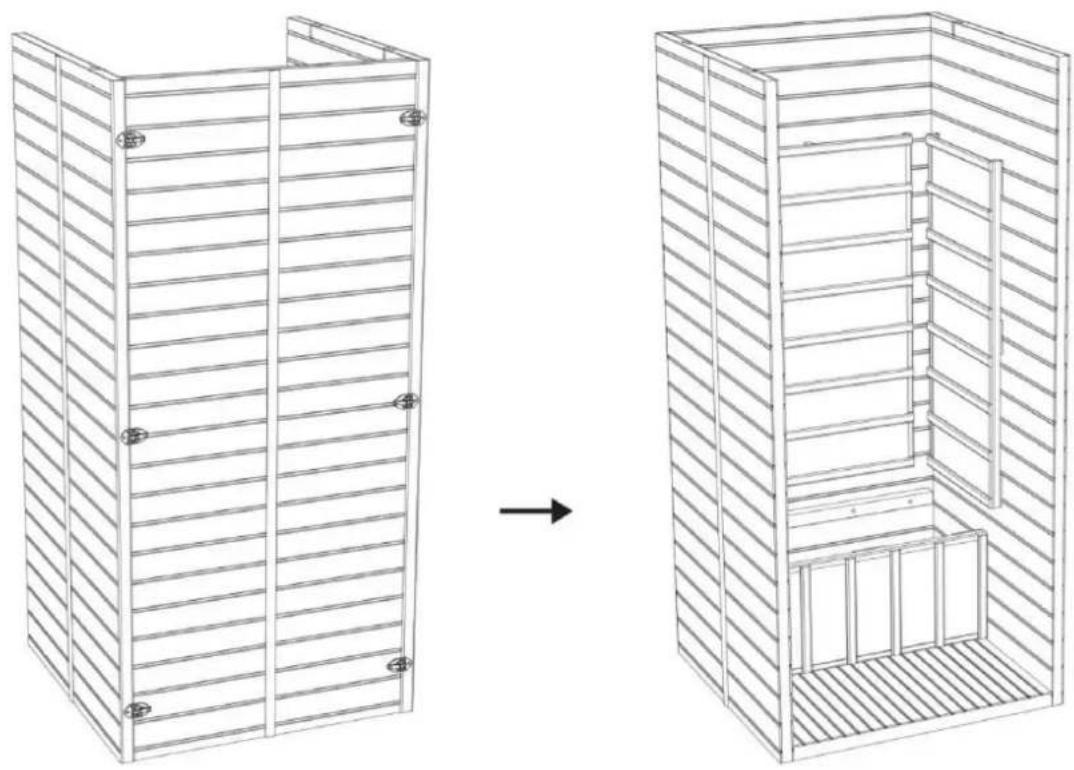
Step 4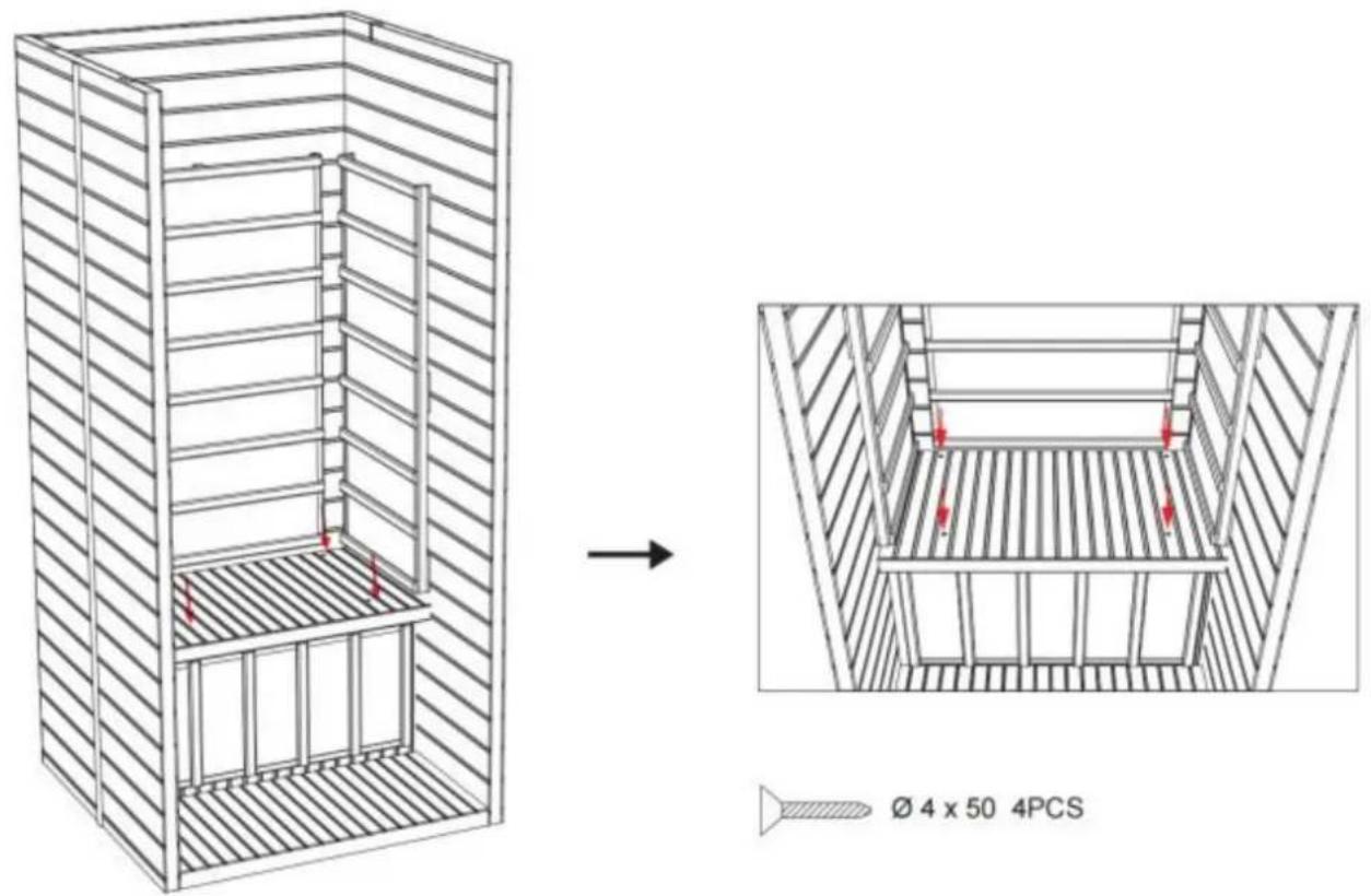
Step 5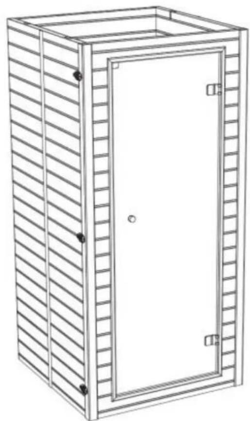
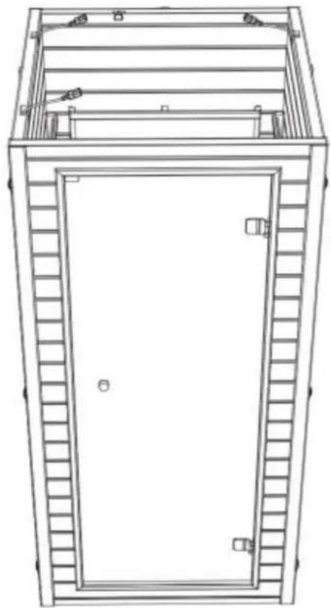
Step 6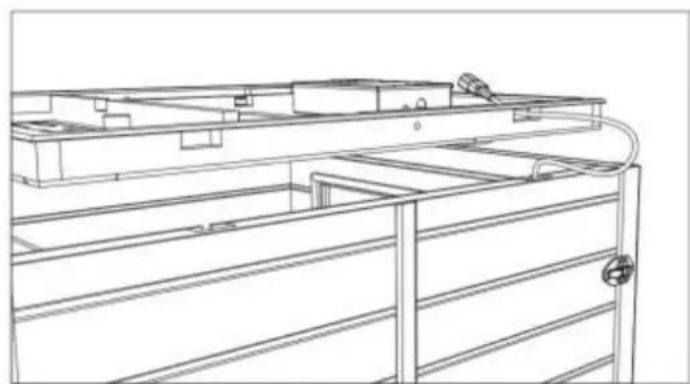
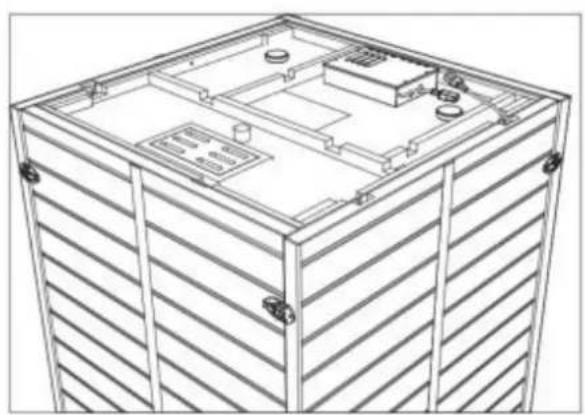
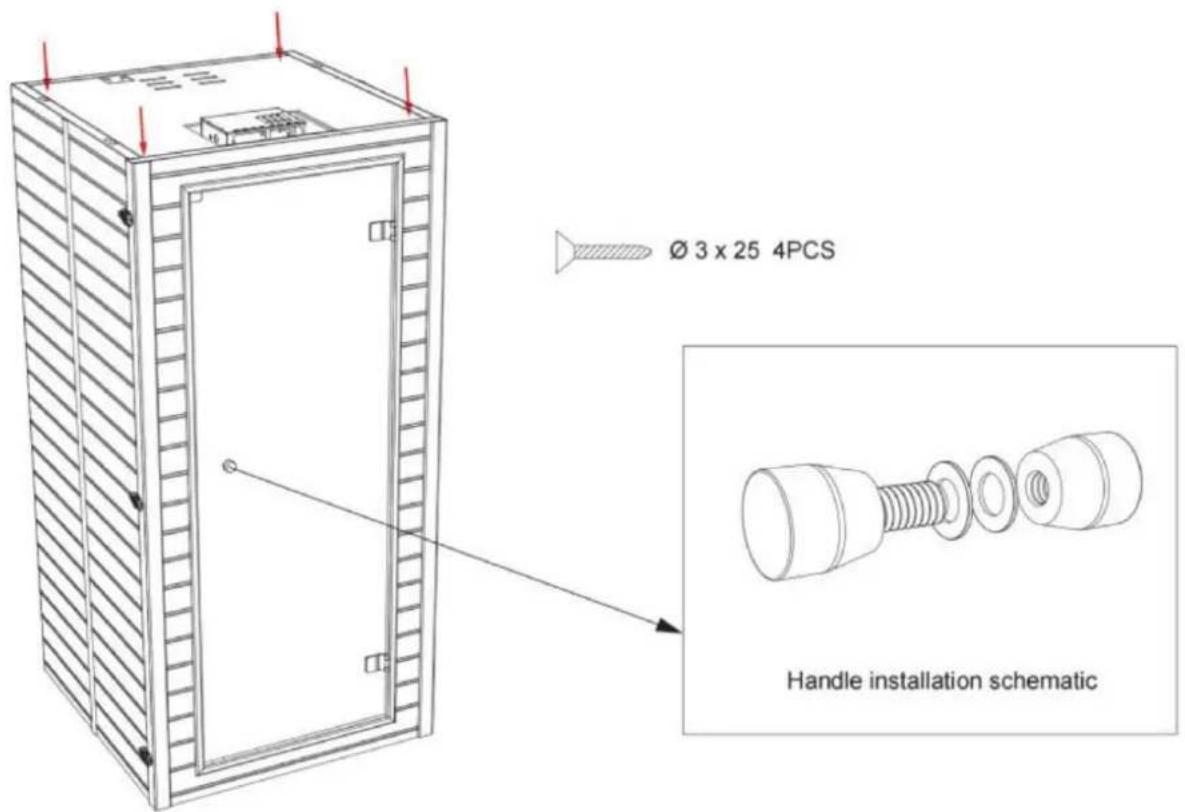
Step 7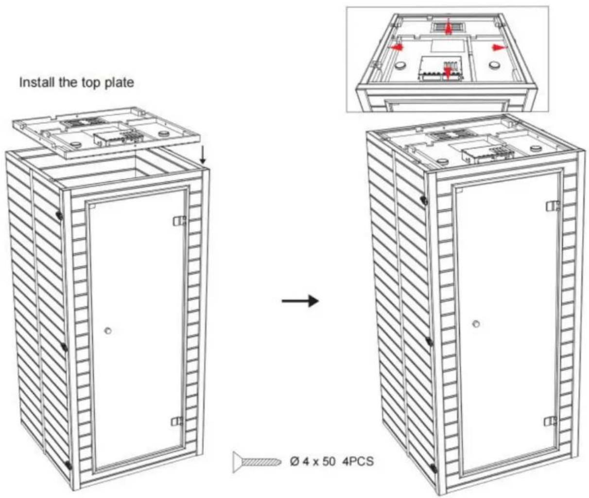
Step 8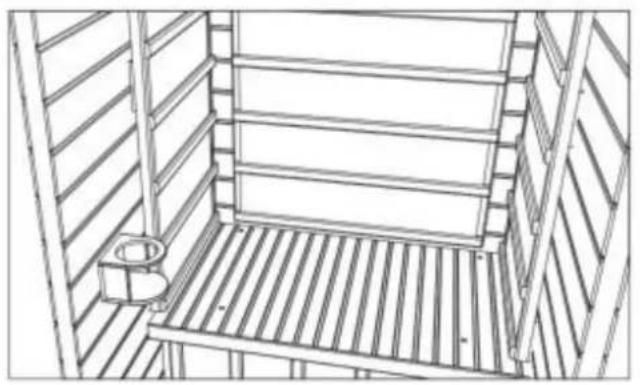
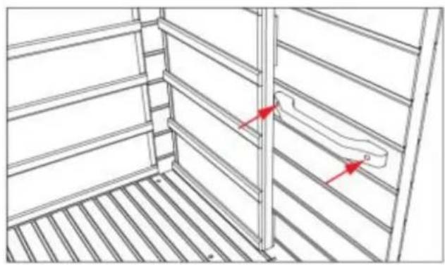
∅ 3 × 35 2PCS
Step 9
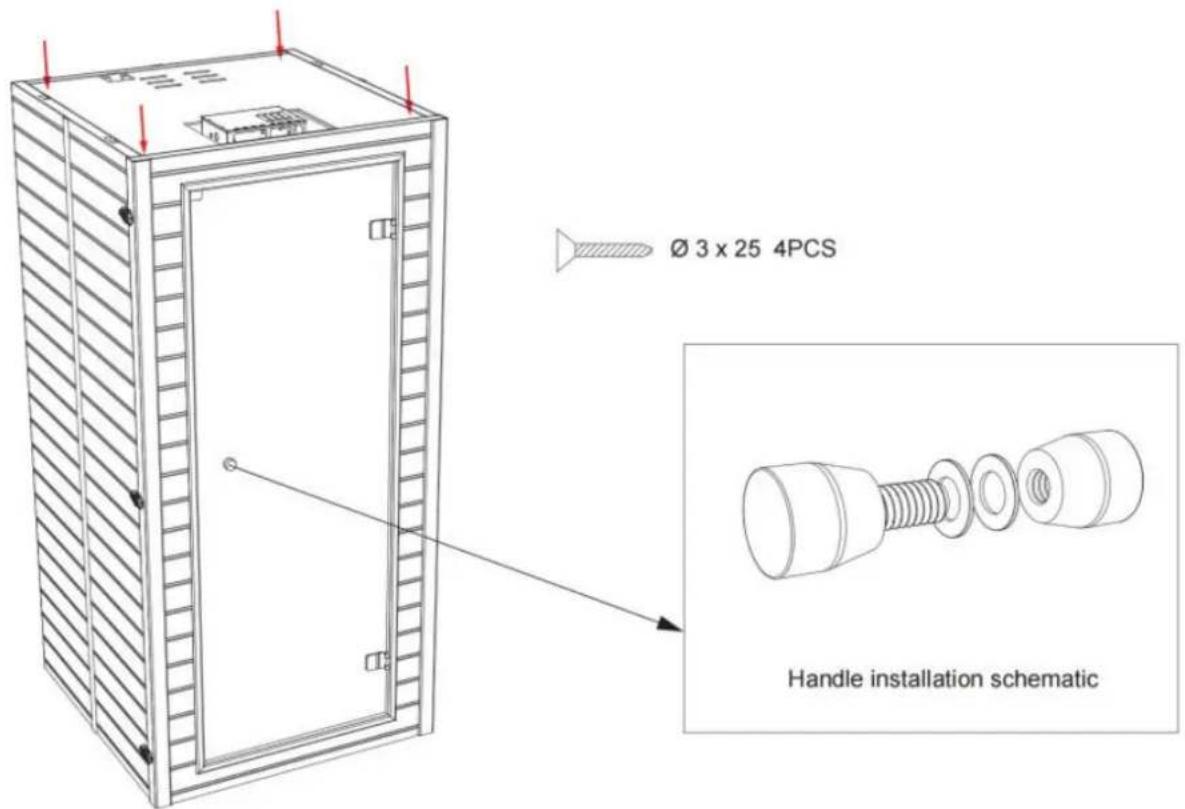
Operation
1. Precautions
a. Check all the circuitry and the plug meet all requirements.
b. Set the temperature and time to a comfortable level.
c. Drink a cup of water before the sauna session.
d. After 2 hours of continuous use, shut the sauna down for one hour.
e. To avoid burns, do not touch the heating element.
f. WARNING: Covering the heater or infrared emitter causes fire risk!
2. Operation
a. Plug the sauna into an outlet which is stated on the nameplate. Do not share the outlet with other appliances.
The sauna should be unplugged when not in use.
b. After your sauna session, turn off and unplug the power cable.
C. DO NOT OPERATE THE SAUNA UNSUPERVISED TO REDUCE THE RISK OF FIRE.
Note:
When the environmental temperature is low, the heating time will take longer.
It is also possible that the sauna temperature display is not able to reach its maximum temperature.
This is normal and does not in any way affect the performance of the infrared heater health benefits. The sauna temperature sensor only measures the heat radiated by the heating elements.
It does not measure the infrared heaters' penetrating heat, and this is where most of the health benefits are.
Control panel operation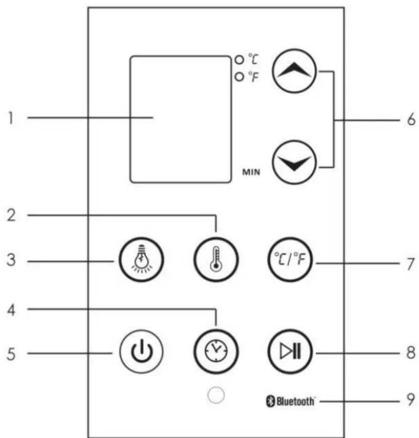
| 1 | Display screenFor temperate and timer displa | 6 | Adjust buttonPress '^' and 'V' to adjust the tempera setting and the timer setting. |
| 2 | Temperature buttonPress the key to temperature adjustment state. | 7 | Temperature typePress to change the temperature displabetween °C/°F. |
| 3 | Light buttonPress the key to turn on/off the | 8 | Pause/PlayPress to control the working functions of sauna. |
| 4 | Time buttonPress the key to time adjustme state. | 9 | BluetoothControl panel can be connected to device play music. |
| 5 | Power buttonPress the key to turn on/off t sauna. |
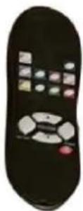
INTRODUCTION OF REMOTE
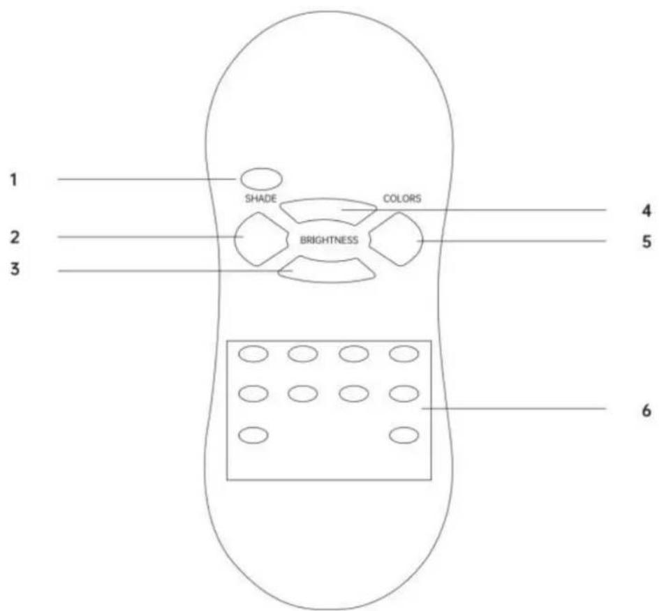
| 1 | Turn on/ off buttonPress the button to turn on or of light. | 4 | Brightness+Press the button to decrease the brightne |
| 2 | ShadePress the button to changing light automatically. | 5 | ColorsPress the button to change colors manua |
| 3 | Brightness-Press the button to decrease the brightness. | 6 | Changing lights buttonPress any one of the button to choose favorite color. |
![graph TD A["Speaker Speaker"] --> B["control panel"] C["Temperature sensor"] --> B D["Color light"] --> E["Control power box"] F["Rear wall panel Heater 1"] --> G["Bench wall panel Heater"] H["Rear wall panel Heater 2"] --> I["Left side wall panel Heater"] J["Right side wall panel Heater"] --> K["Co…](/content/2026/04/734563/images/407298e3246b2b0c13ab90066468bc188a77d316662b9a402462bddef7f02c5a.jpg)
Maintenance
| Before using | 1.Please be sure to follow the instruction manual beforeoperations;2.Prepare a towel on the seat bench to prevent sweatfrom dripping or avoid affecting the quality andbeauty of wood. |
| After using | 1.Please unplug the power plug in time;2.Open the door to let the heat and humid water vapordissipate and sauna cabin dry. |
| Stain on wood | 1.The outer cabin can be wiped with a wrung wet towel;The inner ca wiped by small vacuum cleaner.2.Do not use organic solvents to decontaminate,such asgasoline,alcohol,etc.wipe the sauna surface;3.Do not use sharp objects in sauna cabin to preventscratching woods |
| Stain on glass | 1.Wipe the glass with soft paper;2.Stubborn stains can be wiped with a damp cloth,thendry with a dry 3.Do not scratch the surface with a sharp object to preventscratching |
| Transportation and storage | 1.Avoid water,snow and intense impact during thetransportation;2.Do not store it in a humid environment;3.The northern climate is relatively dry,often wipe theproduct with a wr towel;4.The climate in the south is relatively humid and can beventilated an frequently. |
Trouble shooting
Made In China
| Number | Problems | Possible reasons | Countermeasure |
| 1 | Indicator light for powersupply not working | The connector is not connected properly. | Check the connector or replac new one. |
| No power supply input. | Chick the circuity (especially weather there is power supp input). | ||
| Indicator light is broken. | Replace the circuity panel. | ||
| 2 | Indicator light for function is not working | The heating indicator light broken. | Replace the relevant control panel. |
| The circuit board or components are broken. | Replace the circuit board. | ||
| The temperature sensor is broken. | Check if the connect is loos and replace it. | ||
| 3 | Infrared Heater no heating up | The heater is broken. | Replace with a new one Of same specifications. |
| The wire junction or the heater's wire is loosen. | Check and make them tight | ||
| The temperature sensor is broken. | Check if junction of the temperature sensor is loosen and replace it. | ||
| The circuit board of the re is not work. | Replace the circuit board. | ||
| 4 | Odor from the sauna | The circuit's problems. | 1) There is eyewinker around remove it.2) Some heater's temperature over high,cut off the power supply,replace it.3) Parts on the circuitry is br |
| 5 | Light bulb is not working | Light bulb is burned out. | Replace the light bulb. |
| Light bulb wiring is loose | Replace the lamp holder. | ||
| Problems with electrical control panel. | Repair or replace it. | ||
| 6 | Sauna is not power up | Power cord is unplug. | Plug back power cord to out |
| Outlet has no power. | Check outlet or circuit breake | ||
| Power supply or circuit pa is broken. | Replace the power supply c related circuitry board. | ||
| 7 | Music Player doesn't work | Power connector is loose damage. | Check connector or replace |
| DC power supply is no po to the music player. | Check DC power supply wirir or replace the power supply | ||
| Music player is defective. | Replace the music player. | ||
| 8 | Speaker does not work | The speaker is broken. | Replace with a new one of same specifications. |
| The speaker wire is loose | Reconnect the speaker wire. | ||
| The power indicator light music player is off | Turn on the switch to start |
VEVOR®
TOUGH TOOLS, HALF PRICE
Technical Support and E-Warranty Certificate
Install the left and right side panels:
The left and right side panels are fixed to the rear panel through a buckle connection.
![graph TD A["Outer buckle installation method"] --> B["Step 1: External buckle assembly"] B --> C["Step 2: Rear assembly with ring and bolt holes"] C --> D["Step 3: Final mounting bracket assembly"] D --> E["Step 4: Final mounting bracket assembly with ring and bolt holes"]](/content/2026/04/734563/images/9b4843f6a89c637aaf6ebcad9c65f129d2f49da7c35c538d56f739ad8f7cdbf4.jpg)
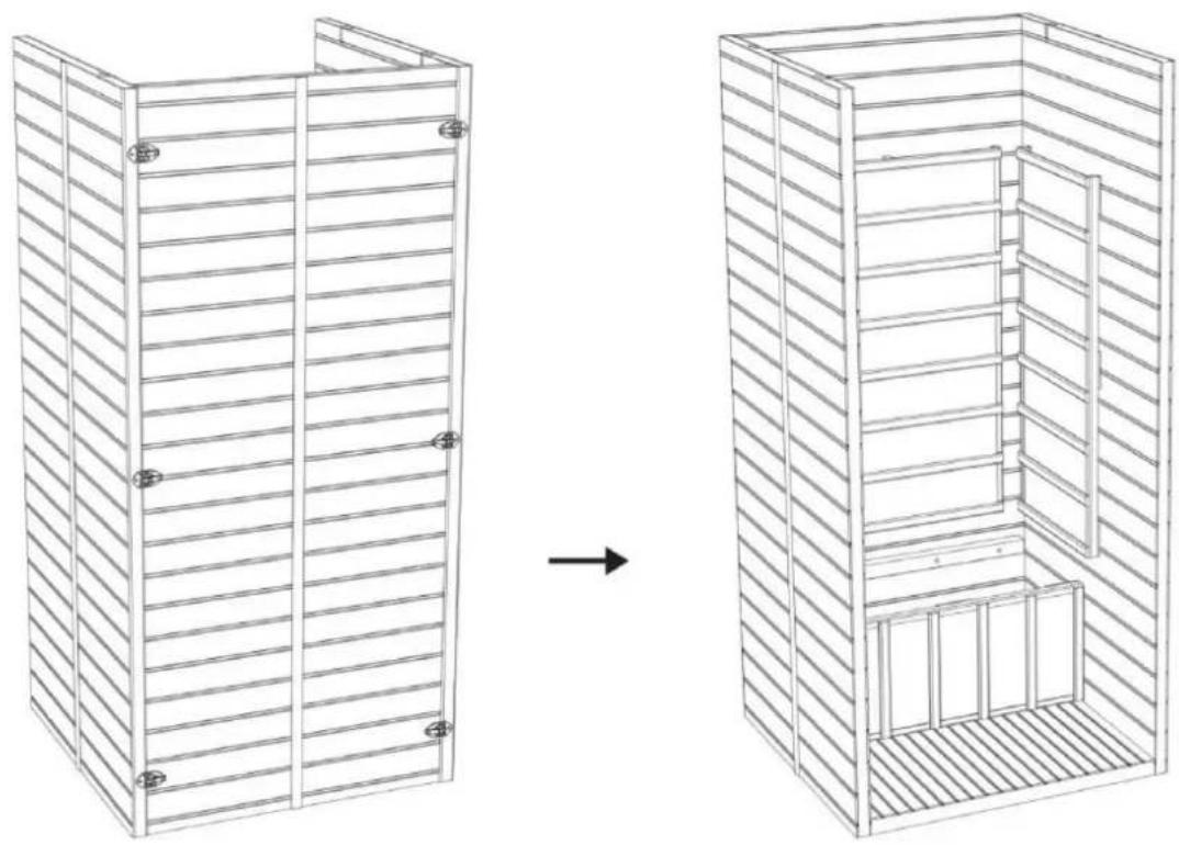
Step 4
Step 5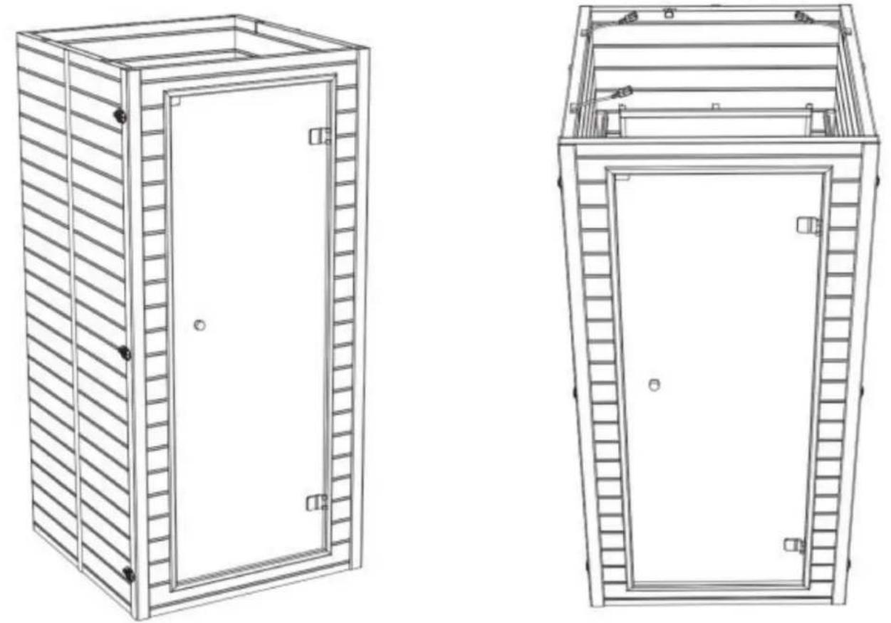
Step 6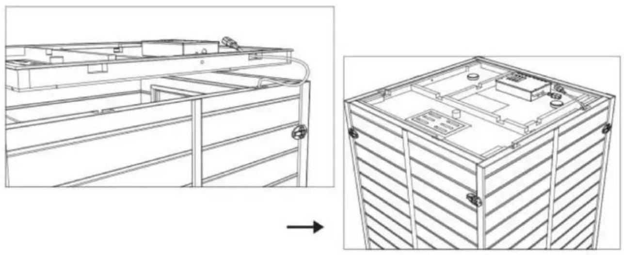
Step 7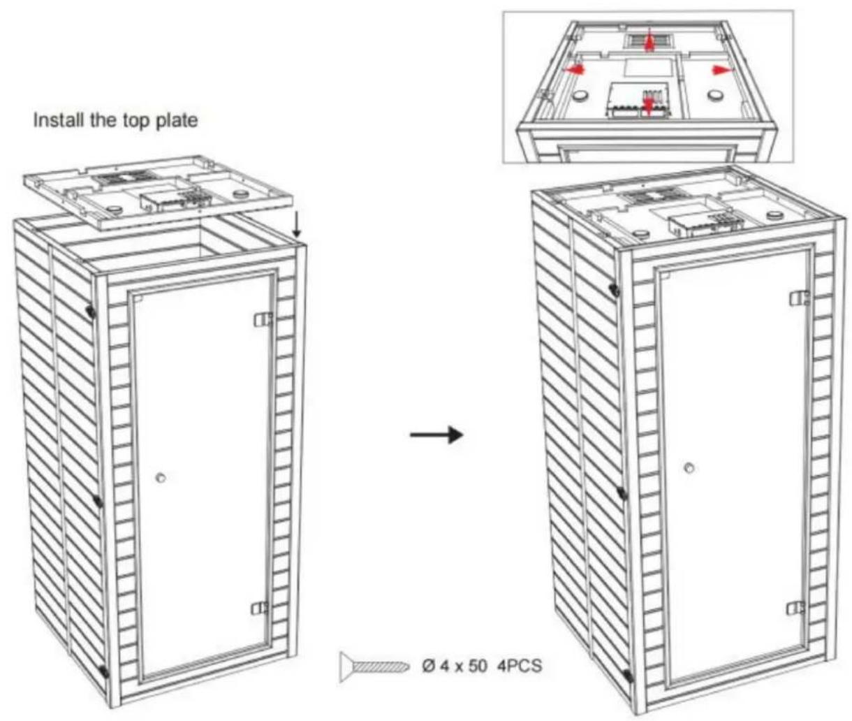
Step 8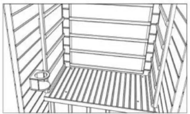
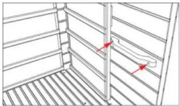
∅ 3 × 35 2PCS
Step 9
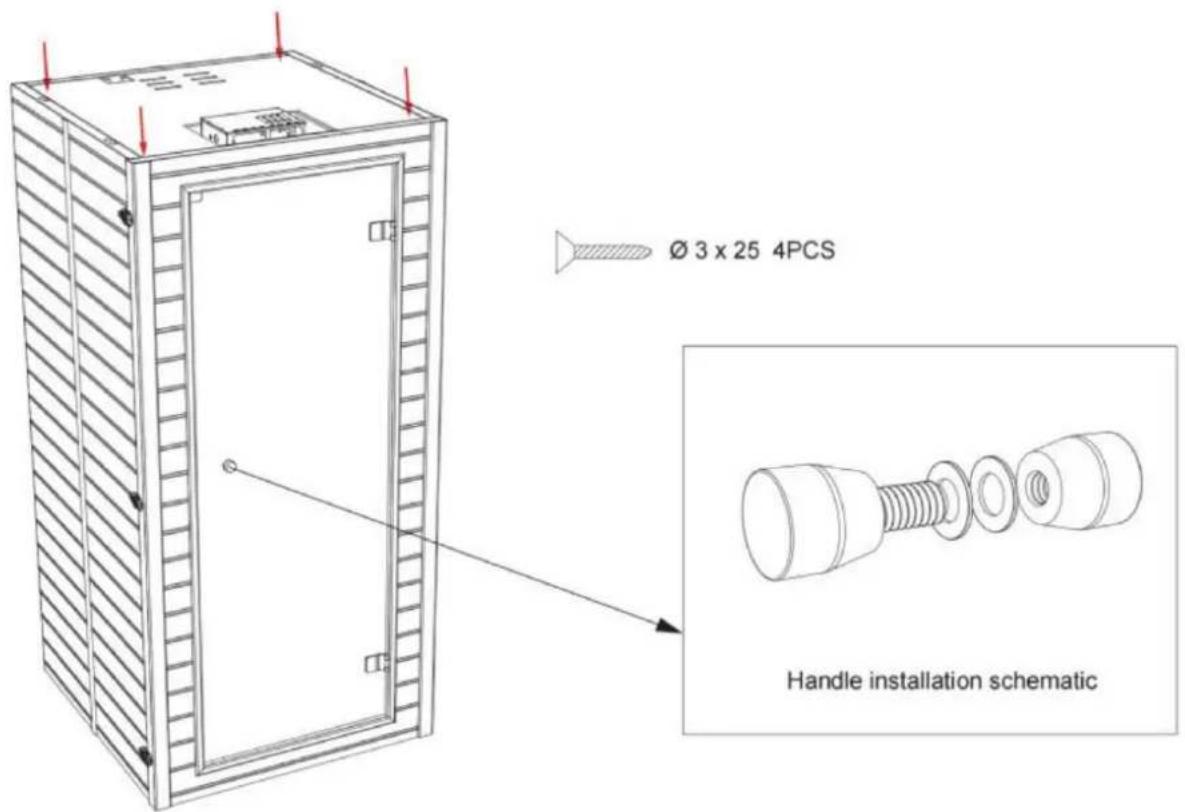
Operation
- Precautions
Maintenance
NEED HELP? CONTACT US!
| 1 | Staubtuchabdeckung *1 | 5 | Linkes Brett *1 | 7 | Bank *1 |
| 2 | Oberbrett *1 | 5 | Rechtes Brett *1 | 8 | Bankvorderbrett *1 |
| 3 | Rückwand *1 | 6 | 9 | Bodenplatte *1Frontplatte *1 |
Install the left and right side panels:
The left and right side panels are fixed to the rear panel through a buckle connection.
![graph TD A["Outer buckle installation method"] --> B["Step 1: External buckle assembly"] B --> C["Step 2: Rear assembly with ring and bolt holes"] C --> D["Step 3: Final mounting bracket assembly"] D --> E["Step 4: Final mounting bracket assembly with ring and bolt holes"]](/content/2026/04/734563/images/10693030fb7de32e2afa9b24a7ca84555ce3f34cac60d058350c0640dfcb4cfa.jpg)
Step 4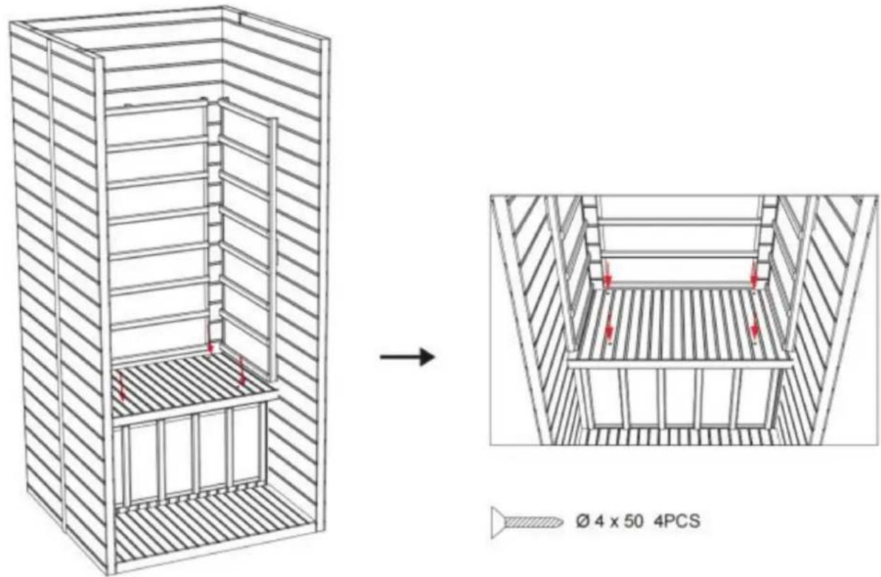
Step 5
Step 6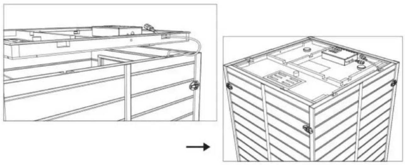
Step 7
Step 8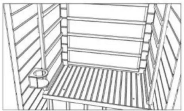
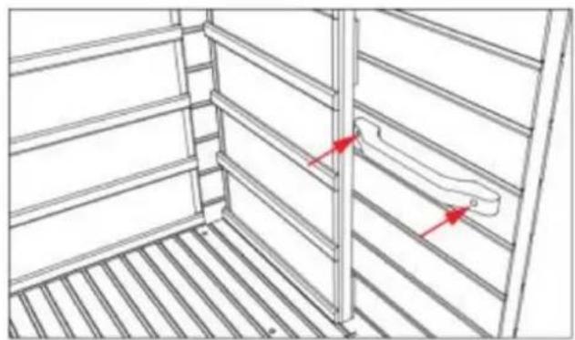
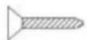
∅ 3 × 35 2PCS
Step 9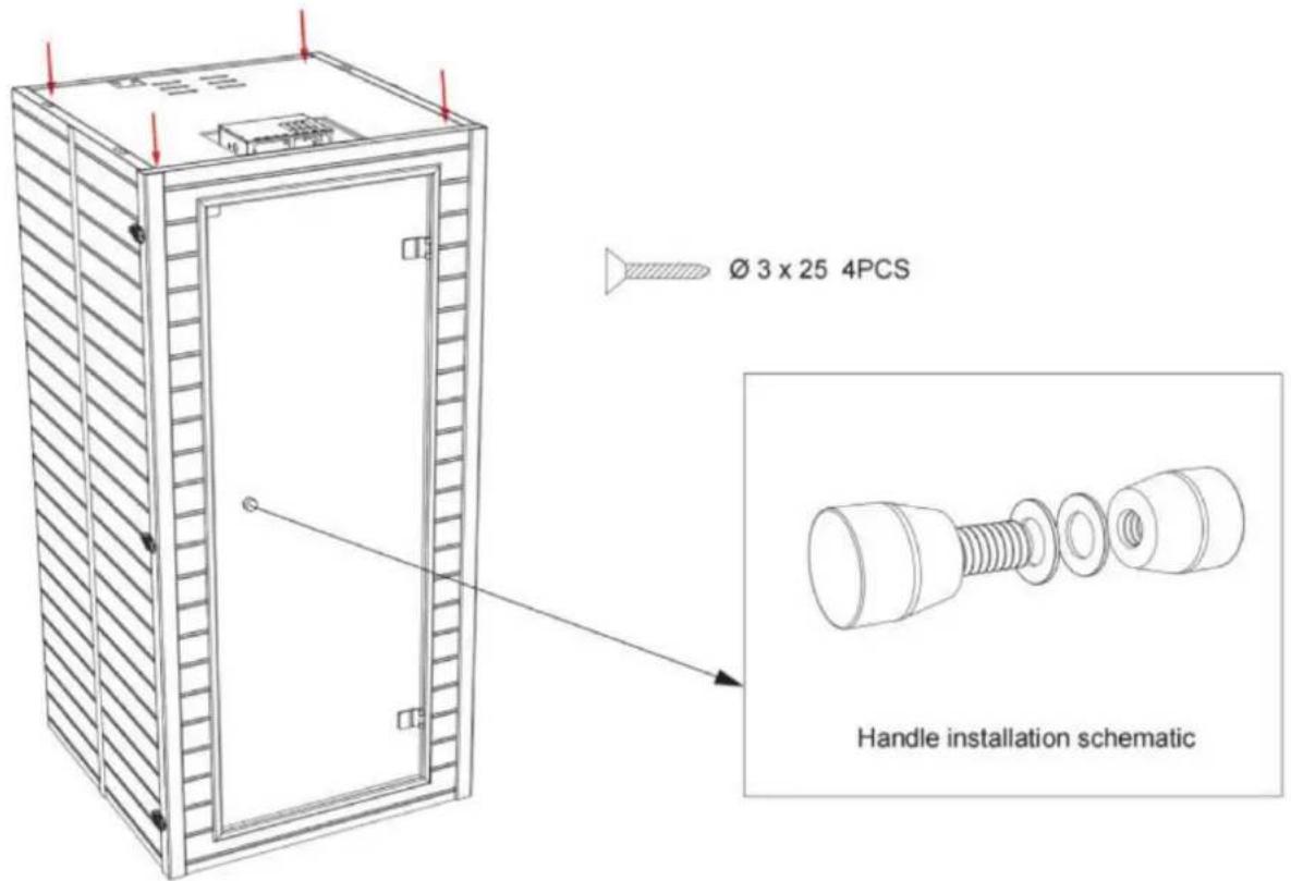
Operation
Maintenance
www.vevor.com/support
VEVOR®
TOUGH TOOLS, HALF PRICE
NEED HELP? CONTACT US!
Install the left and right side panels:
The left and right side panels are fixed to the rear panel through a buckle connection.
![graph TD A["Outer buckle installation method"] --> B["Step 1: External buckle assembly"] B --> C["Step 2: Rear assembly with ring and bolt holes"] C --> D["Step 3: Final mounting bracket assembly"] D --> E["Step 4: Final mounting bracket assembly with ring and bolt holes"]](/content/2026/04/734563/images/34b51f7db229f34bf3e80a90eea0045f7ea236916bd46d401185c71d7ec6a52e.jpg)
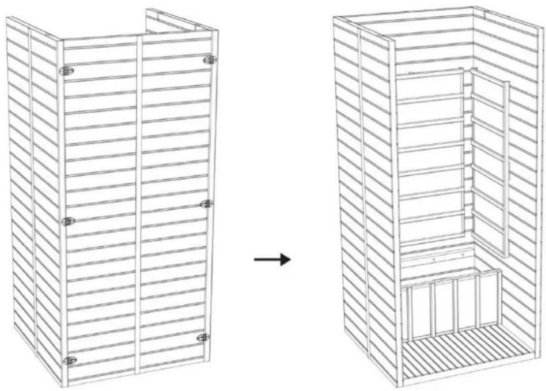
Step 4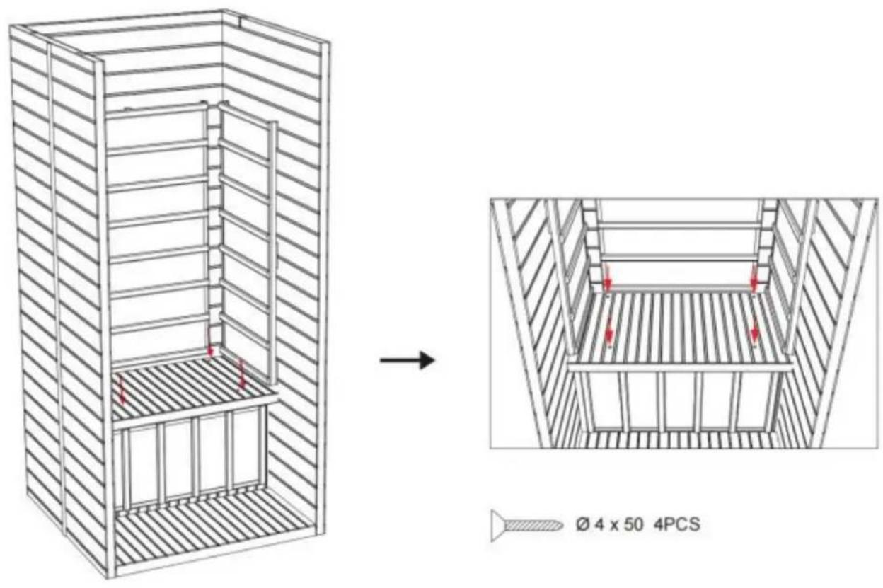
Step 5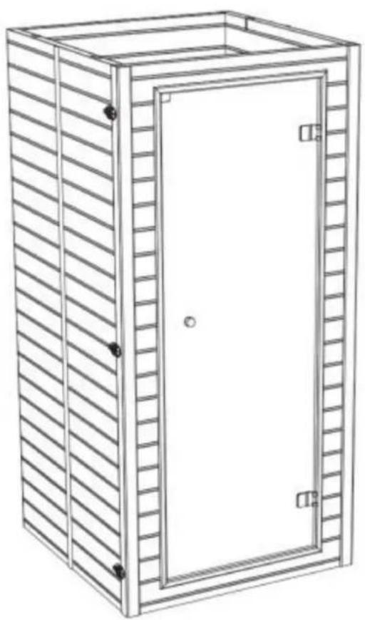
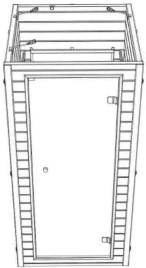
Step 6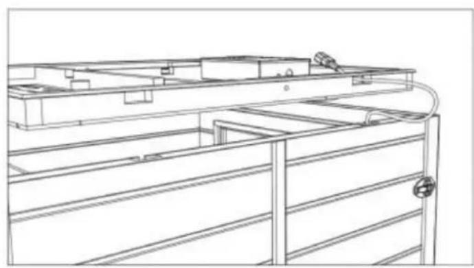
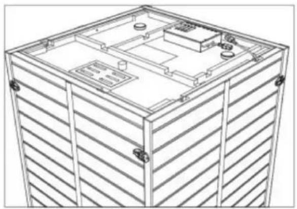
Step 7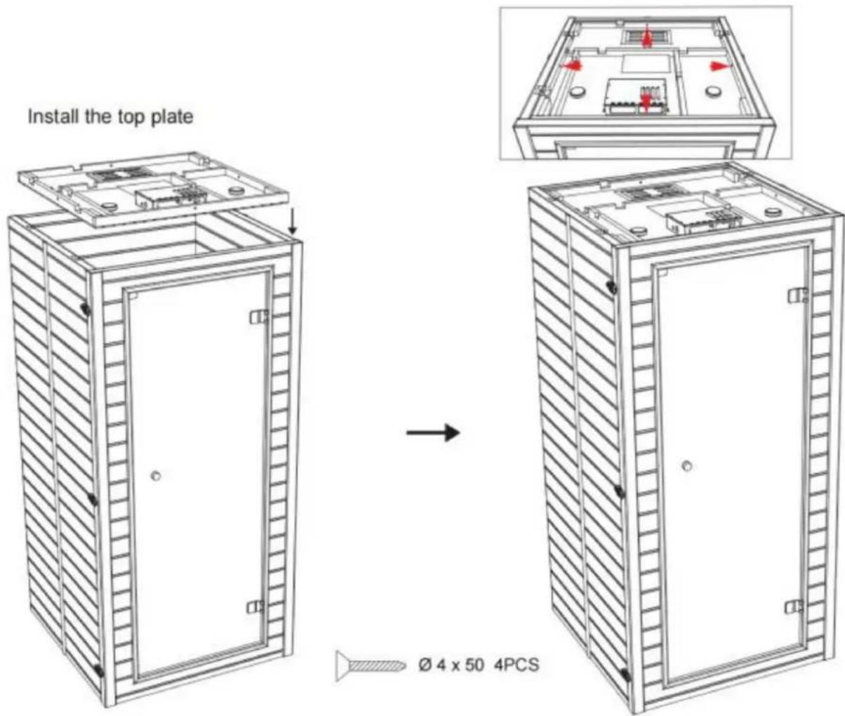
Step 8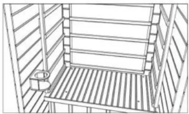
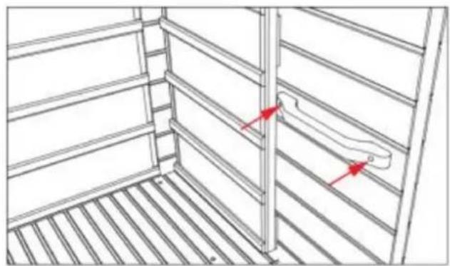
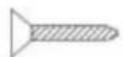
∅ 3 × 35 2PCS
Step 9
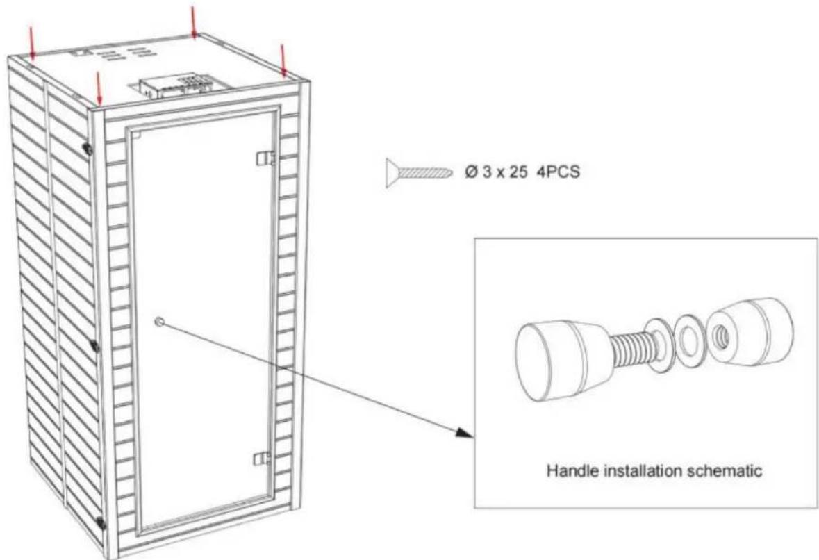
Operation
1. Precautions
Maintenance
electronics www.vevor.com/support
VEVOR®
TOUGH TOOLS, HALF PRICE
Install the left and right side panels:
The left and right side panels are fixed to the rear panel through a buckle connection.
![graph TD A["Outer buckle installation method"] --> B["Step 1: External buckle assembly"] B --> C["Step 2: Rear assembly with circular components"] C --> D["Step 3: Final mounting bracket assembly"] D --> E["Step 4: Final mounting bracket assembly with ring and bolt holes"]](/content/2026/04/734563/images/317ebf9d0db6155bef1ea2a0af09c8673823ffacae51db842a958b7b621a6e81.jpg)
Step 4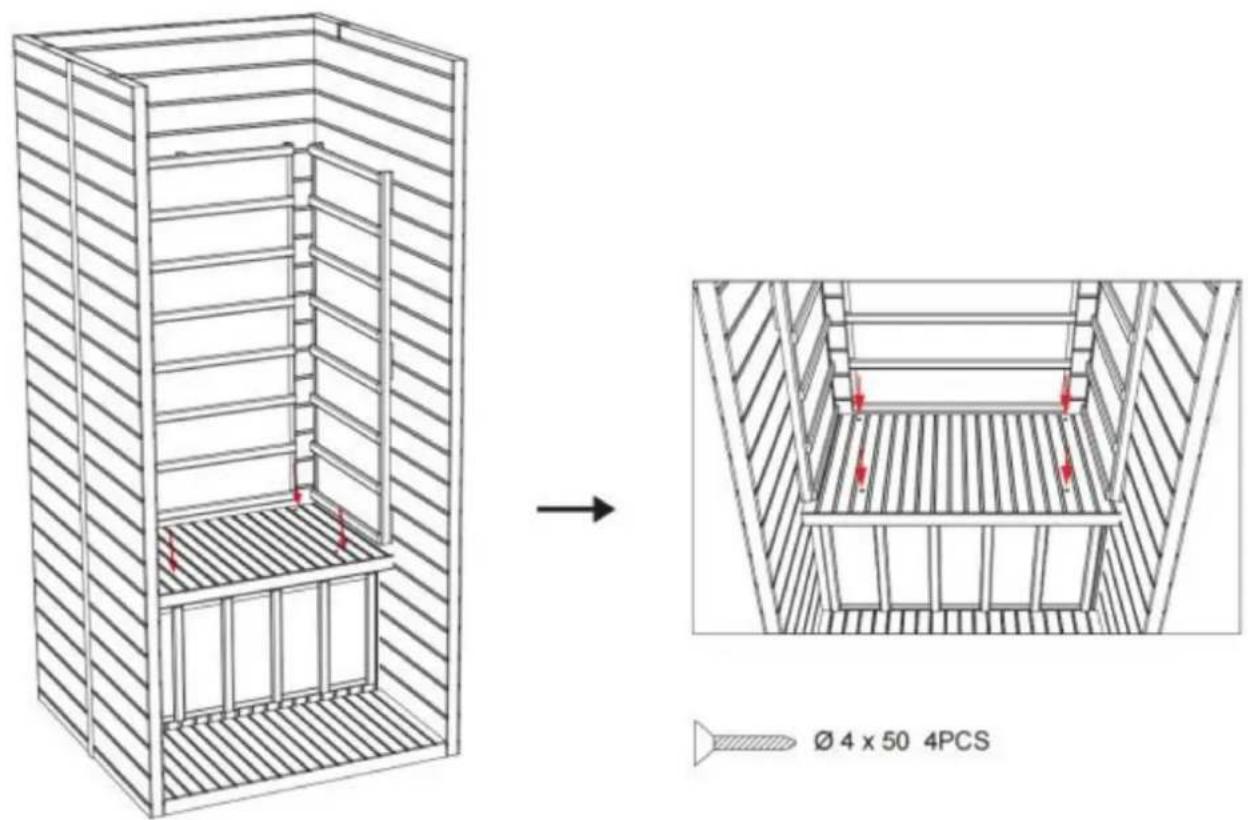
Step 5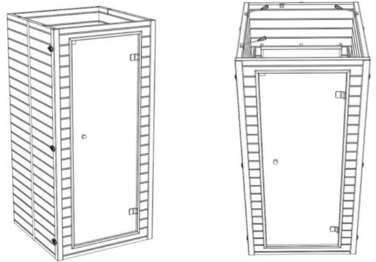
Step 6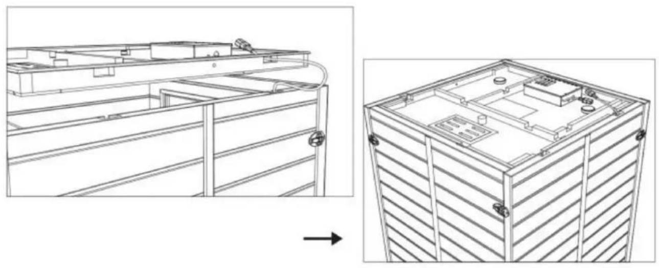
Step 7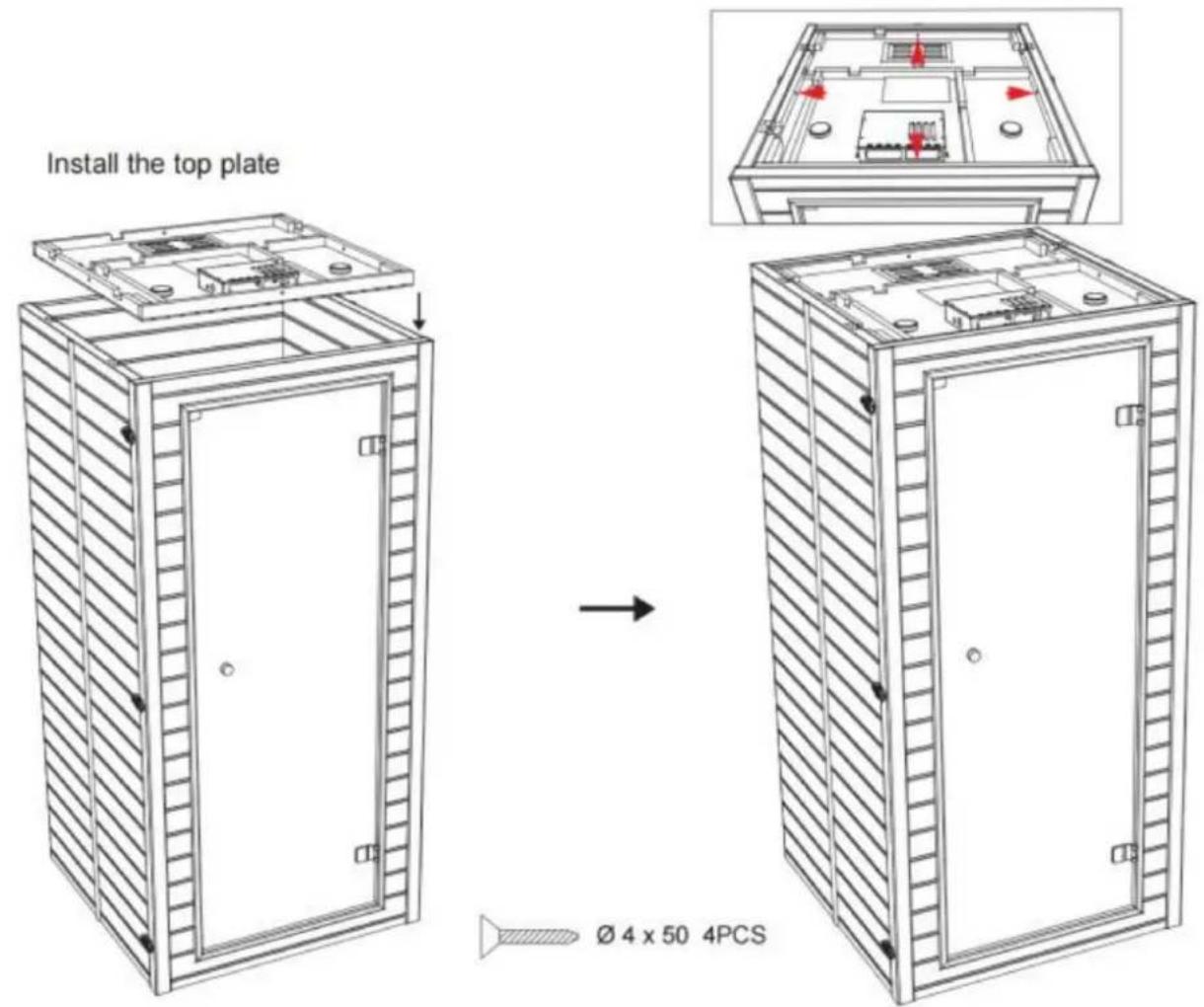
Step 8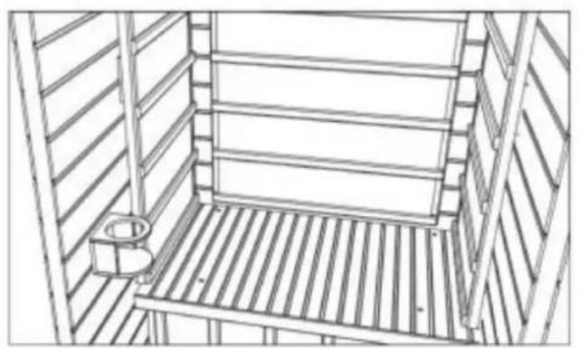
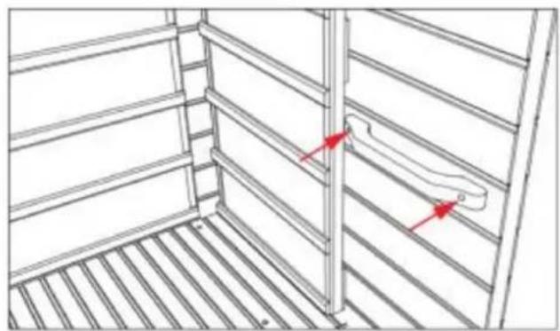
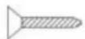
∅ 3 × 35 2PCS
Step 9
Operation
- Precautions
Maintenance
NEED HELP? CONTACT US!
Install the left and right side panels:
The left and right side panels are fixed to the rear panel through a buckle connection.
![graph TD A["Outer buckle installation method"] --> B["Step 1: External buckle assembly"] B --> C["Step 2: Rear assembly with ring and bolt holes"] C --> D["Step 3: Final mounting bracket assembly"] D --> E["Step 4: Final mounting bracket assembly with ring and bolt holes"]](/content/2026/04/734563/images/4b407a89db20d8ccdf8d7602fdbbef90b1c129577787dc88f09c31b53d32e6c5.jpg)
Step 4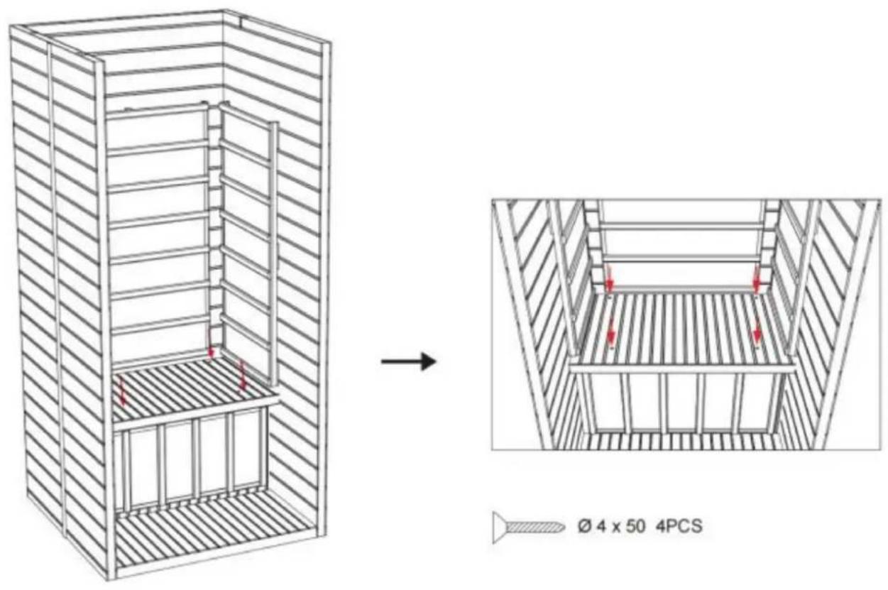
Step 5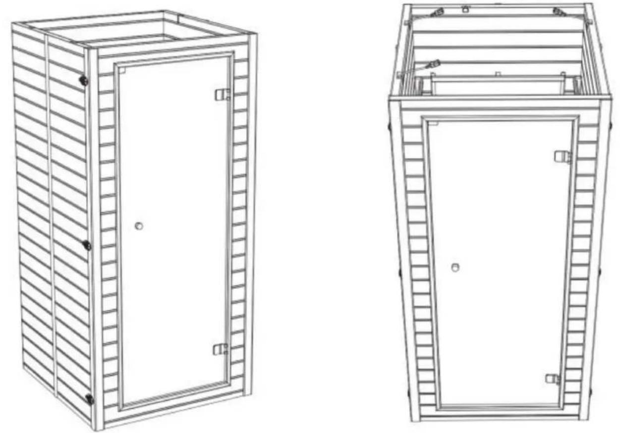
Step 6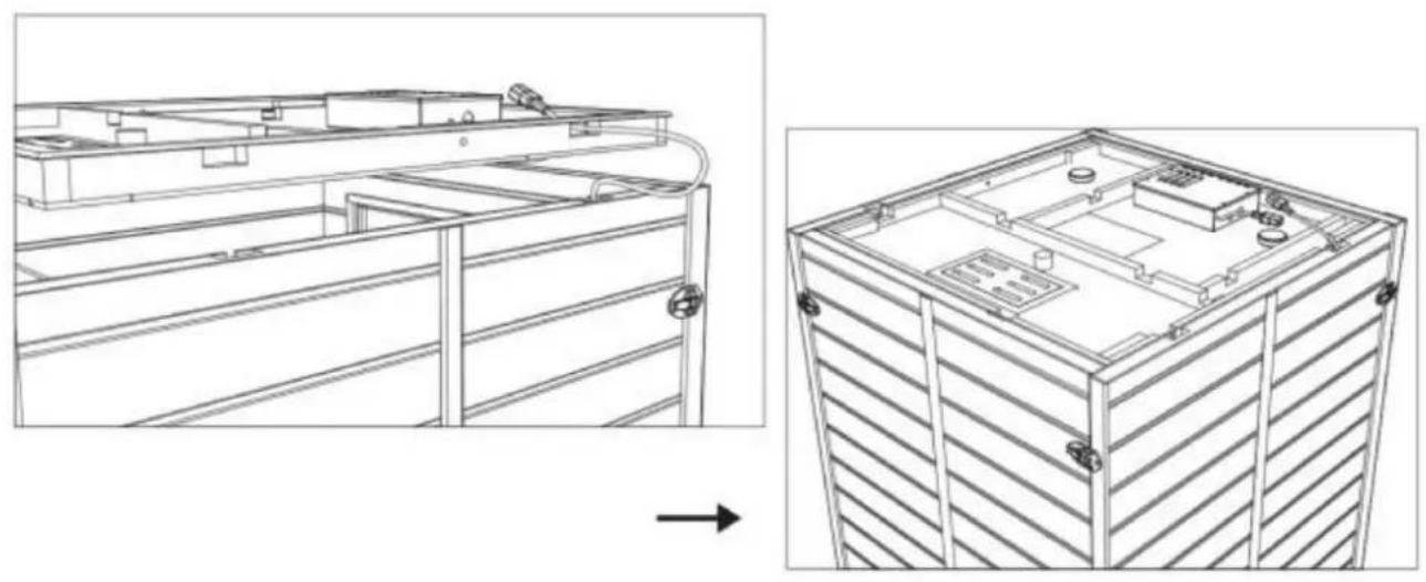
Step 7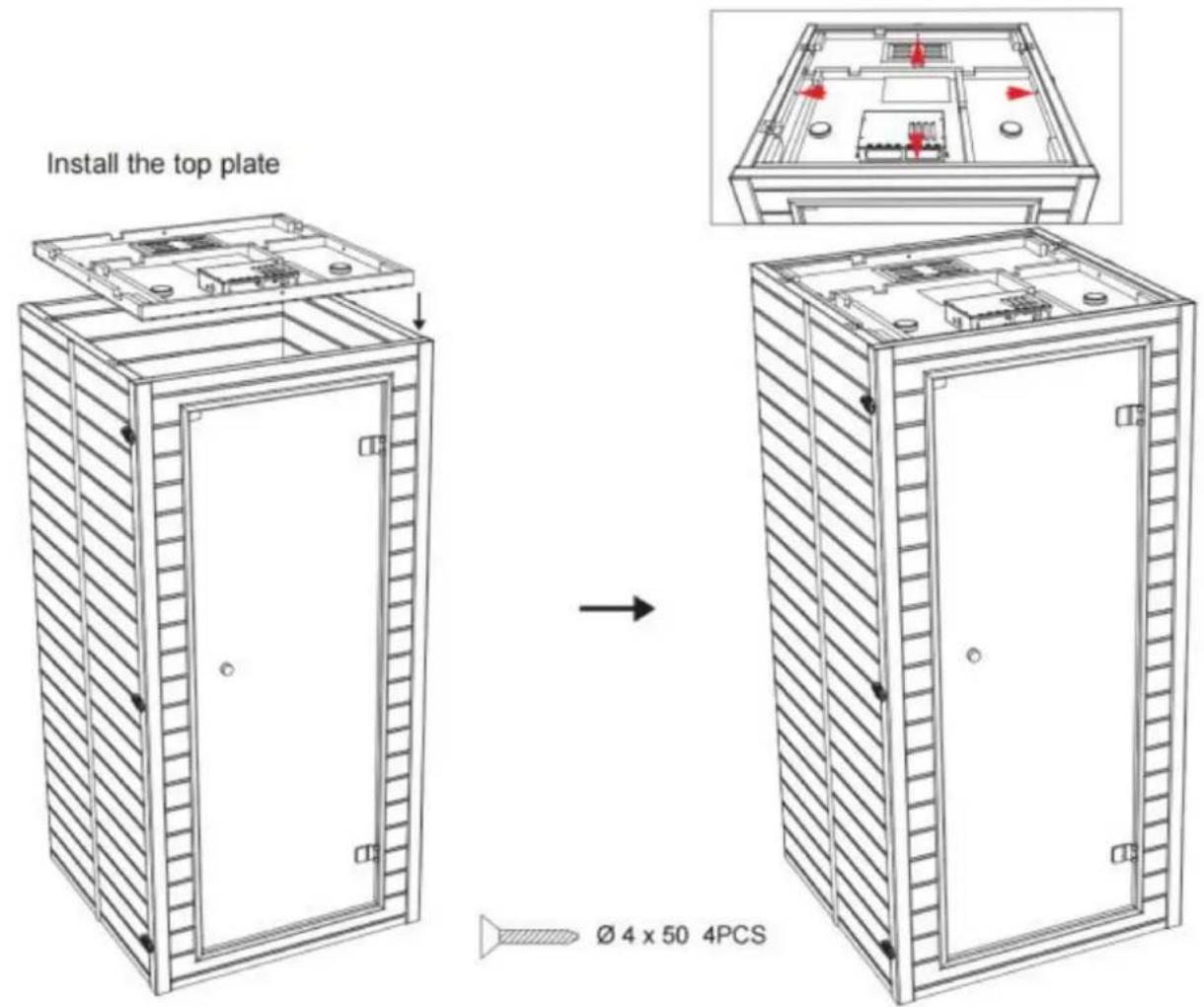
Step 8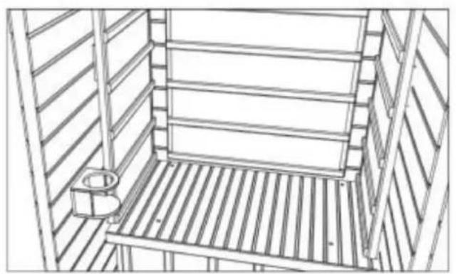
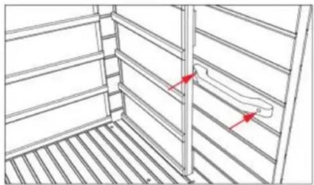
∅ 3 × 35 2PCS
Step 9
Operation
- Precautions
Machine Translated by Google
Maintenance
www.vevor.com/support
VEVOR®
TOUGH TOOLS, HALF PRICE
Technical support and e-warranty certificate www.vevor.com/support
WOOD SAUNA
MODEL: FRB-1M3
NEED HELP? CONTACT US!
| 1 | Stofkap *1 | 5 | Linkerbord *1 | 7 | Bank *1 |
| 2 | Bovenste plank *1 | 5 | Rechterbord *1 | 8 | Voorbord bank *1 |
| 3 | Achterbord *1 | 6 | Voorbord *1 Onderplank | *19 |

| Model | Vermogen (W) | Spanning (V) | Frequentie (Hz) 50 | Stekkertype |
| FRB-1M3 | 1400 | Wisselstroom 220-240 | 50 | Europese norm |
| Wisselstroom 220-240 | 60 | Niet standaard | ||
| Wisselstroom 120 | Amerikaanse standaard |
INSTALLATION PROCEDURE
CAUTION:
Install the left and right side panels:
The left and right side panels are fixed to the rear panel through a buckle connection.
![graph TD A["Outer buckle installation method"] --> B["Step 1: External buckle assembly"] B --> C["Step 2: Rear assembly with ring and bolt holes"] C --> D["Step 3: Final mounting bracket assembly"] D --> E["Step 4: Final mounting bracket assembly with ring and bolt holes"]](/content/2026/04/734563/images/62ea85c8e3874d3d100537d66598fb507f14d52b26e0d5291cbb26f8d39c5b85.jpg)
Step 4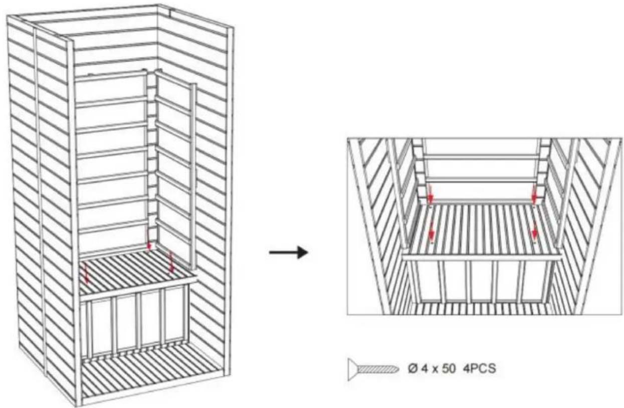
Step 5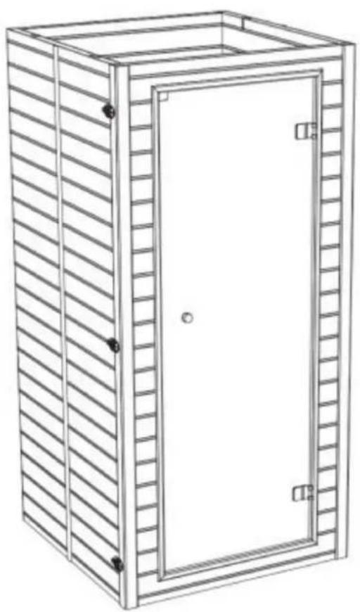
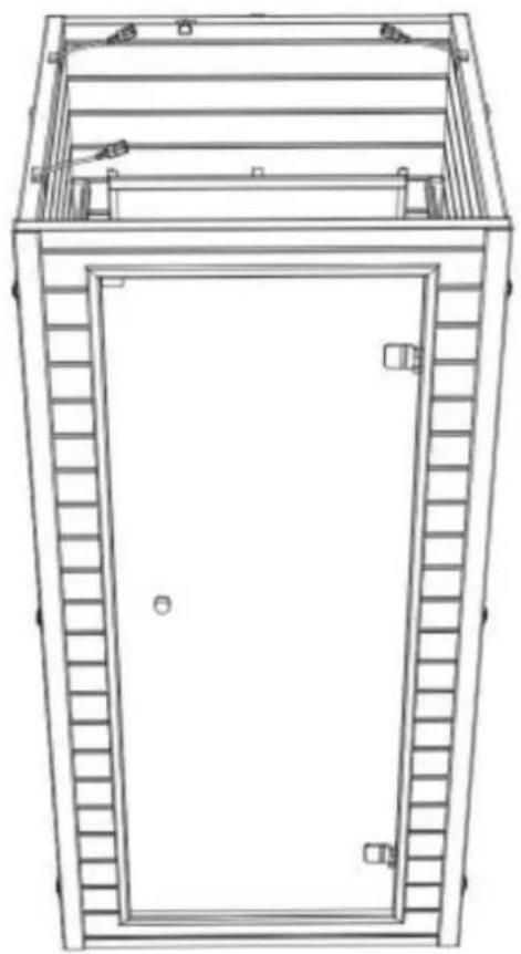
Step 6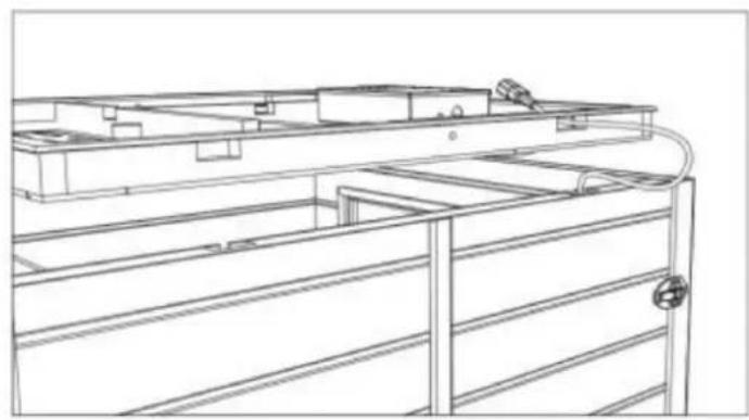
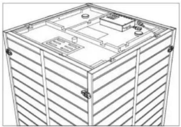
Step 7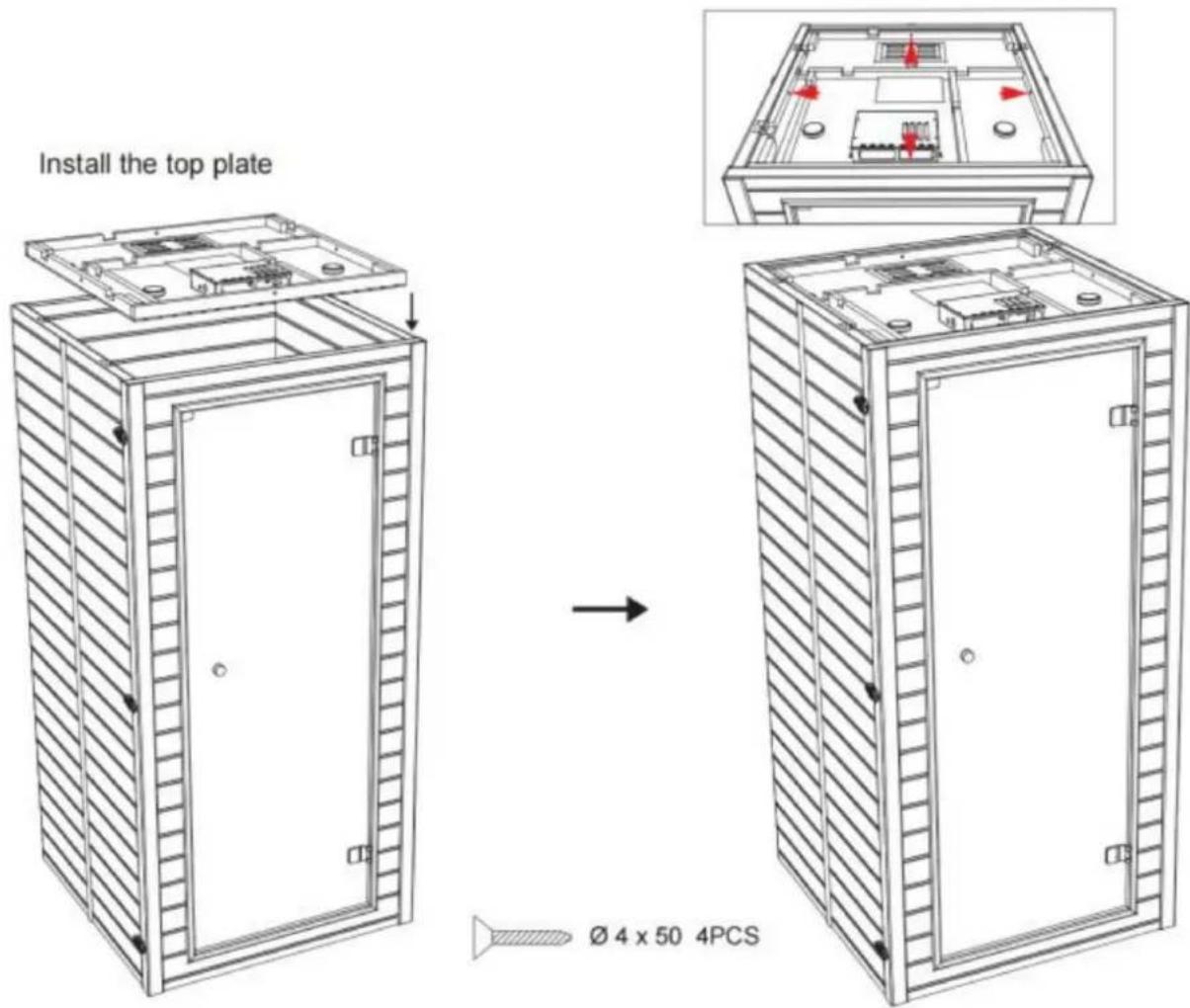
Step 8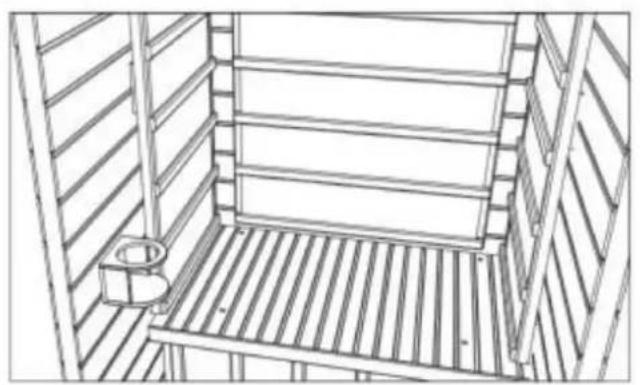
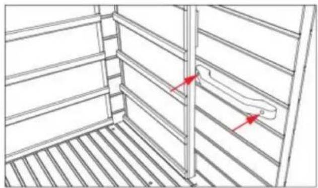
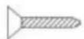
∅ 3 × 35 2PCS
Step 9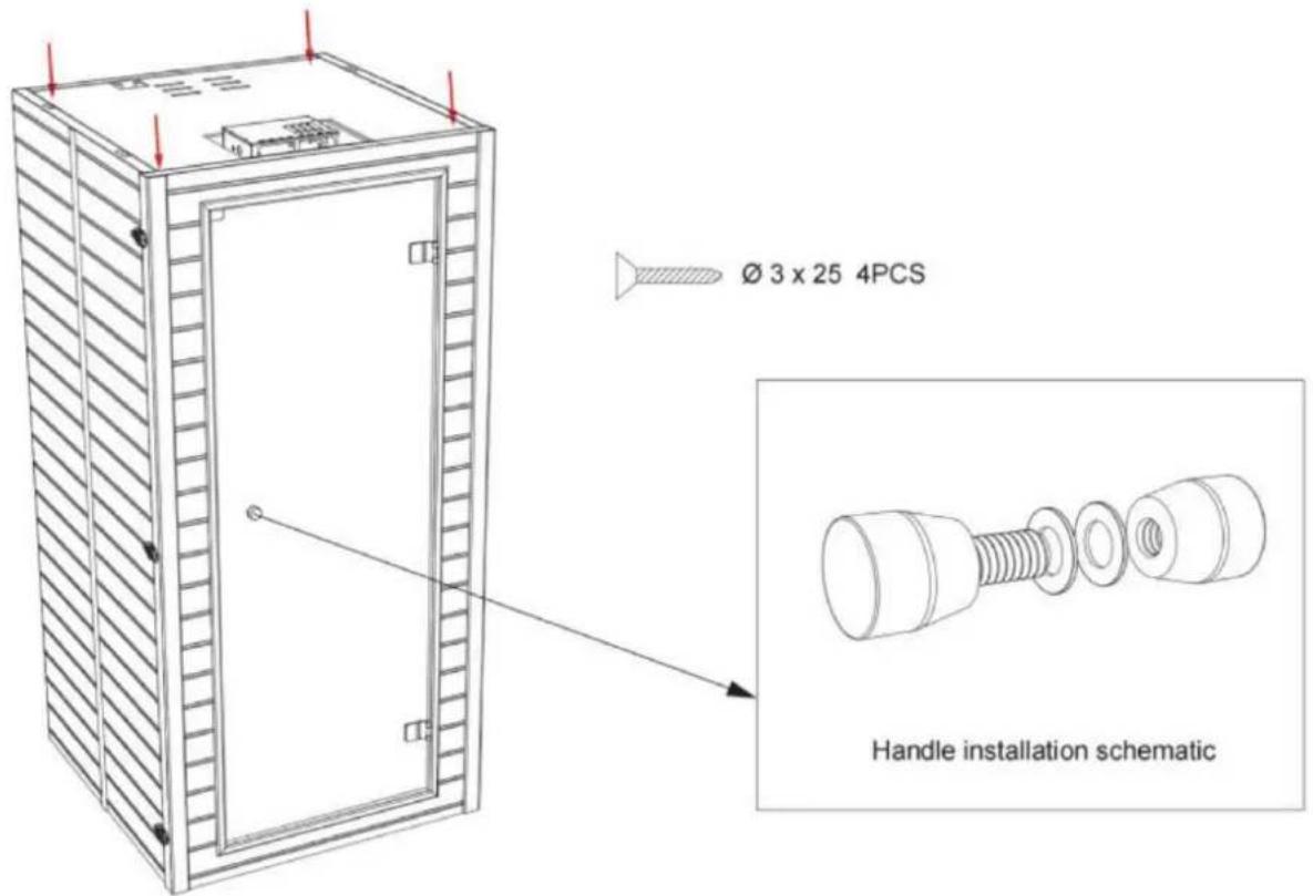
Operation
Maintenance
NEED HELP? CONTACT US!
Install the left and right side panels:
The left and right side panels are fixed to the rear panel through a buckle connection.
![graph TD A["Outer buckle installation method"] --> B["Step 1: External buckle assembly"] B --> C["Step 2: Rear assembly with circular components"] C --> D["Step 3: Final mounting bracket assembly"] D --> E["Step 4: Final mounting bracket assembly with ring and bolt holes"]](/content/2026/04/734563/images/f338f5017fab47f863150ac3814b1139bcb01e9276bff7b3ce5172d00e6b8975.jpg)
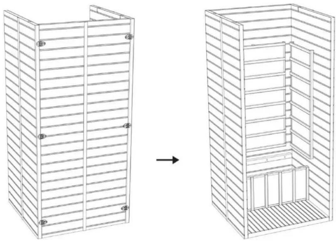
Step 4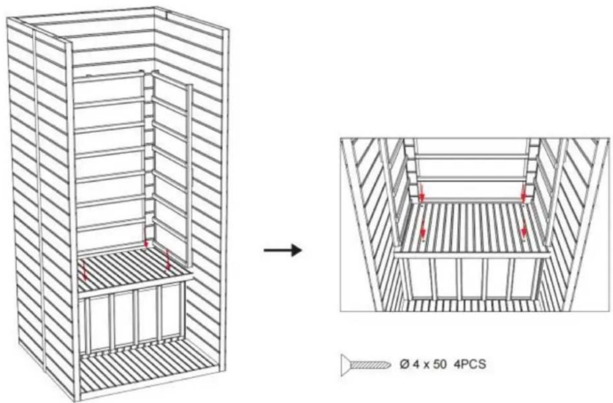
Step 5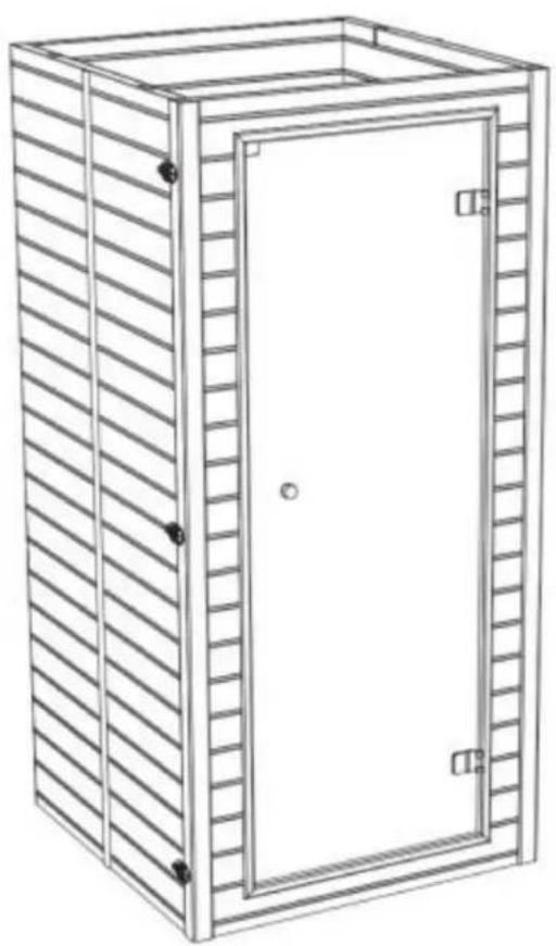
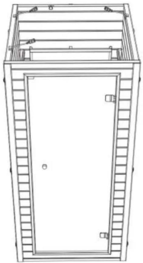
Step 6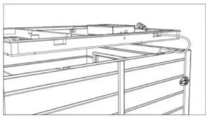
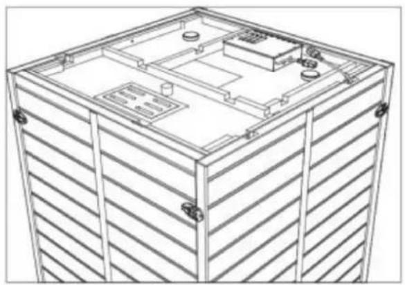
Step 7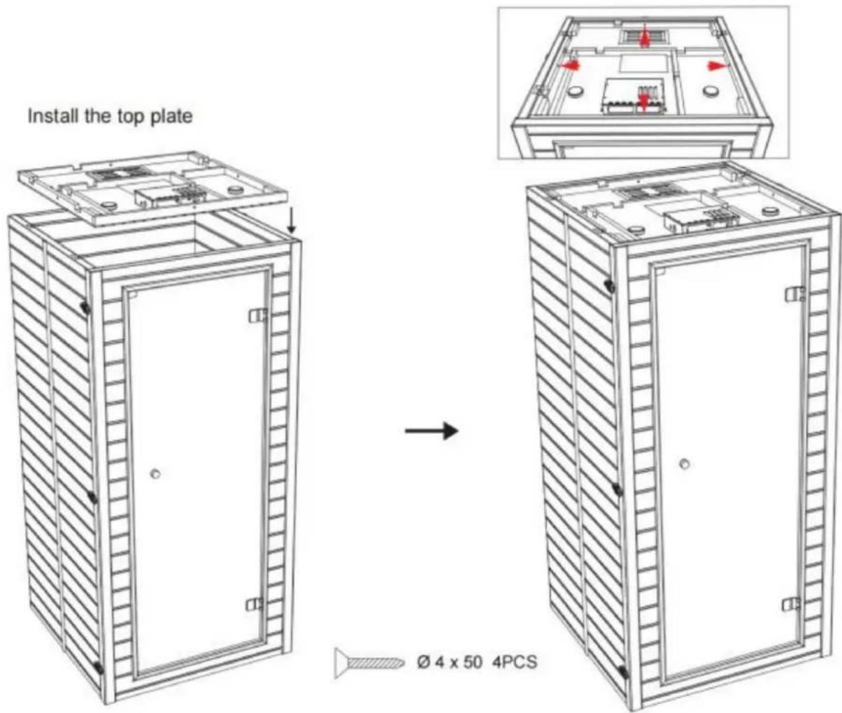
Step 8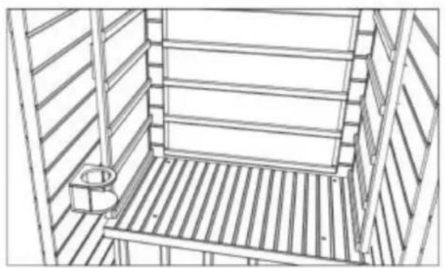
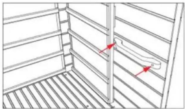
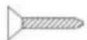
∅ 3 × 35 2PCS
Step 9
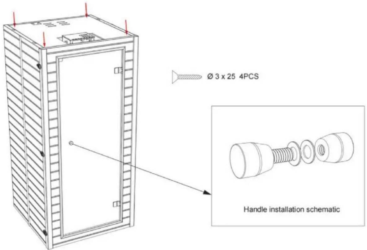
Drift
Maintenance
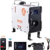
Brand : Vevor
Model : FRB-1M3
Category : Heating