
RC-25 - Electric cutting tool Vevor - Free user manual and instructions
Find the device manual for free RC-25 Vevor in PDF.

| Product Type | Hydraulic Electric Rebar Cutter |
| Brand | Vevor |
| Model | RC-25 |
| Power | 1700 W |
| Power Supply Voltage | AC 220-240 V 50 Hz or 120 V 60 Hz (depending on version) |
| Maximum Cutting Diameter | 25 mm |
| Minimum Cutting Diameter | 5 mm |
| Cutting Speed | ≤ 4 seconds |
| Gross Weight | 31.33 kg |
| Net Weight | 32.13 kg |
| Hydraulic Oil Type | ISO VG46 hydraulic oil (e.g., Shell Tellus 46) |
| Oil Reservoir Capacity | Full up to the edge of the filler hole |
| Number of Cutting Edges per Blade | 4 (rotatable to use a new edge) |
| Carbon Brush Lifespan | Approximately 200 hours |
| Maximum Oil Temperature | 70°C (158°F) – beyond this, power drops |
| Required Safety Equipment | Safety goggles, face shield, gloves, fitted clothing |
| Allowed Materials | Concrete reinforcing bars only |
| Oil Change Frequency | At least once a year |
| Routine Maintenance | Clean after use, check bolts, monitor oil level |
| Warranty | Electronic warranty certificate at www.vevor.com/support |
Frequently Asked Questions - RC-25 Vevor
User questions about RC-25 Vevor
0 question about this device. Answer the ones you know or ask your own.
Ask a new question about this device
Download the instructions for your Electric cutting tool in PDF format for free! Find your manual RC-25 - Vevor and take your electronic device back in hand. On this page are published all the documents necessary for the use of your device. RC-25 by Vevor.
USER MANUAL RC-25 Vevor
Technical Support and E-Warranty Certificate www.vevor.com/support
ELECTRIC REBAR CUTTER
MODEL:RC-16/RC-25/RC-20/RC-22
We continue to be committed to provide you tools with competitive price. "Save Half", "Half Price" or any other similar expressions used by us only represent estimate of savings you might benefit from buying certain tools with us compared top brands and does not necessarily mean to cover all categories of tools offered are kindly reminded to verify carefully when you are placing an order with us actually saving half in comparison with the top major brands.
MODEL:RC-16/RC-25/RC-20/RC-22
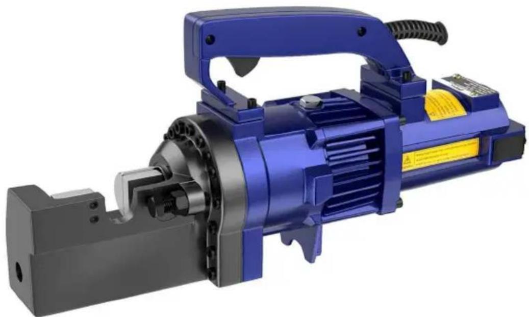
natural_image
3D rendering of a blue electric motor with attached black housing and yellow control panel (no visible text or symbols)NEED HELP? CONTACT US!
Have product questions? Need technical support? Please feel fr contact us:
Technical Support and E-Warranty Certificate www.vevor.com/support
This is the original instruction, please read all manual instruction carefully before operating. VEVOR reserves a clear interpretation user manual. The appearance of the product shall be subject to product you received. Please forgive us that we won't inform you there are any technology or software updates on our product.
SAFETY INSTRUCTIONS
Usage
Use rebar cutters on concrete re-forcing bars only.
Restrict use to designated materials
There is always a chance that the cut end may shoot out, especially than 30cm in length. Exceeding designated material specifications great increases this risk and will also damage the tool. Do not attempt to rebars. Harder, thicker or thinner than those specified.
Use eye protection
Wear safety goggles , safety glassed with side shields or a face shield when using cutter.
Provide safety barriers
Erect safety screens to protect co-workers from possible flying ends. If safety screen under the rebar when working in high places.
Exercise proper control
Hold cutter firmly and maintain proper footing and balance. Do not over-reach when working in high place, secure cutter to scaffolding safety rope. Check that power cord is not fouled and keep cord awa sharp edges and heat. Check that all adjusting wrenches have been removed before using cutter.
Guard Against electric shock
To avoid possible electric shock, do not handle cutter with wet hands use cutter in the rain or damp places. Be aware of all power lines, circuits and other hazards that may be contacted , especially those th below the surface or otherwise hidden from view .
Unplug tool
Disconnect cutter from outlet when not in use and before cleaning, adjusting or servicing. Do not disconnect plug from outlet by pulling the cord. Always check that the switch lock if OFF before plugging in.
Beware of environment
Do not use cutter in the presence of flammable materials (e.g. Paint, thinner, petroleum products, adhesives).
Do not use cutter in a possibly lighted and clear of obstructions. Op should at all times have an unobstructed view of the cutter, rebar and surrounding area.
Wear proper apparel
Do not wear loose clothes, dangling objects or jewellery. Restrain long. The use of a safety-helmet and rubber soled boots is recommended safety gloves are worn, be especially careful that gloves does not get caught in moving parts.
Keep visitors aways
Keep all visitors at a safe distance from the work area for their own protection and to prevent distraction of the operator.
Maintain cutter with care
Inspect cutter before each application. Faulty or loose cutter blocks could result in personal injury. Keep handle dry, clean and free from oil and grease. Keep housing and piston free of dirt and iron filings. Check screws or bolts are loose or missing. Following instruction for maintenance. Inspect switch, cord, plug and any extension cable at rest intervals.
Store carefully
When not in use, store cutter and accessories in dry place where th be accessed by unauthorized person.
PARAMETER LIST
| Model | RC-16 | RC-25 | RC-20 | RC-22 |
| Wattage(W) | 1000 | 1700 | 1000 | 1350 |
| G.W.(kg) | 12.34 | 31.33 | 18.15 | 14.4 |
| N.W.(kg) | 12.84 | 32.13 | 18.75 | 14.9 |
| Cutting speed | ≤2.5s | ≤4S | ≤3s | ≤3.5s |
| Max Rebar | 16mm | 25mm | 20mm | 22mm |
| Min Rebar | 4mm | 5mm | 4mm | 4mm |
Note: There are two versions of the voltage of the above product m respectively, AC220-240V 50Hz and 120V 60Hz, please see the name information of the product.
INSTRUCTIONS
Caution: Indicates hazard that could result in minor personal injury or product damage.
Care: Indicates hazard that will result in product damage.
Pre-use checks
Check oil level.
Check condition of cutter blocks and tightness of cutter block bolts.
Caution: Using loose or cracked cutter blocks may result in injury to operators as well as damage to unit.
Check that the power source is appropriate for the cutter.
Care: If voltage is too high, the motor will burn out. If the voltage insufficient power will be generated. Never use DC current.
Check that power supply is properly earthed.
Caution: Failure to earth power supply may result in electric shock to operator.
Check that cord is undamaged and that plug is not loose.
Caution: Cut or abraded covering could result in a short and electric to operator.
If an extension cable is to be used, make sure that it is undamaged that it is the proper thickness for the length.
| Cable size Cable length | 110V | 230V |
| AWG | Normalization size | |
| Up to 10 m | 16 | 1.0 mm^2 |
| Up to 15 m | 14 | 1.25 mm^2 |
| Up to 30 m | 10 | 1.5 mm^2 |
Warm-up
In cold weather, warm up unit for 30-60 seconds so that the hydra reaches the proper viscosity. Pull trigger-switch to extend piston and release when it has reached its full stroke, Repeat 15-20 times.
Stopper adjustment
The correct position during cutting must be properly set for each size rebar before making a cut.
- Screw in stopper to provide sufficient clearance for rebar.
- Insert rebar fully into U-shaped support. Make sure that rebar is res on the base of the stopper.
- Keeping rebar at right angels (90°) to front cutter block, screw out stopper until it is just touching the rebar. Once set, the stoofer need further adjustment while cutting rebar of the same diameter, but must re-set for a different size rebar.
Caution: Failure to correctly set the stopper will result in excessive w cutter block and may cause cut end to fly out.
Cutting
- Insert rebar between stopper and front cutter block, making sure that properly seated in U-shaped support.
- Pull trigger -switch and keep depressed while piston advances and is cut. ( If switch is released at an intermediate point, piston will stop
- When cut is completed, release switch. Piston retracts automatically. (Note that switch can't be re-activated until piston has fully retracted.)
Points of attention
- Be especially careful when cutting off short lengths (30cm or less) cut end tends to fly out.
Caution: Flying ends are a hazard to all personnel in the vicinity. Er safety screens.
- Do not cover air vents.
Care: If events are covered, motor will overheat and may burn out.
-
If hydraulic oil exceeds 70 ° (158 F) in temperature, power will drop. Allow until to cool before resuming operation. (Be particularly careful in summer, when the aluminum pump case heats up quicker.)
-
If a drop in power is observed and motor is unusually hot, check brush.
-
If piston should ever fail to retract completely, push rear cutter bloc backwards to manually retract piton.
Caution: Use a rebar or flat metal bar for this purpose. Never push block with any part of the hand, even if gloved.
Once piston has been retracted, pull trigger-switch long enough to p advance piston. Unplug unit. And check piston and housing for accumulated dust iron filings that may be jamming the piston. After cleaning, piston still does not automatically retract when fully extended piston itself may be damaged. Return the unit to an authorized agent repair.
Cutter blocks
Before using, always check that the two bolts on each cutter block a properly tightened. Using a loose block will result in damage to block housing. Also check condition of cutter blocks. If either cutting edge i or chipped, remove retaining bolts and rotate both blocks so that two edges come into use. Replace and tighten bolts (each block has four cutting edges)
When all four cutting edges have been used or if either block is created otherwise damaged, replace both block.
Caution: A loose or cracked block may result in injury to operator.
Cleaning
Cleaning cutter after use.
Caution: Wear gloves to protect hands from metal splinters. Do not use air-gun, blasting with air can cause metal filing and/or dust to get into and respiratory system.
-
Disconnect unit.
-
Wipe or brush away all dirt and metal filings. Pay particular attention the lower half of the piston, where dirt is more easily accumulated.
Oil-level check
As the cutters are hydraulically operated, the oil level must be checked frequent intervals, preferably every day. Failure to maintain the oil at proper level results in a drop in pressure and loss of cutting power.
Caution: Hydraulic oil is highly flammable. Keep away from sparks ar naked flame. Do not smoke.
Caution: Hydraulic oil may cause inflammation of the eyes and skin. ingested, it will cause diarrhoea and vomiting.
In case of eye contact, rinse in clean water for at least 15 minutes consult a physician. In case of skin contact, wash thoroughly with soap water.
In case of ingestion, consult a physician immediately. Do not deliberate induce vomiting.
-
Oil should be warm but not hot. Warm up unit if cold.
-
Adjust stopper and make three or four cuts, noting exactly at what the rebar is actually breaking.
-
Pinch a short piece of rebar, stopping just before it breaks off. Unp from power source.
-
With partially severed rebar in place, turn unit over so that oil-plug uppermost. (If unit is hot, allow to cool down.)
-
Remove oil-plug and seal-washer (packing)
Caution: Never remove oil-plug when unit is hot or oil will spurt out. 6.check that oil is level with bottom of plug hole. (i.e. That pump can to the brim). If oil level is too low, top up with 20-weight hydraulic
anti-foam and anti-abrasion properties. (ISO viscosity grade VG46. E.g. Shell oil tellus 46, mobil oil DTE-25 OR Esso uni power SQ46.)
- After topping up, extract air from system. Gently tilt cutter lengthwise return it to a level position. Top up again and tilt in the opposite di Repeat this process until all air has been extracted.
Care: Cutter can't function properly if oil contains air bubbles.
- Replace seal washer (packing) and plug. Connect cutter to power so and completely serve rebar.
Oil change
The hydraulic oil should be changed at least once a year. Sooner if appears dirty.
- Unplug unit from power source. Remove oil plug and packing. Turn over and drain oil into a suitable receptacle. When oil ceases to draw tilt unit to rear so that oil trapped in the piston housing can run out housing is empty, tilt unit in the opposite direction to empty the residue the pump case.
- With drain-hole uppermost, slowly fill the unit with fresh oil. Replace and lightly tighten. Connect unit to power source and advance piston three times. Unplug unit and remove oil-plug. Top up oil level and plug.
- Finally follow procedure for oil level check.
Note: Dispose of hydraulic oil in accordance with local regulations. Do pour into the sea, river, lake or drains.
Bolt tightness
Once a week or after every 500 cuts, check the tightness of all bolts especially those securing the housing to the cylinder. Loose bolts will in a loss of power.
Carbon brushes
Inspect the two carbon brushes at least once every two months. (nor brush life is 200 hours.)
Care: Worn brushes will result in power loss, cause the motor to run
and irreparably damage the armature's commutator.
1.Disconnect unit
2.Unscrew both brush caps and pull out carbon brushes.
3. Replace brushes if less than 6 cm in length.
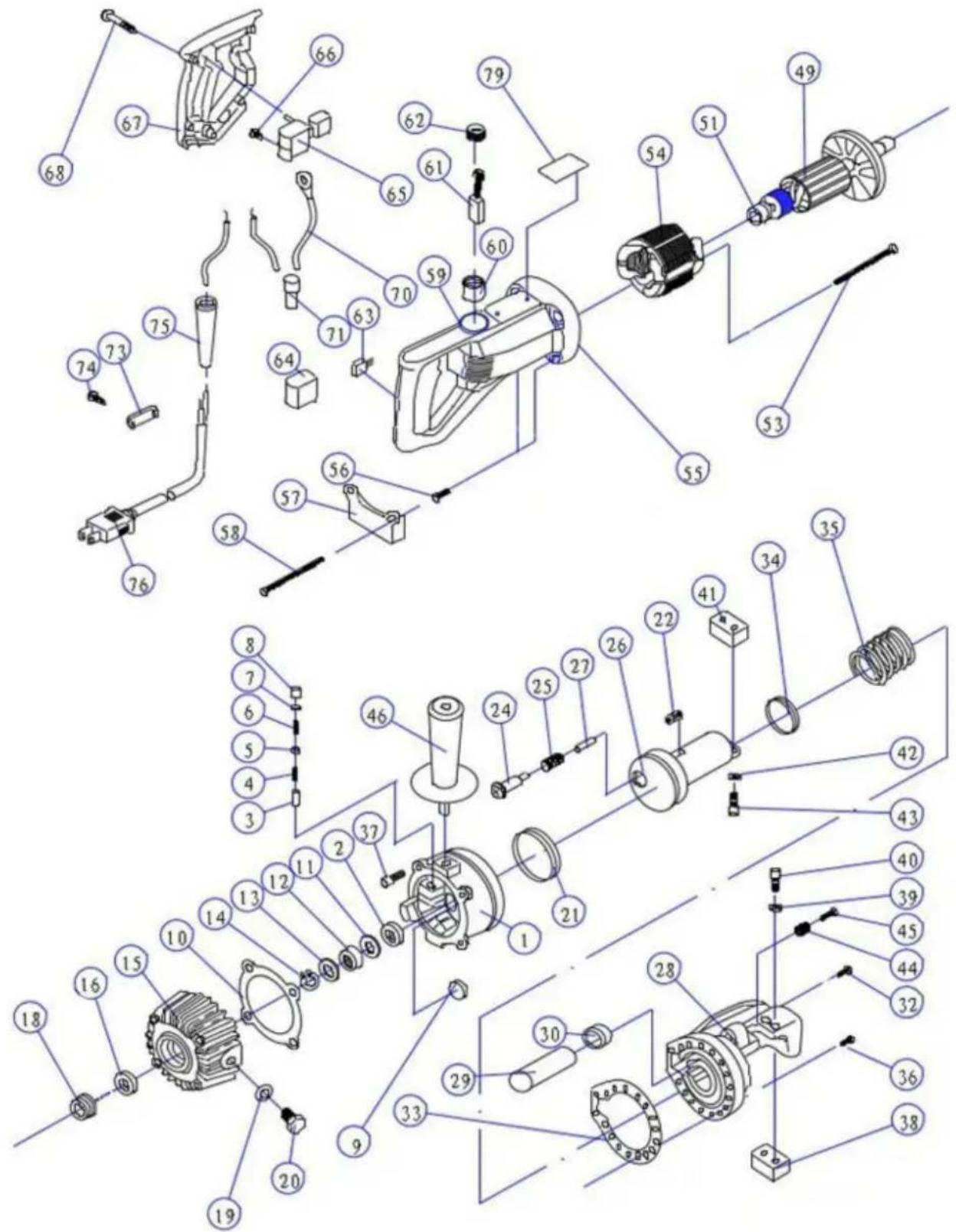
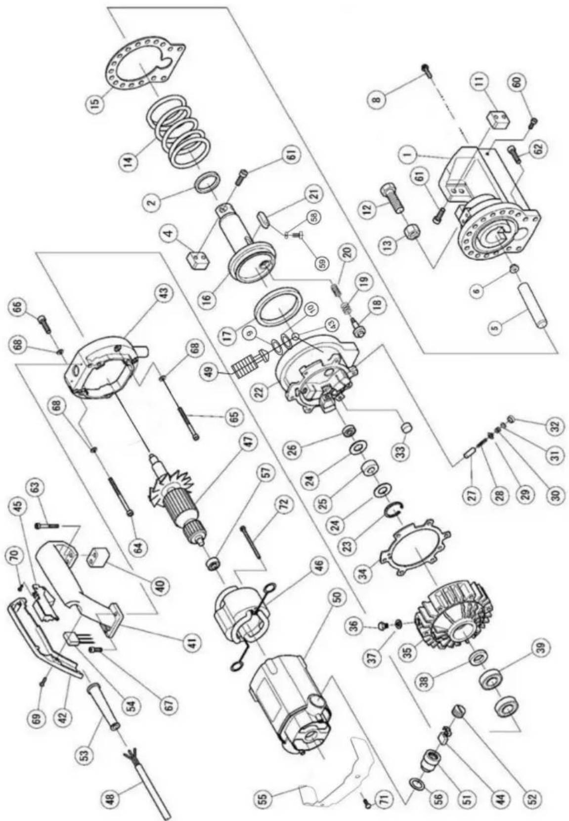
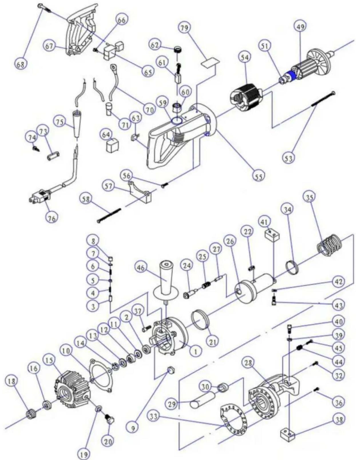
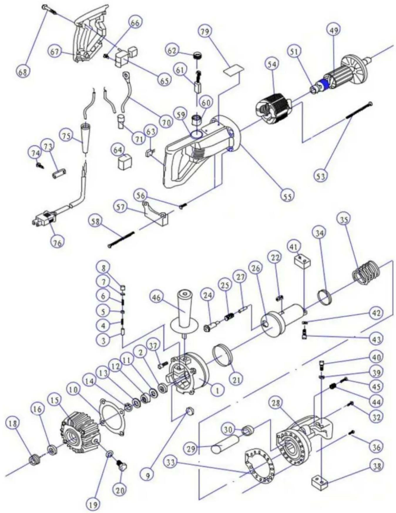
Portable Rebar Cutter Parts List
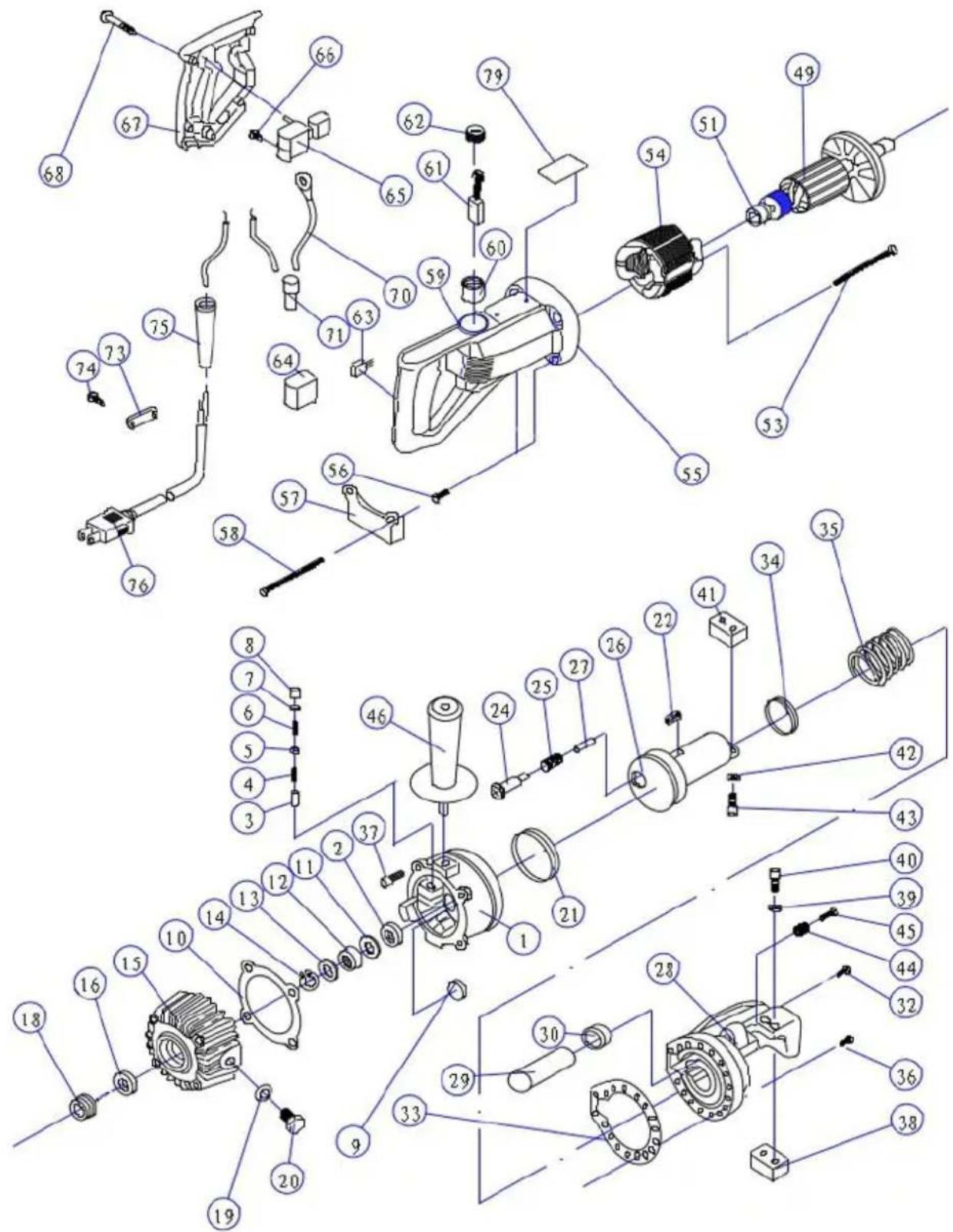
RC-16 Portable Rebar Cutter Parts List
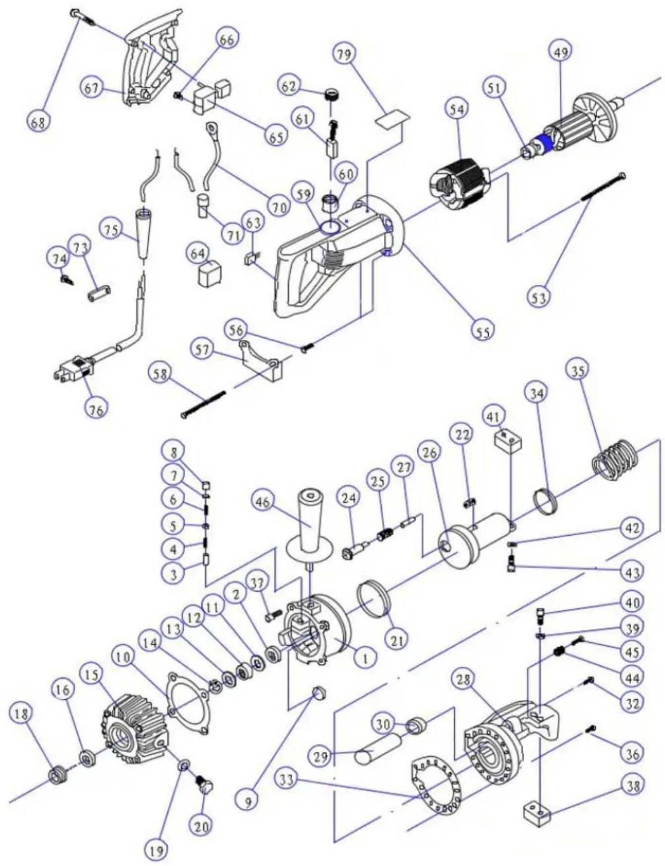
RC-16 PARTS LIST
| NO. | PARTS NAME | NO. | PARTS NAME |
| 1 | CYLINDER | 40 | hexagon socket screw M5 18 |
| 2 | BALL BEARING 698 | 41 | CUTTER BLOCK / BLADE |
| 3 | PISTON | 42 | SPRING WASHER Φ5 |
| 4 | RETURN SPRING | 43 | hexagon socket screw M5×16 |
| 5 | OIL VALVE | 44 | SPRING |
| 6 | VALVE SPRING | 45 | hex socket screw M10×40 |
| 7 | SPRING GUIDE | 46 | HANDLE |
| 8 | PUMP SEAL | 47 | ** |
| 9 | MAGNET FILTER | 48 | ** |
| 10 | GASKET | 49 | ARMATURE |
| 11 | MANGANESE STEEL GASKET | 50 | ** |
| 12 | NEEDLE BEARING 12×24×10 | 51 | BEARING 608 |
| 13 | MANGANESE STEEL GASKET | 52 | ** |
| 14 | SNAP RING | 53 | TAPPING SCREW M4×60 |
| 15 | SNAP RING | 54 | STATOR COIL |
| 16 | PUMP CASE OIL SEAL 15×25×7 | 55 | MOTOR HOUSING |
| 17 | ** | 56 | LOCATING SLEEVE |
| 18 | BEARING 6002 | 57 | FOOT STAND |
| 19 | COMPOUND GASKET Φ10 | 58 | hexagon socket screw M5×85 |
| 20 | HEXAGONAL BOLT M10×16 | 59 | hexagon socket set screw M4×5 |
| 21 | GASKET RING 70×60×6 | 60 | BRUSH HOLDER |
| 22 | PIN 8×25 | 61 | CARBON BRUSH |
| 23 | ** | 62 | BRUSH CAP |
| 24 | RETURN ROD | 63 | CONDENSER |
| 25 | SPRING | 64 | CONDENSER COVER |
| 26 | CUTTER ROD | 65 | SWITCH |
| 27 | SPRING | 66 | RUBBER PUSH BUTTON |
| 28 | CUTTER HEAD | 67 | HOUSING COVER |
| 29 | AIR BAG | 68 | TAPPING SCREW M4x20 |
| 30 | NUT | 69 | ** |
| 31 | ** | 70 | ** |
| 32 | SCREW | 71 | SAFETY CAP |
| 33 | GASKET | 72 | ** |
| 34 | SEAL 40*30*6 | 73 | CORD HOLDER |
| 35 | BIG SPRING | 74 | TAPING SCREW M4x14 |
| 36 | hexagon socket screw M6 x 20 | 75 | CORD ARMOR |
| 37 | hexagon socket screw M6 x 20 | 76 | ELECTRICAL CORD |
| 38 | CUTTER BLOCK / BLAD | 77 | ** |
| 39 | PRING WASHER M5 | 78 | ** |
| 79 | NAME PLATE |
RC-20, RC-22, RC-25
Portable Rebar Cutter Parts List
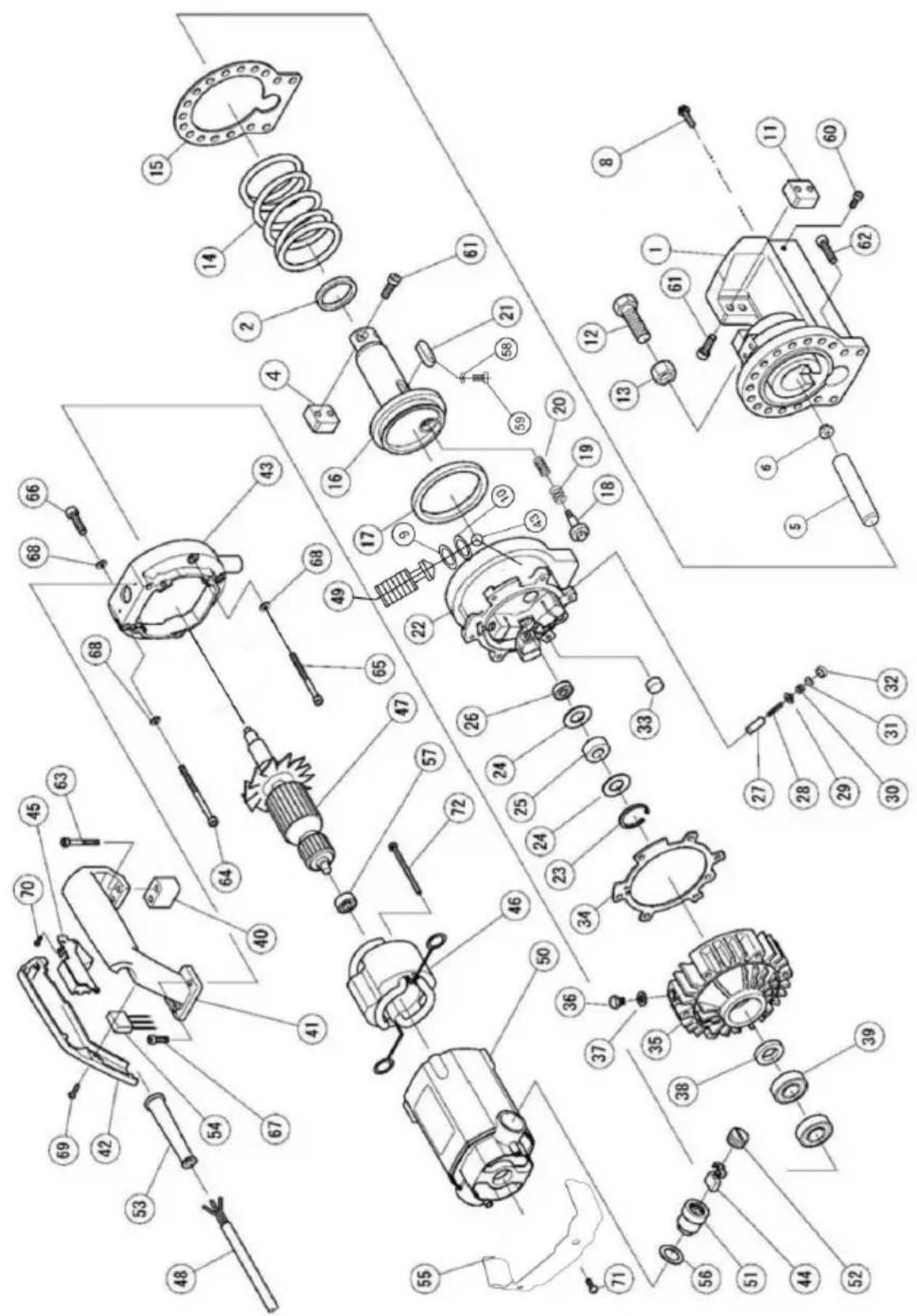
RC-20/RC-22/RC-25 PARTS LIST
| NO. | PARTS NAME | NO. | PARTS NAME |
| 1 | CUTTER HEAD | 40 | CONNECTING BLOCK |
| 2 | GASKET RING 40×50×6 | 41 | HANDLE |
| 3 | ** | 42 | HANDLE COVER |
| 4 | CUTTER BLOCK / BLADE | 43 | PHOTOSPHERE Φ4.763 |
| 5 | AIR BAG | 44 | CARBON BRUSH |
| 6 | NUT | 45 | SWITCH |
| 7 | ** | 46 | STATOR COIL |
| 8 | SCREW | 47 | ARMATURE |
| 9 | O RING | 48 | ELECTRICAL CORD |
| 10 | O RING | 49 | BOLT |
| 11 | CUTTER BLOCK / BLADE | 50 | MOTOR HOUSING |
| 12 | HEXAGONAL SCREW | 51 | CARBON BRUSH HOLDER |
| 13 | NUT | 52 | CARBON BRUSH CAP |
| 14 | BIG SPRING | 53 | CABLE ARMOR |
| 15 | GASKET | 54 | ** |
| 16 | CUTTER ROD | 55 | ** |
| 17 | GASKET RING 80×95×9 | 56 | GUM WASHER |
| 18 | RETURN SHAFT | 57 | BEARING 6200 |
| 19 | SPRING | 58 | WAVE WASHER |
| 20 | SPRING | 59 | BOLT M4*8 |
| 21 | PIN 12×40 | 60 | BOLT M8*25 |
| 22 | CYLINDER | 61 | BOLT M8*30 |
| 23 | SNAP RING | 62 | BOLT M8*30 |
| 24 | MANGANESE STEEL GASKET | 63 | BOLT M6*20 |
| 25 | NEEDLE BEARING 14×30×12 | 64 | BOLT M6*20 |
| 26 | BEARING 609 | 65 | BOLT M6*25 |
| 27 | PISTON | 66 | BOLT M6*50 |
| 28 | SPRING | 67 | BOLT M6*20 |
| 29 | OIL VALVE | 68 | WASHER |
| 30 | SPRING | 69 | BOLT M4*12 |
| 31 | SPRING GUIDE | 70 | BOLT M4*8 |
| 32 | OIL SEAL | 71 | ** |
| 33 | FILTER MAGNET | 72 | BOLT M5*75 |
| 34 | GASKET | 73 | CONNECTING PLATE |
| 35 | PUMP CASE | ||
| 36 | HEXAGONAL SCREW M10×16 | ||
| 37 | COMPOUND GASKET Φ10 | ||
| 38 | OIL SEAL 20×35×8 | ||
| 39 | BEARING 104 |
Manufacturer: Shanghaimuxinmuyeyouxiangongsi
Address: Shuangchenglu 803nong11hao1602A-1609shi, baoshanqu, shanghai 200000 CN.
Imported to AUS: SIHAO PTY LTD. 1 ROKEVA STREETEASTWOOD NSW 2122 Australia
Imported to USA: Sanven Technology Ltd. Suite 250, 9166 Anaheim Place, Rancho Cucamonga, CA 91730
| UK | REP |
YH CONSULTING LIMITED. C/O YH Consultin Limited Office 147, Centurion House, London Road, Staines-upon-Thames, Surrey, TW18 4A>
| EC | REP |
Technical Support and E-Warranty Certificate
www.vevor.com/support
VEVOR®
TOUGH TOOLS, HALF PRICE
natural_image
Blue electric motor with attached black housing and yellow warning label (no visible text or symbols)BESOIN D'AIDE? CONTACTEZ-NOUS!
Portable Rebar Cutter Parts List
LISTE DES PIÈCES RC-16
| NON. | NOM DES PIÈCES | NON. | NOM DES PIÈCES |
| 1 | CYLINDRE | 40 | vis à six pans creux M5 x 18 |
| 2 | ROULEMENT À BILLES 698 | 41 | BLOC DE COUPE / LAME |
| 3 | PISTON | 42 | RONDELLE RESSORT F5 |
| 4 | RESSORT DE RAPPEL | 43 | vis à six pans creux M5×16 |
| 5 | SOUPAPE D'HUILE | 44 | PRINTEMPS |
| 6 | RESSORT DE SOUPAPE | Vis à | six pans creux 45 M10x40 |
| 7 | GUIDE À RESSORT | 46 | POIGNÉE |
| 8 | JOINT DE POMPE | 47 | ** |
| 9 | 48FILTRE MAGNÉTIQUE | ** | |
| dix | JOINT | 49 | ARMATURE |
| 11 | ACIER AU MANGANÈSE JOINT | 50 | ** |
| 12 | ROULEMENT À AIGUILLES 12×24×10 | 51 | ROULEMENT 608 |
| 13 | ACIER AU MANGANÈSE JOINT | 52 | ** |
| 14 | ANNEAU À PRESSION | 53 | VIS TARAUDEUSES M4×60 |
| 15 | ANNEAU À PRESSION | 54 | BOBINE DE STATOR |
| 16 | JOINT D'HUILE DE CARTER DE POMPE 15×25×7 | 55 | CARTER MOTEUR |
| 17 | ** | 56 | MANCHON DE LOCALISATION |
| 18 | ROULEMENT 6002 | 57 | SUPPORT DE PIED |
| 19 | JOINT COMPOSÉ F10 | 58 | vis à six pans creux M5×85 |
| 20 | BOULON HEXAGONALM10×16 | 59 | vis de réglage à six pans creuxM4×5 |
| 21 JOINT D'ÉTANCHÉITÉ 70×60×6 60 | PORTE-BALAIS | ||
| 22 | BROCHE 8×25 | 61 | BROSSE EN CARBONE |
| 23 | ** | 62 | BOUCHON DE BROSSE |
| 24 | TIGE DE RETOUR | 63 | CONDENSEUR |
| 25 | PRINTEMPS | 64 | COUVERCLE DU CONDENSEUR |
| 26 | TIGE DE COUPE | 65 | CHANGER |
| 27 | PRINTEMPS | 66 | BOUTON POUSSOIR EN CAOUTCHOUC |
| 28 | TÊTE DE COUPE | 67 | COUVERCLE DU BOÎTIER |
| 29 | AIRBAG | 68 | VIS TARAUDEUSES M4x20 |
| 30 | NOIX | 69 | ** |
| 31 | ** | 70 | ** |
| 32 | VIS | 71 | CAPUCHON DE SÉCURITÉ |
| 33 | JOINT | 72 | ** |
| 34 | JOINT 40*30*6 | 73 | SUPPORT DE CORDON |
| 35 | GRAND PRINTEMPS | 74 | VIS À RUBAN M4x14 |
| 36 | vis à six pans creux M6x20 | 75 | ARMURE DE CORDON |
| 37 | vis à six pans creux M6x20 | 76 | CORDON ÉLECTRIQUE |
| 38 | BLOC DE COUPE / LAME 77 | ** | |
| 39 | RONDELLE IMPRIMANTE M5 | 78 | ** |
| 79 | PLAQUE SIGNALÉTIQUE | ||
RC-20, RC-22, RC-25
Portable Rebar Cutter Parts List
LISTE DES PIÈCES RC-20/RC-22/RC-25
| NON. | NOM DES PIÈCES | NON. | NOM DES PIÈCES |
| 1 | TÊTE DE COUPE | 40 | BLOC DE CONNEXION |
| 2 | JOINT D'ÉTANCHÉITÉ 40×50×6 | 41 | POIGNÉE |
| 3 | ** | 42 | COUVERCLE DE POIGNÉE |
| 4 | BLOC DE COUPE / LAME | 43 | PHOTOSPHÈRE Φ4.763 |
| 5 | AIRBAG | 44 | BROSSE EN CARBONE |
| 6 | NOIX | 45 | CHANGER |
| 7 | ** | 46 | BOBINE DE STATOR |
| 8 | VIS | 47 | ARMATURE |
| 9 | JOINT TORIQUE | 48 | CORDON ÉLECTRIQUE |
| dix | JOINT TORIQUE | 49 | BOULON |
| 11 | BLOC DE COUPE / LAME | 50 | CARTER MOTEUR |
| 12 | VIS HEXAGONALE | 51 | PORTE-BALAIS EN CHARBON |
| 13 | NOIX | 52 | BOUCHON DE BROSSE DE CHARBON |
| 14 | GRAND PRINTEMPS | 53 | ARMURE DE CÂBLE |
| 15 | JOINT | 54 | ** |
| 16 | TIGE DE COUPE | 55 | ** |
| 17 | JOINT D'ÉTANCHÉITÉ 80×95×9 | 56 | RONDELLE DE GOMME |
| 18 | ARBRE DE RETOUR | 57 | ROULEMENT 6200 |
| 19 | 58 | PRINTEMPS RONDELLE ONDULÉE | |
| 20 | PRINTEMPS | 59 | BOULON M4*8 |
| 21 | BROCHE 12×40 | 60 | BOULON M8*25 |
| 22 | CYLINDRE | 61 | BOULON M8*30 |
| 23 | ANNEAU À PRESSION | 62 | BOULON M8*30 |
| 24 JOINT ACIER AU MANGANÈSE 63 | BOULON M6*20 | ||
| 25 ROULEMENT À AIGUILLES 14×30×12 64 | BOULON M6*20 | ||
| 26 | ROULEMENT 609 | 65 | BOULON M6*25 |
| 27 | PISTON | 66 | BOULON M6*50 |
| 28 | PRINTEMPS | 67 | BOULON M6*20 |
| 29 | SOUPAPE D'HUILE | 68 | MACHINE À LAVER |
| 30 | PRINTEMPS BOULON M4*12 | 69 | |
| 31 | GUIDE À RESSORT | 70 | BOULON M4*8 |
| 32 | JOINT HUILE | 71 | ** |
| 33 | AIMANT DE FILTRE | 72 | BOULON M5*75 |
| 34 | JOINT | 73 | PLAQUE DE RACCORDEMENT |
| 35 | CARTER DE POMPE | ||
| 36 VIS HEXAGONALE M10×16 | |||
| 37 JOINT COMPOSE Φ10 | |||
| 38 | JOINT D'HUILE 20×35×8 | ||
| 39 | ROULEMENT 104 | ||
Fabricant : Shanghaimuxinmuyeyouxiangongsi Adresse :
Shuangchenglu 803nong11hao1602A-1609shi, baoshanqu, shanghai 200000 CN.
Importé en Australie : SIHAO PTY LTD. 1 ROKEVA STREETASTWOOD NSW 2122 Australie
YH CONSULTING LIMITÉE. C/O YH Consulting Limited Bureau 147, Centurion House, London Road, Staines-upon-Thames, Surrey, TW18 4AX

E-CrossStu GmbH
Mainzer Landstr.69,
natural_image
Blue and black industrial electric motor with visible internal components and mounting bracket (no text or symbols)Portable Rebar Cutter Parts List

RC-16 TEILELISTE
RC-20/RC-22/RC-25 TEILELISTE
YH CONSULTING LIMITED. C/O YH Consulting Limited Office 147, Centurion House, London Road, Staines-upon-Thames, Surrey, TW18 4AX

www.vevor.com/support
VEVOR®
TOUGH TOOLS, HALF PRICE
natural_image
Blue and black industrial electric motor with visible shaft, housing, and mounting bracket (no text or symbols)HO BISOGNO DI AIUTO? CONTATTACI!
Shell oil tellus 46, mobil oil DTE-25 O Esso uni power SQ46.)
Portable Rebar Cutter Parts List

ELENCO PARTI RC-16
| NO. | NOME DELLE PARTI | NO. | NOME DELLE PARTI |
| 1 | CILINDRO | 40 | vite a esagono incassato M5 x 18 |
| 2 | CUSCINETTO A SFERE 698 | 41 | BLOCCO LAMA/LAMA |
| 3 | PISTONE | 42 | RONDELLA MOLLA ŷ5 |
| 4 | MOLLA DI RITORNO | 43 | vite a esagono incassato M5x16 |
| 5 | VALVOLA DELL'OLIO | 44 | PRIMAVERA |
| 6 | MOLLA VALVOLA | 45 | vite cava esagonale M10x40 |
| 7 | GUIDA MOLLA | 46 | MANIGLIA |
| 8 | TENUTA DELLA POMPA | 47 | ** |
| 9 | FILTRO MAGNETICO | 48 | ** |
| 10 | GUARNIZIONE | 49 | ARMATURA |
| 11 | ACCIAIO AL MANGANESE GUARNIZIONE | 50 | ** |
| 12 | CUSCINETTO AD AGHI 12x24x10 | 51 | CUSCINETTO 608 |
| 13 | ACCIAIO AL MANGANESE GUARNIZIONE | 52 | ** |
| 14 | ANELLO A SCATTO | 53 | VITE AUTOFILETTANTE M4x60 |
| 15 | ANELLO A SCATTO | 54 | BOBINA STATORE |
| 16 | PARAOLIO CORPO POMPA 15x25x7 | 55 | ALLOGGIAMENTO MOTORE |
| 17 | ** | 56 | MANICOTTO DI POSIZIONAMENTO |
| 18 | CUSCINETTO 6002 | 57 | CAVALLETTO |
| 19 | GUARNIZIONE COMPOSTO F10 | 58 | vite a esagono incassato M5x85 |
| 20 | BULLONE ESAGONALEM10×16 | 59 | vite di fermo con esagono incassato M4×5 |
| 21 | ANELLO DI GUARNIZIONE 70×60×6 60 | PORTA SPAZZOLA | |
| 22 | PIN 8×25 | 61 | SPAZZOLA IN CARBONE |
| 23 | ** | 62 | TAPPO SPAZZOLA |
| 24 | ASTA DI RITORNO | 63 | CONDENSATORE |
| 25 | PRIMAVERA | 64 | COPERCHIO CONDENSATORE |
| 26 | ASTA TAGLIERINA | 65 | INTERRUTTORE |
| 27 | PRIMAVERA | 66 | PULSANTE IN GOMMA |
| 28 | TESTA DI TAGLIO | 67 | COPERTURA DELL'ALLOGGIAMENTO |
| 29 | SACCHETTO D'ARIA | 68 | VITE AUTOFILETTANTE M4x20 |
| 30 | NOCE | 69 | ** |
| 31 | ** | 70 | ** |
| 32 | VITE | 71 | TAPPO DI SICUREZZA |
| 33 | GUARNIZIONE | 72 | ** |
| 34 | GUARNIZIONE 40*30*6 | 73 | PORTACAVO |
| 35 | GRANDE PRIMAVERA | 74 | VITE NASTRO M4x14 |
| 36 | vite ad esagono incassato M6 x20 | 75 | ARMATURA IN CORDA |
| 37 | vite ad esagono incassato M6 x20 | 76 | CAVO ELETTRICO |
| 38 | BLOCCO LAMA / LAMA 77 | ** | |
| 39 | RONDELLA A MOLLA M5 | 78 | ** |
| 79 | TARGHETTA |
RC-20, RC-22, RC-25
Portable Rebar Cutter Parts List

ELENCO PARTI RC-20/RC-22/RC-25
| NO. | NOME DELLE PARTI | NO. | NOME DELLE PARTI |
| 1 | TESTA DI TAGLIO | 40 | BLOCCO DI COLLEGAMENTO |
| 2 | ANELLO DI GUARNIZIONE 40×50×6 | 41 | MANIGLIA |
| 3 | ** | 42 | COPERTURA MANIGLIA |
| 4 | BLOCCO TAGLIO/LAMA | 43 | FOTOSFERA y4.763 |
| 5 | SACCHETTO D'ARIA | 44 | SPAZZOLA IN CARBONE |
| 6 | NOCE | 45 | INTERRUTTORE |
| 7 | ** | 46 | BOBINA STATORE |
| 8 | VITE | 47 | ARMATURA |
| 9 | O-RING | 48 | CAVO ELETTRICO |
| 10 | O-RING | 49 | BULLONE |
| 11 | BLOCCO TAGLIO/LAMA | 50 | ALLOGGIAMENTO MOTORE |
| 12 | VITE ESAGONALE | 51 | PORTA SPAZZOLE IN CARBONE |
| 13 | NOCE | 52 | TAPPO SPAZZOLA IN CARBONIO |
| 14 | GRANDE PRIMAVERA | 53 | ARMATURA DEL CAVO |
| 15 | GUARNIZIONE | 54 | ** |
| 16 | ASTA TAGLIERINA | 55 | ** |
| 17 | ANELLO DI GUARNIZIONE 80×95×9 | 56 | RONDELLA GOMMA |
| 18 | ALBERO DI RITORNO | 57 | CUSCINETTO 6200 |
| 19 | PRIMAVERA | 58 | RONDELLA ONDA |
| 20 | PRIMAVERA | 59 | BULLONE M4*8 |
| 21 | PERNO 12×40 | 60 | BULLONE M8*25 |
| 22 | CILINDRO | 61 | BULLONE M8*30 |
| 23 | ANELLO A SCATTO | 62 | BULLONE M8*30 |
| 24 | GUARNIZIONE IN ACCIAIO AL MANGANESE 63 | BULLONE M6*20 | |
| 25 | CUSCINETTO A RULLI 14×30×12 64 | BULLONE M6*20 | |
| 26 | CUSCINETTO 609 | 65 | BULLONE M6*25 |
| 27 | PISTONE | 66 | BULLONE M6*50 |
| 28 | PRIMAVERA | 67 | BULLONE M6*20 |
| 29 | VALVOLA DELL'OLIO | 68 | RONDELLA |
| 30 | PRIMAVERA BULLONE M4*12 | 69 | |
| 31 | GUIDA MOLLA BULLONE M4*8 | 70 | |
| 32 | GUARNIZIONE OLIO | 71 | ** |
| 33 | FILTRO MAGNETE | 72 | BULLONE M5*75 |
| 34 | GUARNIZIONE PIASTRA DI COLLE GAMENTO | ||
| 35 | CASSA POMPA | ||
| 36 | VITE ESAGONALE M10×16 | ||
| 37 | GUARNIZIONE COMPOSTO ŷ10 | ||
| 38 | PARAOLIO 20×35×8 | ||
| 39 | CUSCINETTO 104 |
Importato in AUS: SIHAO PTY LTD. 1 ROKEVA STREETEASTWOOD NSW 2122
Australia
Rancho Cucamonga, CA 91730
| REP. DEL | REGNO UNITO |
YH CONSULENZA LIMITATA. C/O YH Consulting Limited
Office 147, Centurion House, London Road, Staines-
upon-Thames, Surrey, TW18 4AX
| REP.CE |
E-CrossStu GmbH
Mainzer Landstr.69,
elettronica www.vevor.com/support
VEVOR®
TOUGH TOOLS, HALF PRICE
natural_image
Blue and black industrial electric motor with attached clamping device (no visible text or symbols)Portable Rebar Cutter Parts List

LISTA DE PIEZAS DEL RC-16
LISTA DE PIEZAS RC-20/RC-22/RC-25
| NO. | NOMBRE DE LAS PIEZAS | NO. | NOMBRE DE LAS PIEZAS |
| 1 | CABEZAL DE CORTADOR | 40 | BLOQUE DE CONEXIÓN |
| 2 | ANILLO JUNTA 40×50×6 | 41 | MANEJAR |
| 3 | ** | 42 | CUBIERTA DE MANIJA |
| 4 | BLOQUE CORTADOR / HOJA | 43 FOTOSFERA Φ4.763 | |
| 5 | BOLSA DE AIRE | 44 | BROCHA DE CARBÓN |
| 6 | TUERCA | 45 | CAMBIAR |
| 7 | ** | 46 | BOBINA DEL ESTATOR |
| 8 | TORNILLO | 47 | ARMADURA |
| 9 | ANILLO O | 48 | CABLE ELÉCTRICO |
| 10 | ANILLO O | 49 | TORNILLO |
| 11 | BLOQUE CORTADOR / HOJA | 50 | CARCASA DEL MOTOR |
| 12 | TORNILLO HEXAGONAL | 51 PORTA ESCOBILLAS DE CARBONO | |
| 13 | TUERCA | 52 | TAPA DE ESCOBILLA DE CARBÓN |
| 14 | GRAN PRIMAVERA | 53 | ARMADURA DE CABLES |
| 15 | EMPAQUETADURA | 54 | ** |
| 16 | VARILLA CORTADORA | 55 | ** |
| 17 | ANILLO JUNTA 80×95×9 | 56 | LAVADORA DE GOMA |
| 18 | EJE DE RETORNO | 57 | COJINETE 6200 |
| 19 | 58PRIMAVERA LAVADORA DE ONDAS | ||
| PRIMAVERA | 59 | PERNO M4*820 | |
| 21 | PIN 12×40 | 60 | PERNO M8*25 |
| 22 | CILINDRO | 61 | PERNO M8*30 |
| 23 | ANILLO DE RETENCIÓN | 62 | PERNO M8*30 |
| 24 JUNTA DE ACERO AL MANGANESO 63 | PERNO M6*20 | ||
| 25 COJINETE DE AGUJAS 14×30×12 64 | PERNO M6*20 | ||
| 26 | COJINETE 609 | PERNO M6*25 | |
| 27 | PISTÓN | 66 | PERNO M6*50 |
| 28 | PRIMAVERA | 67 | PERNO M6*20 |
| 29 | VÁLVULA DE ACEITE | 68 | LAVADORA |
| 30 | PRIMAVERA | 69 | PERNO M4*12 |
| 31 | GUÍA DE PRIMAVERA | 70 | PERNO M4*8 |
| 32 | SELLO DE ACEITE | 71 | ** |
| 33 | IMÁN DEL FILTRO | 72 | PERNO M5*75 |
| 34 | EMPAQUETADURA | 73 | PLACA DE CONEXIÓN |
| 35 | CAJA DE BOMBA | ||
| 36 TORNILLO HEXAGONAL M10×16 | |||
| 37 JUNTA COMPUESTA Φ10 | |||
| 38 | SELLO DE ACEITE 20×35×8 | ||
| 39 | COJINETE 104 | ||
YH CONSULTING LIMITADO. C/O YH Consulting Limited Oficina 147, Centurion House, London Road, Staines-upon-Thames, Surrey, TW18 4AX

E-CrossStu GmbH
Mainzer Landstr.69,
natural_image
Blue and black industrial electric motor with attached clamping device (no visible text or symbols)POTRZEBUJE POMOCY? SKONTAKTUJ SIĘ Z NAMI!
Portable Rebar Cutter Parts List

WYKAZ CZĘŚCI RC-16
| NIE. | NAZWA CZĘŚCI | NIE. | NAZWA CZĘŚCI |
| 1 | CYLINDER | 40 | śruba z łbem sześciokątnym M5 x 18 |
| 2 | ŁOŻYSKO KULOWE 698 | 41 BLOK TNĄCY / OSTRZE | |
| 3 | TŁOK | 42 PODKŁADKA SPREŻYNOWA Φ5 | |
| 4 | WIOSNA POWROTU | 43 | śruba z gniazdem sześciokątnym M5×16 |
| 5 | ZAWÓR OLEJU | 44 | WIOSNA |
| 6 | SPREŻYNA ZAWOROWA | Śruba | imbusowa 45 M10×40 |
| 7 | PRZEWODNIK WIOSENNY | 46 | UCHWYT |
| 8 | USZCZELKA POMPY | 47 | ** |
| 9 | FILTR MAGNETYCZNY | 48 | ** |
| 10 | USZCZELKA | 49 | ARMATURA |
| 11 | STAL MANGANOWA USZCZELKA | 50 | ** |
| 12 | ŁOŻYSKO IGŁOWE 12×24×10 | 51 | ŁOŻYSKO 608 |
| 13 | STAL MANGANOWA USZCZELKA | 52 | ** |
| 14 | PIERŚCIEN ZATRZASKOWY | 53 WKRET GWINTUJĄCY M4×60 | |
| 15 | PIERŚCIEN ZATRZASKOWY | 54 | CEWKA STATORA |
| 16 | USZCZELKA OLEJOWA OBUDOWY POMPY 15×25×7 | 55 | OBUDOWA SILNIKA |
| 17 | ** | 56 | TULEJA LOKALIZACYJNA |
| 18 | ŁOŻYSKO 6002 | 57 | STOJAK NA NOGI |
| 19 | USZCZELKA ZŁOŻONA F10 | 58 | śruba z gniazdem sześciokątnym M5×85 |
| 20 | ŚRUBA SZEŚCIOKĄTNAM10×16 | 59 | śruba ustalająca z gniazdem sześciokątnymM4×5 |
| 21 | PIERŚCIEŃ USZCZELNIAJĄCY 70×60×6 60 | UCHWYT NA SZCZOTKI | |
| 22 | PIN 8×25 | 61 | SZCZOTKA WĘGLOWA |
| 23 | ** | 62 | NAKŁADKA NA SZCZOTKĘ |
| 24 | PRĘT POWROTNY | 63 | SKRAPLACZ |
| 25 | WIOSNA | 64 | POKRYWA SKRAPLAcza |
| 26 | PRĘT TNĄCY | 65 | PRZEŁĄCZNIK |
| 27 | WIOSNA | 66 | GUMOWY PRZYCISK |
| 28 | GŁOWA TNĄCA | 67 | POKRYWA OBUDOWY |
| 29 | PODUSZKA POWIETRZNA | 68 | WKREĄT GWINTUJĄCY M4×20 |
| 30 | ORZECH | 69 | ** |
| 31 | ** | 70 | ** |
| 32 | ŚRUBA | 71 | NAKŁADKA BEZPIECZEŃSTWA |
| 33 | USZCZELKA | 72 | ** |
| 34 | USZCZELKA 40*30*6 | 73 | UCHWYT NA PRZEWÓD |
| 35 | DUŻA WIOSNA | 74 | ŚRUBA M4×14 |
| 36 | śruba z łbem sześciokątnym M6x 20 | 75 | ZBROJENIE KORDOWE |
| 37 | śruba z łbem sześciokątnym M6x 20 | 76 | PRZEWÓD ELEKTRYCZNY |
| 38 | BŁOK TNĄCY / OSTRZE 77 | ** | |
| 39 | PODKŁADKA PRINGOWA M5 | 78 | ** |
| 79 | TABLICZKA NAZWY | ||
RC-20, RC-22, RC-25
Portable Rebar Cutter Parts List

WYKAZ CZĘŚCI RC-20/RC-22/RC-25
| NIE. | NAZWA CZĘŚCI | NIE. | NAZWA CZĘŚCI |
| 1 | GŁOWA TNĄCA | 40 | BLOK ŁĄCZĄCY |
| 2 | USZCZELKA 40×50×6 | 41 | UCHWYT |
| 3 | ** | 42 | POKRYWA UCHWYTU |
| 4 | BLOK TNĄCY / OSTRZE | 43 | FOTOSFERA Φ4.763 |
| 5 | PODUSZKA POWIETRZNA | 44 | SZCZOTKA WĘGLOWA |
| 6 | ORZECH | 45 | PRZEŁĄCZNIK |
| 7 | ** | 46 | CEWKA STATORA |
| 8 | ŚRUBA | 47 | ARMATURA |
| 9 | O PIERŚCIEN | 48 | PRZEWÓD ELEKTRYCZNY |
| 10 | O PIERŚCIEN | 49 | ŚRUBA |
| 11 | BLOK TNĄCY / OSTRZE | 50 | OBUDOWA SILNIKA |
| 12 | ŚRUBA SZEŚCIOKĄTNA | 51 | UCHWYT NA SZCZOTKI WĘGLOWE |
| 13 | ORZECH | 52 | NAKŁADKA NA SZCZOTKĘ WĘGLOWĄ |
| 14 | DUŻA WIOSNA | 53 | ZBROJENIE KABLOWE |
| 15 | USZCZELKA | 54 | ** |
| 16 | PRĘT TNĄCY | 55 | ** |
| 17 | USZCZELKA 80×95×9 | 56 | MYJKA DO GUMY |
| 18 | WAŁ POWROTNY | 57 | ŁOŻYSKO 6200 |
| 19 | WIOSNA | 58 | PODKŁADKA FALI |
| 20 | WIOSNA | 59 | ŚRUBA M4*8 |
| 21 | PIN 12×40 | 60 | ŚRUBA M8*25 |
| 22 | CYLINDER | 61 | ŚRUBA M8*30 |
| 23 | PIERŚCIEN ZATRZASKOWY | 62 | ŚRUBA M8*30 |
| 24 USZCZELKA ZE STALI MANGANOWEJ 63 | ŚRUBA M6*20 | ||
| 25 ŁOŻYSKO IGŁOWE 14×30×12 64 | ŚRUBA M6*20 | ||
| 26 | ŁOŻYSKO 609 | 65 | ŚRUBA M6*25 |
| 27 | TŁOK | 66 | ŚRUBA M6*50 |
| WIOSNA28 | 67 | ŚRUBA M6*20 | |
| 29 | ZAWÓR OLEJU | 68 | PRALKA |
| 30 | WIOSNA | 69 | ŚRUBA M4*12 |
| 31 | PRZEWODNIK WIOSENNY | 70 | ŚRUBA M4*8 |
| 32 | USZCZELKA OLEJOWA | 71 | ** |
| 33 | MAGNES FILTRA | 72 | ŚRUBA M5*75 |
| 34 | USZCZELKA | 73 | PŁYTA ŁĄCZĄCA |
| 35 | OBUDOWA POMPY | ||
| 36 ŚRUBA SZEŚCIOKĄTNA M10×16 | |||
| 37 USZCZELKA MIESZANA Φ10 | |||
| 38 | USZCZELKA OLEJOWA 20×35×8 | ||
| 39 | ŁOŻYSKO 104 | ||
Producent: Shanghaimuxinmuyeyouxiangongsi Adres:
Shuangchenglu 803nong11hao1602A-1609shi, baoshanqu, szanghaj 200000 CN.
Import do AUS: SIHAO PTY LTD. 1 ROKEVA STREETEASTWOOD NSW 2122 Australia
Import do USA: Sanven Technology Ltd. Suite 250, 9166 Anaheim Place, Rancho Cucamonga, CA 91730
ODPOWIEDZIALNOŚCIA. C/O YH Consulting Limited
Office 147, Centurion House, London Road, Staines-upon-Thames, Surrey, TW1
E-CrossStu GmbH
Mainzer Landstr.69,
60329 Frankfurt nad Menem.
VEVOR®
TOUGH TOOLS, HALF PRICE
www.vevor.com/support
VEVOR®
TOUGH TOOLS, HALF PRICE
Technische ondersteuning en e-garantiecertificaat www.vevor.com/support
ELEKTRISCHE WAPENSNIJDER
MODEL:RC-16/RC-25/RC-20/RC-22
natural_image
Blue and black industrial electric motor with visible shaft, housing, and mounting bracket (no text or symbols)HULP NODIG? NEEM CONTACT MET ONS OP!
Portable Rebar Cutter Parts List

RC-16 ONDERDELENLIJST
| NEE. | DEEL NAAM | NEE. | DEEL NAAM |
| 1 | CILINDER | 40 | binnenzeskantschroef M5 x 18 |
| 2 | KOGELLAGER 698 | 41 SNIJBLOK / MES | |
| 3 | ZUIGER | 42 VEERRING 5 | |
| 4 | BRENG DE LENTE TERUG | 43 | binnenzeskantschroef M5×16 |
| 5 | OLIE KLEP | 44 | LENTE |
| 6 | KLEP VEER | 45 binnenzeskantschroef M10x40 | |
| 7 | LENTEGIDS | 46 | HENDEL |
| 8 | POMP AFDICHTING | 47 | ** |
| 9 | 48MAGNETISCH FILTER** | ||
| 10 | PAKKING | 49 | ARMATUUR |
| 11 | MANGAAN STAAL PAKKING | 50 | ** |
| 12 | NAALDLAGER 12×24×10 | 51 | LAGER 608 |
| 13 | MANGAAN STAAL PAKKING | 52 | ** |
| 14 | SNAP-RING | 53 TAPSCHROEF M4×60 | |
| 15 | SNAP-RING | 54 | STATORSPOEL |
| 16 | POMPHUIS OLIEKEERRING 15×25×7 | 55 | MOTORHUIS |
| 17 | ** | 56 | LOKALISEREN MOUW |
| 18 | LAGER 6002 | 57 | VOET STAND |
| 19 | SAMENGESTELDE PAKKING F10 | 58 | binnenzeskantschroef M5×85 |
| 20 | ZESKANTIGE BOUTM10×16 | 59 | stelschroef met binnenzeskantM4×5 |
| 21 | PAKKINGRING 70×60×6 60 | BORSTELHOUDER | |
| 22 | PIN-code 8×25 | 61 | KOOLBORSTEL |
| 23 | ** | 62 | BORSTELKAP |
| 24 | RETOUR STAAF | 63 | CONDENSATOR |
| 25 | LENTE | 64 | CONDENSORDEKSEL |
| 26 | SNIJDERSTAAF | 65 | SCHAKELAAR |
| 27 | LENTE | 66 | RUBBER DRUKKNOP |
| 28 | SNIJKOP | 67 | BEHUIZING |
| 29 | AIRBAG | 68 | TAPSCHROEF M4x20 |
| 30 | NOOT | 69 | ** |
| 31 | ** | 70 | ** |
| 32 | SCHROEF | 71 | VEILIGHEIDSKAP |
| 33 | PAKKING | 72 | ** |
| 34 | VERBINDING 40*30*6 | 73 | SNOERHOUDER |
| 35 | GROTE LENTE | 74 | TAPSCHROEF M4x14 |
| 36 | binnenzeskantschroef M6x 20 | 75 | KOORD PANTSER |
| 37 | binnenzeskantschroef M6x 20 | 76 | ELEKTRICITEITSKABEL |
| 38 | SNIJBLOK / MES 77 | ** | |
| 39 | VEERRING M5 | 78 | ** |
| 79 | NAAMBORD | ||
RC-20, RC-22, RC-25
Portable Rebar Cutter Parts List

RC-20/RC-22/RC-25 ONDERDELENLIJST
| NEE. | DEEL NAAM | NEE. | DEEL NAAM |
| 1 | SNIJKOP | 40 | VERBINDINGSBLOK |
| 2 | PAKKINGRING 40×50×6 | 41 | HENDEL |
| 3 | ** | 42 | HANDVAT DEKSEL |
| 4 | SNIJBLOK / MES | 43 FOTOSFEER y4.763 | |
| 5 | AIRBAG | 44 | KOOLBORSTEL |
| 6 | NOOT | 45 | SCHAKELAAR |
| 7 | ** | 46 | STATORSPOEL |
| 8 | SCHROEF | 47 | ARMATUUR |
| 9 | O-RING | 48 | ELEKTRICITEITSKABEL |
| 10 | O-RING | 49 | BOUT |
| 11 | SNIJBLOK / MES | 50 | MOTORHUIS |
| 12 | ZESKANTIGE SCHROEF | 51 KOOLBORSTELHOUDER | |
| 13 | NOOT | 52 | KOOLBORSTELKAP |
| 14 | GROTE LENTE | 53 | KABEL PANTSER |
| 15 | PAKKING | 54 | ** |
| 16 | SNIJDERSTAAF | 55 | ** |
| 17 | PAKKINGRING 80×95×9 | 56 | GOM WASMACHINE |
| 18 | RETOURSCHACHT | 57 | LAGER 6200 |
| 19 | LENTE | 58 | GOLF WASMACHINE |
| 20 | LENTE | 59 | BOUT M4*8 |
| 21 | PIN-code 12×40 | 60 | BOUT M8*25 |
| 22 | CILINDER | 61 | BOUT M8*30 |
| 23 | SNAP-RING | 62 | BOUT M8*30 |
| 24 | PAKKING VAN MANGAANSTAAL 63 | BOUT M6*20 | |
| 25 | NAALDLAGER 14×30×12 64 | BOUT M6*20 | |
| 26 | LAGER 609 | 65 | BOUT M6*25 |
| 27 | ZUIGER | 66 | BOUT M6*50 |
| 28 | LENTE | 67 | BOUT M6*20 |
| 29 | OLIE KLEP | 68 | WASMACHINE |
| 30 | LENTE BOUT M4*12 | 69 | |
| 31 | LENTEGIDS 70 | BOUT M4*8 | |
| 32 | OLIEKEERRING | 71 | ** |
| 33 | FILTERMAGNEET | 72 | BOUT M5*75 |
| 34 | PAKKING | 73 | VERBINDINGSPLAAT |
| 35 | POMPGEVAL | ||
| 36 | ZESKANTIGE SCHROEF M10×16 | ||
| 37 | SAMENGESTELDE PAKKING y10 | ||
| 38 | OLIEKEERRING 20×35×8 | ||
| 39 | LAGER 104 | ||
Fabrikant: Shanghaimuxinmuyeyouxiangongsi Adres:
Shuangchenglu 803nong11hao1602A-1609shi, baoshanqu, shanghai 200000 CN.
YH CONSULTING LIMITED. C/O YH Consulting Limited Office 147, Centurion House, London Road, Staines-upon-Thames, Surrey, TW18 4AX

garantiecertificaat www.vevor.com/support
VEVOR®
TOUGH TOOLS, HALF PRICE
natural_image
Blue and black industrial electric motor with attached clamping device (no visible text or symbols)BEHÖVS HJÄLP? KONTAKTA OSS!
Portable Rebar Cutter Parts List
RC-16 Portabla armeringsjärnsdelarlista
RC-16 DELLISTA
| NEJ. | DELARENS NAMN | NEJ. | DELARENS NAMN |
| 1 | CYLINDER | 40 | sexkantsskruv M5 x 18 |
| 2 | KULLAGER 698 | 41 | KNIVBLOCK / BLAD |
| 3 | KOLV | 42 | FJÄDERBRUCK y5 |
| 4 | ÄTERVÄND VÄR | 43 | sexkantsskruv M5x16 |
| 5 | OLJEVENTIL | 44 | VÄR |
| 6 | VENTILFJÄDER | 45 | insexskruv M10x40 |
| 7 | VÅRENGUIDE | 46 | HANTERA |
| 8 | PUMPTÄTNING | 47 | ** |
| 9 | MAGNETISKT FILTER | 48 | ** |
| 10 | 49 | PACKNING ARMATUR | |
| 11 | MANGASTÅL PACKNING | 50 | ** |
| 12 | NÅLLAGER 12x24x10 | 51 | LAGER 608 |
| 13 | MANGASTÅL PACKNING | 52 | ** |
| 14 | KNAPPRING | 53 | TAPPSKRUV M4x60 |
| 15 | KNAPPRING | 54 | STATORSPOLE |
| 16 | PUMPHUSET OLJETÄTNING 15x25x7 | 55 | MOTORHUS |
| 17 | ** | 56 | PLACERINGSHÄRM |
| 18 | LAGER 6002 | 57 | FOTSTÄLLNING |
| 19 | SAMMANSÄTT TÄCKNING F10 | 58 | sexkantsskruv M5x85 |
| 20 | HEXAGONAL BULTM10×16 | 59 | ställskruv med sexkantM4×5 |
| 21 | PACKNINGSRING 70×60×6 60 | BORSTHÅLLARE | |
| 22 | PIN 8×25 | 61 | KOLBORSTE |
| 23 | ** | 62 | BORSTKAPP |
| 24 | RETURSPÅNG | 63 | KONDENSOR |
| 25 | VÅR | 64 | KONDENSATORLOCK |
| 26 | KLIPPARE | 65 | VÄXLA |
| 27 | VÅR | 66 | GUMMI TRYCKKNAPP |
| 28 | SKÄRHUVUD | 67 | BOLIGTÄCK |
| 29 | AIRBAG | 68 | GÅNGSKRUV M4x20 |
| 30 | NÖT | 69 | ** |
| 31 | ** | 70 | ** |
| 32 | SKRUVA | 71 | SÄKERHETSKAPP |
| 33 | PACKNING | 72 | ** |
| 34 | FÖRSEGLING 40*30*6 | 73 | SLADSHÅLLARE |
| 35 | STOR VÅR | 74 | TEJPINGSSKRUV M4x14 |
| 36 | sexkantsskruv M6x 20 | 75 | SLADBEVYSNING |
| 37 | sexkantsskruv M6x 20 | 76 | ELEKTRISK SLADD |
| 38 | KNIVBLOCK / KNIV 77 | ** | |
| 39 | PRINGBRICKA M5 | 78 | ** |
| 79 | NAMNSKILTA |
RC-20, RC-22, RC-25
Portable Rebar Cutter Parts List

RC-20/RC-22/RC-25 DELLISTA
| NEJ. | DELARENS NAMN | NEJ. | DELARENS NAMN |
| 1 | SKÄRHUVUD | 40 | ANSLUTNINGSBLOCK |
| 2 | PACKNINGSRING 40×50×6 | 41 | HANTERA |
| 3 | ** | 42 | HANDTAGSKÅL |
| 4 | KNIVBLOCK / BLAD | 43 FOTOSFÄR y4.763 | |
| 5 | AIRBAG | 44 | KOLBORSTE |
| 6 | NÖT | 45 | VÄXLA |
| 7 | ** | 46 | STATORSPOLE |
| 8 | SKRUVA | 47 | ARMATUR |
| 9 | O RING | 48 | ELEKTRISK SLADD |
| 10 | O RING | 49 | BULT |
| 11 | KNIVBLOCK / BLAD | 50 | MOTORHUS |
| 12 | HEXAGONAL SKRUV | 51 KOLBORSTHÅLLARE | |
| 13 | NÖT | 52 | KOLBORSTEKAPP |
| 14 | STOR VÄR | 53 | KABELPANSAR |
| 15 | PACKNING | 54 | ** |
| 16 | KLIPPARE | 55 | ** |
| 17 | PACKNINGSRING 80×95×9 | 56 | GUMMASKIN |
| 18 | RETURN AXEL | 57 | LAGER 6200 |
| 19 | VÄR | 58 | VÅGBRITKA |
| 20 | VÄR | 59 | BULT M4*8 |
| 21 | PIN 12×40 | 60 | BULT M8*25 |
| 22 | CYLINDER | 61 | BULT M8*30 |
| 23 | KNAPPRING | 62 | BULT M8*30 |
| 24 MANGANSTÅLPAKNING 63 | BULT M6*20 | ||
| 25 NÅLLAGER 14×30×12 64 | BULT M6*20 | ||
| 26 | LAGER 609 | 65 | BULT M6*25 |
| 27 | KOLV | 66 | BULT M6*50 |
| 28 | VÅR | 67 | BULT M6*20 |
| 29 | OLJEVENTIL | 68 | BRICKA |
| 30 | VÅR | 69 | BULT M4*12 |
| 31 | VÅRENGUIDE | 70 | BULT M4*8 |
| 32 | OLJETÄTNING | 71 | ** |
| 33 | FILTERMAGNET | 72 | BULT M5*75 |
| 34 | PACKNING | 73 | ANSLUTNINGSPLATA |
| 35 | PUMPHÅLLA | ||
| 36 HEXAGONAL SKRUV M10×16 | |||
| 37 SAMMANSÄTT TÄCKNING y10 | |||
| 38 | OLJETÄTNING 20×35×8 | ||
| 39 | LAGER 104 | ||
Tillverkare: Shanghaimuxinmuyeyouxiangongsi Adress:
Shuangchenglu 803nong11hao1602A-1609shi, baoshanqu, shanghai 200000 CN.
Importerad till AUS: SIHAO PTY LTD. 1 ROKEVA STREETEASTWOOD NSW 2122 Australien
Importerad till USA: Sanven Technology Ltd. Suite 250, 9166 Anaheim Place, Rancho Cucamonga, CA 91730
| UK | REP |
YH CONSULTING LIMITED. C/O YH Consulting Limited Office 147, Centurion House, London Road, Staines-upon-Thames, Surrey, TW18 4AX
| EC | REP |
www.vevor.com/support


