
SH890 - Range hood AGA - Free user manual and instructions
Find the device manual for free SH890 AGA in PDF.

| Type of product | Extractable range hood |
| Brand | AGA |
| Model | SH890 |
| Height (with chimney) | 680 – 825 mm |
| Minimum required ceiling height | 2400 mm |
| Weight | 31 kg |
| Electrical supply | 230 V ~ 50 Hz |
| Recommended fuse | 3 A |
| Fan power | 275 W |
| Maximum air flow (without duct) | 800 m³/h |
| Exhaust duct diameter | 150 mm |
| Minimum distance between cooker and hood | 800 mm |
| Lighting | 3 LED lamps of 2.6 W each (12 V) |
| Controls | Push-button panel and remote control |
| Speeds | 4 speeds + intensive mode |
| Special functions | Delayed stop 10 min, automatic stop after 4 h of inactivity, filter cleaning indicator |
| Grease filters | Metallic, dishwasher safe or hand washable |
| Filter maintenance | Clean every 2 months (or more often with intensive use); replace if worn |
| Surface cleaning | Soft cloth with stainless steel cleaner or mild detergent; avoid abrasive or bleach-based products |
| LED lighting | No user maintenance required |
| Safety | Earthing mandatory; cut power before maintenance; do not flambé under hood |
| Installation | Exhaust at top or back; ideal duct length ≤ 5 m with as few bends as possible |
Frequently Asked Questions - SH890 AGA
User questions about SH890 AGA
0 question about this device. Answer the ones you know or ask your own.
Ask a new question about this device
Download the instructions for your Range hood in PDF format for free! Find your manual SH890 - AGA and take your electronic device back in hand. On this page are published all the documents necessary for the use of your device. SH890 by AGA.
USER MANUAL SH890 AGA
natural_image
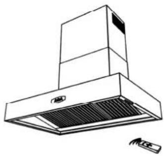
Line drawing of a multi-level industrial air duct hood with ventilation grilles and a label 'AGA' (no text or symbols beyond labeling)AGA
Station Road, Ketley,
Telford, Shropshire, TF1 5AQ, England.
Tel: +44 (0) 8458 152020
Fax: +44 (0) 1952 222048
E-mail: warrantyteam@aga-web.co.uk
www.agaliving.com
ENGLISH
SECTION 1. INTRODUCTION
Your range cooker is a semi-professional unit which gives you the power and flexibility to realise your full potential in the kitchen. Inevitably, during the cooking process, there will be heat, vapours and fumes produced. Your Aga extractor has been designed to complement the range cooker both in looks and performance in order to create the ideal environment for creative cooking.
SECTION 2. EXTRACTION PERFORMANCE
The most important influence on the performance of the extractor is the design of the ducting which takes the exhaust air from the extractor to the outside wall louvre. The duct route should be a prime consideration during the initial stages of the kitchen design. Please note the following:
- The extractor is provided with a spigot suitable for connecting 150mm diameter duct.
- Note: 150mm is the minimum duct diameter consistent with efficient extraction.
- The exhaust duct route length should be kept as short as possible (≤ 5m) with as few bends as possible.
- The most efficient configuration is to duct straight through an outside wall so try to position the cooker against an outside wall when designing your kitchen layout.
- The hood can be vented either to the top exhaust or the rear exhaust position. Use the position which gives the shortest duct route length and least number of bends. (The blower will need to be rotated for ducting directly through the rear exhaust position.)
- A route with more than two 90° bends will significantly degrade the performance of the extraction system. If possible, avoid having a 90° bend at the extractor exhaust spigot; keep bend radii as large as possible to maintain a smooth airflow without vortices; avoid kinks in flexible ducting; pull flexible ducting taut over straight runs to ensure that the internal surface is as smooth as possible.
SECTION 3. IMPORTANT INFORMATION
The following minimum headroom is required to accommodate the cooker and hood:
| Cooker-to-hood clearance (min) | 800 mm |
| Hood height including chimney | 680 – 825 mm |
| Minimum ceiling height with standard chimney | 2400 mm |
For a small charge customised replacement chimneys can be produced to suit your requirements.
The minimum distance between the range hob burners and the bottom of the extractor is essential to prevent overheating of the extractor and its components.
Please also note that a 90^ bend in the flexible ducting will require 215mm minimum headroom to give a smooth radius with no kinking.
Requirements of the relevant authorities concerning the discharge of exhaust air must be complied with.
Attention:
This appliance requires an earth connection.
Ensure that the supply voltage corresponds to that marked on the rating label inside the extractor.
The extractor must be isolated from the electrical supply before carrying out any cleaning or maintenance operations.
Pay particular attention to fire risk when frying. To minimise the risk of fire, all instructions relating to cleaning the grease filters and removing grease deposits must be adhered to.
Do not flambé under the extractor.
Warning
Proper care must be taken to ensure that the negative pressures caused by high performance extraction systems do not adversely affect the safe operation of certain types of fuel-burning appliances (gas, oil or solid fuel), including those installed in the kitchen and possibly also those installed in other parts of the house.
Where such fuel-burning appliances are installed, adequate ventilation MUST be provided in the room of installation, located and sized such that the negative pressure in the room created by the extractor does not exceed 4Pa.
In case of doubt, do not operate the extractor and fuel-burning appliance(s) simultaneously and consult an appropriate (for the fuel type) expert for advice.
The exhaust air must not be discharged into a flue which is used for exhausting fumes from appliances supplied with energy other than electricity, e.g. oil or gas-fired central heating boilers, gasfired water heaters, etc.
Adequate ventilation of the room must be provided when the cooker, extractor and appliances supplied with energy other than electricity (e.g. gas-fired or oil-fired heaters, etc.) are used simultaneously. The room must be provided with vents to allow a constant flow of fresh air.
SECTION 4. INSTALLATION
Refer to the drawings for your model (Page 17-18)
4.1 Removing the Grease Filters
Place extractor on its backplate on a horizontal surface.
To remove the grease filters, pull/lift the filter release lever away from the hood base. This releases the retaining clips allowing the filter to be carefully lifted away from the hood. Take care not to scratch the hood.
The internal fixing holes, blower assembly and spigot blanking plate can now be accessed through the openings in the baseplate.
4.2 Blower Exhaust Position
The hood can be vented either to the top exhaust or the rear exhaust position. Each exhaust position has 4 fixings onto which can be secured either the blower assembly or a blanking plate.
Bolt blower assembly to chosen exhaust position and the blanking plate to the unused position.
When changing the exhaust position, care should be taken not to excessively pull or twist the cable attached to the blower.
4.3 Duct Installation
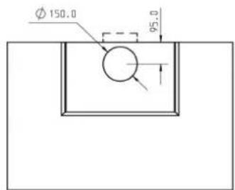
Make a hole in the wall or ceiling to take 150mm diameter ducting from the extractor exhaust spigot to the outside.
The exhaust duct route length should be kept as short as possible with as few bends as possible (Section 2).
Make a hole in the outside wall to suit the duct and external weather louvre.
4.4 Fixing the Hood to the Wall
If you are fitting a Splashback it must be fitted before the hood.
Note: The decorative chimney can be removed to ease handling of the hood.
The supporting wall must be of good quality, have an even surface and be sturdy enough to support the extractor.
Fixings must be used which are suitable for the type of wall construction.
Method:
- Mark a horizontal line to denote the bottom edge of the hood - if you have already fitted a splashback then the top edge of this will serve.
- Mark a vertical centre line of the range cooker and the hood.
- Remove the grease filters to gain access the internal fixing holes.
- Mark the positions of the fixing hole centres, as shown in the drawings for your model.
Tip: Offer the hood up to the wall in the desired position and mark the wall through the fixing holes in the hood rear. This is a 2-person job.
- Mark and prepare a hole suitable to accommodate 150mm diameter ducting (160mm min). If using the rear exhaust spigot position then accuracy is critical.
- Secure hood and chimney bracket, using fixings suitable for the wall construction, in the previously marked positions.
4.5 Connecting the Ducting
Connect ducting to extractor exhaust spigot. This may have to be done prior to fixing the extractor to the wall. You may find this easier with the chimney removed. The chimney is attached using M4 machine screws which can be accessed through the filter opening(s).
When the extractor is in position, check that the duct has not been flattened or kinked along its route.
Connect the ducting to the wall louvre spigot or alternative outside termination.
Secure the louvre to the outside wall. Ensure that any air fins are directed downwards.
Refit the grease filters.
4.6 Electrical Installation
The extractor is a stationary appliance designed to be connected by fixed wiring to the electrical supply.
ELECTRICAL HAZARD DISCONNECT ELECTRICAL SUPPLY BEFORE PROCEEDING FURTHER
A competent electrical technician must perform the electrical installation.
The extractor must be fed from a 230Vac single phase electrical supply using a switched spur fitted with a 3A fuse. The spur should be located adjacent to the extractor/cooker so that the supply can be disconnected from the extractor using the switch. The means of disconnecting from the supply must have a minimum contact separation of 3mm in all poles. Alternatively, a means of disconnection in the fixed wiring according to the relevant wiring rules must be fitted.
A supply cord for connecting the spur to the extractor is included.
The mains supply is connected to the free end of this cord as follows:
| INCOMING SUPPLY CABLE CONNECTIONS | |
| Live | Brown |
| Neutral | Blue |
| Protective Earth | Green/Yellow |
SECTION 5. OPERATING INSTRUCTIONS
Switch power on at the fused spur.
Pushbutton Functions

Motor RUN ON TIMER (OFF after 10 minutes to clear fumes)

Motor ON -INTENSIVE MODE (Reverts to speed 3 after 5 mins)

Motor ON - SPEED 3 (Maximum Speed for Normal Use)

Motor ON - SPEED 2

Motor ON - SPEED 1 Motor OFF

Lights ON/OFF
Remote Control Functions
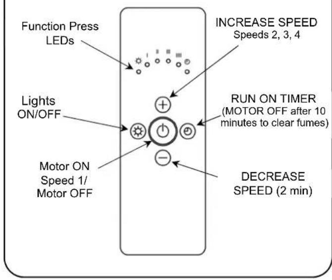
The extractor controller will automatically switch off the appliance if there has been no operator action for 4 hours.
After 30 hours accumulated running, GREASE FILTER CLEANING will be signalled by all 6 indicators flashing. Reset by pressing RUN ON TIMER Pushbutton.
SECTION 6. MAINTENANCE
Regular maintenance is essential to ensure good performance and long-life.
To maintain the immaculate appearance of the extractor, and to minimise fire risk, ensure that grease deposits on the extractor surfaces are kept to a minimum by regular cleaning.
To clean the stainless steel surfaces of the extractor, use a soft cloth and a suitable cleaning agent, such as a specially produced stainless steel cleaner or washing up detergent and warm water.
Painted surfaces should be cleaned using a soft cloth, detergent and warm water.
- Do not use abrasive cleaning materials or products on any hood surfaces.
- Do not use bleach-based cleaning products on any hood surfaces.
Clean the grease filters in a dishwasher or by hand-washing in hot water and detergent. Wash the filters at least every 2 months - sooner if the extractor is used extensively and filters become grease laden.
Whilst you can expect years of service from your grease filters, they are considered a consumable item and may deteriorate over time and need replacement, particularly when cleaned in a dishwasher.
For all users, filters should be replaced whenever they exhibit signs of physical wear.
To remove the grease filters, pull the filter release lever away from the hood base, releasing the sprung latch, allowing the filter to be lifted away from the hood. Care should be taken not to scratch the hood.
LED lamps require no end user maintenance.
SECTION 7. SPECIFICATIONS
| Blower airflow, nominal: 800 m3/hr | |
| Supply voltage: 230V~50Hz | |
| LED lamp voltage: 12V | |
| Blower power input: 1 @ 275W | |
| Lamp power: 3 x 2.6W | |
| Fuse size for electrical supply: 3A | |
| Blower spigot diameter: 150mm | |
| Approximate Hood Weights:SH890 31KgSH990 34KgSH1090 37Kg |
For detailed specification and energy efficiency information please refer to the product fiche for your hood.
FRANÇAIS
SECTION 1. INTRODUCTION
4.5 Connecting the Ducting
4.6 Electrical Installation
Pushbutton Functions

Place extractor on its backplate on a horizontal surface.
4.2 Uitlaatpositie
4.6 Electrical Installation
Pushbutton Functions

| INCOMING SUPPLY CABLE CONNECTIONS | |
| Live | Brown |
| Neutral | Blue |
| Protective Earth | Green/Yellow |
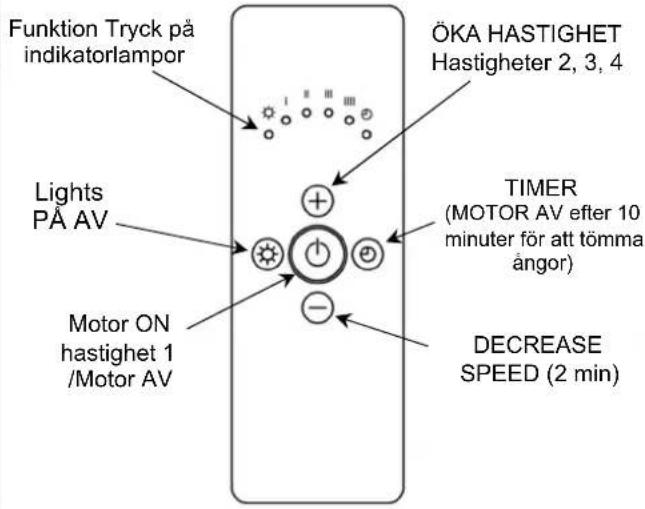
AVSNITT 5. ANVÄNDNINGSANVISNINGAR
Pushbutton Functions

Remote Control Functions
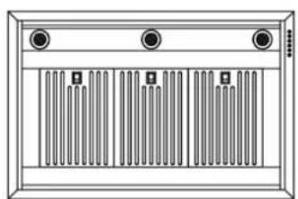
Rear View Showing Fixing Positions

Side View
natural_image
Front view of a rectangular electronic device with three ports and vertical striped panels (no text or symbols visible)Base View
Plan View
natural_image
Line drawing of a stainless steel kitchen range hood with ventilation grille and control panel (no text or symbols)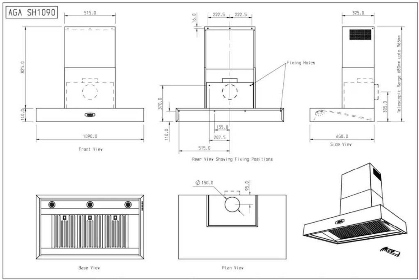

- AGA
- ENGLISH
- SECTION 1. INTRODUCTION
- SECTION 2. EXTRACTION PERFORMANCE
- SECTION 3. IMPORTANT INFORMATION
- Attention:
- Warning
- SECTION 4. INSTALLATION
- Refer to the drawings for your model (Page 17-18)
- Removing the Grease Filters
- Blower Exhaust Position
- Duct Installation
- Fixing the Hood to the Wall
- Method:
- Connecting the Ducting
- Electrical Installation
- SECTION 5. OPERATING INSTRUCTIONS
- Pushbutton Functions
- SECTION 6. MAINTENANCE
- FRANÇAIS
- Uitlaatpositie
- AVSNITT 5. ANVÄNDNINGSANVISNINGAR
- Remote Control Functions
Brand : AGA
Model : SH890
Category : Range hood