
WMTS30A10C - Generator WESTINGHOUSE - Free user manual and instructions
Find the device manual for free WMTS30A10C WESTINGHOUSE in PDF.

| Product Type | Manual Transfer Switch |
| Brand | Westinghouse |
| Model | WMTS30A10C |
| Number of Circuits | 8 (6 circuits 120 V 15 A + 2 circuits 120/240 V 20 A) |
| Generator Input Voltage | 240 V AC (floating neutral) |
| Integrated Circuit Breakers | 6 single-pole 15 A, 2 single-pole 20 A |
| Power Inlet Box | NEMA 3R, UV-resistant ABS material, L14-30P receptacle |
| Housing Material | Steel for switch, ABS for inlet |
| Dimensions (switch) | Approximately 30.5 x 20.3 x 10.2 cm (12 x 8 x 4 in) |
| Weight (approximate) | 4.5 kg (10 lb) |
| Usage | Indoor, mounted within 40 cm of distribution panel |
| Installation | By a qualified electrician, in accordance with local codes |
| Safety | Automatic disconnection of utility power in GEN position, overload protection |
| Maximum Load Capacity | 30 A per phase (depending on generator) |
| Warranty | 5 years (limited, parts and labor) |
| Included Accessories | Inlet box, power cord, PVC fittings, manual |
| Maintenance | Annual connection check, no lubrication needed |
| Repairability | Spare parts available via customer service |
Frequently Asked Questions - WMTS30A10C WESTINGHOUSE
User questions about WMTS30A10C WESTINGHOUSE
0 question about this device. Answer the ones you know or ask your own.
Ask a new question about this device
Download the instructions for your Generator in PDF format for free! Find your manual WMTS30A10C - WESTINGHOUSE and take your electronic device back in hand. On this page are published all the documents necessary for the use of your device. WMTS30A10C by WESTINGHOUSE.
USER MANUAL WMTS30A10C WESTINGHOUSE
WMTS30A10C
MANUAL TRANSFER SWITCH
30-AMP/8-CIRCUITS
DO NOT RETURN THIS PRODUCT TO THE STORE
If you have questions or need assistance, please call customer service at 855-944-3571.
Introduction....2-3
Safety 4-6
Electrical....6
Components 7-8
Assembly 8-9
Installation 9-14
Operation....14-16
Troubleshooting....17
Warranty 18
Schematics....19
Service Hotline ....Back Page
INTRODUCTION
Installation and maintenance of this transfer switch must be performed by a qualified electrician in accordance with applicable electrical codes. Some jurisdictions may require the installation to be inspected by local authorities. Keep all relevant installation, inspection, and maintenance information.
WARNING This product can expose you to chemicals including Di-n-butyl phthalate (DBP) which is known to the State of California to cause Developmental Harm.
DISCLAIMERS
All information, illustrations, and specifications in this manual were in effect at the time of publishing. The illustrations used in this manual are intended as representative reference views only. We reserve the right to make any specification or design change without notice.
ALL RIGHTS RESERVED
All rights reserved. No reproduction allowed in any form without written permission from Westinghouse Outdoor Power Equipment.

⚠️DANGER Read this manual before using or performing maintenance on this product. Failure to follow the instructions and safety precautions in this manual can result in serious injury or death.
UPDATES
The latest User Manual for your Westinghouse products can be found under our support tab. wpowereq.com/pages/manuals
Or scan the following QR code with your smartphone camera to be directed to the link.

PRODUCT REGISTRATION
For trouble-free warranty coverage, it is important to register your Westinghouse product.
You can register by:
- Completing and mailing the product registration card included in the carton.
- Registering your product on-line at: wpowereq.com/pages/warranty-registration
- Scanning the above QR code with your smartphone camera to be directed to the mobile registration link.
For Your Records
Date of Purchase: ____
Model Number: ____
Serial Number: ____
Place of Purchase: ____
- Sending the following product information to:
Westinghouse Outdoor Power
Warranty registration
777 Manor Park Drive
Columbus, OH 43228
IMPORTANT: Keep your purchase receipt for trouble-free warranty coverage.

TRANSFER SWITCH
Prewired ....Yes
Enclosure.... Steel
Conduit Size 1-1/4 in. flexible
Circuit Breakers....8
Circuit Breakers (15A, single pole) 6
Circuit Breakers (20A, single pole) ......2
POWER INLET BOX
NEMA Rating....UL, CSA, cETL
Material.....ABS, UV Resistance for Outdoor, Flame Retardant (UL or CSA/cETL Certified)
Receptacle.....L14-30P
Knockout Holes ....3
NOTICE
Thank you for choosing Westinghouse!
PLEASE READ BEFORE RETURNING THIS PRODUCT FOR ANY REASON.
If you have a question or experience a problem with your Westinghouse purchase, call us at 1-855-944-3571 to speak with an agent.
SAVE THIS MANUAL FOR FUTURE REFERENCE.
HAVE QUESTIONS?
Email us at service@wpowereq.com
or call 1-855-944-3571
SAFETY DEFINITIONS
The words DANGER, WARNING, CAUTION, and NOTICE are used throughout this manual to highlight important information. Make sure that the meanings of this safety information is known to all who operate, perform maintenance on, or are near the generator.

This safety alert symbol appears with most safety statements. It means attention, become alert, your safety is involved! Please read and abide by the message that follows the safety alerts symbol.
⚠️ DANGER Indicates a hazardous situation which, if not avoided, will result in death or serious injury.
WARNING Indicates a hazardous situation which, if not avoided, could result in death or serious injury.
CAUTION Indicates a hazardous situation which, if not avoided, could result in minor or moderate injury.
NOTICE Indicates a situation which can cause damage to the generator, personal property, and/or the environment, or cause the equipment to operate improperly.
NOTE: Indicates a procedure, practice or condition that should be followed for the generator to function in the manner intended.
SAFETY SYMBOLS
Follow all safety information contained in this user's manual as well as the information on the product labeling.
| Symbol | Description |
 | Safety Alert Symbol |
 | Fire Hazard |
 | Electrical Shock Hazard |
 | Burn Hazard. Do not touch hot surfaces. |
 | Asphyxiation Hazard |
 | Do Not Operate in Wet Conditions |
 | Read Manufacturer's Instructions |
 | Maintain Safe Distance |
 | Ground. Consult with electrician to determine grounding requirements before operation. |
 | Carbon Monoxide |
IMPORTANT SAFETY INSTRUCTIONS
- The National Electrical Code requires the use of a transfer switch or other suitable transfer equipment whenever a portable generator is connected to a building's electrical system. Transfer switches isolate generator power from utility power and prevent backfeeding of electric power into the utility system.
DANGER
Fire and electrocution hazard.
DO NOT connect to a building's electrical system unless the generator and a transfer switch have been properly installed and the electrical output has been verified by a qualified electrician. The connection must isolate the generator power from utility power and must comply with all applicable laws and electrical codes. Failure to properly isolate the generator power could cause property damage and create a dangerous backfeed of electricity which could kill or seriously injure utility workers.
WARNING
Use approved transfer
switches and equipment to isolate generator power from utility power. Using non-approved transfer switches can result in death, serious injury, and equipment damage.
- Installation and maintenance of this transfer switch must be performed by a qualified electrician in accordance with applicable electrical codes. Some jurisdictions may require the installation to be inspected by local authorities. Keep all relevant installation, inspection, and maintenance information.
WARNING
Using transfer switches that
are improperly installed and maintained could result in electrocution or fire, which can cause death or serious injury.
DANGER
Do not wire or operate the
transfer switch or any electrical equipment while barefoot, with wet hands or feet, while standing in water or in wet conditions. Doing so will create a dangerous electrical shock hazard that will result in death.
DANGER
Handle transfer switches
with care during installation. Never mount or wire a damaged transfer switch. A damaged transfer switch could malfunction and create electrical hazards that could result in death, serious injury, and equipment failure.
WARNING
Only licensed and qualified
professional should wire and install transfer switches. Improper installation can result in death, serious injury, and equipment or property damage.
- Always ensure that the main circuit breaker in the load center is in the OFF position before installing the transfer switch, changing the electrical source, or performing maintenance.
DANGER
Risk of Electrocution. Turn the
main circuit breaker in the load center OFF before connecting circuits to the transfer switch. Contact with live terminals will result in severe electric shock, personal injury, and death.
DANGER
In case of an electrical
emergency, immediately shut the power OFF. If necessary, separate the victim from live conductors using non-conductive items like a PVC pipe or wooden broomstick. If the victim is unconscious administer first aid and get medical assistance immediately. Failure to act promptly will result in death or serious injury.
SAFETY INSTRUCTIONS FOR USING PORTABLE GENERATORS
- Portable generators should only be used outside and far away from vents, windows, and doors.
NOTICE
Install battery-powered carbon
monoxide detectors or plug-in carbon monoxide detectors with battery back-up in living areas.
DANGER
Using a generator indoors CAN KILL YOU IN MINUTES. Generator exhaust contains carbon monoxide. This is a poison you cannot see or smell.

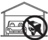
NEVER use inside a home or garage, EVEN IF doors and windows are open.


Only use OUTSIDE and far away from windows, doors, and vents.
- This transfer switch should only be connected to a generator with neutral floating.
● Always turn the generator off before connecting or disconnecting the power cord. - Monitor the wattage meters and balance electrical loads to avoid tripping the generator's circuit breakers or hindering the generator's performance.
NOTICE
Do not connect branch circuits
with appliances or systems that exceed the switch or the generator's load capacity. Exceeding the load capacity could damage the switch, the generator, and any connected devices.
ELECTRICAL
CHOOSING LOAD AND TRANSFER CIRCUITS
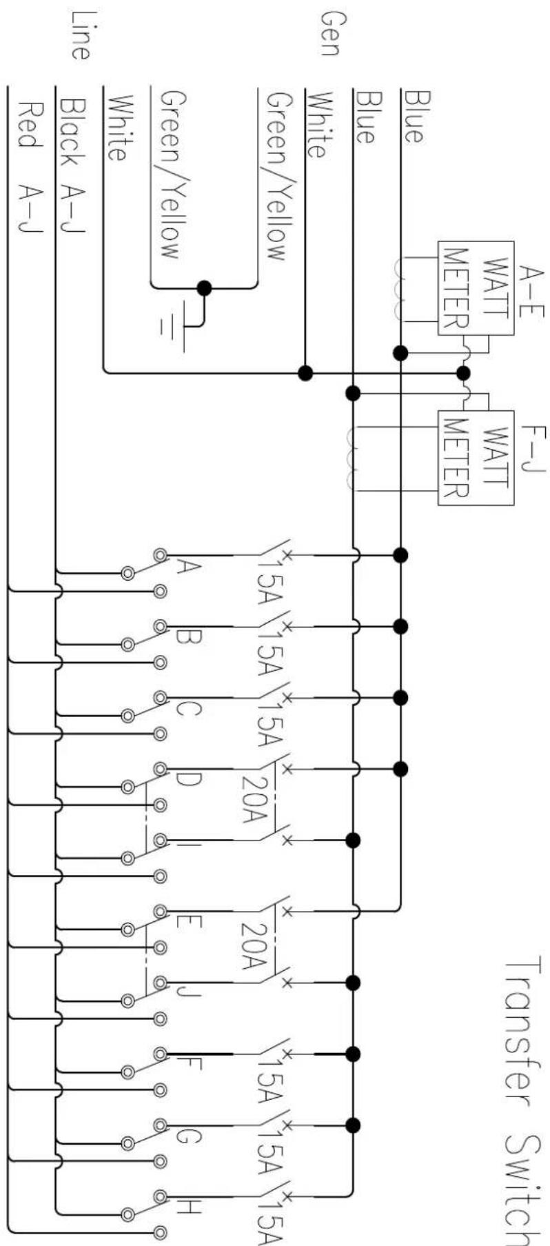
- With the help of a qualified electrician, decide which branch circuits inside the load center will use generator power when the switch is operational. Choose up to six circuits that include 120V appliances and equipment and up to two circuits that include 240V appliances and equipment.
NOTE: If you are unsure about the voltage requirement for a device connected to a branch circuit, remove that device before connecting the branch circuit to the transfer switch.
- After identifying the branch circuits, select corresponding transfer circuits based on amperage and wattage. Branch circuits with 15A breakers can be paired to one of six transfer circuits with 15A breakers. Branch circuits with 20A breakers can be paired to one of two transfer circuits with 20A breakers. Try to distribute loads with similar wattage requirements equally on either side of the switch. Refer to Wattage Capacity later in this section.
NOTE: Do not pair circuits if the amperage rating for branch circuit exceeds the rating for the transfer circuit.
WATTAGE CAPACITY
Be certain that the generator can produce enough start-up and running wattage to power all of the items connected to the circuits you select. Wattage information for most devices can be found directly on the unit.
NOTICE
Do not overload the generator's
capacity. Exceeding the generator's wattage/amperage capacity can damage the generator and/or electrical devices connected to it.
Starting watts are typically higher than running watts since some electrical motors draw more power when first started. Use the watt meters on the transfer switch to monitor start-up surges and ensure the generator is not overloaded.
For optimal performance the loads on the left side of the transfer switch (circuits A-E) should be balanced with the loads on the right side (circuits F-J) to within a 1000W. If necessary turn off the generator, ensure that the main circuit breaker in the load center is in the OFF position, and rebalance the load.
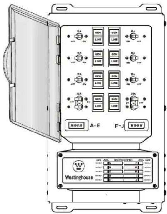
FIG. 1
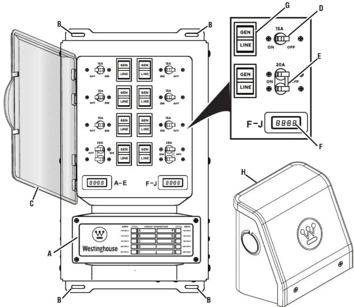
A - Circuit Description Chart
B - Mounting Holes
C - Cover
D - 15 Amp Circuit Breaker
E - 20 Amp Circuit Breaker
F - Wattage Meter
G - Circuit Selector
H - Power Inlet Box
UNDERSTANDING YOUR TOOL
See Figure 1.
To reduce the risk of injury and product failure, read and understand the information in this user's manual as well as the information on the product labeling.
CIRCUIT BREAKERS
The 15A and 20A circuit breakers on the transfer switch provide protection to the branch circuit when the circuit selector is in the "GEN" position.
NOTE: When the circuit selector is in the "LINE" position, the branch circuits are protected by the circuit breakers in the load center.
CIRCUIT SELECTORS
The three position circuit selectors allow you to select or remove power sources for the branch circuits wired through the transfer switch. To connect branch circuits to a generator select "GEN", to connect circuits to the load center (utility) select "LINE", and to disconnect circuits from all power sources select "OFF" (center).
CAUTION
If a branch circuit is connected to the transfer switch and a GFCI or AFCI breaker at the load center, the branch circuit will only get GFCI or ACFI protection when the circuit selector is in the "LINE" position. GFCI and AFCI protection is not provided when the circuit is powered by a generator. GFCI or AFCI protection provided at the outlet(s) will still be functional.
POWER INLET BOX
The power inlet box is mounted outdoors to provide a safe means of connecting a generator to the transfer switch.
A DANGER Asphyxiation hazard. When operating a generator, make sure it is located in an open, outdoor area, at least 20 ft. (6 m.) from occupied spaces with exhaust pointed away.
ASSEMBLY
REMOVING CARTON CONTENTS
WARNING This product does not require assembly. Do not attempt to operate this product if it is not completely assembled. Using an improperly assembled product can be hazardous and could result in serious personal injury.
- Remove and inspect the carton contents. Verify that all the items in the INCLUDED LIST are present and undamaged.
● Recycle or dispose of the packaging materials properly.
INCLUDED LIST
See Figure 2.
Transfer Switch, Power Inlet Box, Power Cord, 1 in. PVC Fitting, 1-1/4 in. PVC Fitting, Conduit, and User Manual
If any parts are missing, contact our service team at service@wpowereq.com or call 1-855-944-3571.
WARNING Do not alter or modify this product unless instructed to do so in this manual or by the manufacturer. Do not use attachments or accessories that are not recommended for use with this product. Making unauthorized modifications and using incompatible accessories can damage the unit and void your warranty.
NOTICE An electrical junction box is needed, but not included, to install and operate the transfer switch.
WATTAGE METER
The meters indicate the total load on either side of the switch for branch circuits powered by a generator. The meters do not measure load amounts for circuits powered by the load center (utility).
NOTE: The meter on the left is for circuits A-E and the meter on the right is for circuits F-J
FIG. 2
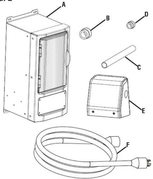
A - Transfer Switch
B - 1-1/4 in. PVC Fitting
C - Conduit
D - 1 in. PVC Fitting
E - Power Inlet Box
F - Power Cord
OVERVIEW
See Figure 3.
The transfer switch allows you to safely use generator power through existing electrical wiring. Once the transfer switch is installed, you can use the circuit selectors to determine the power source for each circuit connected to the switch. The switch will not allow you to use generator and utility power at the same time.
CAUTION Generator output voltage must be 240VAC. This switch is not compatible with 120VAC generator output voltage.
DANGER Asphyxiation hazard. When operating a generator, make sure it is located in an open, outdoor area, at least 20 ft. (6 m.) from occupied spaces with exhaust pointed away.
FIG. 3
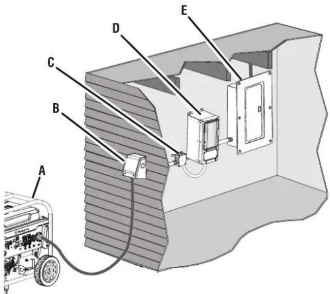
A - Generator
B - Power Inlet Box
C - Junction Box
D - Transfer Switch
E - Load Center (Utility)
INSTALLATION
MOUNTING THE TRANSFER SWITCH
See Figures 4 - 9.
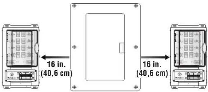
Always mount the transfer switch indoors and no farther than 16 inches away from the load center. When choosing a suitable location consider the layout of the room, user convenience, and the proximity to the load center.
DANGER Handle transfer switches with care during installation. Never mount or wire a damaged transfer switch. A damaged transfer switch could malfunction and create electrical hazards that could result in death, serious injury, and equipment failure.
- Turn the main circuit breaker in the load center to the OFF position.
NOTE: Power should remain off during installation. Take all appropriate actions for prolonged power outages including actions that will preserve food and protect sensitive equipment.
DANGER Turning the main circuit breaker in the load center to the OFF position, does not shut off power on the utility side of the main breaker. The wires on the utility side are still live and contact with them can result in serious injury and death.
- Select a suitable location for the transfer switch approximately 16 in. away from the load center. Mark the location.
FIG. 4
- Locate the two nearest studs on either side of the mark.
● Install two 2x4s approximately 19 in. apart between each stud as shown in figure 5. - Hold the transfer switch against the 2x4s and mark hole locations.
- Mount the switch to the 2x4s using appropriate fasteners.
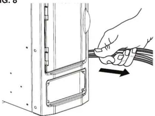
- Unthread the screws securing the front panel and remove the panel to reveal the two wire bundles inside.
NOTE: There are two wire bundles inside the transfer switch, a large bundle to connect the switch to the load center and a small bundle to connect the switch to a junction box or the power inlet.
- Remove the screws and knock outs on the left or right side depending on the location to the load center
- Remove the cover on the load center.
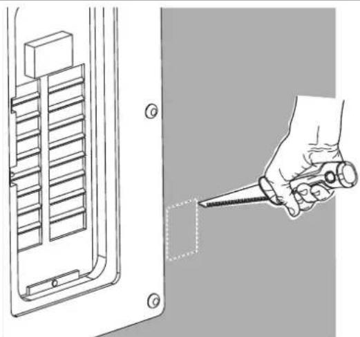
- Locate and remove the load center knock out closest to the transfer switch.
NOTE: If the load center is flush mounted, you may have to cut a hole in the drywall to access the knock out.
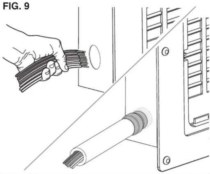
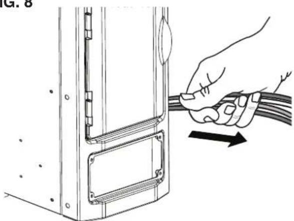
- Pull the large bundle of wires through the opening in the transfer switch closest to the load center and push it through the opening in the load center.
NOTE: If possible, protect the wire bundle by first attaching the conduit to the switch and load center using the fittings. Then insert the wire through the conduit.
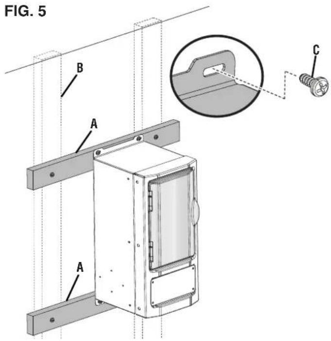
A - 2x4
B - Stud
C - Screw
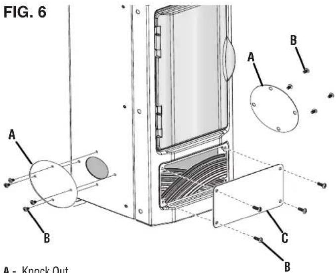
A - Knock Out
B - Screw
C - Front Panel
FIG. 7
natural_image
Technical illustration of a hand holding a screwdriver inserted into a component, with no visible text or symbols.FIG. 8
natural_image
Illustration of a hand holding a cable with an arrow indicating direction (no text or symbols present)A - Wire Bundle
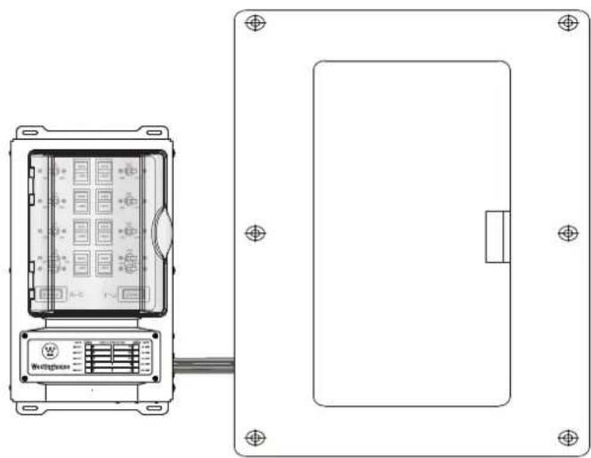
INSTALL ELECTRICAL JUNCTION BOX (NOT INCLUDED)
See Figure 10.
- Ensure that the main circuit breaker in the load center is in the OFF position.
- Mount the junction box within six inches of the transfer switch on the side farthest from the load center.
- Pull the small bundle of wires through the opening in the transfer switch closest to the junction box and connect it to the junction box.
NOTE: Use appropriate conduits and fittings to secure the wire bundle.
WARNING
After installation, ensure the front bottom cover and all other openings are properly reinstalled, covered, or sealed to prevent electrical components from being exposed.
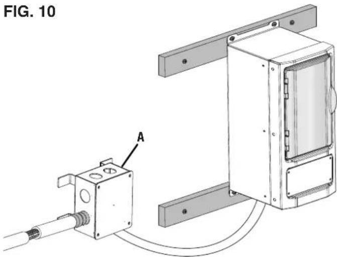
A - Junction Box (Not Included)
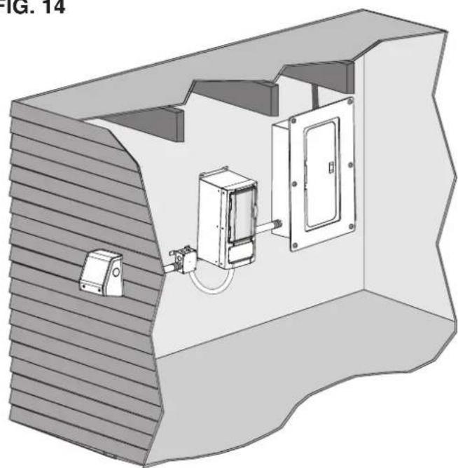
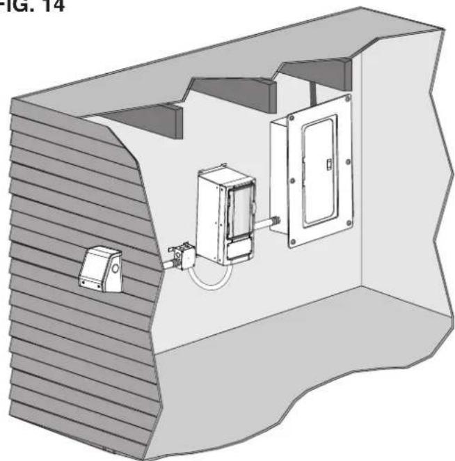
MOUNTING THE POWER INLET BOX
See Figures 11 - 14.
Mount the power inlet box outdoors at least 5 feet away from doors, windows, air conditioning units, and vents so portable generators can be connected and operated safely.
- Ensure that the main circuit breaker in the load center is in the OFF position.
- Select a suitable location for the power inlet box along an outside wall.
- Remove the screws in the front of the power inlet box.
- Separate the front cover, receptacle, and back cover.
- Place the back cover against the outside wall and mark hole locations including the center hole.
- Predrill three holes for the screws and use a hole saw to create an opening in the center hole position.
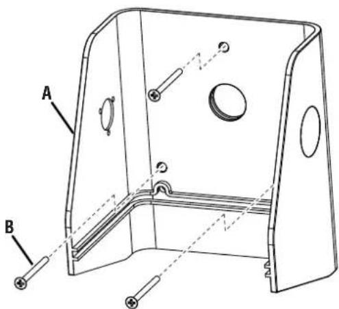
FIG. 11
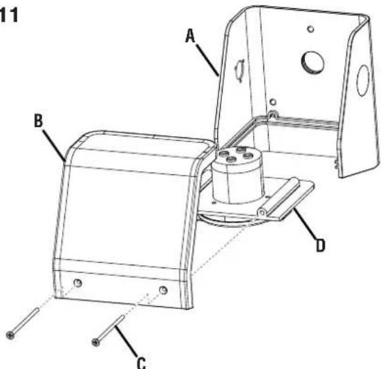
A - Back Cover
B - Front Cover
C - Screw
D - Receptacle
FIG. 12
A - Back Cover
B - Screw
NOTE: Use fittings listed for use in wet conditions and ensure the opening is above the level of uninsulated live parts in order to maintain the NEMA 3R rating.
- Mount the back cover to the wall using the appropriate hardware.
- Install four conductor (Hot/Blue, Hot/Blue, Neutral/White, Ground/Green-Yellow) permanent wiring into the junction box.
- Route the wiring through the opening in the exterior wall and the back cover.
- Connect the wiring to the receptacle.
- Slide the receptacle into the back cover.
- Secure the front cover to the back cover using screws.
FIG. 13

natural_image
Technical line drawing of a mechanical assembly with labeled component A (no text or symbols beyond label)A - Receptacle
FIG. 14

natural_image
3D technical illustration of a mechanical or electrical enclosure with internal components and wiring (no text or symbols)WIRING THE TRANSFER SWITCH TO THE LOAD CENTER
See Figures 15 - 20.
DANGER
In case of an electrical
emergency, immediately shut the power OFF. If necessary, separate the victim from live conductors using non-conductive items like a PVC pipe or wooden broomstick. If the victim is unconscious administer first aid and get medical assistance immediately. Failure to act promptly will result in death or serious injury.
DANGER
Risk of Electrocution. Turn the
main circuit breaker in the load center OFF before connecting circuits to the transfer switch. Contact with live terminals will result in severe electric shock, personal injury, and death.
DANGER
Turning the main circuit
breaker in the load center to the OFF position, does not shut off power on the utility side of the main breaker. The wires on the utility side are still live and contact with them can result in serious injury and death.
WARNING
Only licensed and qualified
professional should wire and install transfer switches. Improper installation can result in death, serious injury, and equipment or property damage.
FIG. 15
natural_image
Technical line drawing of a device panel with internal components and wiring (no text or symbols)- Turn the main circuit breaker in the load center to the OFF position.
- Open the cover on the transfer switch.
- Remove the cover on the load center.
- Determine which branch circuits and transfer circuits will be connected. Consider voltage, amperage, and wattage capacity. Refer to the Electrical section earlier in this manual.
NOTE: Do not pair circuits if the amperage rating for branch circuit exceeds the rating for the transfer circuit.
- Fill out the circuit description chart located at the bottom of your transfer switch so you can identify circuits quickly.
To wire 120V circuits to the transfer switch:
- Locate the circuit breaker that you want to connect to the transfer switch.
- Loosen the lug on the circuit breaker and remove the existing the hot wire.
- Trim and strip the wires for the transfer circuit you want to connect.
NOTE: Each transfer wire is labeled to match the corresponding circuit. For instance, the transfer wires for transfer circuit "A" are labeled "A".
- Neatly route the transfer wires inside the load center's wiring compartment until they are close to the circuit breaker.
- Insert the red transfer wire into the circuit breaker and secure in place by tightening the lug.
- Twist the ends of the black transfer wire and the hot wire together.
- Secure the twisted end inside a wire cap and place the wires inside the load center's wiring compartment.
- Repeat this process to wire additional 120V circuits to the transfer switch.
To wire 240V circuits to the transfer switch:
- Locate the circuit breaker that you want to connect to the transfer switch.
- Loosen the lugs on the circuit breaker and remove the existing the hot wires.
- Trim and strip the wires for the transfer circuit you want to connect.
NOTE: There are two 240V transfer circuits, "D/I" and "E/J". The transfer wires for circuit "D/I" are labeled "D" and "I". The transfer wires for circuit "E/J" are labeled "E" and "J".
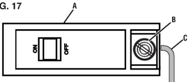
FIG. 16
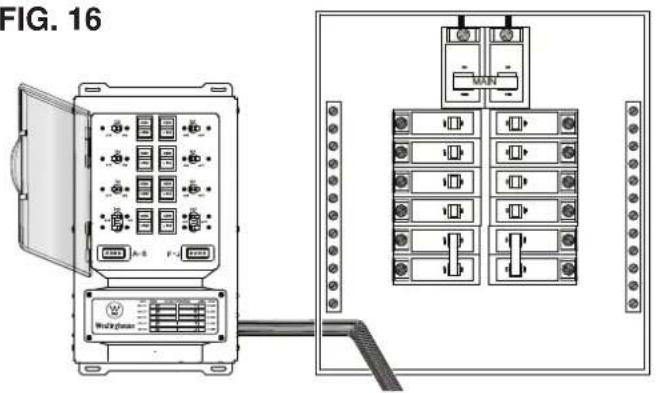
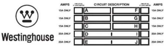
FIG. 17

A - 120V Circuit Breaker
B - Lug
C - Hot Wire
FIG. 18
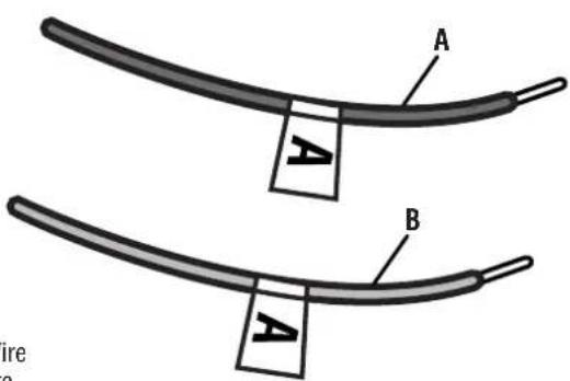
A - Black Wire
B - Red Wire
FIG. 19
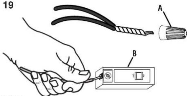
A - Wire Cap
B - 120V Circuit Breaker
- Neatly route the transfer wires inside the load center's wiring compartment until they are close to the circuit breaker.
- Insert the red transfer wires into the circuit breaker and secure in place by tightening the lugs.
- Twist the ends of one black transfer wire and one hot wire together. Repeat with second black transfer wire and hot wire.
- Secure the twisted ends inside wire caps and place the wires inside the load center's wiring compartment.
- Repeat this process to wire the remaining 240V circuit.
To complete installation:
- Trim and strip the white (neutral) transfer wire and the green (ground) transfer wire.
- Insert the white (neutral) transfer wire into any unused hole in the neutral bar and secure in place.
- Insert the green (ground) transfer wire into any unused hole in the ground bar and secure in place.
NOTE: If the load center does not have a separate ground bar, connect the green (ground) transfer wire into an unused hole on the neutral bar.
- Replace the load center cover.
- Place all the circuit selectors in the transfer switch in the "LINE" position.
- Place all the circuit breakers inside the load center, including the main circuit breaker, in the ON position.
FIG. 20
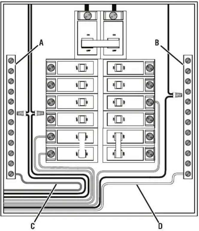
A - Ground Bar
B - Neutral Bar
C - Ground Wire
D - Neutral Wire
OPERATION
OPERATING/TESTING THE TRANSFER SWITCH
See Figures 21 - 24.
When powering branch circuits using utility power, the circuit selectors inside the transfer switch should be in the "LINE" position. Place the circuit selectors in the "GEN" position to operate branch circuits using generator power. To remove all power sources, place the selectors in the "OFF" position (center).
NOTE: You do not have to turn off any of the circuit breakers in the load center, including the main breaker, to operate the transfer switch.
To test/operate the transfer switch in the "LINE" position:
● Make sure that the circuit breakers in the load center, including the main breaker, are in the ON position.
- Place one or all of the transfer switch's circuit selectors in the "LINE" position.
- Verify that the branch circuits are receiving utility power and functioning normally.
- If a problem occurs, turn power off at the load center's main breaker and contact a qualified electrician.
FIG. 21
To test/operate the transfer switch in the "GEN" position:
- Make sure that the circuit breakers in the load center, including the main breaker, are in the on position.
- Place a portable generator outside near the power inlet box.
! DANGER
Asphyxiation hazard. When
operating a generator, make sure it is located in an open, outdoor area, at least 20 ft. (6 m.) from occupied spaces with exhaust pointed away.
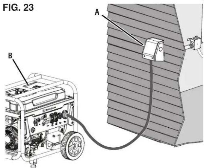
- Insert the male end of the power cord into the generator's receptacle and twist to lock.
NOTE: To remove, twist the cord counterclockwise and remove it from the generator.
- Insert the female end of the power cord into the power inlet box's receptacle and twist to lock.
NOTE: To remove, twist the cord counterclockwise and remove it from the power inlet box.
- Check the generator's fuel and lubricant levels.
- Start the generator according to the generator manufacturer's instructions. Allow the generator to warm up for approximately 10 minutes.
- Place one of the transfer switch's circuit selectors in the "GEN" position and monitor the load in the wattage meter.
- Continue monitoring the wattage usage while turning another circuit selector to the "GEN" position. Repeat this process until all desired circuit selectors are in the "GEN" position. Do not overload your generator.
NOTE: You do not have to engage circuit selectors in a particular order, but the selectors should be engaged one at a time and in such a way that the loads on both sides of the switch remain balanced within 1000W of each other.
NOTICE
Do not connect branch circuits
with appliances or systems that exceed the switch or the generator's load capacity. Exceeding the load capacity could damage the switch, the generator and any connected devices.
- Verify that the branch circuits are receiving generator power and functioning normally.
- If a problem occurs, turn off the generator and turn power off at the load center's main breaker. Contact a qualified electrician.
FIG. 22
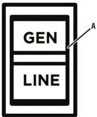
A - Circuit Selector
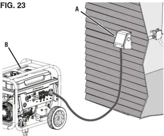
A - Generator
B - Power Inlet Box
FIG. 24
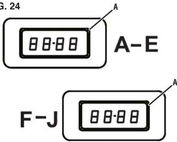
A - Wattage Meter
To test/operate the transfer switch in the "OFF" position (center):
- Make sure that the circuit breakers in the load center, including the main breaker, are in the on position.
- Place one or all of the transfer switch's circuit selectors in the "OFF" position (center).
- Verify that the branch circuits are not receiving utility or generator power.
- If a problem occurs, turn power off at the load center's main breaker and contact a qualified electrician.
RESETTING THE TRANSFER SWITCH'S CIRCUIT BREAKERS
See Figure 25.
If a generator has enough wattage capacity, all of the transfer circuits can be used simultaneously. If an electrical load exceeds the transfer switch's load capacity, the circuit breakers inside the switch may trip
To reset a circuit breaker:
- Remove the overload condition.
- Move the circuit selector beside the tripped breaker into the "OFF" position (center).
-
Move the tripped breaker into the full off position then to the fully on position.
-
Move the circuit selector beside the breaker back to the "GEN" position and resume operation.
- If a problem occurs, turn power off at the load center's main breaker and contact a qualified electrician.
FIG. 25
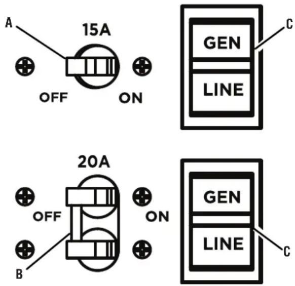
A - 15 Amp Circuit Breaker
B - 20 Amp Circuit Breaker
C - Circuit Selector
| PROBLEM POSSIBLE | CAUSE CORRECTION | |
| Generator is running but there is no electrical output | Generator circuit breaker has tripped. Reset circuit breaker. Refer to generator's user manual. | |
| Power cord connected incorrectly or power cord is defective. | Reconnect power cord. If the problem repeats a second time, replace the power cord. If the problem repeats again, contact Westinghouse customer service toll-free at 1 (855) 944-3571. | |
| Faulty device or appliance. Connect a different device or appliance in good condition. | ||
| Damaged or defective generator. Shut off the generator. Contact the generator manufacturer. | ||
| Generator running rough or stalling when load applied | Faulty device or appliance. Connect a different device or appliance in good condition. | |
| Generator is overloaded. Review load power requirements and rearrange. | ||
| Equipment or appliances not running using generator power | The circuit selector is in the “OFF” or “LINE” position. | Move the circuit selector to the “GEN” position. |
| Generator circuit breaker has tripped. Reset circuit breaker. Refer to generator's user manual. | ||
| Power cord connected incorrectly or power cord is defective. | Reconnect power cord. If the problem repeats a second time, replace the power cord. If the problem repeats again, contact Westinghouse customer service toll-free at 1 (855) 944-3571. | |
| Faulty device or appliance. Connect a different device of appliance in good condition. | ||
| Damaged or defective generator. Shut off the generator. Contact the generator manufacturer. | ||
| Equipment or appliances not running using utility power | The circuit selector is in the “OFF” or “GEN” position. | Move the circuit selector to the “LINE” position. |
| The circuit breaker in the load center has tripped. | Reset the circuit breaker in the load center. | |
LIMITED WARRANTY STATEMENT
MWE INVESTMENTS, LLC 5 YEAR LIMITED WARRANTY
OWNER'S RESPONSIBILITY
Your receipt for purchase including the date, model and serial number must be maintained and presented to a service provider for warranty service. Proof of purchase rests solely with you, the original purchaser.
To help ensure trouble free warranty coverage, we recommend that you register your Westinghouse transfer switch. You may register on-line at www.WestinghouseOutdoorPower.com/register- your-product/, or by automated phone at 1-855-944-3571, or by filling out and returning to MWE Investments, LLC the registration card supplied with your transfer switch. Choosing to register your product allows you to place your proof of purchase on file with us for safekeeping in case of future coverage and provides a direct link between you and MWE Investments, LLC if we find it necessary to contact you.
You must demonstrate reasonable care and use as prescribed in the operator's manual for your Westinghouse transfer switch. Should a product difficulty occur, it is your sole responsibility, at your expense, to deliver or ship your Westinghouse transfer switch to a service provider for warranty repairs or replacements (which must occur within the applicable warranty period), and arrange for pick-up or return transportation charges of your transfer switch after the repairs have been made. You can also contact MWE Investments, LLC directly to request replacement parts under warranty. For assistance in locating a service provider near you, you may contact MWE Investments, LLC's automated phone at 1-855-944-3571 or you may locate a service provider at www.WestinghouseOutdoorPower.com. Should you require assistance, replacement parts under warranty, or have questions, email us at service@wpowereq.com or call 1-855-944-3571.
MWE INVESTMENTS, LLC'S RESPONSIBILITY
MWE Investments, LLC warrants to the original purchaser that its Westinghouse line of transfer switches will be free from defects in material and workmanship, including defects that result in electrical or mechanical breakdown. Under normal use and maintenance from the date of purchase, MWE Investments, LLC agrees to repair or replace at MWE Investments, LLC's discretion, any defective product free of charge at any service provider within five years from the date of purchase. THIS LIMITED WARRANTY IS EXTENDED TO THE ORIGINAL PURCHASER ONLY AND IS NOT TRANSFERABLE TO SUBSEQUENT OWNERS.
DO NOT RETURN THE UNIT TO THE PLACE OF PURCHASE
Contact customer service and our service team will troubleshoot any issue by phone or e-mail. If the problem persists, MWE Investments, LLC will, at its discretion, authorize assessment, replacement or repair of the defective part or component by an authorized party.
EXCLUSIONS
The following equipment and repairs are not covered under this warranty.
Normal Wear Items
Overtime, mechanical and electrical items inside this device will need to be repaired or replaced in order to maintain optimal performance. When a part or piece of equipment has reached the end of its useful life due to normal use, this warranty does not cover repairs or replacements.
Installation, Use and Maintenance
This warranty does not cover parts and/or labor, if the product was misused, neglected, installed incorrectly, abused, overloaded, modified, connected incorrectly to any electrical component, or if damages result from failure to follow instructions provided with this transfer switch. Routine maintenance is not covered by this warranty and does not need to be performed at an authorized service center.
ADDITIONAL EXCLUSIONS
This warranty excludes:
– Cosmetic defects like paint, decals, etc.
- Wear items such as conduits, fittings, etc.
– Accessories such as storage covers.
- Damages caused by extreme weather, acts of God, and other force majeure events beyond the manufacturer's control.
- Products that are modified in a manner that results in the removal of safety warnings, covers, or electrical safety devices.
LIMITS OF IMPLIED WARRANTY AND CONSEQUENTIAL DAMAGE
This warranty does not extend to any loss, incidental damage, or consequential damage that results from product defects or owner negligence, and/or that arises in connection with the sale, use, installation or repair of this transfer switch. The maximum liability for MWE Investments, LLC shall not, in any case, exceed the purchase price of the product or products claimed to be defective or unsuitable. THIS WARRANTY IS IN LIEU OF ALL OTHER WARRANTIES, EXPRESS OR IMPLIED, INCLUDING WARRANTIES OF MERCHANTABILITY OR FITNESS FOR A PARTICULAR PURPOSE.
The original unit's warranty will apply to any replacement unit that is given. The replaced unit's warranty period will continue to be determined using the original unit's purchase date.
This warranty gives you certain legal rights which may differ from one state or province to another. Depending on your state or province, you may be entitled to additional rights that are not listed within this warranty.
CONTACT INFORMATION
Address
MWE Investments, LLC.
777 Manor Park Drive
Columbus, OH 43228
www.WestinghouseOutdoorPower.com
Customer Service
Phone: (855) 944-3571
Email: service@wpowereq.com
flowchart
graph TD
    A["Transfer Switch"] --> B["A-E"]
    A --> C["F-J"]
    A --> D["METER"]
    A --> E["WATT"]
    A --> F["METER"]
    B --> G["Blue"]
    C --> H["Blue"]
    D --> I["Blue"]
    E --> J["Blue"]
    F --> K["Blue"]
    G --> L["White"]
    H --> M["White"]
    I --> N["White"]
    J --> O["White"]
    K --> P["Green/Yellow"]
    L --> Q["Red A-J"]
    M --> R["Black A-J"]
    N --> S["H"]
    O --> T["G"]
    P --> U["C"]
    Q --> V["D"]
    R --> W["E"]
    S --> X["J"]
    T --> Y["J"]
    U --> Z["J"]
    V --> AA["J"]
    W --> AB["J"]
    X --> AC["J"]
    Y --> AD["J"]
    Z --> AE["J"]
    AA --> AF["J"]
    AB --> AG["J"]
    AC --> AH["J"]
    AD --> AI["J"]
    AE --> AJ["J"]
WMTS30A10C
INTERRUPTOR DE TRANSFERENCIA MANUAL
30 AMPERIOS/ 8 CIRCUITOS
MANUAL DE USUARIO
NO DEVUELVA ESTE PRODUCTO A LA TIENDA
Westinghouse Outdoor Power
Warranty registration
777 Manor Park Drive
Columbus, OH 43228
Using a generator indoors CAN KILL YOU IN MINUTES. Generator exhaust contains carbon monoxide. This is a poison you cannot see or smell.
NEVER use inside a home or garage, EVEN IF doors and windows are open.


Only use OUTSIDE and far away from windows, doors, and vents.
A - Interruptor de transferencia
natural_image
Technical illustration showing a hand holding a tool near a component with a grid-like structure (no text or symbols)FIG. 8
natural_image
Illustration of a hand connecting cable to a bracket (no text or symbols)A - Paquete de alambre
INSTALE LA CAJA DE CONEXIONES ELÉCTRICAS (NO INCLUIDA))
Vea la figura 10.
natural_image
Technical illustration showing a hand holding coiled wires next to a cable connector (no text or symbols present)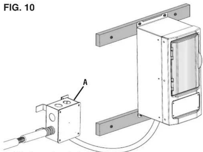
natural_image
Technical line drawing of a mechanical assembly with labeled component A (no text or symbols beyond label)A - Receptáculo
FIG. 14
natural_image
3D technical illustration of an enclosure with internal components and wiring, no visible text or symbolsnatural_image
Technical line drawing of a device enclosure with internal components and wiring, shown from two orthogonal views (no text or symbols)ADVERTENCIA
natural_image
Technical line drawing of an electrical enclosure and its internal circuit board (no text or symbols)
Westinghouse
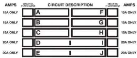
FIG. 17
A - Disyuntor de 120 V
B - Orejeta
C - Alambre caliente
FIG. 18

A - Selector de circuito
MWE Investments, LLC.
777 Manor Park Drive
Columbus, OH 43228
www.WestinghouseOutdoorPower.com
Servicio al cliente
electrónico: service@wpowereq.com
WMTS30A10C
COMMUTATEUR DE TRANSFERT MANUEL
30 AMP/ 8 CIRCUITS
MANUEL DE L'UTILISATEUR
NE PAS RETOURNER CE PRODUIT AU MAGASIN
Warranty registration
777 Manor Park Drive
Columbus, OH 43228
AVOIR DES QUESTIONS?
service@wpowereq.com
Using a generator indoors CAN KILL YOU IN MINUTES. Generator exhaust contains carbon monoxide. This is a poison you cannot see or smell.
NEVER use inside a home or garage, EVEN IF doors and windows are open.


Only use OUTSIDE and far away from windows, doors, and vents.
NOTE: If you are unsure about the voltage requirement for a device connected to a branch circuit, remove that device before connecting the branch circuit to the transfer switch.
natural_image
Technical diagram of a mechanical assembly with labeled component A, showing wiring and mounting bracket (no text or symbols beyond label)natural_image
Technical line drawing of a mechanical assembly with labeled component A (no text or symbols beyond label)A - Réceptacle
FIG. 14
natural_image
3D technical illustration of a mechanical or electrical enclosure with internal components and wiring (no text or symbols)natural_image
Technical line drawing of a device enclosure with internal components and wiring, no text or symbols presentMWE INVESTMENTS, LLC GARANTIE LIMITÉE DE 5 ANS
RESPONSABILITÉ DU PROPRIÉTAIRE
RESPONSABILITÉ DE MWE INVESTMENTS, LLC
MWE Investments, LLC.
777 Manor Park Drive
Columbus, OH 43228
www.WestinghouseOutdoorPower.com
Courriel : service@wpowereq.com

natural_image
White crown icon inside a circle on a dark blue background (no text or symbols)www.WestinghouseOutdoorPower.com
Service Hotline: (855) 944-3571
777 Manor Park Drive
Columbus, OH 43228
and Westinghouse are trademarks of Westinghouse Electric Corporation.
Used under license by MWE Investments, LLC.
© 2023 MWE Investments, LLC All Rights Reserved.

- WMTS30A10C
- MANUAL TRANSFER SWITCH
- INTRODUCTION
- DISCLAIMERS
- ALL RIGHTS RESERVED
- UPDATES
- PRODUCT REGISTRATION
- For Your Records
- Westinghouse Outdoor Power
- TRANSFER SWITCH
- POWER INLET BOX
- NOTICE
- HAVE QUESTIONS?
- Email us at service@wpowereq.com
- or call 1-855-944-3571
- SAFETY DEFINITIONS
- SAFETY SYMBOLS
- IMPORTANT SAFETY INSTRUCTIONS
- DANGER
- WARNING
- SAFETY INSTRUCTIONS FOR USING PORTABLE GENERATORS
- ELECTRICAL
- CHOOSING LOAD AND TRANSFER CIRCUITS
- WATTAGE CAPACITY
- UNDERSTANDING YOUR TOOL
- See Figure 1.
- CIRCUIT BREAKERS
- CIRCUIT SELECTORS
- CAUTION
- ASSEMBLY
- REMOVING CARTON CONTENTS
- INCLUDED LIST
- See Figure 2.
- WATTAGE METER
- OVERVIEW
- See Figure 3.
- INSTALLATION
- MOUNTING THE TRANSFER SWITCH
- See Figures 4 - 9.
- INSTALL ELECTRICAL JUNCTION BOX (NOT INCLUDED)
- See Figure 10.
- MOUNTING THE POWER INLET BOX
- See Figures 11 - 14.
- WIRING THE TRANSFER SWITCH TO THE LOAD CENTER
- To complete installation:
- OPERATION
- OPERATING/TESTING THE TRANSFER SWITCH
- See Figures 21 - 24.
- To test/operate the transfer switch in the "LINE" position:
- ! DANGER
- RESETTING THE TRANSFER SWITCH'S CIRCUIT BREAKERS
- See Figure 25.
- To reset a circuit breaker:
- LIMITED WARRANTY STATEMENT
- OWNER'S RESPONSIBILITY
- MWE INVESTMENTS, LLC'S RESPONSIBILITY
- DO NOT RETURN THE UNIT TO THE PLACE OF PURCHASE
- EXCLUSIONS
- Normal Wear Items
- Installation, Use and Maintenance
- ADDITIONAL EXCLUSIONS
- This warranty excludes:
- LIMITS OF IMPLIED WARRANTY AND CONSEQUENTIAL DAMAGE
- CONTACT INFORMATION
- Address
- Customer Service
- INTERRUPTOR DE TRANSFERENCIA MANUAL
- MANUAL DE USUARIO
- NO DEVUELVA ESTE PRODUCTO A LA TIENDA
- INSTALE LA CAJA DE CONEXIONES ELÉCTRICAS (NO INCLUIDA))
- Vea la figura 10.
- ADVERTENCIA
- Servicio al cliente
- COMMUTATEUR DE TRANSFERT MANUEL
- MANUEL DE L'UTILISATEUR
- NE PAS RETOURNER CE PRODUIT AU MAGASIN
- RESPONSABILITÉ DU PROPRIÉTAIRE
- RESPONSABILITÉ DE MWE INVESTMENTS, LLC
Brand : WESTINGHOUSE
Model : WMTS30A10C
Category : Generator