iGen4500s - Generator WESTINGHOUSE - Free user manual and instructions
Find the device manual for free iGen4500s WESTINGHOUSE in PDF.

User questions about iGen4500s WESTINGHOUSE
0 question about this device. Answer the ones you know or ask your own.
Ask a new question about this device
Download the instructions for your Generator in PDF format for free! Find your manual iGen4500s - WESTINGHOUSE and take your electronic device back in hand. On this page are published all the documents necessary for the use of your device. iGen4500s by WESTINGHOUSE.
USER MANUAL iGen4500s WESTINGHOUSE
Digital Inverter Generators Instruction Manual
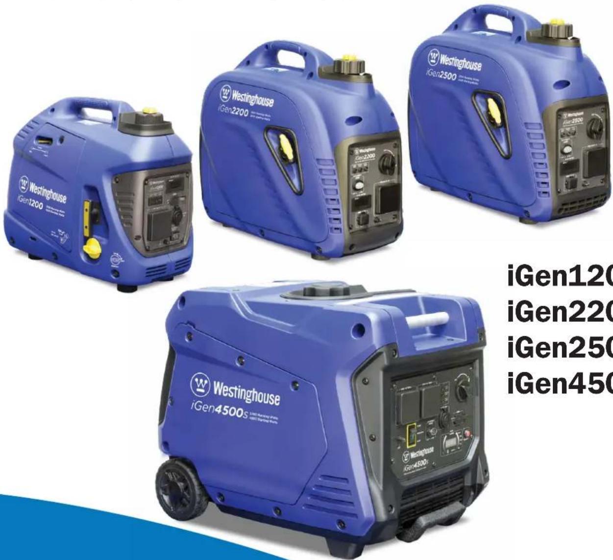
iGen1200
iGen2200
iGen2500
iGen4500s
CONGRATULATIONS ON PURCHASING A WESTINGHOUSE DIGITAL INVERTER GENERATOR
Thank you for purchasing a Westinghouse portable generator. It is a high-quality power product that will provide many years of safe and reliable service if properly operated and maintained.
DANGER

This manual contains important instructions for operating the generator. For your safety and that of others, be sure to read this manual thoroughly before operating the generator. Failure to properly follow all instructions and precautions could cause you or others to be seriously hurt or killed. This manual should be considered a permanent part of the generator and should remain with it if resold.
For Your Records:
Date of Purchase: ____
Generator Model Number:
Purchased From: ____
Generator Serial Number: ____
Purchase Receipt: Please retain your tax invoice or purchase receipt to ensure warranty coverage.
DISCLAIMERS:
All instructions, illustrations and specifications in this manual are based on the latest information available at the time of publishing. The illustrations used in this manual are intended as representative reference views only. Moreover, because of our continuous product improvement policy, we may modify information, illustrations or specifications to explain or exemplify a product, service or maintenance improvement. We reserve the right to make any change at any time without notice. Your generator may differ slightly from the models pictured, including optional accessories.
ALL RIGHTS RESERVED:
No part of this publication may be reproduced or used in any form by any means – graphic, electronic or mechanical, including photocopying, recording, taping or information storage and retrieval systems – without the written permission of Westinghouse Outdoor Power Equipment.
SAFETY....1
SAFETY DEFINITIONS ....1
SAFETY SYMBOL DEFINITIONS....1
GENERAL SAFETY RULES....2
SAFETY LABELS......4
UNPACKING....5
UNPACKING THE GENERATOR....5
ACCESSORIES....5
FEATURES......6
MAIN GENERATOR COMPONENTS iGen1200....6
CONTROL PANEL FEATURES iGen1200 7
MAIN GENERATOR COMPONENTS iGen2200 & 2500 ....8
CONTROL PANEL FEATURES iGen2200 & 2500....9
MAIN GENERATOR COMPONENTS iGen4500s....10
CONTROL PANEL FEATURES iGen4500s ....11
OPERATION 13
CONNECTING THE BATTERY iGen4500s....13
BEFORE STARTING THE GENERATOR....14
CHECKING OR ADDING ENGINE OIL AND FUEL 15
Checking and Adding Engine Oil....15
Checking and Adding Fuel....15
STARTING THE GENERATOR....16
iGen1200 Starting....16
iGen2200 & 2500 Starting....17
iGen4500s Electric Starting....18
iGen4500s Manual Starting....18
iGen4500s Wireless Remote Starting....19
iGen4500s Pairing the Remote Control Fob and Generator....19
ECO THROTTLE CONTROL 19
OVERLOAD RESET 20
STOPPING THE GENERATOR....20
Normal Operation....20
During an Emergency....20
APPLICATION AND DUTY CYCLE....20
AMBIENT CONDITIONS....21
CONNECTING ELECTRICAL LOADS 21
240-Volt AC Loads....21
12-Volt DC Accessory Loads 21
5-Volt DC USB Loads 21
Power Output and Demand 22
240-VOLT AC EXTENSION CORDS....23
12 VOLT BATTERY CHARGING....23
Battery Charging by Direct Connection 23
Battery Charging by a Mains-Powered Charger....24
TRANSPORTING THE GENERATOR....25
MAINTENANCE....26
MAINTENANCE PRECAUTIONS 26
Maintenance Schedule....26
ENGINE OIL MAINTENANCE....27
Engine Oil Specification 27
Checking Engine Oil....27
Adding Engine Oil....28
Changing Engine Oil....28
AIR FILTER MAINTENANCE 29
Cleaning the Air Filter 29
FUEL STRAINER MAINTENANCE 30
SPARK PLUG MAINTENANCE ....31
SPARK ARRESTER MAINTENANCE 33
CLEANING THE GENERATOR....34
12 VOLT BATTERY MAINTENANCE iGen4500s....34
Charging the Battery 34
Replacing the Battery....35
REMOTE CONTROL FOB MAINTENANCE 35
DRAINING THE FUEL....35
LONG-TERM STORAGE 36
Storage Procedure for 1 – 3 Months ....36
Storage Procedure for Greater than 3 Months....37
Removal from Storage 37
DISMANTLING AND DISPOSAL....37
TROUBLESHOOTING....38
SPECIFICATIONS......42
WIRING DIAGRAMS 43
iGen1200 WIRING DIAGRAM 43
iGen2200 & 2500 WIRING DIAGRAM....44
iGen4500s WIRING DIAGRAM 45
WARRANTY......46
WARRANTY AGAINST DEFECTS....46
Proof of Purchase 46
Warranty Conditions 46
SAFETY DEFINITIONS
The words DANGER, WARNING, CAUTION and NOTICE are used throughout this manual to highlight important information. Be certain that the meanings of these alerts are known to all who work on or near the equipment.

This safety alert symbol appears with most safety statements. It means attention, become alert, your safety is involved! Please read and abide by the message that follows the safety alert symbol.

DANGER
Indicates a hazardous situation which, if not avoided, will result in death or serious injury.

WARNING
Indicates a hazardous situation which, if not avoided, could result in death or serious injury.

CAUTION
Indicates a hazardous situation which, if not avoided, could result in minor or moderate injury.
NOTICE
Indicates a situation which, if not avoided, could cause damage to the generator, personal property or the environment, or cause the equipment to operate improperly.
NOTE: Indicates a procedure, practice or condition that should be followed in order for the generator to function in the manner intended.
SAFETY SYMBOL DEFINITIONS
| Symbol Description | |
 | Safety Alert Symbol |
 | Asphyxiation Hazard |
 | Burn Hazard |
 | Burst / Pressure Hazard |
 | Don’t Leave Tools Around |
 | Electrical Shock Hazard |
 | Explosion Hazard |
 | Fire Hazard |
 | Lifting Hazard |
 | Pinch-Point Hazard |
 | Read Manufacturer’s Instructions |
 | Wear Personal Protective Equipment (PPE) |
 | Read Safety Messages Before Proceeding |
GENERAL SAFETY RULES
DANGER

Never use the generator in a location that is wet or damp. Never expose the generator to rain, snow, water spray or standing water while in use. Protect the generator from all hazardous weather conditions. Moisture or ice can cause a short circuit or other malfunction in the electrical system.

Never operate the generator in an enclosed area. Engine exhaust contains carbon monoxide. Only operate the generator outside and away from windows, doors and vents.
WARNING

Voltage produced by the generator could result in death or serious injury.
- Never operate the generator in rain or a floodplain unless proper precautions are taken to avoid being subject to rain or flood.
- Never use worn or damaged extension cords.
• Always have a licensed electrician connect the generator to any fixed electrical installation. - Never touch an operating generator if the generator is wet or if you have wet hands.
- Never operate the generator in highly conductive areas such as around metal decking or steel works.
- Always use earthed extension cords. Always use three-wire or double-insulated power tools.
- Never touch live terminals or bare wires while the generator is operating.
- Keep animals and children away from the generator at all times.
WARNING

Petrol fuel liquid and vapours are extremely flammable and explosive under certain conditions.
• Always refuel the generator outdoors, in a well-ventilated area.
- Never remove the fuel cap while the engine is running.
- Never refuel the generator while the engine is running. Always turn engine off and allow the generator to cool before refuelling.
- Only fill fuel tank with unleaded petrol.
- Keep away from sparks, open flames or other forms of ignition such as matches, cigarettes, CB radios and mobile phones when refuelling.
- Never overfill the fuel tank. Leave room for fuel to expand. Overfilling the fuel tank can result in a sudden overflow of fuel and result in spilled fuel coming in contact with hot surfaces. Spilled fuel can ignite. If fuel is spilled on the generator, wipe it up immediately and dispose of rags properly. Allow area of spilled fuel to dry before operating the generator.
- Wear eye protection while refuelling.
- Never use fuel as a cleaning agent.
- Store any fuel containers in a well-ventilated area, away from any combustibles or source of ignition.
- Check for fuel leaks after refuelling. Never operate the engine if a fuel leak is discovered.
- Equip the operating area with a Class ABE or BE portable fire extinguisher.
WARNING
Never operate the generator if: powered items overheat; electrical output drops; there are sparks, flames or smoke coming from the generator; or if the receptacles are damaged.
Never attempt to connect more than one generator to the same electrical device, extension cord or fixed electrical installation.

Never use the generator to power medical support equipment.

Always remove any tools or other service equipment used during maintenance before operating the generator.
WARNING

You must take reasonable care for the health and safety both of yourself and any others who may be affected by your actions. You must understand and follow all of the safety rules and working instructions described herein. You must also use your own good judgement and common sense.
NOTICE
Never modify the generator.
Never operate the generator if it vibrates at high levels, if the engine speed changes greatly or if the engine misfires often.
Always disconnect electric tools or appliances from the generator before starting.
WARNING

Do not operate in a hazardous location, e.g. where there may be a risk of explosion of fumes, leaking fuel or explosive dusts.

Do not operate in a confined area where exhaust gases, smoke or fumes could reach dangerous concentrations.

Do not refuel while engine is running.
WARNING

The generator may be started accidentally by remote control if it is left unintentionally in the Auto-Run mode.
- Always keep the remote control fob secure to prevent accidental starting of the generator.
- Never leave the generator on non-operating standby in Auto-Run mode unless intentionally required.
- Do not start the generator by remote control unless you have it in clear sight or are otherwise sure that it is safe to do so.
SAFETY LABELS
The safety labels have specific positions and must be replaced if they are unreadable, damaged or missing.

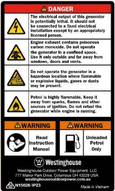
text_image
Westinghouse iGen1200 Westinghouse iGen2200 Westinghouse iGen2500 Westinghouse iGen4500sFigure 1 - Safety Labels
①
text_image
DANGER The electrical output of this generator is potentially lethal. It should not be connected to a fixed electrical installation except by an appropriately licensed person. Engine exhaust contains poisonous carbon monoxide. Do not operate the generator in a confined space. Use it only outside and far away from windows, doors and vents. Do not operate the generator in a hazardous location where flammable or explosive liquids, gases or dusts may be present. Petrol is highly flammable. Keep it away from sparks, flames and other sources of ignition. Do not refuel the generator while engine is running. WARNING Read Instruction Manual WARNING Unleaded Petrol Only Westinghouse Westinghouse Outdoor Power Equipment, LLC T77 Manor Park Drive, Columbus DH 43228 USA westinghouseoutdoorpower.com.au N15626 IP23 Made in Vietnam②

text_image
WARNING Hot Surface③

text_image
WARNING Hot SurfaceUNPACKING THE GENERATOR
WARNING

Always have assistance when lifting the generator. The generator is heavy; lifting it could cause bodily harm.

Avoid cutting on or near staples to prevent personal injury.
- Carefully cut the packing tape on top of the carton.
- Fold back top flaps to reveal the upper packing tray.
- Remove and save the instruction manual, oil bottle, oil funnel and spark plug socket wrench.
- Remove and discard the upper packing tray.
- Unfold the top of the plastic bag enclosing the generator.
- iGen1200, 2200 & 2500: Lift the generator out of the plastic bag and carton.
iGen4500s: Carefully cut the vertical corners of the carton to access the generator. - Recycle or dispose of the packaging materials properly.
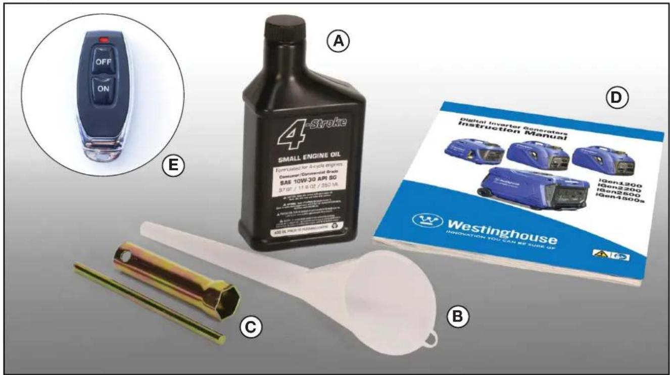
ACCESSORIES
Check the accessories against those shown in Figure 2. If any parts are missing, please contact your local Westinghouse dealer.
A – Bottle of SAE 10W-30 Engine Oil (250 ml for iGen1200, 350 ml for iGen2200 & 2500, and 600 ml for iGen4500s)
B - Oil Funnel
C - Spark Plug Socket Wrench
D - Instruction Manual
E - Remote Control Fob (for iGen4500s)
text_image
OFF ON A E 4-Stroke SMALL ENGINE OIL Formulated for 4-cycle engines Consumer Commercial Trade SAE 10W-30 API SG 37.07 / 11.6 oz / 200 MA C D Digital Inverter Generators Instruction Manual IGen1200 IGen2200 IGen2500 IGen4500s WESTINGHOUSE INNOVATION YOU CAN BE SURE UP BFigure 2 - Accessories
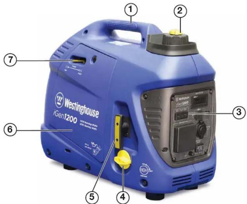
MAIN GENERATOR COMPONENTS iGen1200
text_image
Westinghouse iGen1200 1200 Washing of 60% SPC (80%) 2 3 4 5 6 7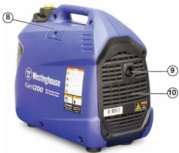
text_image
Westinghouse iGen1200 1300 Heating MWh 305 Heating MWh ⑧ ⑨ ⑩1 - Carry Handle
2 - Fuel Cap and Vent
3 - Control Panel
4 - Engine and Fuel Control Switch
5 - Recoil Starter Handle
6 - Engine Access Cover
7 - Choke Lever
8 - Spark Plug Access Cover
9 - Exhaust Pipe
10 - Muffler Access Cover
Figure 3 - iGen1200 Main Generator Components
CONTROL PANEL FEATURES iGen1200

text_image
Westinghouse i Gen 1200 HOUR METER SZB.T 5V DC 2.1A 240 VOLTS AC Efficiency MODE 0 - OFF ON Run Time (hours) SZB.T 0 168- Output Indicator: The green status light will illuminate whenever the engine is running and there is AC output available from the generator.
- Overload Alarm: The red warning light will illuminate if the generator's AC output is overloaded or short-circuited. A brief small overload may be tolerated, but the connected load should be reduced. An extended large overload or short circuit will trip the overload protection feature and disconnect the generator's AC output even though the engine is still running. Stop the engine and then re-start it to restore AC output.
- Low Oil Alarm: The red warning light will illuminate and the engine will automatically shut down if the oil level becomes too low. Add oil to the correct level before re-starting the engine.
- Hour Meter: Continuously displays the cumulative running hours whenever the generator is operating.
-
5-Volt DC, 2.1-Amp USB Outlet: Suitable for charging electronic devices such as phones, tablets and computers with a power demand not exceeding 10 Watts.
-
12-Volt DC Accessory Socket: Can be used for 12-Volt DC powered devices up to a maximum demand of 60 Watts (i.e. 5 Amps).
- ECO Throttle Switch: Move the switch to the ON position when powering small resistive loads such as a computer or electric light; the engine speed will automatically be kept to a minimum, thereby reducing fuel consumption and noise. Select the OFF position when powering large inductive loads such as an air conditioner or electric pump; the engine speed will be kept higher for maximum electrical starting power.
- Frame Terminal: The frame terminal can be used by a licensed electrician to earth the generator if necessary.
- 240-Volt AC, 15-Amp Outlet: The outlet is capable of delivering the generator's peak output of 1,200 Watts (i.e. 5 Amps at 240 Volts).
Figure 4 - iGen1200 Control Panel Features
MAIN GENERATOR COMPONENTS iGen2200 & 2500
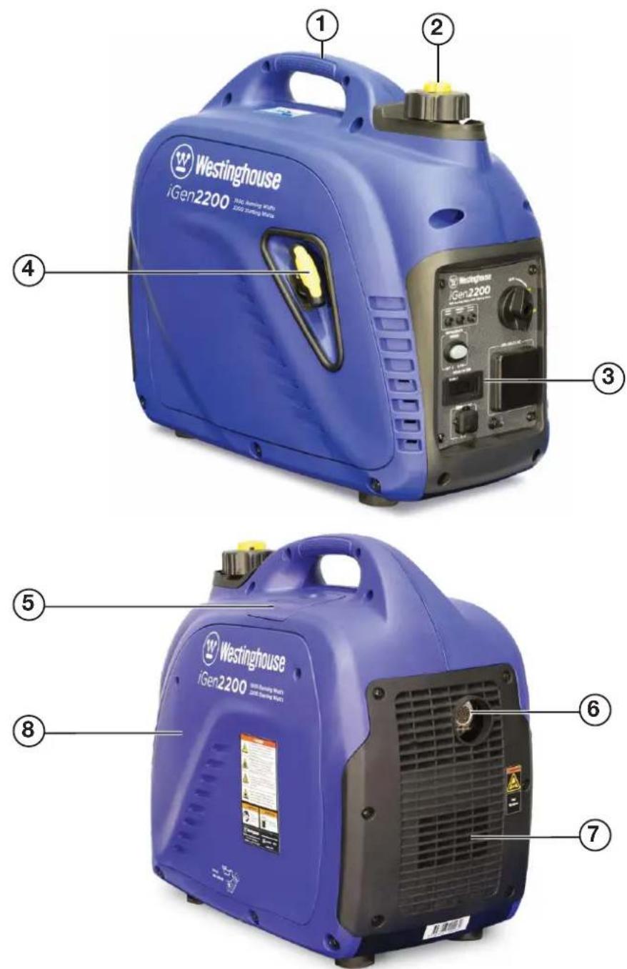
1 - Carry Handle
2 - Fuel Cap and Vent
3 - Control Panel
4 - Recoil Starter Handle
5 - Spark Plug Access Cover
6 - Exhaust Pipe with Spark Arrester
7 - Muffler Access Cover
8 - Engine Access Cover
Figure 5 - iGen2200 & 2500 Main Generator Components
CONTROL PANEL FEATURES iGen2200 & 2500

text_image
Westernhouse iGen2200 800 Running Watts 800 Starting Watts OFF ON CHORE EFFICIENCY MODE OFF ON HOUR METER 240 VOLTS AC SZB.T 0.168 Run Time (hours) ① ② ③ ④ ⑤ ⑥ ⑦ ⑧ ⑨- Output Indicator: The green status light will illuminate whenever the engine is running and there is AC output available from the generator.
- Overload Alarm: The red warning light will illuminate if the generator's AC output is overloaded or short-circuited. A brief small overload may be tolerated, but the connected load should be reduced. An extended large overload or short circuit will trip the overload protection feature and disconnect the generator's AC output even though the engine is still running. Stop the engine and then re-start it to restore AC output.
- Low Oil Alarm: The red warning light will illuminate and the engine will automatically shut down if the oil level becomes too low. Add oil to the correct level before re-starting the engine.
-
Engine, Fuel and Choke Control Switch: Tum the knob to the CHOKE position before starting the generator if its engine is cold. Select the ON position to re-start or run the generator when its engine is warm. Turning the knob to the OFF position stops the generator and cuts off the engine's fuel supply.
-
240-Volt AC, 15-Amp Outlet: The outlet is capable of delivering the generator's peak output of 2,200 Watts (iGen2200) or 2,500 Watts (iGen2500).
- Frame Terminal: The frame terminal can be used by a licensed electrician to earth the generator if necessary.
- 5-Volt DC, 2.1-Amp USB Outlet: Suitable for charging electronic devices such as phones, tablets and computers with a power demand not exceeding 10 Watts.
- Hour Meter: Continuously displays the cumulative running hours whenever the generator is operating.
- ECO Throttle Switch: Move the switch to the ON position when powering small resistive loads such as a computer or electric light; the engine speed will automatically be kept to a minimum, thereby reducing fuel consumption and noise. Select the OFF position when powering large inductive loads such as an air conditioner or electric pump; the engine speed will be kept higher for maximum electrical starting power.
Figure 6 - iGen2200 & 2500 Control Panel Features
MAIN GENERATOR COMPONENTS iGen4500s
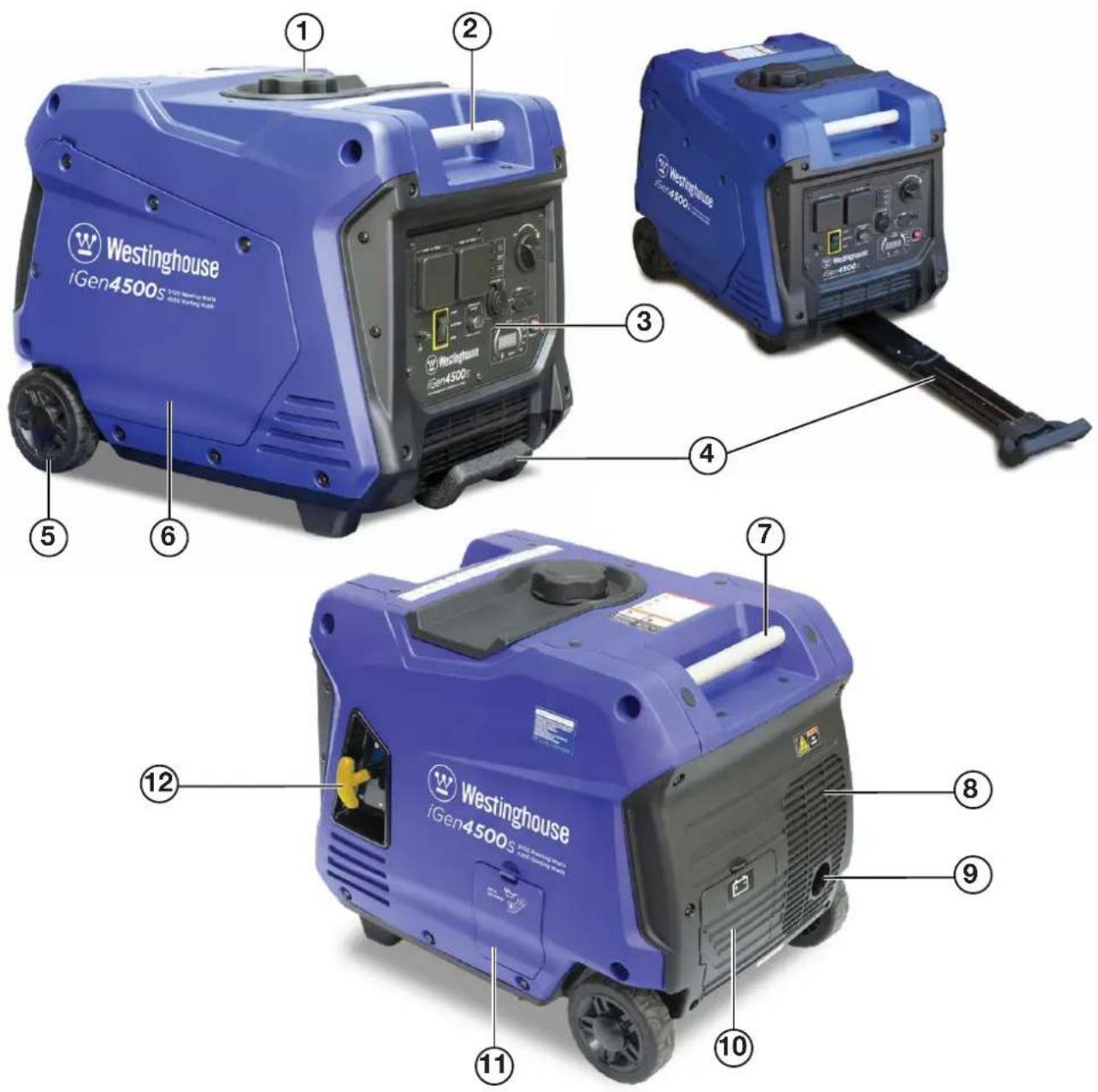
text_image
Westinghouse iGen4500s ① ② ③ ④ ⑤ ⑥ ⑦ ⑧ ⑨ ⑪ ⑩1 - Fuel Cap
2 - Front Carry Handle
3 - Control Panel
4 - Extendable Handle
5 - Wheel
6 - Engine Access Cover
7 - Rear Carry Handle
8 - Muffler Access Cover
9 - Exhaust Pipe with Spark Arrester
10 - Battery Access Cover
11 - Oil Access Cover
12 - Recoil Starter Handle
Figure 7 - iGen4500s Main Generator Components
CONTROL PANEL FEATURES iGen4500s
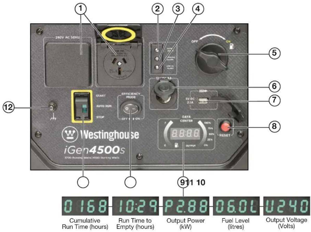
text_image
240V AC 50Hz 1 2 3 4 OFF ON 12V DC 8A START AUTO RUN STOP EFFICIENCY MODE OFF ON 5V DC 2.1A DATA CENTER 100% 75% 50% 25% E OUTPUT ON 911 10 Cumulative Run Time (hours) 10:29 Run Time to Empty (hours) P 2.88 Output Power (kW) Fuel Level (litres) U 6.0L Output Voltage (Volts)Figure 8 - iGen4500s Control Panel Features
- 240-Volt AC, 15-Amp Outlets: Each outlet is capable of delivering the generator's peak output of 4,500 Watts (i.e. 18.8 Amps at 240 Volts) intermittently. Continuous supply from a single outlet should not exceed 3,600 Watts (i.e. 15 Amps at 240 Volts).
- Output Indicator: The green status light will illuminate whenever the engine is running and there's AC output available from the generator.
-
Overload Alarm: The red warning light will illuminate if the generator's AC output is overloaded or short-circuited. A brief small overload may be tolerated, but the connected load should be reduced. An extended large overload or short circuit will trip the overload protection feature and disconnect the generator's AC output even though the engine is still running. Reduce the connected load or rectify the electrical fault before pressing the generator reset button to restore AC output.
-
Low Oil Alarm: The red warning light will illuminate and the engine will automatically shut down if the oil level becomes too low. Add oil to the correct level before re-starting the engine.
- Fuel Control Switch: Turn the knob to the ON position before starting the generator. Turn to the OFF position after stopping the engine with the engine control switch for routine shut down. Or select the OFF position and allow the engine to run out of fuel prior to long-term shut down.
- 12-Volt DC Accessory Socket: Can be used for 12-Volt DC powered devices up to a maximum demand of 100 Watts (i.e. 8 Amps).
-
5-Volt DC, 2.1-Amp USB Outlet: Suitable for charging electronic devices such as phones, tablets and computers with a power demand not exceeding 10 Watts.
-
Generator Reset Button: Press and hold down this button to reset the generator's electrical output when safe to do so after reducing the applied load or rectifying the electrical fault that has caused an overload trip.
- Data Center: The alphanumeric LED display shows the cumulative run time, run time to empty at current load, output power, fuel level and output voltage in a repeating cycle. The curved LED graphic displays on the left and right-hand sides show the fuel level and output power, respectively.
- ECO Throttle Switch: Move the switch to the ON position when powering small resistive loads such as a computer or electric light; the engine speed will automatically be kept to a minimum, thereby reducing fuel consumption and noise. Select the OFF position when powering large inductive loads such as an air conditioner or electric pump; the engine speed will be kept higher for maximum electrical starting power.
- Engine Control Switch: When the switch is momentarily pressed to the START position and then released to the AUTO RUN position, the electric starter motor automatically engages and starts the engine. The engine will continue running whilst the switch is in the AUTO RUN position. To stop the engine, move the switch to the STOP position. The engine can also be started and stopped by remote control when the engine control switch is in the AUTO RUN position.
- Frame Terminal: The frame terminal can be used by a licensed electrician to earth the generator if necessary.
CONNECTING THE BATTERY iGen4500s
WARNING

To avoid electric shock:
- ALWAYS connect the positive (+) battery cable (red boot) first when connecting battery cables.
- ALWAYS disconnect the negative (-) battery cable (black boot) first when disconnecting battery cables.
- NEVER connect the negative (-) battery cable (black boot) to the positive (+) terminal on the battery.
- NEVER connect the positive (+) battery cable (red boot) to the negative (-) terminal on the battery.
- NEVER touch both battery terminals simultaneously.
- NEVER place a tool or other metal object across both battery terminals.
- NEVER place a tool or other metal object between either of the battery terminals and any part of the generator.
- ALWAYS use insulated or non-conducting tools when installing the battery.
NOTE: The generator comes equipped with the battery cables already attached to the battery. It is only necessary to assemble the battery wiring harness connector.
Tools required - None.
- Remove the battery access cover by pressing down on its locking tab and pulling it away from the generator (see Figure 9).
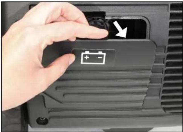
natural_image
Close-up of a hand pressing a battery button with an arrow, no visible text or symbolsFigure 9 – Opening the Battery Access Cover
- Check that the battery is positioned correctly and securely held in place by the battery strap hooked onto themountingbase(seeFigure10). Check also that the battery cables are not kinked or pinched.
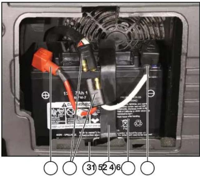
text_image
12.7 Ah 1 4.7 FM-7 PROMETER 65 WARNING 31 52 4 6 NON - SPILLAGE 31 52 4 61 - Positive (+) Battery Cable
2 - Battery Wiring Harness Connector
3 - Battery Mounting Base
4 - Battery Strap
5 - Battery
6 - Negative (-) Battery Cable
Figure 10 – Battery Mounting Inside Generator
- Locate the two halves of the battery wiring harness connector.
- Assemble the connector by firmly pushing the two halves together; each of the two male pins should be inserted into the corresponding female socket on the other half of the connector as shown in Figure 11. The connector should be assembled tightly with no appreciable gap left between the two halves.
- Replace the battery access cover.

text_image
Close-up of hands installing a battery component with Chinese annotations indicating installation stepsFigure 11 – Assembling the Battery Wiring Harness Connector
BEFORE STARTING THE GENERATOR
Location Selection – Before starting the generator, avoid exhaust and location hazards by verifying that:
- You have selected a location to operate the generator that is outdoors and well ventilated.
- You have selected a location with a level and solid surface on which to place the generator.
- You have selected a location that is at least 1.8 m away from any building, other equipment or combustible material.
- If the generator is located close to a building, it is not located near any windows, doors or vents.
text_image
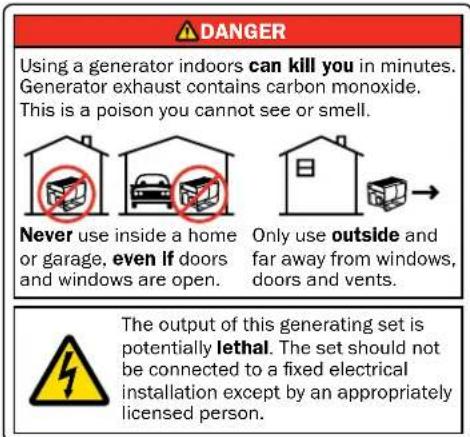
DANGER Using a generator indoors can kill you in minutes. Generator exhaust contains carbon monoxide. This is a poison you cannot see or smell. Never use inside a home or garage, even if doors and windows are open. Only use outside and far away from windows, doors and vents. The output of this generating set is potentially lethal. The set should not be connected to a fixed electrical installation except by an appropriately licensed person.
text_image
WARNING Always operate the generator on a level surface. Placing the generator on a non-level surface can cause the generator to tip over, causing fuel and oil to spill. Spilt fuel can ignite if it comes into contact with an ignition source such as a very hot surface.
text_image
NOTICE Only operate the generator on a solid, level surface. Operating the generator on a surface with loose material such as sand or grass clippings can cause debris to be ingested by the generator that could: • Block cooling vents • Block air intake system| NOTICE |
| Ensure that the generator is always kept horizontal during handling, operation, storage and transport. Flipping the generator over onto its side, end or top will damage it. |
Weather – Never operate your generator outdoors during rain, snow or any combination of weather conditions that could lead to moisture collecting on, in or around the generator.
Dry Surface – Always operate the generator on a dry surface free of any moisture.
No Connected Loads – Make sure the generator has no connected loads before starting it. To ensure there are no connected loads, either unplug any electrical cords or devices from the 240-Volt AC, 12-Volt DC accessory and 5-Volt DC USB receptacles on the control panel or check that they are switched off.
NOTICE
Starting the generator with loads already connected to it could result in damage to any device being powered by the generator during the brief start-up period.
Earthing the Generator – The generator's equipotential bonding system including the frame terminal on the control panel should not be connected to the general mass of earth through a separate earth electrode. For more information, refer to AS/NZS 3010:2017 Electrical Installations – Generating Sets or consult a licensed electrician.
WARNING

Be sure the generator is properly installed to reduce the possibility of electric shock. Any connection to an electrical installation such as in a building, for example, must be carried out by a licensed electrician.
CHECKING OR ADDING ENGINE OIL AND FUEL
DANGER

Filling the fuel tank with fuel while the generator is running can cause fuel to spill and come in contact with hot surfaces that can ignite the fuel.
Before starting the generator, always check the engine oil and fuel levels.
After starting the generator, it is not safe to add fuel to the fuel tank or engine oil to the engine while the engine is running or immediately after stopping while the engine and muffler are still hot.
Checking and Adding Engine Oil
WARNING

Internal pressure can build up in the engine crankcase while the engine is running. Removing the oil fill plug while the engine is hot can cause hot oil to spray out of the crankcase and cause severe skin burns. Allow engine oil to cool for several minutes before removing the oil fill plug.
The generator as shipped does not contain oil in the engine. You must add engine oil before starting the generator for the first time. See Checking Engine Oil and Adding Engine Oil for instructions on checking engine oil level and the procedure for adding engine oil.
NOTICE
The generator does not contain engine oil as shipped. Attempting to start the engine before adding engine oil can permanently damage internal engine components.
Checking and Adding Fuel
WARNING

Never refuel the generator while the engine is running.

Always turn the engine off and allow the generator to cool before refuelling.
With the generator switched off and stationary on a horizontal surface, check the fuel level in the tank visually by removing the fuel cap. It is good practice to always fill the fuel tank before operating the generator.
Required Fuel – Use only unleaded petrol with an octane rating not less than 91 and ethanol content not greater than 10%. Where possible it is preferable to use regular unleaded petrol without ethanol.
Filling the Fuel Tank – Follow the steps below to fill the fuel tank:
- Stop the generator, if running.
- Allow the generator to cool down until the muffler access cover is cool to the touch.
- Move the generator to a flat surface.
- Clean area around the fuel cap.
-
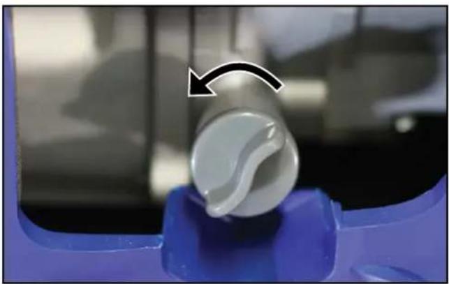
Turn the fuel cap vent clockwise to the ON position (not applicable to the iGen4500s).
-
Remove the fuel cap by unscrewing it anticlockwise.
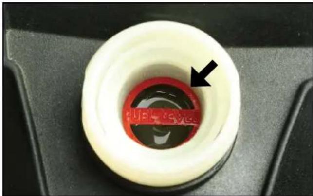
- Slowly add fuel into the fuel tank. Be careful not to overfill the tank. The fuel level should NOT be higher than the red ring inside the fuel strainer (see Figure 12).
- Replace the fuel cap by screwing it on clockwise and turn the fuel cap vent anti-clockwise to the OFF position (if equipped).
natural_image
Close-up of a white plastic ring with red liquid and a black arrow pointing to the center (no text or symbols visible)Figure 12 – Maximum Fuel Fill Level
CAUTION

Avoid prolonged skin contact with fuel. Avoid prolonged inhalation of fuel vapours.
NOTICE
Do not overfill the fuel tank. Spilt fuel may damage some plastic parts.
STARTING THE GENERATOR
Before attempting to start the generator, verify the following:
- The engine is filled with engine oil (see Checking Engine Oil).
- The generator is situated in a proper location (see Location Selection).
- The generator is on a dry surface (see Weather and Dry Surface).
- All loads are disconnected from the generator or switched off (see No Connected Loads).
DANGER
Never use the generator in a location that is wet or damp. Never expose the generator to rain, snow, water spray or standing water while in use. Protect the generator from all hazardous weather conditions. Moisture or ice can cause a short circuit or other malfunction in the electrical system.

Never operate the generator in an enclosed area. Engine exhaust contains carbon monoxide. Only operate the generator outside and away from windows, doors and vents.
NOTICE
The generator is equipped with a low oil shutdown switch. If the oil level becomes too low, the engine will shut down automatically and cannot be re-started until the oil is filled to the proper level.
Be sure the engine has the proper oil level before using. Failure to verify that the engine has the proper oil level could result in severe engine damage or shorten the engine life.
Disconnect or switch off all loads from the generator before starting. Failure to verify all loads are disconnected prior to starting the generator could result in damage to the connected electrical devices.
iGen1200 Starting
The primary touch points that the user needs to interact with when starting the generator are identified with yellow coloured markings.
- Turn the fuel cap vent to the ON position (see Figure 13).
natural_image
Close-up of a yellow rotary knob with 'ON' and 'OFF' labels, no readable text or symbols beyond the directional arrowFigure 13 – Fuel Cap Vent in the ON Position
- Turn the engine and fuel control switch anti-clockwise to the ON position (see Figure 14).

text_image
ON OFF ENGINEFigure 14 – Engine and Fuel Control Switch in the ON Position
- Move the choke lever rightwards to the START position if starting a cold engine (see Figure 15). To re-start a warm engine, leave the choke lever pushed left to the RUN position.

text_image
CHoke RUN STARTFigure 15 – Choke Lever in the START Position
- Whilst holding the generator down with one hand, firmly grasp the recoil starter handle with your other hand and pull it slowly until you feel increased resistance. At this point, pull it briskly up and away from the generator (see Figure 16). Do not allow the starter handle to snap back against the engine, but instead return it gently to prevent starter damage. Do not allow the starter cord to rub against other parts of the generator.
- As the engine starts running and warms up, gradually move the choke lever leftwards to the RUN position.
- Connect electrical cords or devices into the 240-Volt AC, 12-Volt DC accessory or 5-Volt DC USB outlets, as required.

natural_image
Close-up of a hand holding a black and yellow plastic device attached to a blue industrial component (no visible text or symbols)Figure 16 – Recoil Starter Handle Operation
iGen2200 & 2500 Starting
- Turn the fuel cap vent to the ON position (see Figure 13).
- Turn the engine, fuel and choke control switch clockwise to the CHOKE position if starting a cold engine (see Figure 17). To re-start a warm engine, turn the knob to the ON position.
text_image
OFF ON CHOKE 0 WattsFigure 17 – Engine, Fuel and Choke Control Switch in the CHOKE Position
3 Whilst holding the generator down with one hand, firmly grasp the recoil starter handle with your other hand and pull it slowly until you feel increased resistance. At this point, pull it briskly up and away from the generator (see Figure 16). Do not allow the starter handle to snap back against the engine, but instead return it gently to prevent starter damage. Do not allow the starter cord to rub against other parts of the generator.
4. As the engine starts running and warms up, turn the engine, fuel and choke control switch anticlockwise to the ON position.
5. Connect electrical cords or devices into the 240-Volt AC, 12-Volt DC accessory or 5-Volt DC USB outlets, as required.
iGen4500s Electric Starting
- Turn the fuel control switch clockwise to the ON position (see Figure 18).

text_image
OFF ONFigure 18 – Fuel Control Switch in the ON Position
- Momentarily push the engine control switch to the START position for at least one second and then release it to the AUTO RUN position whereupon the electric starter motor will automatically engage and start the engine. The engine will continue running whilst the switch is in the AUTO RUN position (see Figure 19).
text_image
START AUTO RUN STOPFigure 19 – Engine Control Switch in the AUTO RUN Position
NOTICE
Failure to promptly release the engine control switch to the AUTO RUN position will inhibit the automatic starting sequence. Push the engine control switch to the STOP position and then repeat the starting procedure.
Never push the engine control switch to the START position while the engine is running; this will cause the generator to stop and may cause damage to any connected electrical devices.
NOTE: If the engine fails to start on the first attempt, it will automatically retry a second time without any operator intervention. If the engine fails to start after both attempts, push the engine control switch to the STOP position and then refer to the TROUBLESHOOTING instructions.
NOTE: The electric start generator is equipped with a battery charging feature. Once the engine is running, a small charge is supplied to the battery via the battery cables that will slowly recharge the battery.
NOTE: There is no need to alter this starting procedure dependent upon the engine temperature. The iGen4500s is equipped with an automatic choke.
- Connect electrical cords or devices into the 240-Volt AC, 12-Volt DC accessory or 5-Volt DC USB outlets, or switch them on if already connected, as required.
iGen4500s Manual Starting
NOTE: It is not possible to manually start the generator if the battery is not connected or completely discharged (flat). Ensure that the battery is installed and connected before attempting to manually start the generator. Even though the battery may not have sufficient charge to crank the engine using the electric starter, it can still have enough charge to operate the automatic choke and permit manual starting. If the battery is completely discharged or flat, it will need to be either re-charged or replaced with a charged unit before the generator can be started.
- Turn the fuel control switch clockwise to the ON position (see Figure 18).
- Push the engine control switch to the central AUTO RUN position (see Figure 19).
- Firmly grasp the recoil starter handle with your hand and pull it slowly until you feel increased resistance. At this point, pull it briskly up and away from the generator (see Figure 16). Do not allow the starter handle to snap back against the engine, but instead return it gently to prevent starter damage. Do not allow the starter cord to rub against other parts of the generator.
- Repeat Step 3 at approximately three-second intervals until the engine starts running.
- Connect electrical cords or devices into the 240-Volt AC, 12-Volt DC accessory or 5-Volt DC USB outlets, or switch them on if already connected, as required.
iGen4500s Wireless Remote Starting
NOTE: The supplied remote control fob has already been paired with the generator and is ready for use. If it does not function properly or needs to be replaced or reprogrammed, see Pairing the Remote Control Fob and Generator. The generator can only be paired to work with one remote control fob at any given time.
NOTE: Subject to the remote control's battery condition and environmental factors such as interference, it can start the generator at a range of up to approximately 50 metres and stop the generator at up to half this distance.
- Turn the fuel control switch clockwise to the ON position (see Figure 18).
- Push the engine control switch to the central AUTO RUN position (see Figure 19).
- Point the remote control fob in the direction of the generator and momentarily press the remote control's ON button for at least one second and then release it (see Figure 20). The electric starter motor will automatically engage and start the engine, which will continue running whilst the engine control switch is in the AUTO RUN position (see Figure 19).
NOTE: If the engine fails to start on the first attempt, it will automatically retry a second time without any operator intervention. If the engine fails to start after both attempts, push the engine control switch to the STOP position and then refer to the TROUBLESHOOTING instructions.
- Connect electrical cords or devices into the 240-Volt AC, 12-Volt DC accessory or 5-Volt DC USB outlets, or switch them on if already connected, as required.
NOTE: When the generator is left in the standby condition with its engine control switch in the AUTO RUN position, but the engine not running, there is a small power drain on the battery that will cause it to slowly discharge. Depending on the battery's condition and the ambient temperature, it can remain in this standby condition for up to five days and still have sufficient charge to start the generator upon command from the remote control.

text_image
① OFF ② ON ③1 - Indicator Light
2 - OFF Button
3 - ON Button
Figure 20 - Wireless Remote Control Fob
iGen4500s Pairing the Remote Control Fob and Generator
If the remote control fob needs to be replaced or reprogrammed, you can pair it to communicate with the generator by following this procedure.
- Check that the generator is switched off and its engine is not running.
- Bring the remote control close to the generator's control panel.
- Push and hold the generator's engine control switch in the START position and simultaneously push and hold the remote control's OFF button; the remote control's red indicator light should be illuminated at first, and then shortly after when it extinguishes release both the engine control switch and the OFF button.
- The remote control fob and generator are now paired and ready for use together.
ECO THROTTLE CONTROL
The generator is equipped with ECO Throttle Control to minimise fuel consumption. In ECO mode, the generator senses the electrical load demand and adjusts the engine speed and power output to match it; if there is no electrical load connected, the engine speed drops down to idle. ECO mode should only be used once the generator has reached normal operating temperature after running for at least five minutes. When starting large inductive loads such as an air conditioner or pump, ECO mode should be switched off so that the engine speed will be kept higher for maximum electrical starting power availability.
To activate ECO mode, move the ECO throttle switch to the ON position (see Figure 21).
text_image
EFFICIENCY MODE RUN O - OFF ONFigure 21 - ECO Throttle Switch in the ON Position
To deactivate ECO mode, move the ECO throttle switch to the OFF position.
OVERLOAD RESET
An electrical overload or short circuit will trip the overload protection system by disconnecting the generator's AC output even though the engine is still running. If this occurs, the overload alarm light will be illuminated red and the output indicator light will be off. The AC output can be restored as follows:
- Turn off or unplug any electrical devices or cords from the 240-Volt AC, 12-Volt DC accessory and 5-Volt DC USB receptacles on the control panel.
- iGen1200, 2200 & 2500: Stop and re-start the generator.
iGen4500s: Press the generator reset button on the control panel until the overload alarm light goes off and the output indicator light is illuminated green.
-
Check that the intended electrical running and starting loads do not exceed the generator's capacity or have a licensed electrician rectify any fault causing a short circuit in the load.
-
Reconnect any electrical devices or cords to the receptacles on the control panel and then turn on the electrical loads as required.
STOPPING THE GENERATOR
Normal Operation
During normal operation, use the following steps to stop the generator:
- Turn off or unplug any electrical cords or devices from the 240-Volt AC, 12-Volt DC accessory and 5-Volt DC USB receptacles on the control panel.
-
Allow the generator to run unloaded for at least one minute to cool and stabilise the engine and alternator temperatures.
-
iGen1200: Turn the engine and fuel control switch clockwise to the OFF position.
iGen2200 & 2500: Turn the engine, fuel and choke control switch anti-clockwise to the OFF position. iGen4500s:
(a) Push the engine control switch to the STOP position and then turn the fuel control switch to the OFF position; or
(b) Point the remote control in the direction of the generator and momentarily press the remote control's OFF button for at least one second and then release it.
WARNING
If stopping the iGen4500s by remote control, use audible or visual means to verify that the generator has actually stopped running.
Push the engine control switch to the STOP position and then turn the fuel control switch to the OFF position unless the generator is intentionally required to be on non-operating standby awaiting a start command by remote control.
- Turn the fuel cap vent anti-clockwise to the OFF position (if equipped).
During an Emergency
If there is an emergency and the generator must be stopped quickly, follow the procedure in Step 3 above with haste.
APPLICATION AND DUTY CYCLE
All models within this range of Westinghouse generators are portable, air-cooled, petrol-engine driven, self-contained units designed for independent supply of electrical power. They are ideal as a backup power supply in the event of mains power failure or as a remote area power supply for use when camping, caravanning or working out in the field.
For most common applications, users can connect a Westinghouse generator to power electrical devices by detachable plug and socket-outlet connection as described in this manual.
Westinghouse generators can also be connected to a fixed electrical installation such as in a house or business premises, for example, by a licensed electrician.
AMBIENT CONDITIONS
The generator is designed to operate within the following range of ambient conditions:
• Temperature: -5 to +40°C
• Altitude: Up to 1,000 m
Where possible, the generator should be operated in the shade to prevent additional heat load due to solar radiation.
The engine's power output will decrease by approximately 3.5% for each 300m increase in altitude above sea level. This is normal for spark-ignition engines and is attributable to the decrease in atmospheric pressure (and thus the available air for combustion) as altitude increases.
CONNECTING ELECTRICAL LOADS
The generator can be used to power (a) 240-Volt AC, 50 Hz, single phase, (b) 12-Volt DC accessory or (c) 5-Volt DC USB electrical devices.
240-Volt AC Loads
240-Volt AC devices can be connected either directly or via electrical extension cords into the 240-Volt AC outlet(s) on the generator's control panel. Lift up the spring-loaded weather resistant cover on each outlet for access to connect the electrical device or cord.
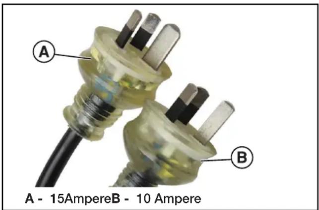
240-Volt AC devices may be fitted with either a three-pin 15 Ampere (typically abbreviated "15 Amp" or "15 A") plug or a three-pin 10 Ampere ("10 Amp" or "10 A") plug as shown in Figure 22. Certain double-insulated devices may be fitted with a two-pin 10 A plug that doesn't have an earth pin (which is the longer, vertical pin).
text_image
A - 15AmpereB - 10 Ampere A BFigure 22 - 240-Volt AC Three-Pin Plugs
NOTICE
DO NOT connect any 240-Volt AC device that is fitted with a three-pin 20 A plug. This can overload the generator.
See 240-Volt AC Extension Cords for detailed instructions concerning their selection and use.
12-Volt DC Accessory Loads (iGen1200 & 4500s)
12-Volt DC devices can be connected either directly or via an electrical extension cord not exceeding 3.5 m in length into the 12-Volt DC outlet on the generator's control panel. Pull out the weather resistant stopper on the outlet for access to connect the electrical accessory or cord, and re-insert it after use.
12-Volt DC devices or extension cords must be fitted with a cigarette lighter plug for connection to the generator as shown in Figure 23.

natural_image
Close-up of a black electric plug with a terminal pin, isolated on white background (no text or symbols visible)Figure 23 - 12-Volt DC Cigarette Lighter Plug
WARNING

Never insert an automotive cigarette lighter into the 12-Volt DC outlet. The heated lighter may ignite the fuel causing an explosion or fire.
5-Volt DC USB Loads
5-Volt DC USB devices can be connected either directly or via an electrical extension cord not exceeding 2 m in length into the 5-Volt DC USB outlet on the generator's control panel. Pull out the weather resistant stopper on the outlet for access to connect the USB device or cord, and re-insert it after use.
5-Volt DC USB devices or extension cords must be fitted with a standard Type "A" USB male plug for connection to the generator as shown in Figure 24.
The USB receptacle on the generator's control panel supplies electrical power only for charging and not any form of electronic communication, data or signal.

natural_image
Close-up of a black USB connector with gold contacts, isolated on white background (no text or symbols)Figure 24 - Type "A" USB Male Plug
Power Output and Demand
There are two limits to the amount of electric power that the generator can usefully provide: (a) its total 240-Volt AC, 12-Volt DC or 5-Volt DC electric power generating capacity or power output and (b) the electric current or power output capacity of each individual 240-Volt AC, 12-Volt DC or 5-Volt DC outlet.
The generator's total power output measured in Watts is listed in the Specifications. Two 240-Volt AC power outputs are specified for the generator, namely the running power and the starting power. The 12-Volt DC and 5-Volt DC power outputs are also specified.
NOTICE
DO NOT overload the generator's 240-Volt AC, 12-Volt DC or 5-Volt DC circuits beyond their rated capacities. This can result in damage to the generator or to the connected devices.
The generator should not be run completely unloaded for extended periods otherwise the engine may be damaged. It is recommended that the generator should always be operated with at least one-third of its rated 240-Volt AC power output.
240-Volt AC devices have two different electric power demands that must be taken into consideration, namely the running power and the starting power. Both are measured in Watts (typically abbreviated as "W").
The steady state continuous load is the running power demand and this is often marked on the device near its model number or serial number. Sometimes the device might only be marked with its voltage (i.e. 240 Volt or 240 V) and current draw (e.g. 6 Ampere or 6 Amp or 6 A), in which case the running power demand in Watts can be obtained by multiplying the voltage times the current, e.g. 240 V × 6 A = 1,440 W.
Simple resistive 240-Volt AC devices such as incandescent bulbs, toasters, heaters, etc. have no extra power demand when starting, and so their starting power demands are the same as their running power demands.
More complex 240-Volt AC devices containing inductive or capacitive elements such as electric motors have a momentary extra power demand when starting, which can be up to seven times the running power demand or more. Manufacturers of such devices rarely publish this starting power demand and so it's often necessary to estimate it.
A rule of thumb for devices fitted with an electric motor is to apply a starting power multiplier of 1.2 for small hand-held or portable devices and a value of 3.5 for larger stationary devices. For example, a 900 W angle grinder can be assumed to have a starting power demand of at least 1.2 × 900 W, which equals 1,080 W. Similarly, a 1,650 W air compressor can be assumed to have a starting power demand of at least 3.5 × 1,650 W, which equals 5,775 W.
To prevent overloading of the generator's 240-Volt AC system:
- Add up the running power demand of all the 240-Volt AC devices that will be connected to the generator at one time. This total must not be greater than the generator's specified running power output.
- Add up the running power demand again, but for the largest motor-driven device use the value of its starting power demand instead of its running power demand. This total must not be greater than the generator's specified starting power output.
- The total running power demand of all the devices that will be connected to any one of the generator's outlets must not exceed the generator's specified running power output or 3,600 W, whichever is the lesser.
The above guidelines serve as approximations only of determining the running and starting power demands of 240-Volt AC devices. If in doubt, always err on the conservative side to avoid overloading the generator. In the absence of any power demand information whatsoever, one can assume that any device fitted with a standard domestic 10 A plug has a maximum running power demand of 2,400 W (i.e. 240 V x 10 A = 2,400 W). Similarly, a device fitted with a heavy duty 15 A plug can be assumed to have a maximum running power demand of 3,600 W (i.e. 240 V x 15 A = 3,600 W). And then apply the appropriate multiplying factor for starting power demand if the device has an electric motor.
240-VOLT AC EXTENSION CORDS
Wherever possible, it is recommended to connect 240-Volt AC devices directly to the generator's 240-Volt AC outlet(s). This ensures that the device is supplied with the best quality electricity.
In those instances where it's not practicable or safe to directly plug an electrical device into the generator, the use of an electrical extension cord is necessary.
- Use only the shortest possible extension cord for the task. Voltage drop increases proportionately with the length of an extension cord and may result in damage to the powered device.
- Use only a single extension cord and not multiple cords joined together. This will minimise voltage drop and prevent any hazard or inconvenience arising from the joint(s) becoming disconnected.
- Use only extra heavy duty 15 A extension cords made from 3-core cable of at least 1.5 mm ^2 conductor size and fitted with 15 A plugs and sockets (see Figure 22). A 15 A plug cannot be inserted into a standard domestic 10 A socket.
- Extension cords with conductor size of 1.5 mm ^2 or 2.5 mm ^2 should not exceed 25 m or 40 m in length, respectively, for general use in accordance with AS/NZS 3199:2007.
NOTICE
DO NOT use extension cords with only 2-pin (active and neutral) plugs and sockets. These extension cords lack the earth connection that is provided by a 3-pin plug and socket joined with a 3-core cable; the vertical pin is the earth connection.
- DO NOT use extension cords with any visible signs of damage to the plug, socket or cable.
- DO NOT use extension cords that are rolled up or knotted as they may overheat.
12 VOLT BATTERY CHARGING
Depending on the model, there are either one or two methods by which the generator can be used to charge an external 12 Volt battery:
A. iGen1200 & 4500s: By direct connection to the generator's 12-Volt DC electrical outlet; or
B. iGen1200, 2200, 2500 & 4500s: By using a mains-powered 12 Volt battery charger connected to one of the generator's 240-Volt AC outlets.
DANGER

Wet cell batteries produce explosive hydrogen gas while charging. If ignited, the hydrogen gas mixture can explode the battery and cause serious injury or blindness. Only charge a battery in a well-ventilated area away from any sources of ignition such as sparks, open flames, matches, cigarettes, CB radios and mobile phones.

The electrolyte fluid inside a battery contains highly corrosive sulphuric acid, which upon contact with the skin or eyes can cause severe burns or blindness. Always wear protective glasses and clothing – including gloves – when working on a battery. Any electrolyte spill should be thoroughly flushed clean with water.
Battery Charging by Direct Connection (iGen1200 & 4500s)
This method is NOT RECOMMENDED and should only be used in an emergency. The generator's 12-Volt DC electrical output is unregulated and may damage the battery due to overcharging.
Tools required - 12 V DC, 10 A minimum battery charging cable with cigarette lighter plug for connection to the generator and alligator clips (both positive and negative) for connection to the battery.
- Prepare the battery for charging if it is a user-maintainable type by removing the vent caps and adding demineralised or distilled water until the electrolyte level is just above the internal battery plates. This may not be possible with a maintenance-free battery.
- Connect the positive (+) alligator clip (red) to the positive (+) terminal on the battery.
- Connect the negative (-) alligator clip (black) to the negative (-) terminal on the battery.
-
Start the generator.
-
Insert the cigarette lighter plug into the generator's 12-Volt DC accessory socket. The battery is now charging. Keep the battery as far away as possible from the generator due to the explosive gas hazard.
- Monitor the battery; stop charging if the battery gets hot to the touch and the electrolyte boils violently.
- Variables such as battery size and initial state of charge make it impossible to definitively recommend the charging period. Some batteries have a state of charge indicator that can be visually checked. Otherwise a voltmeter or hydrometer is necessary to accurately determine the battery's condition. A fully charged battery will have an open circuit voltage of at least 12.6 V and an electrolyte specific gravity of at least 1.265. In the absence of any state of charge tools, stop the charging after approximately three hours and check whether the battery is capable of powering the required application, e.g. to start a car's engine.
- Remove the cigarette lighter plug from the generator's 12-Volt DC accessory socket.
- Stop the generator unless it's being used to power some other 240-Volt AC device(s).
- Disconnect the negative (-) alligator clip (black) from the negative (-) terminal on the battery.
- Disconnect the positive (+) alligator clip (red) from the positive (+) terminal on the battery.
- Re-fit the battery's vent caps, if applicable. The battery can now be used.
Battery Charging by a Mains-Powered Charger (iGen1200, 2200, 2500 & 4500s)
This method is RECOMMENDED. Using a proper mains-powered 12 Volt battery charger will ensure that the battery is optimally charged and without risk of damage due to overcharging.
Tools required - 240-Volt AC powered 12 V DC battery charger.
- Prepare the battery for charging if it is a user-maintainable type by removing the vent caps and adding demineralised or distilled water until the electrolyte level is just above the internal battery plates. This may not be possible with a maintenance-free battery.
- Connect the battery charger's positive (+) alligator clip or terminal clamp (red) to the positive (+) terminal on the battery.
- Connect the battery charger's negative (-)
alligator clip or terminal clamp (black) to the negative (-) terminal on the battery.
- Start the generator.
- Make any necessary pre-charging adjustments or settings on the battery charger in accordance with its operating instructions.
- Insert the battery charger's power supply plug into one of the generator's 240-Volt AC outlet sockets and then switch the battery charger ON. The battery is now charging. Keep the battery as far away as possible from the generator due to the explosive gas hazard.
- Monitor the battery; stop charging if the battery gets hot to the touch and the electrolyte boils violently.
- Monitor the battery charger in accordance with its operating instructions and switch it off when indicated to do so.
- Switch the battery charger OFF and unplug its power supply cord from the generator.
- Stop the generator unless it's being used to power some other 240-Volt AC device(s).
- Disconnect the battery charger's negative (-) alligator clip or terminal clamp (black) from the negative (-) terminal on the battery.
- Disconnect the battery charger's positive (+) alligator clip or terminal clamp (red) from the positive (+) terminal on the battery.
- Re-fit the battery's vent caps, if applicable. The battery is now charged and ready for use.
TRANSPORTING THE GENERATOR
The generator should be stopped and both the fuel control switch and fuel cap vent should be turned to the OFF position before transporting the generator. Keep the unit level during transport to minimise the possibility of fuel leakage or, if practicable, drain out the fuel prior to transport as described in Draining the Fuel.
If the generator has been operating, allow the unit to cool down before loading it onto the transport vehicle.
The iGen4500s' wheels are only intended for ease of moving the generator around by hand. The wheels are not suitable for towing the generator either on or off-road.
Use only the generator's fixed handle(s) for lifting the unit or attaching any load restraints such as ropes or tie-down straps. Do not attempt to lift or secure the generator by holding onto any of its other components.
The iGen4500s is also equipped with an extendable handle. To deploy it, push on the locking button and pull on the handle until it's fully extended (see Figure 25). To stow it, push on the locking button and push on the handle until it's fully retracted. Only extend or retract the handle while the generator is stationary and resting on a horizontal surface.
The extendable handle is intended for ease of wheeling the generator around by hand (see Figure 26). Do not use the extendable handle to lift the generator entirely off the ground, tow it or up-end it.

text_image
Handle Grip Locking ButtonFigure 25 - iGen4500s Extendable Handle

natural_image
Two blue water purifiers with checkmarks and X marks, one being pulled by a black handle (no text or symbols on the devices themselves)Figure 26 - iGen4500s Handling
MAINTENANCE PRECAUTIONS
WARNING

Avoid accidentally starting the generator during maintenance by removing the spark plug boot from the spark plug.

Allow hot components to cool to the touch prior to performing any maintenance procedure.

Internal pressure can build in the engine crankcase while the engine is running. Removing the oil fill plug while the engine is hot can cause hot oil to spray out of the crankcase and cause severe skin burns. Allow engine oil to cool for several minutes before removing the oil fill plug.

Always perform maintenance in a well-ventilated area. Fuel and fuel vapours are extremely flammable and can ignite under certain conditions.
CAUTION

Avoid skin contact with engine oil or fuel. Prolonged skin contact with engine oil or fuel can be harmful. Frequent and prolonged contact with engine oil may cause skin cancer. Take protective measures and wear protective clothing and equipment. Wash all exposed skin with soap and water.
Maintenance Schedule
WARNING

Failure to perform periodic maintenance or not following maintenance procedures can cause the generator to malfunction and could result in death or serious injury.
NOTICE
Periodic maintenance intervals vary depending on generator operating conditions. Operating the generator under severe conditions, such as sustained high-load, high-temperature, or unusually wet or dusty environments, will require more frequent periodic maintenance. The intervals listed in the maintenance schedule should be treated only as a general minimum guideline. Use only genuine Westinghouse spare parts or others as specified herein. Non-genuine spare parts may be of inferior quality and cause damage to the generator.
Following the maintenance schedule is essential to keep the generator in good operating condition. Table 1 provides a summary of routine inspection procedures and simple maintenance tasks that can be performed by someone with mechanical proficiency using commonly available hand tools. Alternatively, an authorised Westinghouse service dealer can carry out this work for a fee.
Table 1: Basic Maintenance Schedule - Owner Performed
| Maintenance Item | Before Every Use | After First 20 Hours or First Month * | After 50 Hours or Every 3 Months * | After 100 Hours or Every 6 Months * | After 250 Hours or Every Year * |
| Engine Oil Check / Add Change – Change – | |||||
| Air Filter Check / Clean – Clean ^ – – | |||||
| Spark Plug – – – Check / Clean Replace | |||||
| Fuel Strainer – – – Clean – | |||||
| Spark Arrester # | – – – Clean – | ||||
| Exterior Surfaces | Check / Clean – – – – | ||||
*Whichever occurs first. ^ Service more frequently if operating in dusty conditions. # N/A for iGen1200.
Table 2 lists the more complicated maintenance tasks that are best performed by a qualified mechanic using specialised tools. It is recommended to engage an authorised Westinghouse service dealer to carry out this work.
Table 2: Advanced Maintenance Schedule - Authorised Westinghouse Service Dealer Performed
| Maintenance Item After 25 Hours or Every Year * After 500 Hours or Every 2 Years * | ||
| Valve Clearance Check / Adjust – | ||
| Combustion Chamber – Clean | ||
* Whichever occurs first.
ENGINE OIL MAINTENANCE
Engine Oil Specification
Use premium quality 4-stroke engine oil with an API Service Classification of at least SF. A SAE multigrade viscosity of 10W-30 is suitable for use in ambient temperatures of up to 40°C. For temperatures above 40°C, a multigrade viscosity of 15W-40 is recommended.
NEVER use 2-stroke engine oil either directly in the engine or mixed with the fuel.
Mineral based, semi-synthetic or fully synthetic oils may be used, but different types of oils should not be mixed together. The engine oil supplied originally with the generator is a mineral type with SAE 10W-30 viscosity.
Checking Engine Oil
NOTICE
Always maintain proper engine oil level. Failure to maintain proper engine oil level can damage the engine. Always use the specified engine oil. Failure to use the specified engine oil can damage the engine.
Tools required - iGen1200, 2200 & 2500:
Phillips head screwdriver. iGen4500s: None.
Engine oil level should be checked before every use.
- Always operate or maintain the generator on a flat surface.
- Stop engine if running.
- Let engine sit and cool for several minutes (allow crankcase pressure to equalise).
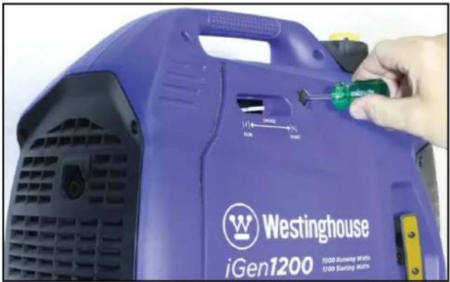
- iGen1200: Remove the engine access cover (see Figure 27).
iGen2200 & 2500: Remove the engine access cover (see Figure 28).
iGen4500s: Remove the oil access cover (see Figure 29).
natural_image
Close-up of a purple iGen1200 washing machine with a hand adjusting its green screwdriver (no visible text or symbols on the device body)Figure 27 - iGen1200 Removing the Engine Access Cover

text_image
Westinghouse iGen2200 1800 Pinning Watts 2200 Starting WattsFigure 28 - iGen2200 & 2500 Removing the Engine Access Cover

text_image
D#en4500S 3700 Running Watts 4500 Starting WattsFigure 29 - iGen4500s Removing the Oil Access Cover
natural_image
Close-up of a white plastic component being cut with an arrow indicating rotation (no text or symbols visible)Figure 30 - Removing the Oil Fill Plug
-
Remove oil fill plug by unscrewing it anticlockwise (see Figure 30).
-
Check oil level:
-
Acceptable Oil Level – Oil surface is at the bottom lip of the oil fill plug opening (see Figure 31).
- Low Oil Level – Oil surface is below the bottom lip of the oil fill plug opening. Add oil as required.
- Too High Oil Level - Oil flows out when the oil fill plug is removed. Allow the excess oil to drain out into a waste oil container.

text_image
SAE 10W-30Figure 31 - Checking Oil Level
Adding Engine Oil
Tools required - iGen1200, 2200 & 2500:
Phillips head screwdriver. iGen4500s: None.
- Always operate or maintain the generator on a flat surface.
- Stop the engine, if running.
- Let engine cool down for several minutes allowing crankcase pressure to equalise.
- Remove the engine access cover or oil access cover (see Figure 27, 28 or 29, as applicable).
- Thoroughly clean around the oil fill plug.
- Remove oil fill plug.
- Select the proper engine oil as described in Engine Oil Specification.
- Using the supplied oil funnel, slowly add engine oil to the engine as shown in Figure 32. Check the oil level periodically to avoid overfilling.
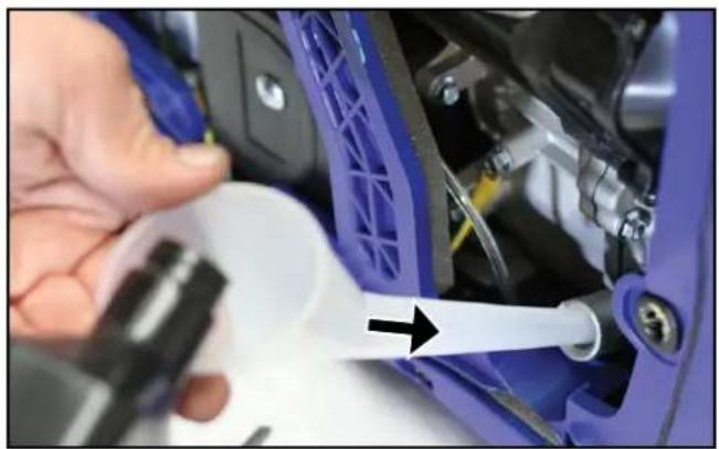
natural_image
Close-up of a hand using a tool to adjust or install a blue automotive component, with no visible text or symbols.Figure 32 - Adding Engine Oil
- Continue to add oil until the oil is at the correct level. See Checking Engine Oil. A simple visual guide is to observe the oil level relative to the bottom lip of the oil filler neck in the engine (into which the oil fill plug is screwed). If the oil reaches the bottom lip, then it's at the high level. If the oil is above the bottom lip and flows out of the hole, then it's too full and the excess must be drained out.
- Reinstall the oil fill plug and engine or oil access cover.
Changing Engine Oil
Tools required - iGen1200, 2200 & 2500:
Phillips head screwdriver and oil drain pan or oil extractor vacuum pump. iGen4500s: Oil drain pan or oil extractor vacuum pump.
- Stop the engine, if running.
- Let engine cool down for several minutes allowing crankcase pressure to equalise.
- Remove the engine access cover or oil access cover (see Figure 27, 28 or 29, as applicable).
- Place oil pan or other suitable container under the oil fill plug.
- With a damp rag, thoroughly clean around the oil fill plug.
- Remove the oil fill plug. Once removed, place the oil fill plug on a clean surface.
natural_image
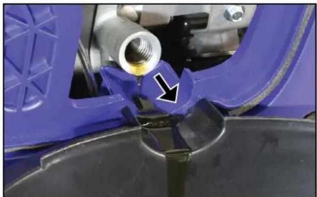
Close-up of a mechanical component with a blue plastic housing and a black base, showing a bolted joint and a white arrow pointing to a specific part (no text or symbols visible)Figure 33 – Draining the Engine Oil
- Tilt the generator over to drain oil into a waste oil pan or container (see Figure 33).
- Allow oil to drain completely.
- Fill crankcase with new oil following the steps outlined in Adding Engine Oil.
- Re-install the oil fill plug and engine or oil access cover.
An alternate and superior method for draining is to use an oil extractor vacuum pump to remove the used oil via the oil fill plug hole.
NOTICE
Never dispose of used engine oil by dumping the oil into a sewer, on the ground, or into groundwater or waterways. Always be environmentally responsible. Follow the guidelines of the government agencies for proper disposal of hazardous materials. Consult local authorities or reclamation facility.
AIR FILTER MAINTENANCE
WARNING

Never use fuel or other flammable solvents to clean the air filter. Use only household detergent and warm water or alternatively a non-flammable solvent.
NOTICE
Do not operate the generator without an air filter element or with a damaged air filter element. This will allow dirt to enter the engine and cause accelerated wear.
Cleaning the Air Filter
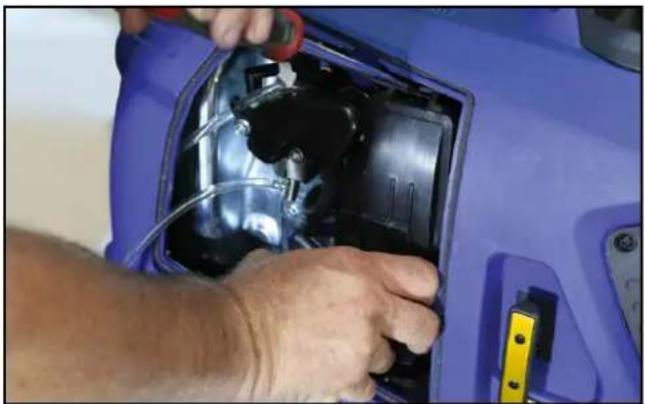
Tools required - iGen1200, 2200 & 2500: Phillips head screwdriver. iGen4500s: Phillips head screwdriver and 10 mm socket wrench.
The air filter must be cleaned after every 50 hours of use or 3 months (frequency should be increased if generator is operated in a dusty environment).
- Turn off the generator and let it cool for several minutes if it's been running.
- Move the generator to a flat, level surface.
- Remove the engine access cover (see Figure 27, 28 or 34, as applicable).
text_image
Westinghouse iGen4500s 3700 Runakatz Veris 4200 Starbuse VerisFigure 34 - iGen4500s Removing the Engine Access Cover
- iGen1200: Remove the air filter cover by pressing down on the locking tab and tipping the cover forwards (see Figure 35). Clean the air filter cover with a rag and place it aside.
iGen2200 & 2500: Remove the air filter cover by undoing the central fixing screw (see Figure 36) to release the cover. Clean the air filter cover with a rag and place it aside.
natural_image
Close-up of hands installing or adjusting a blue car interior panel with visible wiring and components (no text or symbols)Figure 35 - iGen1200 Removing the Air Filter Cover
natural_image
Close-up of a blue and black mechanical device with a hand using a screwdriver to adjust the component (no visible text or symbols)Figure 36 - iGen2200 & 2500 Removing the Air Filter Cover
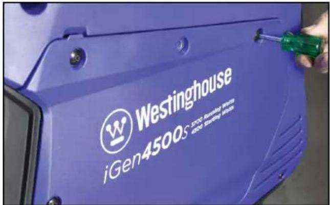
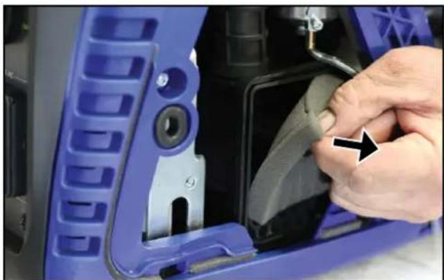
iGen4500s: Remove the air filter cover by turning the twistlocks anti-clockwise and tipping the cover forwards (see Figure 37). Clean the air filter cover with a rag and place it aside.

natural_image
Close-up of a hand pressing down on a blue automotive component with two circular adjustment arrows (no text or symbols visible)Figure 37 - iGen4500s Removing the Air Filter Cover
- Remove the foam air filter element while taking care to note its shape and orientation (see Figure 38). The air filter element must be re-installed later in the same position.
natural_image
Close-up of a hand adjusting a blue plastic car component with a black arrow pointing to the part (no visible text or symbols)Figure 38 - Removing the Air Filter Element
- Wash the air filter element in a solution of household detergent and warm water or alternatively in non-flammable solvent. Slowly squeeze the foam in the liquid for a thorough cleaning action. Then remove the foam and squeeze out the liquid.
NOTICE
NEVER twist or tear the air filter element during cleaning or drying. Apply only a slow and firm squeezing action.
- Rinse the air filter element by immersing it in fresh water and applying a slow squeezing action.
NOTICE
Never dispose of the used cleaning solution or solvent by dumping it into a sewer, on the ground, into groundwater or into a waterway. Always be environmentally responsible. Follow the guidelines of the governmental agencies for proper disposal of hazardous materials. Consult local authorities or reclamation facility.
- Dry the air filter element by repeatedly applying a slow firm squeezing action.
- Coat the air filter element in clean engine oil and then thoroughly squeeze out the excess liquid.
- Re-install the air filter element inside the air filter housing while taking care to ensure that the element is correctly positioned.
- Re-install the air filter and engine access covers.
FUEL STRAINER MAINTENANCE
Check and clean the fuel strainer after every 100 hours of use or 6 months. It is recommended that this maintenance task also be performed each time when filling with fuel from any source other than directly from a service station bowser.
- Stop the generator, if running.
- Allow the generator to cool down until the muffler access cover is cool to the touch.
- Remove the generator to a flat surface.
- Clean area around the fuel cap.
- Turn the fuel cap vent to the ON position, if equipped.
- Remove the fuel cap and set it aside on a clean surface.
- Remove the fuel strainer by hand from inside the filler hole on top of the fuel tank (see Figure 39) taking care not to tear or otherwise damage the fine mesh screen. Keep the fuel strainer vertical so that any trapped liquid or solids do not spill onto the generator.
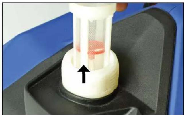
natural_image
Close-up of a mechanical component with a white cylindrical body and red internal structure, mounted on a black base (no visible text or symbols)Figure 39 – Removing the Fuel Strainer
- Pour the contents of the fuel strainer into a suitable waste receptacle. Low pressure compressed air can be used if necessary for blowing onto the outside of the strainer mesh to remove any trapped fine grit.
NOTICE
Never dispose of fuel or fuel contaminants by dumping either of them into a sewer, on the ground, or into groundwater or waterways. Always be environmentally responsible. Follow the guidelines of the government agencies for proper disposal of hazardous materials. Consult local authorities or reclamation facility.
- Re-install the fuel strainer by hand inside the filler hole on top of the fuel tank (see Figure 40). Make sure it is fully inserted into the opening.

natural_image
Close-up of a white ceramic bowl with a red circular component and a black arrow pointing to it, no visible text or symbols.Figure 40 – Re-installing the Fuel Strainer
- Re-install the fuel cap.
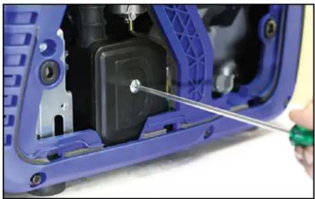
SPARK PLUG MAINTENANCE
Tools required – Phillips head screwdriver (iGen1200 & 4500s), 10 mm socket wrench (iGen4500s), spark plug socket wrench, spark plug gap tool or feeler gauge, and wire brush.
The spark plug should be checked and cleaned after every 100 hours of use or 6 months and then replaced after 250 hours of use or every year.
-
Stop the generator and let it cool for several minutes if it's been running.
-
Move the generator to a flat, level surface.
-
iGen1200: Loosen the locking screw on the spark plug access cover and then slide open and remove the cover (see Figure 41).
iGen2200 & 2500: Slide open and remove the spark plug access cover (see Figure 42).
iGen4500s: Remove the engine access cover (see Figure 34).

natural_image
Close-up of a hand using a tool to mark a blue plastic component (no text or symbols visible)Figure 41 - iGen1200 Removing the Spark Plug Access Cover

natural_image
Close-up of a hand pressing down on a blue car interior (no visible text or symbols)Figure 42 - iGen2200 & 2500 Removing the Spark Plug Access Cover
Table 3: Replacement Spark Plugs
| Spark Plug Make and Model | |||||
| Generator Model Torch Bosch Champion Denso NGK | |||||
| iGen1200 A5RTC - RZ11Y U16FSR-U CR5HSA | |||||
| iGen2200 E6RTC WR7BC+ - W20FPR-U BPR6HS | |||||
| iGen2500 E6RTC WR7BC+ - W20FPR-U BPR6HS | |||||
| iGen4500s | F7RTC | WR5DC+ | RN7Y | W22EPR-U | BPR7ES |
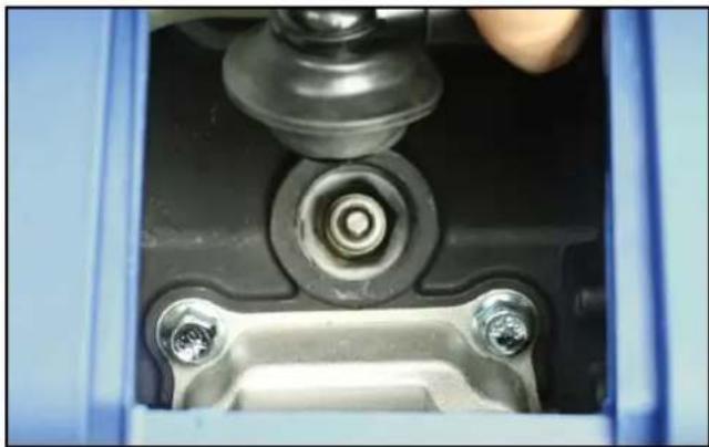
natural_image
Close-up of a mechanical assembly with bolts and a central bolted component (no visible text or symbols)Figure 43 – Removing the Spark Plug Boot
- Remove the spark plug boot by firmly pulling it up and away from the engine (see Figure 43).
NOTICE
Never apply any side load or move the spark plug laterally when removing the spark plug. Applying a side load or moving the spark plug laterally may crack and damage the spark plug insulator.
- Clean area around the spark plug.
- Use a spark plug socket wrench to remove the spark plug from the cylinder head by unscrewing it anti-clockwise (see Figure 44).
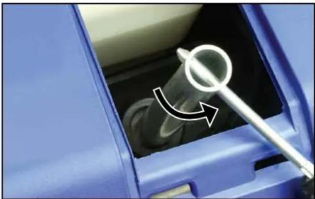
natural_image
Close-up of a blue car interior showing a pipe being inserted, with a white arrow indicating direction (no text or symbols)Figure 44 - Removing the Spark Plug
- Place a clean rag over the opening created by the removal of the spark plug to make sure no dirt can get into the combustion chamber.
-
Inspect the spark plug for:
-
Cracked or chipped insulator; replace the spark plug.
- Excessive wear of the electrodes; replace the spark plug.
- Excessive carbon or oil fouling of the electrodes; clean the electrodes with a wire brush or replace the spark plug.
- Spark plug gap of 0.7 mm or 0.028 inch (see Figure 45); after cleaning with a wire brush, check using a spark plug gap tool or feeler gauge and adjust by carefully bending the ground electrode. Always check the gap of a new spark plug before installing it.
When replacing the spark plug, use only the specified part as listed in Table 3.
NOTICE
Use only the recommended spark plug (Torch brand) or equivalent. The use of a non-recommended spark plug can damage the engine.

text_image
A B G F C D EA - Gap
E - Terminal
B - Ground Electrode
F - Thread
C - Gasket
G - Centre Electrode
D - Insulator
Figure 45 – Spark Plug
- Install the spark plug by following the steps outlined below:
a - Carefully insert the spark plug back into the cylinder head. Hand screw the spark plug clockwise until it bottoms out (seats).
b - Use a spark plug socket wrench to finish tightening the spark plug. If re-installing a used spark plug, tighten approximately 1/8 to 1/4 of a turn after the spark plug seats. If installing a new spark plug, tighten approximately 1/4 to 1/2 a turn after the spark plug seats. The tightening torque should not exceed 12 Nm (9 lb-ft) for the iGen1200 or 17 Nm (13 lb-ft) for the iGen2200, 2500 & 4500s.
c - Replace the spark plug boot, making sure the boot fully engages onto the spark plug's terminal.
- Re-install the spark plug access cover.
SPARK ARRESTER MAINTENANCE
Tools required - iGen2200 & 2500: Phillips head screwdriver and wire brush. iGen4500s: Phillips head screwdriver, 10 mm socket wrench and wire brush.
Check and clean the spark arrester after every 100 hours of use or 6 months.
- Stop the generator and let it cool for several minutes if it's been running.
- Move the generator to a flat, level surface.
- iGen2200 & 2500: Remove the muffler access cover by undoing the six screws affixing it to the generator casing (see Figure 46). Clean the cover and especially its vent holes with a rag or brush and then place it aside.
iGen4500s: Remove the engine access cover (see Figure 34) and then the muffler access cover (see Figure 47). - Loosen the spark arrester band clamp and slide it off the spark arrester collar (see Figure 48).
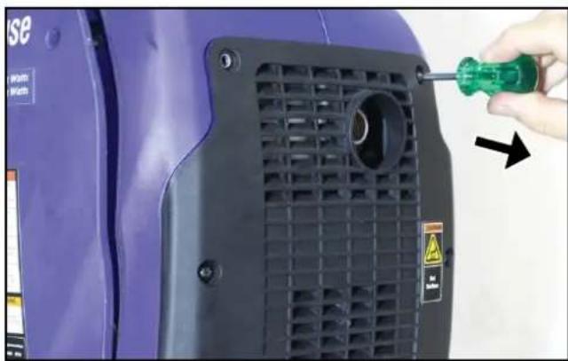
natural_image
Close-up of a purple industrial machine component with a green screwdriver inserted, showing a black grille and mounting holes (no text or symbols visible)Figure 46 – iGen2200 & 2500 Removing the Muffler Access Cover

natural_image
Close-up of a purple industrial machine component with a screwdriver inserted, showing no visible text or symbols.Figure 47 – iGen4500s Removing the Muffler Access Cover
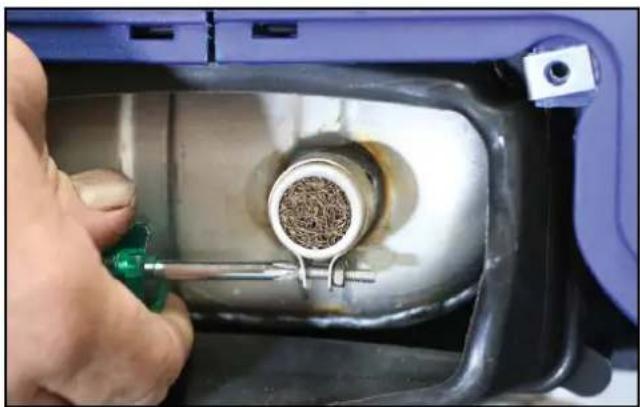
natural_image
Close-up of a hand using a tool to adjust material inside a mechanical device (no visible text or symbols)Figure 48 – Removing the Spark Arrester Band Clamp
- Loosen the locking screw and pull the spark arrester collar and screen off the muffler exhaust pipe (see Figure 49).

natural_image
Close-up of a mechanical component with a metallic cylindrical part inserted into a blue container, being adjusted by a green tool (no visible text or symbols)Figure 49 - Removing the Spark Arrester Collar and Screen
- Use a wire brush to remove any exhaust deposits that may have collected on the spark arrester screen.
- If the spark arrester screen shows signs of wear such as rips, tears or large openings, it should be replaced.
- Re-install the spark arrester components in the following order:
a - Insert the spark arrester screen into its collar and then slide this assembly onto the muffler exhaust pipe. Take care to align one of the slots in the collar with the locking screw. Push the collar on firmly to ensure that the screen is well seated and tighten the locking screw.
b - Place the spark arrester band clamp over the collar with the gap in the band clamp aligned with the collar locking screw. Then tighten the adjusting screw on the band clamp.
- iGen2200 & 2500: Re-install the muffler access cover.
iGen4500s: Re-install the muffler access cover and then the engine access cover.
CLEANING THE GENERATOR
The generator should be kept clean and dry at all times to ensure its reliable and safe operation. This must be checked each time before using the generator.
Use a damp cloth which has been soaked in a mixture of household detergent and warm water and then wrung out to remove excess liquid. Wipe the exterior surfaces of the generator clean and then repeat with a damp cloth which has been rinsed in clean water and wrung out. Finish by wiping off all moisture with a dry cloth. Do not use abrasive or solvent cleaners.
A soft, non-metallic bristle brush or a vacuum cleaner may be used to loosen and remove any built-up dirt, mud or other debris. Low pressure compressed air may also be used to blow off any dirt or dust.
Make sure all of the ventilation grilles are clean of any dirt or other debris otherwise the generator may overheat and be damaged.
NOTICE
NEVER use a water hose or pressure washer to clean the generator. Water may enter the fuel or electric systems and damage the generator. The risk of electric shock is also possible.
12 VOLT BATTERY MAINTENANCE iGen4500s
The generator's 12 Volt battery is a sealed-for-life type that requires no regular maintenance. It is automatically charged whenever the generator is running.
The battery will self-discharge slowly when not in use and after some time it may have insufficient charge to start the generator; in such an event, it may be possible to start the generator manually or otherwise it will be necessary to re-charge or replace the battery.
DANGER

Wet cell batteries produce explosive hydrogen gas while charging. If ignited, the hydrogen gas mixture can explode the battery and cause serious injury or blindness. Only charge a battery in a well-ventilated area away from any sources of ignition such as sparks, open flames, matches, cigarettes, CB radios and mobile phones.

The electrolyte fluid inside a battery contains highly corrosive sulphuric acid, which upon contact with the skin or eyes can cause severe burns or blindness. Always wear protective glasses and clothing – including gloves – when working on a battery. Any electrolyte spill should be thoroughly flushed clean with water.
Charging the Battery
When the generator is not in use, its 12 Volt battery can be charged using a mains-powered 12 Volt battery charger.
Tools required – Flat blade screwdriver, 10 mm spanner and mains-powered 12 Volt battery charger.
- Ensure the generator is stopped and the engine control switch is in the STOP position.
- Allow the generator to cool down if it has been running.
WARNING

NEVER touch both battery terminals simultaneously.
NEVER place a tool or other metal object across both battery terminals. NEVER place a tool or other metal object between either of the battery terminals and any part of the generator.
- Disconnect the two halves of the battery wiring harness connector by pulling them apart from one another.
- Remove the battery from the generator taking care not to touch the battery terminals against the generator's frame or any other metal surface (see Connecting the Battery). Keep the battery upright at all times.
- Disconnect the negative (-) battery cable (black boot) from the negative (-) terminal on the battery.
-
Disconnect the positive (+) battery cable (red boot) from the positive (+) terminal on the battery.
-
Move the battery to a well-ventilated work bench or other suitable location adjacent to the battery charger.
- Charge the battery in accordance with the battery charger's instructions.
- When the battery has finished charging, disconnect it from the battery charger and then re-install it on the generator (see Connecting the Battery).
Replacing the Battery
The procedure for replacing the generator's 12 Volt battery with a new one is essentially the same as that described in the preceding section, except a new battery should be re-installed at Step 9 instead of the old one.
It is recommended to use a genuine replacement battery purchased from an authorised Westinghouse Outdoor Power Equipment dealer or service agent for optimum fit and performance. If this is not possible, an aftermarket battery such as a Motobatt MB5.5U or Yuasa 12N5-3B, 12N5.5-3B or YB5L-B can be substituted albeit with some stretch manipulation of the battery hold-down strap.
REMOTE CONTROL FOB MAINTENANCE
The remote control fob is fitted with a single CR2016 3 Volt lithium coin battery. After extended use, the battery will become discharged and need to be replaced.
To change the battery, use a jeweller's-size Phillips head screwdriver to remove the three screws affixing the back cover of the remote control fob. Carefully remove the old battery – taking care not to damage the printed circuit board or other electronic components inside the remote control – and replace it with a new one. Then replace the back cover and re-install the screws.
It is not usually necessary to pair the remote control fob with the generator anew after replacing the remote control's battery.
DRAINING THE FUEL
Occasionally it may be necessary to drain all of the fuel out of the generator. For example, to remove contaminated or stale fuel or to prepare the generator for transport or storage.
Tools required – Flat blade screwdriver (iGen1200 & 4500s), Phillips head screwdriver (iGen2200 & 2500), fuel siphon hand pump and fuel storage container.
- Turn the fuel cap vent to the ON position (iGen1200, 2200 & 2500).
-
Remove the fuel cap.
-
Clean the fuel strainer (see Fuel Strainer Maintenance), but do not re-install it.
- Pour or siphon the contents of the fuel tank into a fuel storage container (see Figure 50).
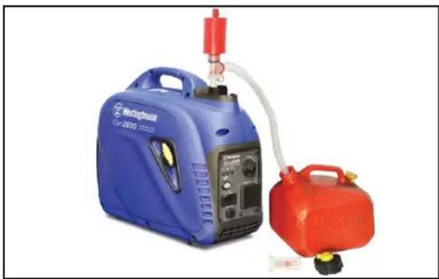
natural_image
Blue and red portable gas generation equipment (no visible text or symbols)Figure 50 – Emptying the Fuel Tank
- Remove the engine access cover (see Figure 27, 28 or 34, as applicable).
- Locate the fuel drain hose connected to the bottom of the carburettor float bowl. Take note of the hose's stowed position routed downwards and then gently pull the loose end of the hose out of the generator casing.
- Position the fuel storage container to collect the remaining fuel discharged from the drain hose.
- Turn the fuel control switch to the ON position.
- Use the screwdriver to loosen the fuel drain screw and then carefully drain the fuel out (see Figure 51, 52 or 53, as applicable). Take care to wipe up any spills immediately.
- When all of the fuel has been drained out, tighten the fuel drain screw. Move the storage container and any fuel soaked rags away from the generator. It is preferable to consume the fuel in another engine-powered device straight away or dispose of it properly rather than storing it for a long time with fuel stabiliser for later re-use.
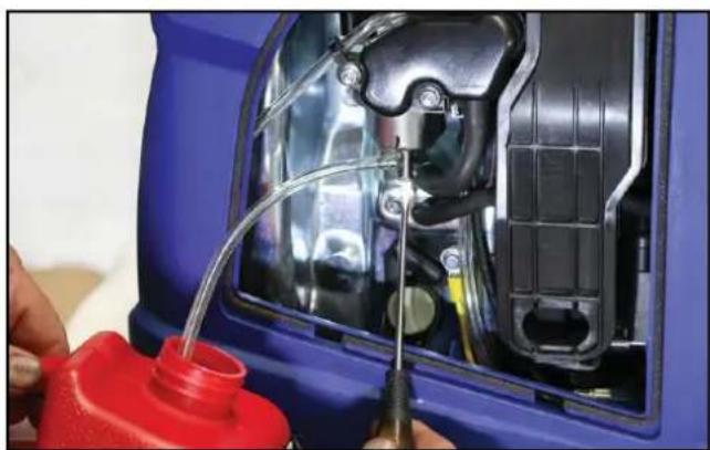
natural_image
Close-up of a blue car hood with internal components and red plastic container being inserted (no visible text or symbols)Figure 51 - iGen1200 Draining the Carburettor
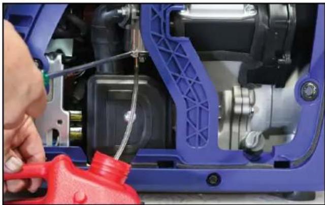
natural_image
Close-up of a blue automotive engine component being adjusted by a red tool, no visible text or symbolsFigure 52 – iGen2200 & 2500 Draining the Carburettor

natural_image
Close-up of hands installing or repairing a blue automotive engine component with red parts (no visible text or symbols)Figure 53 - iGen4500s Draining the Carburettor
NOTICE
Never dispose of fuel or fuel contaminants by dumping either of them into a sewer, on the ground, or into groundwater or waterways. Always be environmentally responsible. Follow the guidelines of the governmental agencies for proper disposal of hazardous materials. Consult local authorities or reclamation facility.
- Turn the fuel control switch to the OFF position.
- Re-stow the fuel drain hose back to its original position routed downwards within the generator casing. Take care to ensure that the hose is correctly routed and not touching any potentially hot components.
- Re-install the engine access cover.
- Re-install the fuel strainer.
- Re-install the fuel cap.
- Turn the fuel cap vent to the OFF position (iGen1200, 2200 & 2500).
LONG-TERM STORAGE
WARNING

Never store a generator with fuel in the tank indoors or in a poorly ventilated area where the fumes can come into contact with an ignition source such as: a pilot light of a stove, water heater, clothes dryer or any other gas appliance; or a spark from an electric appliance.
NOTICE
Fuel stored for as little as 30 days can go bad, causing gum, varnish and corrosive build-up in fuel lines, fuel passages and the engine. This corrosive build-up restricts the flow of fuel, preventing an engine from starting after a prolonged period of storage.
The most commonly experienced faults with portable generators are directly attributable to stale fuel. Such faults are not covered by the generator's warranty.
The generator should be run at least once per month for 30 minutes under no less than one-third load. If this is not possible, the generator should be prepared for long-term storage as described hereunder.
Proper care should be taken to prepare the generator for any long-term storage. This will protect the generator's function and appearance, and will make it easier to start when next required.
Storage Procedure for 1 – 3 Months
- Clean the generator as outlined in Cleaning the Generator.
- Add a proprietary fuel stabiliser to the fuel tank and then add fresh fuel up to the tank's maximum capacity (see Checking and Adding Fuel). Follow the manufacturer's recommendation for correct amount of stabiliser to add.
- Start the generator and run it for 10 minutes to ensure that treated fuel is distributed throughout the engine's fuel system.
- Stop the generator (see Stopping the Generator).
- Turn the fuel control switch to the OFF position if not already done in Step 4.
- Turn the fuel cap vent to the OFF position.
- Allow the unit to cool down and then move it to a clean, dry place for storage.
Storage Procedure for Greater than 3 Months
- Clean the generator as outlined in Cleaning the Generator.
-
Drain the fuel (see Draining the Fuel).
-
Start the generator, if possible, and run the engine without load until it stops when the last remnants of fuel have been used. (See Starting the Generator and Stopping the Generator).
-
Change the engine oil (see Changing Engine Oil).
-
Remove the spark plug (see Spark Plug Maintenance) and pour a tablespoon of clean engine oil into the spark plug opening. While placing a clean rag over the spark plug opening, slowly pull the recoil starter handle to rotate the engine several times. This will distribute the oil and protect the cylinder wall from corrosion during storage.
-
Re-install the spark plug (see Spark Plug Maintenance).
-
Slowly pull the recoil starter handle until resistance is felt, at which point the piston is coming up on its compression stroke and both the intake and exhaust valves are closed. Storing the engine in this position will help to prevent internal corrosion.
-
Move the unit to a clean, dry place for storage.
Removal from Storage
Follow the normal procedures for pre-operation checks and starting (see Before Starting the Generator).
Use only fresh fuel to re-fill the tank, if necessary, rather than re-using any old fuel.
If oil was inserted into the cylinder prior to storage, the exhaust may smoke for a short while after starting the generator; this is normal and will cease within a minute or so of running time.
DISMANTLING AND DISPOSAL
There is no requirement for the generator to be dismantled during normal operation other than for major repair / overhaul or prior to final disposal at the end of its service life.
Dismantling should only be carried out by a mechanically proficient person with access to proper tools or alternatively by your authorised Westinghouse service dealer for a fee.
Before dismantling:
- Stop the generator (see Stopping the Generator).
- Drain the engine oil (see Changing Engine Oil).
- Drain the fuel (see Draining the Fuel).
NOTICE
Do not pollute the environment by improper or illegal disposal of the waste fluids. Dispose of these hazardous items only at an authorised waste collection / recycling facility.
Do not pollute the environment by improper or illegal disposal of the generator either as a whole or in parts. Take the unwanted unit or components to your local recycling centre instead. The generator is made almost entirely of metal that can be recycled.
WARNING

Before attempting to service or troubleshoot the generator, the owner or service technician must first read and understand this instruction manual and comply with all safety instructions. Failure to follow all instructions may result in conditions leading to voiding of the product warranty, serious personal injury, property damage or even death.
| PROBLEM POTENTIAL | CAUSE SOLUTION | |
| Engine will not start or starts and runs rough. | 1. Low oil level. 1. Check oil level and add oil if necessary. | |
| 2. Generator is out of fuel. 2. Check fuel level and add fuel if necessary. | ||
| 3. Fuel is stale or contaminated with water or other foreign substance. | 3. Drain fuel and refill with fresh fuel. | |
| 4. Electrical load connected to generator. | 4. Unplug or switch off any electrical cords or devices from the 240-Volt AC receptacles. | |
| 5. Fuel cap vent is in the OFF position. | 5. Move fuel cap vent to the ON position. | |
| 6. Fuel control switch is in the OFF position. | 6. Move fuel control switch to the ON or CHOKE position. | |
| 7. Engine control switch is in the STOP position (iGen4500s). | 7. Push engine control switch into the AUTO RUN position (iGen4500s). | |
| 8. Engine is not choked (if cold). | 8. Move choke control to the START or CHOKE position. | |
| 9. Engine is over choked (if hot). | 9. Move choke control to either midway between the START and RUN positions or fully to the RUN or ON position. | |
| 10. Spark plug boot is not properly connected onto spark plug terminal. | 10. Push spark plug boot firmly onto spark plug. | |
| 11. Spark plug is dirty or faulty. 11. | Clean or replace spark plug. | |
| 12. Air filter is dirty or blocked. 12. | Check air filter element and clean if necessary. | |
| 13. Spark arrester is dirty or blocked. | 13. Check spark arrester and clean if necessary. | |
| 14. If above possible causes are checked and eliminated, generator may be faulty. | 14. Take generator to an authorised Westinghouse service dealer. | |
| Electric starter will not crank engine fast enough or at all (iGen4500s). | 1. Electrical load connected to generator. | 1. Unplug or switch off any electrical cords or devices from the 240-Volt AC receptacles. |
| 2. Flat battery. 2. Start engine manually, if possible, or recharge battery using an external battery charger. | ||
| 3. Faulty battery. 3. Replace battery. | ||
| 4. Remote control fob is out of range, blocked by interference or not functioning properly. | 4. Move the remote control fob closer to and in direct line of sight of the generator. If unresolved, replace the remote control battery and pair the remote control fob with the generator. | |
| 5. If above possible causes are checked and eliminated, generator may be faulty. | 5. Take generator to an authorised Westinghouse service dealer. | |
| Engine is running, but no 240-Volt AC output is available. | 1. If output indicator light is green, 240-Volt AC output should be available. | 1. Check connected electrical cord(s) or appliance(s) as described below. |
| 2. Connected electrical cord or appliance plug is not properly inserted into 240-Volt AC outlet socket. | 2. Check connected electrical cord or appliance plug is fully inserted into 240-Volt AC outlet socket. | |
| 3. Connected electrical cord or appliance is faulty. | 3. Connect known functioning appliance directly into generator's 240-Volt AC outlet socket to verify electrical output. | |
| 4. If output indicator light is not illuminated, there is no 240-Volt AC output available. In such case:If overload alarm light is not illuminated, generator may be faulty.If overload alarm light is red, there is an overload or short circuit in the connected 240-Volt AC load. | 4.Disconnect all electrical cords and devices from generator and press the generator reset button (iGen4500s only). If unresolved, stop and re-start engine with ECO throttle switch in the OFF position. If still unresolved, take generator to an authorised Westinghouse service dealer.Disconnect all electrical cords and devices from generator and press the generator reset button (iGen4500s only). If unresolved, stop and re-start engine with ECO throttle switch in the OFF position. Reconnect and test run 240-Volt AC loads individually; any single cord or device that trips overload alarm is either faulty or too great a load for the generator. Any faulty device must not be used further until checked and approved by a licensed electrician. Check running and starting power demands of total connected electrical load versus generator's rating. | |
| 5. If above possible causes are checked and eliminated, generator may be faulty. | 5. Take generator to an authorised Westinghouse service dealer. | |
| Engine is running, but no 5 or 12-Volt DC output is available. | 1. Connected electrical cord or appliance plug is not properly inserted into the DC outlet socket. | 1. Check connected electrical cord or appliance plug is fully inserted into the DC outlet socket. |
| 2. Connected electrical cord or appliance is faulty. | 2. Connect known functioning appliance directly into generator's 12-Volt DC outlet socket to verify electrical output. | |
| 3. Overload or short circuit in the connected DC load | 3. Disconnect all electrical cords and devices from generator. Re-start engine with ECO throttle switch in the OFF position. Check that the DC device(s) do not overload the generator's rated DC output(s). Check that the DC device(s) are not faulty, e.g. short circuit. Damage caused to the generator by excessive or faulty DC loads is not covered by warranty. | |
| 4. If above possible causes are checked and eliminated, generator may be faulty. | 4. Take generator to an authorised Westinghouse service dealer. | |
| Engine stops during operation. | 1. Generator is out of fuel. 1. Check fuel level and add fuel if necessary. | |
| 2. Fuel is contaminated with water or other foreign substance. | 2. Drain fuel and refill with fresh fuel. | |
| 3. Fuel cap vent is in the OFF position. | 3. Move fuel cap vent to the ON position. | |
| 4. Fuel control switch is in the OFF position. | 4. Move fuel control switch to the ON position. | |
| 5. Low oil level. 5. Check oil level and add oil if necessary. | ||
| 6. Spark plug boot is not properly connected onto spark plug terminal. | 6. Push spark plug boot firmly onto spark plug. | |
| 7. Overload or short circuit in the connected 240-Volt AC load. | 7. Disconnect all electrical cords and devices from generator. Re-start generator with ECO throttle switch in the OFF position and then re-connect electrical loads individually if possible. If only single load, check running and starting power demands versus generator's AC output rating. | |
| 8. If above possible causes are checked and eliminated, generator may be faulty. | 8. Take generator to an authorised Westinghouse service dealer. | |
| Engine runs erratically or does not hold steady speed. | 1. Power demand of connected 240-Volt AC load may be varying. | 1. Engine speed varies when electrical load changes; this is normal operation. It is most noticeable when ECO throttle switch is in the ON position. No fault. |
| 2. If output indicator and overload alarm are both illuminated, there is an overload in the connected 240-Volt AC load. | 2. Switch off or unplug connected 240-Volt AC device(s) to reduce electrical power demand. | |
| 3. Engine is not warm enough. 3. | Disconnect all electrical cords and appliances from generator. Allow engine to run for at least 2 minutes after the choke control has been moved to the RUN or ON position before reconnecting electrical loads. | |
| 4. Choke control is in the START or CHOKE position and engine is already warm or hot. | 4. Move choke control to the RUN or ON position. | |
| 5. Fuel is stale or contaminated. | 5. Drain fuel and refill with fresh fuel. | |
| 6. Air filter is dirty or blocked. 6. | Check air filter element and clean if necessary. | |
| 7. If above possible causes are checked and eliminated, generator may be faulty. | 7. Take generator to an authorised Westinghouse service dealer. | |
| PARAMETER iGen1200 | iGen2200 iGen2500 | iGen4500s | |||
| ENGINE | Type | 1-Cylinder, 4-Stroke, Overhead Valve, Air Cooled | |||
| Displacement (cm3) 54 79 98 224 | |||||
| Max. Speed (rpm) 5,200 5,300 5,500 3,600 | |||||
| Oil Capacity (mL) 250 350 350 600 | |||||
| Low Oil Shutdown | Yes | Yes | Yes | Yes | |
| Spark Plug | Torch A5RTC | Torch E6RTC | Torch E6RTC | Torch F7RTC | |
| Fuel | Unleaded Petrol | ||||
| Fuel Tank Capacity (L) | 2.8 4.3 4.3 13.5 | ||||
| Fuel Gauge | No | No | No | Yes | |
| Starting Method | Recoil | Recoil | Recoil | Electric | |
| Battery Included | N/A | N/A | N/A | Yes | |
| 240 V AC ELECTRICAL | Voltage (V) | 240 | 240 | 240 | 240 |
| Frequency (Hz) | 50 | 50 | 50 | 50 | |
| No. of Phases | 1 | 1 | 1 | 1 | |
| Continuous Running Power (W)* | 1,000 | 1,800 | 2,200 | 3,700 | |
| Maximum Starting Power (W) | 1,200 | 2,200 | 2,500 | 4,500 | |
| Continuous Running Current (A) | 4.2 | 7.5 | 9.2 | 15.4 | |
| Voltage & Waveform Control | Digital Inverter, Pure Sine Wave Output | ||||
| Receptacle(s) | 1 x 15 A, IP44 | 1 x 15 A, IP44 | 1 x 15 A, IP44 | 2 x 15 A, IP44 | |
| Overload Protection | Electronic | ||||
| Alternator | Brushless, Permanent Magnet | ||||
| Output Power Meter | No | No | No | Yes | |
| 12 V DC ELECTRICAL | Voltage (V) | 12 | N/A | N/A | 12 |
| Maximum Current (A) | 5 | N/A | N/A | 8 | |
| Maximum Power (W) | 60 | N/A | N/A | 100 | |
| Receptacle | 1 x 5 A, IP44 | N/A | N/A | 1 x 8 A, IP44 | |
| 5 V DC ELECTRICAL | Voltage (V) | 5 | 5 | 5 | 5 |
| Maximum Current (A) | 2.1 2.1 2.1 2.1 | ||||
| Maximum Power (W) | 10 10 10 10 | ||||
| Receptacle | USB Type A, IP44 | ||||
| DIMENSIONS & WEIGHT | Length (mm) | 463 500 500 650 | |||
| Width (mm) | 262 285 285 480 | ||||
| Height (mm) | 395 450 450 520 | ||||
| Weight - Dry (kg) | 15 | 21 | 21.5 | 49.5 | |
| Weight - Wet (kg) | 17 | 24.5 | 25 | 60 | |
* Rated output at 1.0 power factor.
iGen1200 WIRING DIAGRAM

flowchart
graph TD
    A["DC Coil"] --> B["Bu"]
    B --> C["Bu"]
    C --> D["DC Rectifier"]
    D --> E["R"]
    E --> F["BI"]
    F --> G["5V DC USB Socket"]
    G --> H["12V DC Accessory Socket"]
    I["Sub Coil"] --> J["W"]
    J --> K["BI"]
    K --> L["Inverter"]
    L --> M["R"]
    M --> N["W"]
    N --> O["AC Socket"]
    P["Main Coil"] --> Q["Bl"]
    Q --> R["BI"]
    R --> S["Stepping Motor"]
    S --> T["Engine Switch"]
    T --> U["Ignition Device"]
    U --> V["Low Oil Indicator Light"]
    W["Ignition Coil"] --> X["Y/G"]
    X --> Y["R"]
    Y --> Z["Spark Plug"]
    Z --> AA["Oil Level Sensor"]
    AB["Trigger"] --> AC["M"]
    AC --> AD["Br"]
    AD --> AE["Br/R"]
    AE --> AF["Output Indicator Light"]
    AG["Overload Indicator Light"] --> AH["Efficiency Switch"]
    AI["Light"] --> AJ["Blue/Red/White/Black/Red"]
iGen2200 & 2500 WIRING DIAGRAM
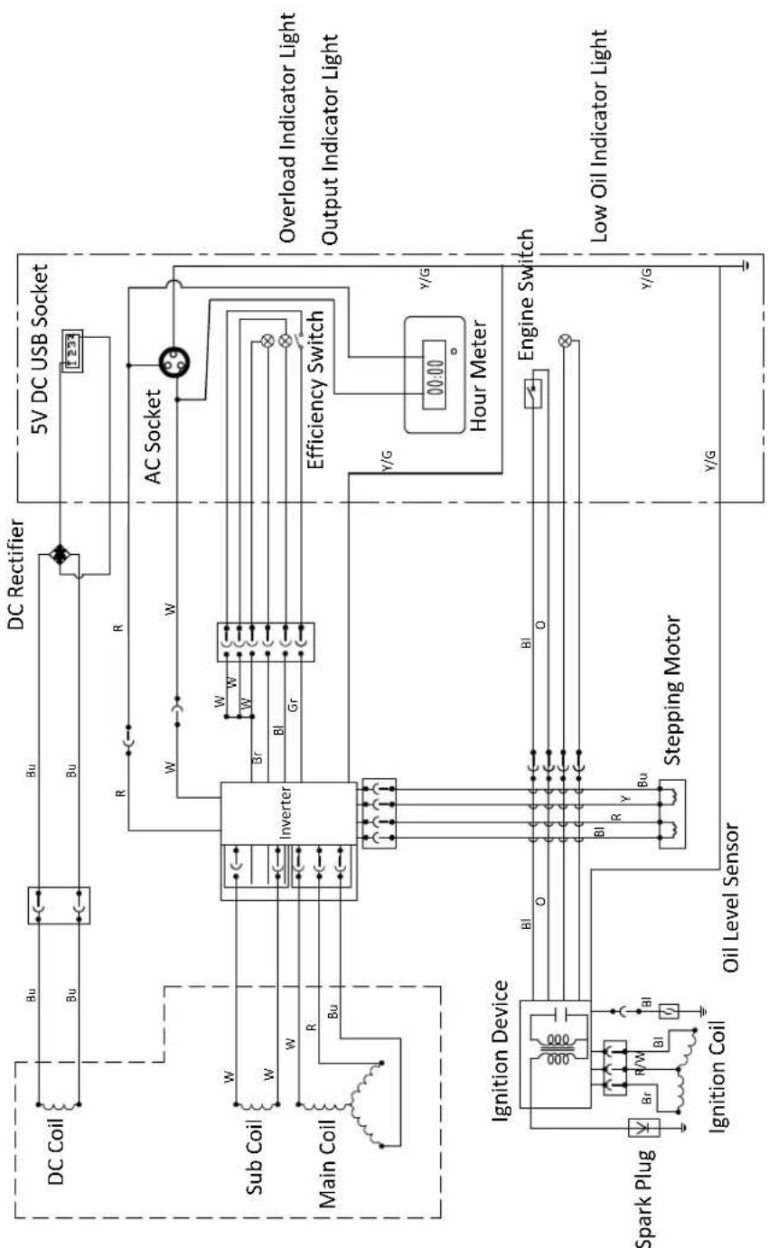
flowchart
graph TD
    subgraph Main Coil
        A["DC Coil"] --> B["Inverter"]
        C["Sub Coil"] --> B
        D["Main Coil"] --> B
        B --> E["Stepping Motor"]
        E --> F["Oil Level Sensor"]
        G["Ignition Device"] --> H["Br, R/W, BI, Bu"]
        I["Spark Plug"] --> J["Ignition Coil"]
    end

    subgraph Inverter
        K["DC Rectifier"] --> L["5V DC USB Socket"]
        M["AC Socket"] --> N["Efficiency Switch"]
        O["Hour Meter"] --> P["Y/G"]
        Q["Engine Switch"] --> R["Y/G"]
        S["Low Oil Indicator Light"] --> T["Y/G"]
    end

    subgraph Inverter
        U["W"] --> V["Br"]
        W["W"] --> X["BI"]
        Y["Gr"] --> Z["AC"]
    end

    subgraph Inverter
        AA["W"] --> AB["Br"]
        AC["W"] --> AD["BI"]
        AE["Gr"] --> AF["AC"]
    end

    subgraph Inverter
        AG["R"] --> AH["Steving Motor"]
        AI["R"] --> AJ["Stepping Motor"]
    end

    subgraph Inverter
        AK["R"] --> AL["Steving Motor"]
        AM["R"] --> AN["Stepping Motor"]
    end

    subgraph Inverter
        AO["W"] --> AP["Steving Motor"]
        AQ["W"] --> AR["Stepping Motor"]
    end

    subgraph Inverter
        AS["W"] --> AT["Steving Motor"]
        AU["W"] --> AV["Stepping Motor"]
    end

    subgraph Inverter
        AW["W"] --> AX["Steving Motor"]
        AY["W"] --> AZ["Stepping Motor"]
    end

    subgraph Inverter
        BA["W"] --> BB["Steving Motor"]
        BC["W"] --> BD["Stepping Motor"]
    end

    subgraph Inverter
        BE["BI"] --> BF["Steving Motor"]
        BG["BI"] --> BH["Stepping Motor"]
    end

    subgraph Inverter
        BI["BI"] --> BJ["Steving Motor"]
        BK["Bu"] --> BL["Stepping Motor"]
    end

    subgraph Inverter
        BM["BI"] --> BN["Steving Motor"]
        BO["Bu"] --> BP["Stepping Motor"]
    end

    subgraph Inverter
        BQ["W"] --> BR["Steving Motor"]
        BS["W"] --> BT["Stepping Motor"]
    end

    subgraph Inverter
        BU["W"] --> BV["Steving Motor"]
        BW["W"] --> BX["Stepping Motor"]
    end

    subgraph Inverter
        BY["W"] --> BZ["Steving Motor"]
        BYX["W"] --> BYZ["Stepping Motor"]
    end

    subgraph Inverter
        BZ --> CA["Steving Motor"]
        BZ --> CB["Stepping Motor"]
    end

    subgraph Inverter
        CC["W"] --> CD["Steving Motor"]
        CC --> CE["Stepping Motor"]
    end

    subgraph Inverter
        DD["W"] --> DDZ["Steving Motor"]
        DD --> DDZ
        DD --> DDZ
        DD --> DDZ
    end

    subgraph Inverter
        DDZ --> DF["Steving Motor"]
        DDZ --> DG["Stepping Motor"]
    end

    subgraph Inverter
        DF --> DH["Steving Motor"]
        DF --> DI["Stepping Motor"]
    end

    subgraph Inverter
        DH --> DJ["Steving Motor"]
        DH --> DK["Stepping Motor"]
    end

    subgraph Inverter
        DJ --> DL["Steving Motor"]
        DJ --> DV["Stepping Motor"]
    end

    subgraph Inverter
        DL --> DW["Steving Motor"]
        DL --> DWZ["Stepping Motor"]
    end

    subgraph Inverter
        DWZ --> DX["Steving Motor"]
        DWZ --> DXZ["Stepping Motor"]

    subgraph Inverter
        DXZ --> DXZ1["Y/G"]

    subgraph Inverter
        DXZ1 --> DXZ2["Y/G"]

    subgraph Inverter
        DXZ2 --> DXZ3["Y/G"]

    subgraph Inverter
        DXZ3 --> DXZ4["Y/G"]

    subgraph Inverter
        DXZ4 --> DXZ5["Y/G"]

    subgraph Inverter
        DXZ5 --> DXZ6["Y/G"]

    subgraph Inverter
        DXZ6 --> DXZ7["Y/G"]

    subgraph Inverter
        DXZ7 --> DXZ8["Y/G"]

    subgraph Inverter
        DXZ8 --> DXZ9["Y/G"]

    subgraph Inverter
        DXZ9 --> DXZ10["Y/G"]

    subgraph Inverter
        DXZ10 --> DXZ11["Y/G"]

    subgraph Inverter
        DXZ11 --> DXZ12["Y/G"]

    subgraph Inverter
        DXZ12 --> DXZ13["Y/G"]

    subgraph Inverter
        DXZ13 --> DXZ14["Y/G"]

    subgraph Inverter
        DXZ14 --> DXZ15["Y/G"]

    subgraph Inverter
        DXZ15 --> DXZ16["Y/G"]

    subgraph Inverter
        DXZ16 --> DXZ17["Y/G"]

    subgraph Inverter
        DXZ17 --> DXZ18["Y/G"]

    subgraph Inverter
        DXZ18 --> DXZ19["Y/G"]

    subgraph Inverter
        DXZ19 --> DXZ20["Y/G"]

    subgraph Inverter
        DXZ20 --> DXZ21["Y/G"]

    subgraph Inverter
        DXZ21 --> DXZ22["Y/G"]

    subgraph Inverter
        DXZ22 --> DXZ23["Y/G"]

    subgraph Inverter
        DXZ23 --> DXZ24["Y/G"]

    subgraph Inverter
        DXZ24 --> DXZ25["Y/G"]

    subgraph Inverter
        DXZ25 --> DXZ26["Y/G"]

    subgraph Inverter
        DXZ26 --> DXZ27["Y/G"]

    subgraph Inverter
        DXZ27 --> DXZ28["Y/G"]

    subgraph Inverter
        DXZ28 --> DXZ29["Y/G"]

    subgraph Inverter
        DXZ29 --> DXZ30["Y/G"]

    subgraph Inverter
        DXZ30 --> DXZ31["Y/G"]

    subgraph Inverter
        DXZ31 --> DXZ32["Y/G"]

    subgraph Inverter
        DXZ32 --> DXZ33["Y/G"]

    subgraph Inverter
        DXZ33 --> DXZ34["Y/G"]

    subgraph Inverter
        DXZ34 --> DXZ35["Y/G"]

    subgraph Inverter
        DXZ35 --> DXZ36["Y/G"]

    subgraph Inverter
        DXZ36 --> DXZ37["Y/G"]

    subgraph Inverter
        DXZ37 --> DXZ38["Y/G"]

    subgraph Inverter
        DXZ38 --> DXZ39["Y/G"]

    subgraph Inverter
        DXZ39 --> DXZ40["Y/G"]

    subgraph Inverter
        DXZ40 --> DXZ41["Y/G"]

    subgraph Inverter
        DXZ41 --> DXZ42["Y/G"]

    subgraph Inverter
        DXZ42 --> DXZ43["Y/G"]

    subgraph Inverter
        DXZ43 --> DXZ44["Y/G"]

    subgraph Inverter
        DXZ44 --> DXZ45["Y/G"]

    subgraph Inverter
        DXZ45 --> DXZ46["Y/G"]

    subgraph Inverter
        DXZ46 --> DXZ47["Y/G"]

    subgraph Inverter
        DXZ47 --> DXZ48["Y/G"]

    subgraph Inverter
        DXZ48 --> DXZ49["Y/G"]

    subgraph Inverter
        DXZ49 --> DXZ50["Y/G"]

    subgraph Inverter
        DXZ50 --> DXZ51["Y/G"]

    subgraph Inverter
        DXZ51 --> DXZ52["Y/G"]

    subgraph Inverter
        DXZ52 --> DXZ53["Y/G"]

    subgraph Inverter
        DXZ53 --> DXZ54["Y/G"]

    subgraph Inverter
        DXZ54 --> DXZ55["Y/G"]

    subgraph Inverter
        DXZ55 --> DXZ56["Y/G"]

    subgraph Inverter
        DXZ56 --> DXZ57["Y/G"]

    subgraph Inverter
        DXZ57 --> DXZ58["Y/G"]

    subgraph Inverter
        DXZ58 --> DXZ59["Y/G"]

    subgraph Inverter
        DXZ59 --> DXZ60["Y/G"]

    subgraph Inverter
        DXZ60 --> DXZ61["Y/G"]

    subgraph Inverter
        DXZ61 --> DXZ62["Y/G"]

    subgraph Inverter
        DXZ62 --> DXZ63["Y/G"]

    subgraph Inverter
        DXZ63 --> DXZ64["Y/G"]

    subgraph Inverter
        DXZ64 --> DXZ65["Y/G"]

    subgraph Inverter
        DXZ65 --> DXZ66["Y/G"]

    subgraph Inverter
        DXZ66 --> DXZ67["Y/G"]

    subgraph Inverter
        DXZ67 --> DXZ68["Y/G"]

    subgraph Inverter
        DXZ68 --> DXZ69["Y/G"]

    subgraph Inverter
        DXZ69 --> DXZ70["Y/G"]

    subgraph Inverter
        DXZ70 --> DXZ71["Y/G"]

    subgraph Inverter
        DXZ71 --> DXZ72["Y/G"]

    subgraph Inverter
        DXZ72 --> DXZ73["Y/G"]

    subgraph Inverter
        DXZ73 --> DXZ74["Y/G"]

    subgraph Inverter
        DXZ74 --> DXZ75["Y/G"]

    subgraph Inverter
        DXZ75 --> DXZ76["Y/G"]

    subgraph Inverter
        DXZ76 --> DXZ77["Y/G"]

    end
Bl Black W White R/W Red/White
Bu Blue Y Yellow Y/G Yellow/Green
Gr Green O Orange
R Red
Br Brown
iGen4500s WIRING DIAGRAM
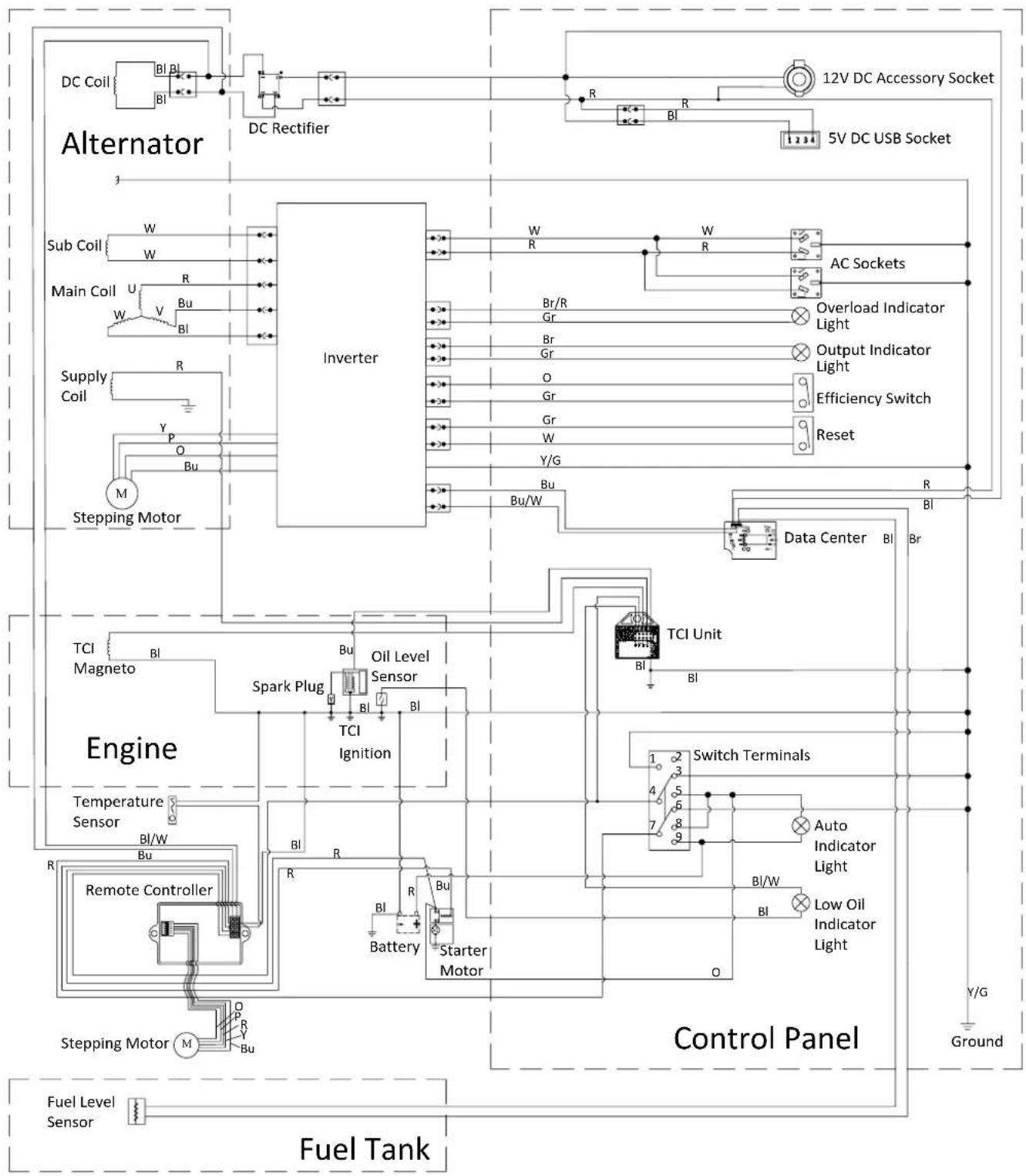
flowchart
graph TD
    subgraph Fuel Tank
        A["Fuel Level Sensor"] --> B["Stepping Motor M"]
        B --> C["Remote Controller R"]
        C --> D["Engine"]
        D --> E["Temperature Sensor BI/W"]
        E --> F["Spark Plug BI"]
        F --> G["Oil Level Sensor BI"]
        G --> H["Inverter"]
        H --> I["DC Rectifier"]
        I --> J["DC Coil BI BL BI"]
        J --> K["Alternator"]
        K --> L["Sub Coil W W"]
        L --> M["Main Coil U V Bu BI"]
        M --> N["Supply Coil R Y P O Bu"]
        N --> O["Stepping Motor M"]
    end

    subgraph Control Panel
        P["Control Terminals"] --> Q["Auto Indicator Light BI/W"]
        Q --> R["Low Oil Indicator Light BI"]
        R --> S["Switch Terminals"]
        S --> T["TCI Unit BI"]
        T --> U["Data Center BI Br"]
        U --> V["Reset Reset"]
        V --> W["Efficiency Switch"]
        W --> X["Output Indicator Light"]
        X --> Y["Overload Indicator Light"]
        Y --> Z["AC Sockets"]
        Z --> AA["5V DC USB Socket"]
        AA --> AB["12V DC Accessory Socket"]
    end

    subgraph Inverter
        AC["Inverter"] --> AD["W R"]
        AD --> AE["W R"]
        AE --> AF["AC Sockets"]
        AF --> AG["Overload Indicator Light"]
        AG --> AH["Output Indicator Light"]
        AH --> AI["Efficiency Switch"]
        AI --> AJ["Reset Reset"]
        AJ --> AK["Data Center BI Br"]
    end

    subgraph Control Panel
        AL["Control Panel"] --> AM["Ground Y/G"]
    end
| Bl | Black | Br | Brown | Y/G | Yellow/Green |
| R | Red | Br/R | Brown/Red | Bu/W | Blue/White |
| Bu | Blue | Gr | Grey | Y | Yellow |
| W | White | P | Pink | O | Orange |
| Y | Yellow | Bl/W | Black/White |
WARRANTY AGAINST DEFECTS
Proof of Purchase
It is recommended that you keep a copy of the original tax invoice for your records.
Warrantor
Name: Westinghouse Outdoor Power Equipment (ABN 21101370085)
Address: 21 Resource Street, Parkinson, 4115, Australia
Phone: (1800) 453 626
Email: info@wpowereq.com.au
Web: westinghouseoutdoorpower.com.au
Warranty Conditions
Westinghouse Outdoor Power Equipment (the "Company") warrants that its Westinghouse portable electric generators (the "Goods") shall be free from defects in material and workmanship for a period of two years (2) years or five hundred (500) operating hours, whichever occurs first, from the date of original sale (hereinafter the "Warranty Period") in normal domestic applications such as personal, residential household or recreational use.
A Warranty Period of one (1) year or five hundred (500) operating hours, whichever occurs first, shall apply in commercial applications such as income producing, rental or other business-related use. Goods sold to a Consumer with an Australian Business Number shall be deemed as being used in a commercial application.
The Warranty Period is continuous from the date of original sale and does not restart upon the repair or replacement of the Goods or any part thereof.
Upon return – transportation charges prepaid by the Consumer – to the Company's or its nominated dealer's premises within the Warranty Period, the Company shall repair or replace, at its option, any Goods which it determines to contain defective material or workmanship, and shall return said Goods to the Consumer free-on-board (FOB) at the Company's or agent's premises. The repair or replacement work will be scheduled and performed according to the Company's normal work flow and availability of replacement parts.
The Company shall not be obligated, however, to repair or replace Goods which have been: repaired by others; abused; improperly installed, operated, maintained, repaired, transported or stored; not serviced to schedule using genuine spare parts; altered or otherwise misused or damaged in any way.
The Company shall not be responsible for any diagnosis, communication, dismantling, packing, handling, freight, and reassembly or reinstallation charges.
Freight damage, pre-delivery service, normal operating adjustments, preventative maintenance service, consumable items, cosmetic damage, corrosion, erosion, normal wear and tear, performance, merchantability, and fitness for a particular purpose are not covered under this Warranty. Consumable items include batteries, filters, fuel, lubricants and spark plugs.
The Company shall not be liable for any repairs, replacements, or adjustments to the Goods or any costs of labour performed by the Consumer or others without the Company's prior written approval.
To the extent permissible by law and notwithstanding any other clause in these Warranty Conditions, the Company excludes all liability whatsoever to the Consumer arising out of or in any way connected with a contract for any consequential or indirect losses of any kind howsoever arising and whether caused by breach of statute, breach of contract, negligence or other tort.
The Company's liability will be limited to, in the case of products, the replacement of the products, the supply of equivalent products or the payment of the cost of replacing the products or of acquiring equivalent products or, in the case of services, the supply of the services again or the payment of the cost of having the services supplied again. The choice of remedy will be at the discretion of the Company and the Consumer acknowledges that this limitation of liability is fair and reasonable.
This Warranty is available only to the original Consumer bearing the original tax invoice from the Company or one of its authorised dealers as proof of purchase. Goods purchased from any other party such as a private seller, auction house, eBay seller, etc. are not covered by this Warranty.
Our Goods come with guarantees that cannot be excluded under the Australian Consumer Law. You are entitled to a replacement or refund for a major failure and compensation for any other reasonably foreseeable loss or damage. You are also entitled to have the Goods repaired or replaced if the Goods fail to be of acceptable quality and the failure does not amount to a major failure.

natural_image
Blue circular icon with a white crown and three dots, no text or symbols present.Westinghouse
INNOVATION YOU CAN BE SURE OF
Westinghouse Outdoor Power Equipment
21 Resource Street
Parkinson QLD 4115 Australia
www.westinghouseoutdoorpower.com.au
© 2019 All rights reserved. Content may change without notice.
W, Westinghouse, and INNOVATION YOU CAN BE SURE OF
are trademarks of the Westinghouse Electric Corporation used
under license by Westinghouse Outdoor Power Equipment, LLC.
All rights reserved.