WES31-9200 - Heating WESTINGHOUSE - Free user manual and instructions
Find the device manual for free WES31-9200 WESTINGHOUSE in PDF.

User questions about WES31-9200 WESTINGHOUSE
0 question about this device. Answer the ones you know or ask your own.
Ask a new question about this device
Download the instructions for your Heating in PDF format for free! Find your manual WES31-9200 - WESTINGHOUSE and take your electronic device back in hand. On this page are published all the documents necessary for the use of your device. WES31-9200 by WESTINGHOUSE.
USER MANUAL WES31-9200 WESTINGHOUSE
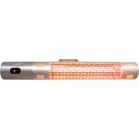
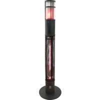
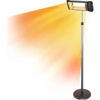
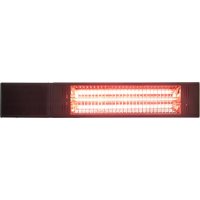
Outdoor Patio Heater
natural_image
Line drawing of a tall outdoor heating tower with vertical panel structure (no text or symbols)Owner's Manual
Carefully and thoroughly read this Owner's Manual before using/operating the sauna.
- Shut off gas to the appliance.
- Extinguish any open flame.
- If odor continues, keep away from the appliance and immediately call your gas supplier or fire department.

WARNING
Do not store or use gasoline or other flammable vapors and liquids in the vicinity of this or any other appliance. A propane cylinder not connected for use shall not be stored in the vicinity of this or any other appliance.

WARNING: For Outdoor Use Only

DANGER
CARBON MONOXIDE HAZARD
This appliance can produce carbon monoxide which has no odor.
Using it in an enclosed space can kill you.
Never use this appliance in an enclosed space such as a camper, tent, car or home.

WARNING
Improper installation, adjustment, alteration, service or maintenance can cause property damage, injury or death. Read the installation, operation and maintenance instructions thoroughly before installing or servicing this equipment.


US
CSA/ANSI Z83.26 :20 • CSA 2.37:20: Gas-fired outdoor infrared patio heaters
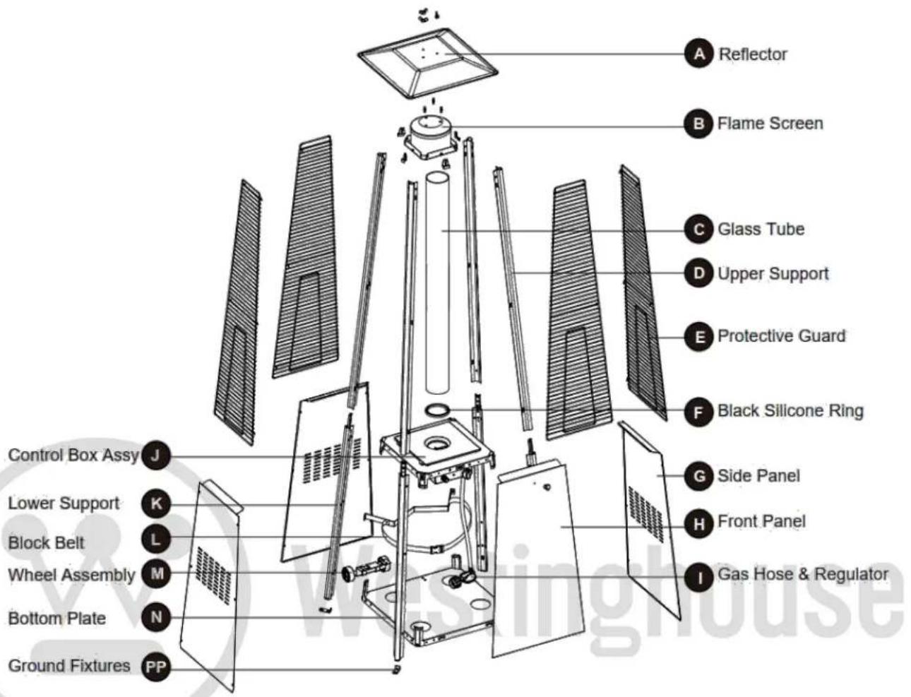
PACKAGE CONTENTS
text_image
A Reflector B Flame Screen C Glass Tube D Upper Support E Protective Guard F Black Silicone Ring G Side Panel H Front Panel I Gas Hose & Regulator Control Box Assy J Lower Support K Block Belt L Wheel Assembly M Bottom Plate N Ground Fixtures PP| PART | DESCRIPTION | QUANTITY |
| A | Reflector | 1 |
| B | Flame Screen | 1 |
| C | Glass Tube | 1 |
| D | Upper Support | 4 |
| E | Protective Guard | 4 |
| F | Black Silicone Ring | 1 |
| G | Side Panel | 3 |
| H | Front Panel | 1 |
| I | Gas Hose & Regulator | 1 |
| J | Control Box Assy | 1 |
| K | Lower Support | 4 |
| PART | DESCRIPTION | QUANTITY |
| L | Block Belt | 1 |
| M | Wheel Assembly | 1 |
| N | Bottom Plate | 1 |
| PP | Ground Fixtures | 4 |
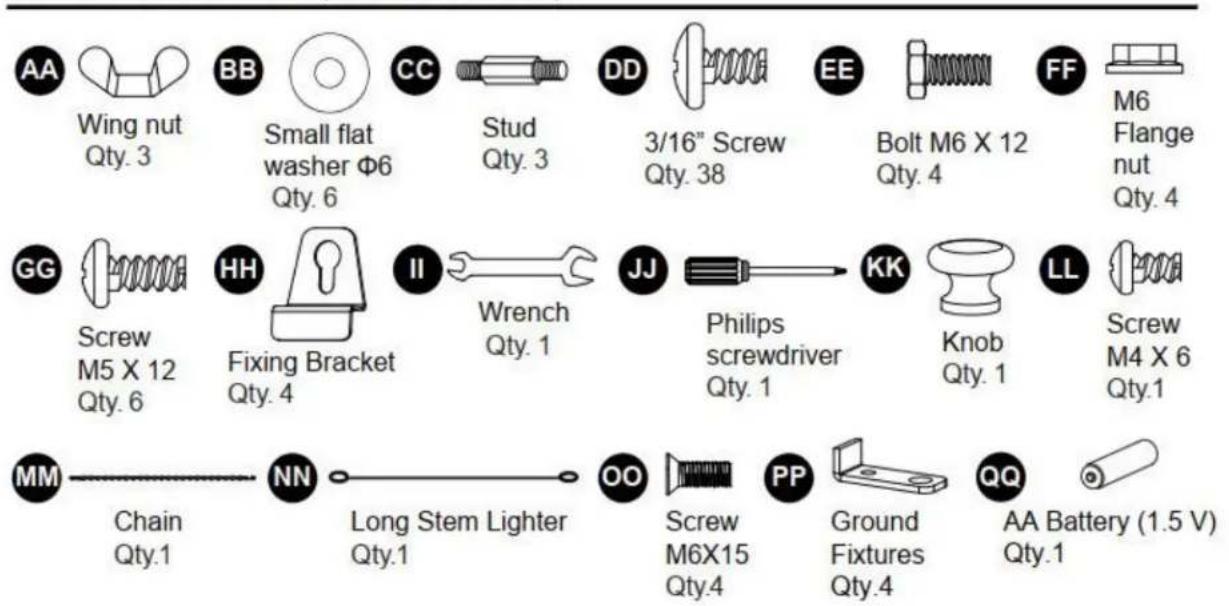
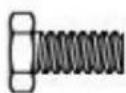
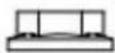
HARDWARE CONTENTS (shown actual size)
text_image
AA Wing nut Qty. 3 BB Small flat washer Φ6 Qty. 6 CC Stud Qty. 3 DD 3/16" Screw Qty. 38 EE Bolt M6 X 12 Qty. 4 FF M6 Flange nut Qty. 4 GG Screw M5 X 12 Qty. 6 HH Fixing Bracket Qty. 4 II Wrench Qty. 1 JJ Philips screwdriver Qty. 1 KK Knob Qty. 1 LL Screw M4 X 6 Qty.1 MM Chain Qty.1 NN Long Stem Lighter Qty.1 OO Screw M6X15 Qty.4 PP Ground Fixtures Qty.4 QQ AA Battery (1.5 V) Qty.1IMPORTANT SAFEGUARDS
Please read and understand this entire manual before attempting to assemble, operate or install the product.
This manual contains important information about the assembly, operation and maintenance of this patio heater. General safety information is presented in these first few pages and is also located throughout the manual. Keep this manual for future reference and to educate new users of this product. This manual should be read in conjunction with the labeling on the product. Safety precautions are essential when any mechanical or propane fueled equipment is involved. These precautions are necessary when using, storing, and servicing. Using this equipment with the respect and caution demanded will reduce the possibilities of personal injury or property damage. The following symbols shown below are used extensively throughout this manual. Always heed these precautions, as they are essential when using any mechanical or fueled equipment. Installation of this appliance at altitudes above 2000 ft (610 m) shall be in accordance with local codes, or in the absence of local codes, ANSI Z223.1/NFPA 54 or CSA B149.1
Do not operate after the appliance malfunctions or has been damaged in any manner. Call customer service: 1-833-895-7333.
The use of accessory attachments is not recommended as they may cause injuries.
! DANGER
DANGER indicates an imminently hazardous situation which, if not avoided, will result in death or serious injury.
! DANGER
Failure to comply with the precautions and instructions provided with this heater can result in death, serious bodily injury and property loss or damage from hazards of fire, explosion, burn, asphyxiation, and/or carbon monoxide poisoning. Only persons who can understand and follow the instructions should use or service this heater.
! DANGER
If you smell gas:
- Shut off gas to the appliance.
- Extinguish any open flame.
- If odor continues, keep away from the appliance and immediately call your gas supplier or fire department
! DANGER
EXPLOSION - FIRE HAZARD
- Keep solid combustibles, such as building materials, paper or cardboard, a safe distance away from the heater as recommended by the instructions.
- Provide adequate clearances around air openings into the combustion chamber.
- Never use the heater in spaces which do or may contain volatile or airborne combustibles, or products such as gasoline, solvents, paint thinner, dust particles or unknown chemicals.
- During operation, this product can be a source of ignition. Keep heater area clear and free from combustible materials, gasoline, paint thinner, cleaning solvents and other flammable vapors and liquids. Do not use this heater in areas with high dust content. Minimum heater clearances from combustible materials: three (3) feet from the sides & three (3) feet from the top.
! DANGER
CARBON MONOXIDE HAZARD
- This heater is a combustion appliance. All combustion appliances produce carbon monoxide (CO) during the combustion process. This product is designed to produce extremely minute, non-hazardous amounts of CO if used and maintained in accordance with all warnings and instructions. Do not block air flow into or out of the heater.
- Carbon Monoxide (CO) poisoning produces flu-like symptoms, watery eyes, headaches, dizziness, fatigue and possibly death. You can't see it and you can't smell it. It's an invisible killer. If these symptoms are present during operation of this product get fresh air immediately!
- For outdoor use only.
- Never use inside a house, or other unventilated or enclosed areas.
- This heater consumes air (oxygen). Do not use it in unventilated or enclosed areas to avoid endangering your life.
! DANGER
EXPLOSION - FIRE HAZARD
- Never store propane near high heat, open flames, pilot lights, direct sunlight, other ignition sources or where temperatures exceed 120 degrees F (49°C).
• Propane vapors are heavier than air and can accumulate in low places. If you smell gas, leave the area immediately. - Never install or remove propane cylinder while heater is lighted, near flame, pilot lights, other ignition sources or while heater is hot to touch.
- This heater is red hot during use and can ignite flammables too close to the burner. Keep flammables at least 3 feet from sides & 3 feet from top. Keep gasoline and other flammable liquids and vapors well away from heater.
- Store the propane cylinder outdoors in a well-ventilated space out of reach of children. Never store the propane cylinder in an enclosed area (house, garage, etc.). If heater is to be stored indoors, disconnect the propane cylinder for outdoor storage.

WARNING
We cannot foresee every use which may be made of our heaters.
Check with your local fire safety authority if you have questions about heater use.
Other standards govern the use of fuel gases and heat producing products for specific uses. Your local authorities can advise you about this.
If no local codes exist, follow National Fuel Gas Code, ANS Z223.1. In Canada, installation must conform to local codes. If no local codes exist, follow the current National standards of CANADA CAN/CGA-B 149.2.

WARNING
WARNING indicates an imminently hazardous situation which, if not avoided, will result in death or serious injury.

WARNING
Do not store or use gasoline or other flammable vapors and liquids in the vicinity of this or any other appliance.
A propane cylinder not connected for use shall not be stored in the vicinity of this or any other appliance.

DANGER
text_image
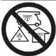
Prohibition sign with pictograms and warning symbols, indicating no liability or insecurityCARBON MONOXIDE HAZARD
This appliance can produce carbon monoxide which has no odor.
Using it in an enclosed space can kill you. Never use this appliance in an enclosed space such as a camper, tent, car or home.

WARNING
Improper installation, adjustment, alteration, service or maintenance can cause property damage, injury or death. Read the installation, operation and maintenance instructions thoroughly before installing or servicing this equipment.

WARNING
California Proposition 65
Combustion by-products produced when using this product contain chemicals known to the State of California to cause cancer, birth defects, and other reproductive harm.

WARNING
BURN HAZARD
- Never leave heater unattended when hot or in use.
- Keep out of reach of children.

WARNING
Certain materials or items, when stored under the heater, will be subjected to radiant heat and could be seriously damaged.

WARNING
- This product is fueled by propane gas. Propane gas is invisible, odorless, and flammable. An odorant is normally added to help detect leaks and can be described as a “rotten egg” smell. The odorant can fade over time so leaking gas is not always
detectable by smell alone.
• Propane gas is heavier than air and leaking propane will sink to the lowest level possible. It can ignite by ignition sources including matches, lighters, sparks or open flames of any kind many feet away from the original leak. Use only propane gas set up for vapor withdrawal.
- Store or use propane gas in compliance with local ordinances and codes or with ANS/NFPA 58. Turn off propane when not in use.

WARNING
- Alert children and adults to the hazards of high surface temperatures. Stay away from these surfaces to avoid burning skin or igniting clothing.
- Carefully supervise young children when in the vicinity of the heater.
- Do not hang clothing or any other flammable materials from the heater or place them on or near the heater.
- Replace any guard or protective device removed for servicing the appliance prior to placing it back in service.
- Installation and repair should be done by a qualified service person. The heater should be inspected before use and annually by a qualified service person.
More frequent cleaning may be required as necessary. It is imperative that the control compartment, burners, and circulating air passageway of the appliance be kept clean.

WARNING
CAUTION indicates an imminently hazardous situation which, if not avoided, may result in minor or moderate personal injury, or property damage.
PREPARATION
Before beginning assembly of product, make sure all parts are present. Compare parts with package contents list and hardware contents above. If any part is missing or damaged, do not attempt to assemble the product. Contact our customer service for replacement parts.
Estimated Assembly Time: 60 minutes
Tools Required for Assembly (not included):
If the glass tube is damaged, please do not assemble.
Phillips screwdriver w/ medium blade. Leak Detection Solution.
In order to prevent any injuries, please put on gloves before installation.
ASSEMBLY INSTRUCTIONS

WARNING
This product contains sharp edges on the panels cylinder housing and handle please install with care.
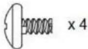
- Fix the 4pcs ground fixtures to 4pcs of lower support, using 4pcs screw M6 X 15.
Hardware Used

Screw M6 X 15
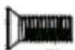
x 4

Ground Fixtures
×4

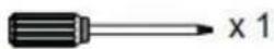
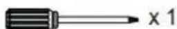
Philips screwdriver
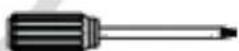
x1

text_image
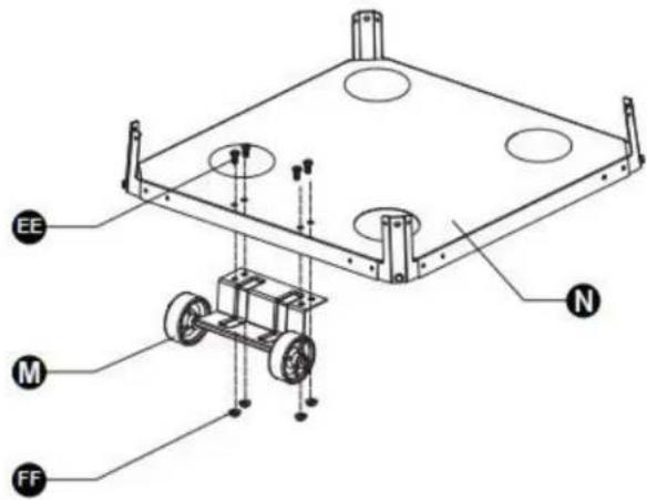
PP OO stinghou- Attach the wheel assembly to the bottom plate. Secure the wheel assembly to the bottom plate using 4 pieces of bolt M6 X12 and 4 pieces of flange nut M6.
Hardware Used

Bolt M6 X 12
x 4

M6 Flange nut
×4

Wrench
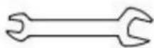
x 1
text_image
EE M FF N- Insert the pins of the base to the bottom holes of lower supports (K).
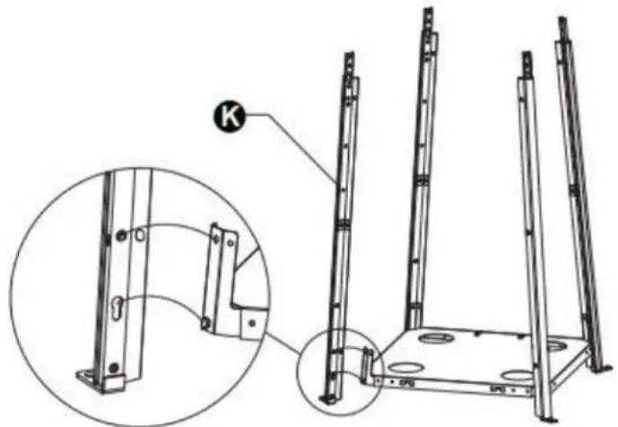
natural_image
Technical line drawing of a metal frame structure with mounting holes and a magnified inset showing detail (no text or symbols)- 4-1. Unscrew the switch button, insert the AA battery, and tighten the switch button.
4-2. Insert the pins of the control box assembly to the top holes of lower supports.
Hardware Used

AA Battery (1.5 V)
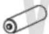
×1
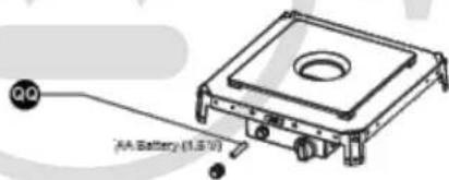
text_image
QQ AA Battery (1.5 V)
text_image
Technical diagram of a mechanical device with labeled parts (J, K) and an inset showing a close-up detail of the component.- Using 4pcs screw M5X12 screw to secure the lower supports and bottom plate.
Hardware Used

3/16" Screw

Philips screwdriver
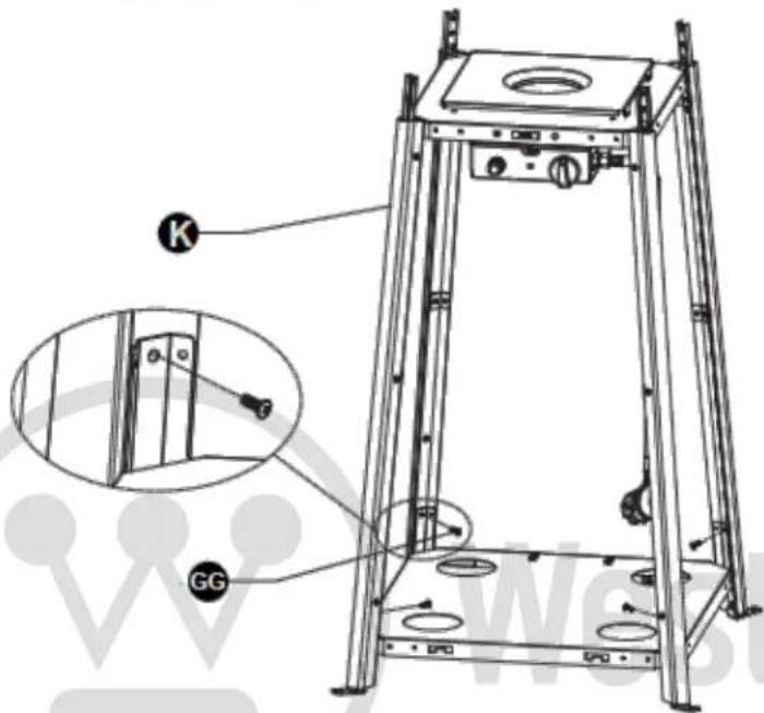
text_image
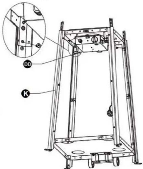
Technical diagram of a mechanical device with labeled components including 'K' and 'GG', showing structural components and mounting points.- Using 4pcs screw 3/16" to secure the lower supports and control box assembly.
Hardware Used

3/16" Screw
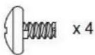

Philips screwdriver
text_image
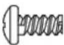
Technical diagram of a mechanical device with labeled components DD and K, showing structural components and a magnified inset view.- Assemble the block belt. Fasten the block belt to the 2 pieces lower supports
behind the front door using two M5X12 screws.
Hardware Used

Screw M5 X 12
x2

Philips screwdriver

x 1
natural_image
Technical line drawing of a mechanical testing apparatus with labeled components (L and GG), no readable text or symbols beyond labels.- Assemble the middle support. Insert the 4pcs upper supports to the lower support. Secure them with 8 pieces screws 3/16".
Hardware Used

3/16" Screw
x8

Philips screwdriver

x 1
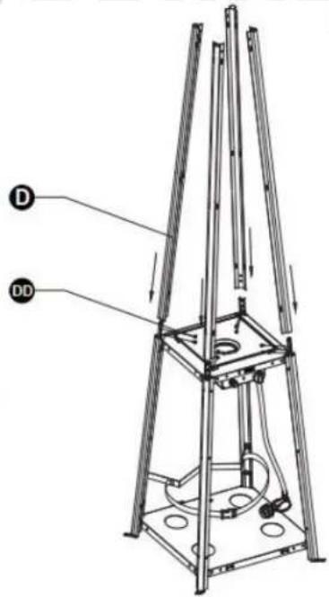
text_image
Technical diagram of a mechanical device with labeled components D and DD, showing structural supports and internal components.- Assemble the flame screen to the upper supports. Secure the flame screen to the upper support using 8pcs screw 3/16".
Hardware Used

3/16 ^th Screw
x8

Philips screwdriver
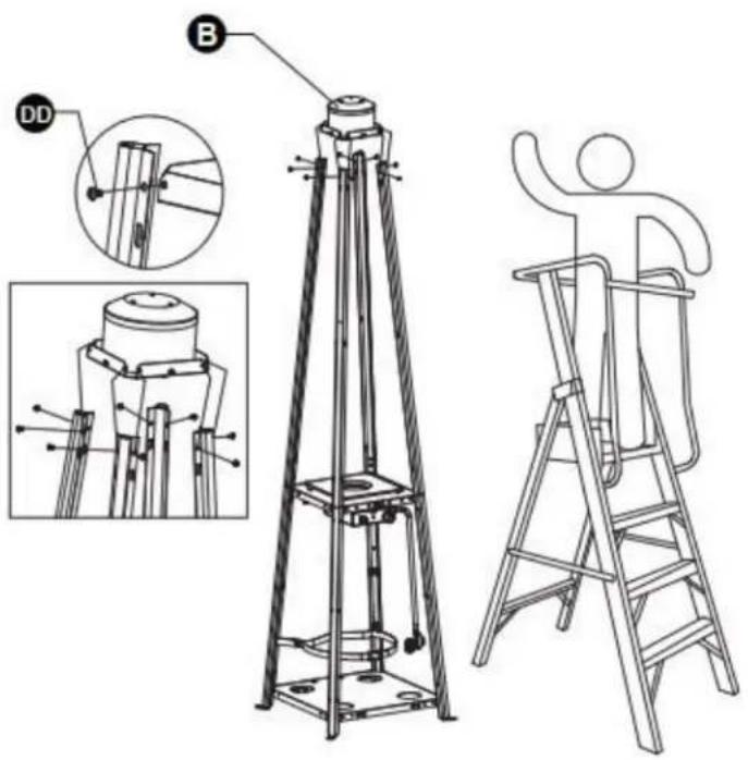
text_image
Technical diagram showing a surveying apparatus with labeled components and a person climbing a ladder, including detail views and component details.- Assemble the reflector onto the flame screen. Screw the 3 pieces studs onto the flame screen, place 3 pieces washers 6 on top of the studs, then attach the reflector to the studs, securing them with 3 pieces washers 6 and 3 pieces wing nut.
Hardware Used

Wing nut
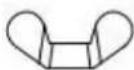
× 3

Washer Φ6
x6

Stud

x 3
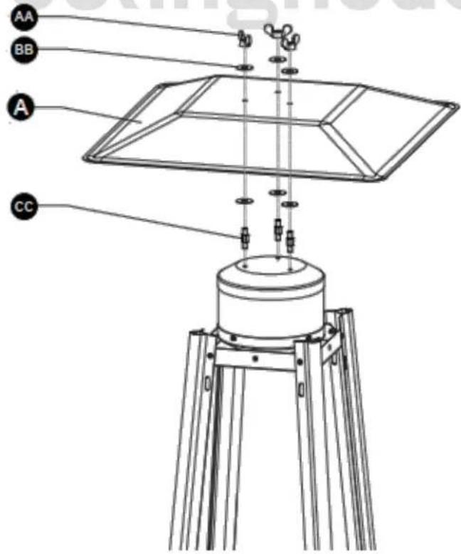
text_image
AA BB A CC- Carefully install the glass tube by lifting it and inserting it through the center hole in the upper plate. Ensure the black silicone ring is attached to the lower edge of the glass tube as illustrated. Slide the glass tube through the hole of the lower plate cover and onto the middle plate. Check and ensure that the glass tube is positioned properly and is completely covering the center hole of the middle plate.
WARNING! The black silicone ring must be in place prior to operating the heater.
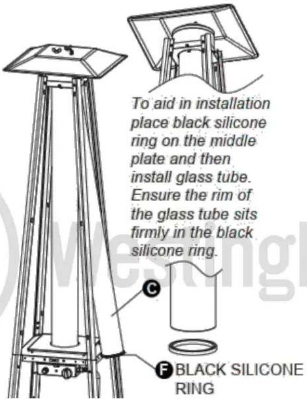
text_image
To aid in installation place black silicone ring on the middle plate and then install glass tube. Ensure the rim of the glass tube sits firmly in the black silicone ring. C F BLACK SILICONE RING- Assemble the protective guards. Hang the hooks of each protective guard on holes of upper supports.
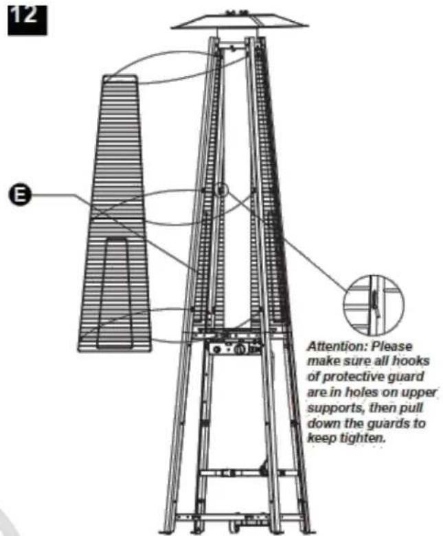
text_image
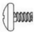
12 E Attention: Please make sure all hooks of protective guard are in holes on upper supports, then pull down the guards to keep tighten.- Unscrew half of the 4 pieces screws in the middle of the flame screen plate's four sides. Attach four fixing brackets to the flame screen plate with the 4 pieces 3/16" screws just unscrewed. The fixing brackets can fix the four protective guards.
Hardware Used

3/16" Screw
(PRE-ASSEMBLED)
x 4

Fixing
Bracket

×4

Philips
screwdriver

text_image
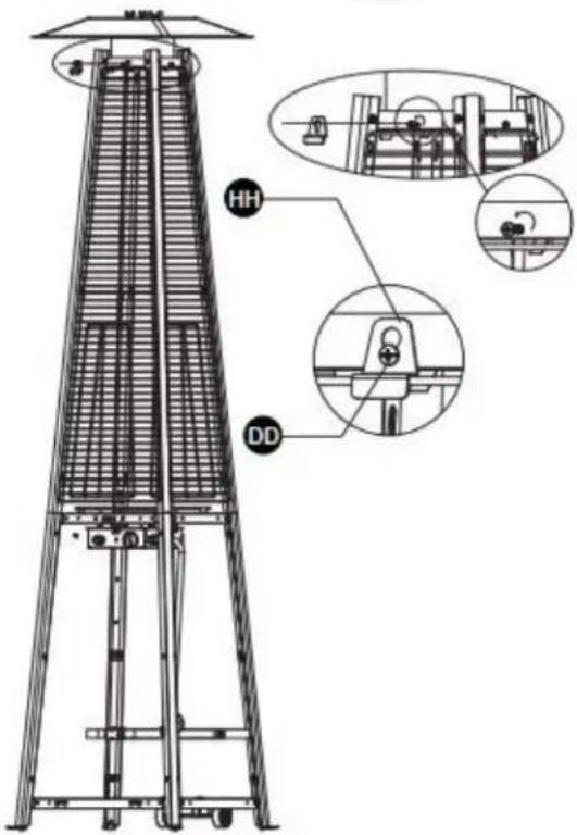
Technical diagram of a vertical ladder structure with labeled components HH and DD, including mechanical assembly details.- Attach the three side panels to the heater using 18pcs screw 3/16".
Note : Do not cover the front side where the control knob is.
text_image
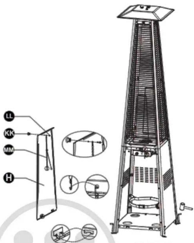
Hardware Used DD 3/16" Screw x 18 JJ Philips screwdriver x 1- Install the knob to M4X6 screw. Hang the chain to the hole on the control box assembly and place the pothook of front panel to the holes of bottom plate.
Note: Nails 1981-RTLL for anchoring the base securely to the ground are not inculded.
Hardware Used

Knob

x 1

Screw M4 X 6

x 1

Chain
x 1

Philips screwdriver
x 1
text_image
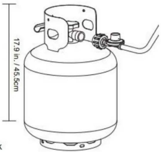
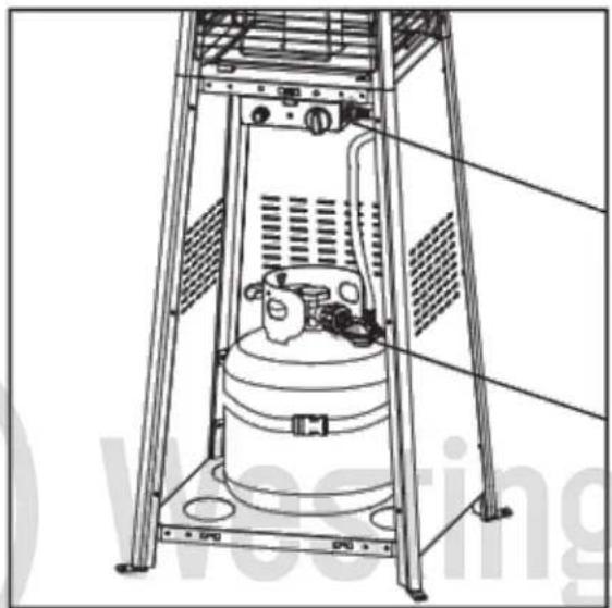
Technical diagram of a portable air conditioner tower with labeled components and internal wiring diagrams- Screw gas hose and regulator to propane cylinder (not included). Do not cross-thread.
Use a standard 20 lb. propane cylinder only (approximately 12.2 in. / 31cm. in diameter and 17.9 in. / 45.5cm high).
Every part of the heater shall be secure against displacement and shall be constructed to maintain a fixed relationship between essential parts under normal and reasonable conditions of handling and usage. Parts not permanently secured shall be designed so they cannot be incorrectly assembled and cannot be improperly located or misaligned in removing or replacing during cleaning or other servicing.
Use this heater only with a propane vapor withdrawal supply system. See chapter 5 of the standard for storage and handling of liquefied petroleum gas, ANS/NFPA 58. Your local library or fire department should have this book. Storage of an appliance indoors is permissible only if the cylinder is disconnected and removed from the appliance. A cylinder must be stored outdoors in a well-ventilated area out of the reach of children. A disconnected cylinder must have dust caps tightly installed and must not be stored in a building, garage or any other enclosed area. The maximum inlet gas supply pressure: 250 psi /1750 kPa. The minimum inlet gas supply pressure: 5 psi /35kPa. Manifold pressure with regulator provided: 11inch W.C/ 2.74 kPa.
The minimum hourly of 17000 Btu /4.98 kW is required input rating for an appliance for automatic operation at ratings less than full input rating. The pressure regulator and hose assembly supplied with the appliance must be used. The installation must conform with local codes, or in the absence of local codes, with national fuel gas code, ANS Z223.1/NFPA54, natural gas and propane Installation Code, CSA B149.1, or propane storage and handling code, B149.2.
A dented, rusted or damaged propane cylinder may be hazardous and should be checked by your cylinder supplier. Never use a propane cylinder with a damaged valve connection. The propane cylinder must be constructed and marked in accordance with the specifications for propane gas cylinders of the U.S Department of Transportation (DOT) or the standard for cylinders, spheres and tubes for transportation of dangerous goods and commission, CAN/CSA-B339. The cylinder must have a listed overfilling prevention device. The cylinder must have a connection device compatible with the connection for the appliance. The cylinder used must include a collar to protect the cylinder valve. Never connect an unregulated propane cylinder to the heater.
natural_image
Technical line drawing of a mechanical component with labeled parts (no readable text or symbols)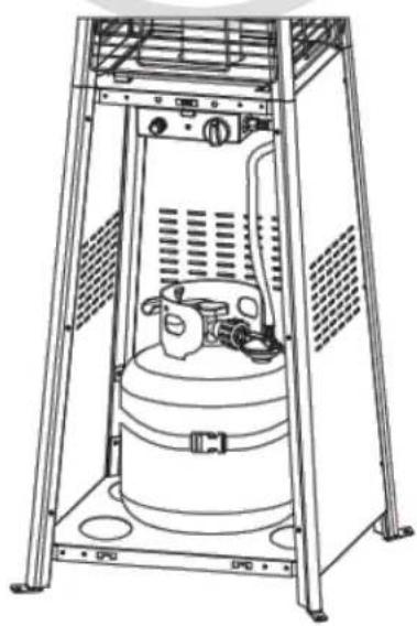
natural_image
Technical line drawing of a mechanical device with internal components and mounting brackets (no text or symbols)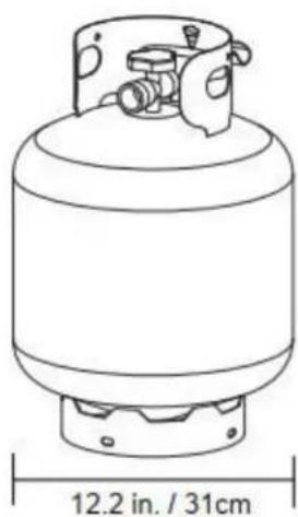
natural_image
Line drawing of a cylindrical gas cylinder with a side-mounted valve and base, labeled 12.2 in. / 31cm (no text or symbols on the diagram itself)Standard 20 lb. tank
text_image
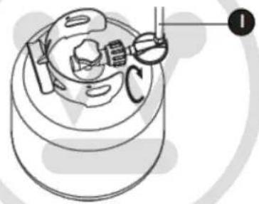
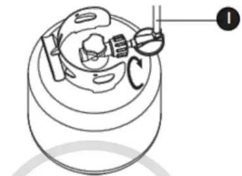
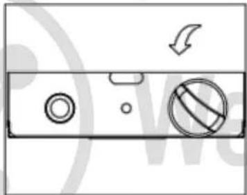
17.9 in. / 45.5cmThe knob on the propane tank must be closed. Make sure that the knob is turne
clockwise to a full stop. The cylinder supply system must be arranged for vapor withdrawal. Check that the control knob on the control unit is turned off. Hold the regulator in one hand and insert the nipple into the valve outlet. Be sure the nipple is centered in the valve outlet. The coupling nut connects to the large outside threads on the valve outlet. Hand-tighten the coupling nut clockwise until it comes to a full stop. Firmly tighten by hand only.
To Disconnect: Fully close the tank valve by turning clockwise. Turn the coupling nut counterclockwise until the regulator assembly detaches.
natural_image
Technical line drawing of a mechanical component with labeled parts (I, C), no readable text or symbols present.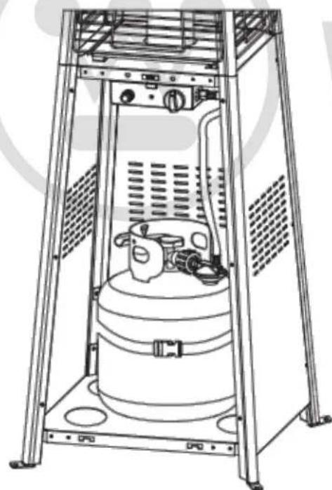
natural_image
Technical line drawing of a mechanical device with no visible text or symbolsDo not store a spare propane gas cylinder under or near this appliance.
Never fill the cylinder beyond 80 percent full.
Place the dust cap on the cylinder valve outlet whenever the cylinder is not in use. Only install the type of dust cap on the cylinder valve that is provided with the cylinder valve. Other types of caps or plugs may result in leakage of propane.
Leak Check
! WARNING
• Perform all leak tests outdoors.
- Extinguish all open flames.
• NEVER leak test when smoking.
- Do not use the heater until all connections have been leak tested and do not leak.
natural_image
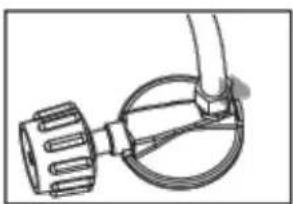
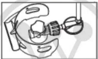
Technical line drawing of a mechanical component with no visible text or symbolsHose / Regulator connection
natural_image
Technical line drawing of a mechanical assembly with gears and components (no text or symbols)Regulator / Cylinder connection
natural_image
Technical line drawing of a mechanical device with no visible text or symbols- Make 2-3 oz. of leak check solution (one part liquid dishwashing detergent and three parts water).
- Apply several drops of solution where hose attaches to regulator.
- Apply several drops of solution where regulator connects to cylinder.
- Make sure all patio heater and light valves are OFF.
- Turn cylinder valve ON.
If bubbles appear at any connection, there is a leak.
- Turn cylinder valve OFF.
- If leak is at hose/regulator connection: tighten connection and perform another leak test. If bubbles continue appearing, the hose should be returned to the place of purchase.
- If leak is at regulator/cylinder valve connection: disconnect, reconnect, and perform another leak check. If you continue to see bubbles after several attempts, cylinder valve is defective and should be returned to cylinder's place of purchase.
If NO bubbles appear at any connection, the connections are secure.
NOTE: Whenever gas connections are loosened or removed, you must perform a complete leak test.
OPERATION INSTRUCTIONS
! DANGER
• CARBON MONOXIDE HAZARD
- For outdoor use only. Never use inside a house, or other unventilated or enclosed areas. This heater consumes air (oxygen). Do not use it in unventilated or enclosed areas to avoid endangering your life.
Caution: Do not attempt to operate until you have read and understand all General Safety Information in this manual and all assembly is complete, and leak checks have been performed.
This appliance shall be used only in a well-ventilated space and shall not be used in a building, garage or any other enclosed area.
An appliance may be installed with shelter no more inclusive than:
1) With walls on all sides, but with no overhead cover.
2) Within a partial enclosure which includes an overhead cover and no more than two side walls. These side walls may be parallel, as in a breezeway, or at right angles to each other.
3) Within a partial enclosure which includes an overhead cover and three side walls, as long as 30 percent or more of the horizontal periphery of the enclosure is permanently open.
Before Turning Gas Supply ON:
- Your heater was designed and approved for outdoor use only. Do NOT use it inside a building, garage, or any other enclosed area.
- Make sure surrounding areas are free of combustible materials, gasoline, and other flammable vapors or liquids.
- Ensure that there is no obstruction to air ventilation. Be sure all gas connections are tight and there are no leaks.
- Be sure the cylinder cover is clear of debris. Be sure any component removed during assembly or servicing is replaced and fastened prior to starting.
Before Lighting:
- Heater should be thoroughly inspected before each use, and by a qualified service person at least annually. If relighting a hot heater, always wait at least 5
minutes.
- Inspect the visible portion of the hose before each use of the appliance. If the hose leaks, it must be replaced prior to operation. Only use the replacement hose assembly specified by manufacturer.
- The pressure regulator and hose assembly supplied with the appliance must be used. Replacement pressure regulators and hose assemblies must be those specified by the appliance manufacturer.
Lighting:
Note: This heater is equipped with a pilot light that allows for safer startups and shutdowns. Pilot must be lit before main burner can be started.
- Turn the control knob to the "OFF" position.
- Fully open propane cylinder valve.
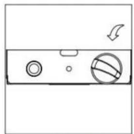
- Push control knob in and rotate to pilot position (Figure 1).
Note: For initial start or after any cylinder change, hold the control knob for 2 minutes to purge air from gas lines before proceeding.
natural_image
Pure electrical circuit lines without any symbolsFigure 1
text_image
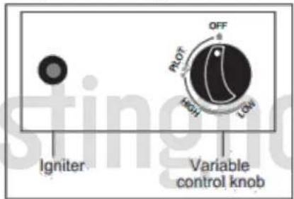
Igniter Variable control knob PLOT OFF KNOH LOWFigure 2
- Push and release the igniter button until pilot flame is visible through the glass tube.
- Once the pilot is lit, continue to press the control knob for 30 seconds.
- If the pilot does not stay lit, repeat steps 4 to 6.
- If after repeating steps 4 to 6 unit does not light, then
-Push in control knob and turn counterclockwise to "PILOT" (Figure 3).
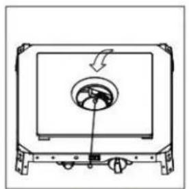
-As you are depressing the control knob, place long stem lighter through the glass tube to light the pilot (Figure 4).
-Repeat step 6.
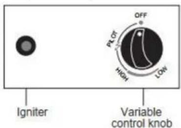
text_image
Igniter Variable control knob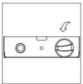
natural_image
Diagram of a washing machine handle with circular and ring components and a curved arrow indicating rotation (no text or symbols)Figure 3
natural_image
Diagram of a device with a circular component and directional arrow, no text or symbols presentFigure 4
natural_image
Simple line drawing of a device with circular ports and a basketball on the side (no text or symbols)Figure 5
- Push in and turn the control knob to the "HIGH", then release control knob. If you want a lower temperature, push in the control knob and turn counterclockwise to the "LOW" (Figure 5).
Note: Improper operation can cause injury or property damage. If the pilot fails to remain lit, all valves should be closed and a waiting period of at least 5 minutes should pass before attempting to light.
If you experience any ignition problem, please consult "Troubleshooting" on page 22.
Caution: Avoid inhaling fumes emitted from the heater's first use. Smoke and odor from the burning of oils used in manufacturing will appear. Both smoke and odor will dissipate after approximately 30 minutes. The heater should NOT produce thick black smoke.
Note: The burner may be noisy when initially turned on. To eliminate excessive noise from the burner, turn the control knob to the PILOT position. Then, turn the knob to the level of heat desired.
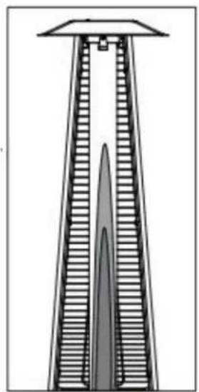
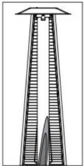
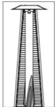
Note: In Normal conditions, the height of flame is 2/3 height of glass tube. Under Hi position. The height of flame is 1/3 height of glass tube. Under Low position, the flame is stable and bright. There should be no noise or black smoke.
natural_image
Cross-sectional diagram of a tall industrial chimney or chimney structure (no text or symbols)Normal
natural_image
Technical line drawing of a tall conical structure with hatched shading, no text or symbols presentAbnormal

WARNING
FOR YOUR SAFETY
Be careful when attempting to manually ignite this heater. Holding in the control knob for more than 10 seconds before igniting the gas will cause a ball of flame upon ignition.
When the heater is ON:
The flame should be blue with straight yellow tops. If excessive yellow flame is detected, turn off the heater and consult “Troubleshooting” on page 22.
Re-lighting:
Note: For your safety, the control knob cannot be turned OFF without first depressing control knob in PILOT position and then rotating it to OFF.
- Turn control knob to OFF.
- Wait at least 5 minutes, to let gas dissipate, before attempting to relight Pilot.
- Repeat the "Lighting" steps on prior page.

WARNING
FOR YOUR SAFETY
The heater will be hot after use. Handle it with extreme care.
Shut Down:
- Turn control knob clockwise to PILOT. (Normally, the burner will make a slight popping sound when extinguished.) Burner will extinguish but PILOT will remain ON.
- To extinguish PILOT, depress control knob and continue to turn it clockwise to OFF.
- Turn cylinder valve clockwise to OFF and disconnect regulator when heater is not in use.
Note: After use, some discoloration of the emitter screen is normal.
Operation Checklist
For a safe and pleasurable heating experience, perform this check before each use.
Before Operating:
-
Be familiar with the entire owner's manual and understand all precautions noted.
-
All components are properly assembled, intact and operable.
-
No alterations have been made.
-
All gas connections are secure and do not leak.
-
Wind velocity is below 10 mph.
-
Unit will operate at reduced efficiency below 40^ F.
-
Heater is outdoors (outside any enclosure).
-
There is adequate fresh air ventilation.
-
Heater is away from gasoline or other flammable liquids or vapors.
-
Heater is away from windows, air intake openings, sprinklers and other water sources.
-
Heater is at least 36 in. on top and at least 36 in. on sides from combustible materials.
-
Heater is on a hard and level surface.
-
There are no signs of spiders or insect nests.
-
All burner passages are clear.
-
All air circulation passages are clear.
-
Children and adults should be alerted to the hazards of high surface temperatures and should stay away to avoid burns or clothing ignition.
-
Young children should be carefully supervised when they are near the heater.
-
Clothing or other protective material should not be hung from the heater or placed on or near the heater.
-
Any guard or other protective device removed for servicing the heater must be replaced prior to operating the heater.
-
Installation and repair should be done by a qualified service person. The heater should be inspected before use and at least annually by a qualified service person.
-
More frequent cleaning may be required as necessary. It is imperative that control
compartment, burner and circulating air passageways of the heater be kept clean.
After Operation
-
Gas control is in OFF position.
-
Gas Tank valve is OFF.
- Disconnect Gas line.

WARNING
FOR YOUR SAFETY:
- Do NOT touch or move heater for at least 45 minutes after use.
- Reflector is hot to the touch.
- Allow reflector to cool before touching.
To enjoy years of outstanding performance from your heater, make sure you perform the following maintenance activities on a regular basis:
Keep exterior surfaces clean.
- Use warm soapy water for cleaning. Never use flammable or corrosive cleaning agents.
-
While cleaning your unit, be sure to keep the area around the burner and pilot assembly always dry. Do not submerge the control valve assembly. If the gas control is submerged in water, do NOT use it. It must be replaced.
a. Keep the appliance area clear and free from combustible materials, gasoline and other flammable vapors and liquids.
b. Do not obstruct the flow of combustion and ventilation air.
c. Keep the ventilation opening(s) of the cylinder enclosure free and clear from debris. -
Air flow must be unobstructed. Keep controls, burners, and circulating air passageways clean.
CARE AND MAINTENANCE
Visually checking portions of the hose assembly located within the confines of the heater post. Inspect the entire hose assembly at least annually, disassembling the reflector and burner. Inspect the hose assembly for evidence of excessive abrasion, cuts, or wear. Suspected areas should be leak tested.
Then assembling the reflector and burner again following with step 5 and 6.
Signs of possible blockage include:
Gas odor with extreme yellow tipping of flame.
The heater does NOT reach the desired temperature.
The heater glow is excessively uneven.
Teater makes popping noises.

Spiders and insects can nest in burner or orifices. This dangerous condition can damage heater and
render it unsafe for use. Clean burner holes by using a heavy-duty pipe cleaner.
Compressed air may
help clear away smaller particles.
Carbon deposits may create a fire hazard. Disassembly the reflector, unscrew the reflector spacer,
take off the screen, take down one side of protective guards. Then take the glass tube from the heater
and wash and clear. After that assembly the glass tube and the rest of parts.
Note: In a salt-air environment (such as near an ocean), corrosion occurs more quickly than normal.
Frequently check for corroded areas and repair them promptly.
TIP:
Use high-quality automobile wax to help maintain the appearance of your heater. Apply to exterior surfaces from the pole down. Do not apply to emitter screen or domes.
Storage Between uses:
Turn the control knob OFF.
Disconnect the propane cylinder.
Store heater upright in an area sheltered from direct contact with inclement weather (such as rain, sleet, hail, snow, dust and debris).
If desired, cover the heater to protect exterior surfaces and to help prevent build-up in air passages.
Note: Wait until the heater is cool before covering.
During periods of extended inactivity or when transporting: Turn the control knob to OFF.
Disconnect the propane cylinder and move to a secure, well-ventilated location outdoors.
Store heater upright in an area sheltered from direct contact with inclement weather (such as rain, sleet, hail, snow, dust and debris).
If desired, cover the heater to protect exterior surfaces and to help prevent build-up in air passages.
Never leave propane cylinder exposed to direct sunlight or excessive heat.
Note: Wait until heater is cool before covering.
Service
Only a qualified service person should repair gas passages and associated components.
Caution: Always allow heater to cool before attempting service.
TROUBLESHOOTING
| Pilot won’t lightNote: Heater operates at reduced efficiency below 40°F (5°C) | Cylinder valve is closed | Open valve |
| Blockage in orifice or pilot tube | Clean or replace orifice or pilot tube | |
| Air in gas line | Open gas line and bleed it (pressing control knob in) for not more than 1 - 2 minutes or until you smell gas | |
| Low gas pressure with cylinder valve fully open | Turn cylinder valve OFF and replace cylinder | |
| Igniter fails | Use match to light pilot; obtain new igniter and replace | |
| Pilot won’t stay lit | Dirt built up around pilot | Clean dirt from around pilot |
| Connection between gas valve and pilot assembly is loose | Tighten connection and perform leak check | |
| Thermocouple is not operating correctly | Replace thermocouple | |
| Burner won’t light | Propane cylinder is frosted over | Wait until the propane cylinder warms up and becomes unfrosted |
| Blockage in orifice | Clear blockage | |
| Control knob is not in ON position | Turn control knob to ON | |
| Burner flame is low | Gas pressure is low | Turn cylinder valve OFF and replace cylinder |
| Outdoor temperature is less than 40°F and tank is less than 1/4 full | Use a full cylinder | |
| Control knob fully ON | Check burner and orifices for blockage | |
| Carbon build-upThick black smoke | Dirt or film on reflector and burner screen | Clean reflector and burner screen |
| Blockage in burner | Remove blockage and clean burner inside and outside |
Warranty
ONE-YEAR LIMITED WARRANTY
This product is inspected, tested and carefully packaged to minimize the chance of damage during shipment. If a part within one year from the date of purchase proves to be defective in material or fabrication under normal use, the part will be repaired or replaced. The Company's obligation under the warranty is to replace or repair defective parts at our discretion. Any expenses or damage resulting from the installation, removal or transportation of the product will the responsibility of the owner and are not covered by this warranty. The owner assumes all other risks arising out from the use or misuse of the product. The warranty will be void if the product damage or failure is deemed by the Company to be caused by accident, alteration, misuse, abuse, incorrect installation or removal, or connection to an incorrect power source by the owner. The Company neither assumes, nor authorizes any person or entity to assume for it any obligation or liability associated with its products.
* Light bulbs and fuses are not covered under this warranty.
We also disclaim any liability for incidental or consequential damage. Some Canadian provinces do not allow the limitation of incidental or consequential damages. Therefore, these limitations may not apply to you. This warranty gives you specific legal rights. You may also have other legal rights which vary from province to province.
CUSTOMER SERVICE: 1-833-895-7333
It will be our pleasure to help you!
FRANÇAIS
text_image
Prohibition sign with pictograms of a car and houses, crossed out by a diagonal linetext_image
EE M FF Nnatural_image
Technical line drawing of a mechanical support structure with an inset showing a detail view (no text or symbols present)text_image
QQ AA-Ea20 (1.5 V) J Ktext_image
Technical diagram of a mechanical device with labeled components DD and K, showing structural components and a magnified inset view.text_image
Technical diagram of a heat exchanger or cooling tower with labeled components DD and Gtext_image
Technical diagram of a mechanical component with labeled parts and a numbered annotation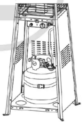
natural_image
Technical line drawing of a mechanical device with no visible text or symbolsnatural_image
Diagram of a hand holding a mechanical component with a circular base and gear-like shaft (no text or symbols)natural_image
Technical line drawing of a mechanical clamp or clamp device (no text or symbols)natural_image
Technical line drawing of a mechanical device with no visible text or symbolsnatural_image
Diagram of a device casing with circular components and directional arrow (no text or symbols)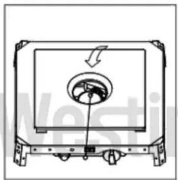
natural_image
Technical line drawing of a mechanical component with a circular feature and directional arrow (no text or symbols)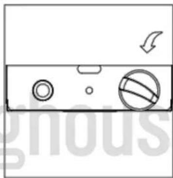
natural_image
Diagram of a refrigerator control panel with buttons and indicators (no text or symbols)natural_image
Diagram of a tall conical structure with horizontal slats and a pointed top (no text or symbols)Flamme normale
natural_image
Diagram of a tall tower structure with horizontal slats and a curved base (no text or symbols)Flamme anormale