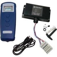
Thetis 7003 - Electrical Accessories Lofrans - Free user manual and instructions
Find the device manual for free Thetis 7003 Lofrans in PDF.


| Product type | Wireless metric counter for windlass (transmitter/receiver) |
| Brand | Lofrans |
| Model | Thetis 7003 |
| Dimensions (receiver) | 133 x 69 x 30 mm |
| Net weight (receiver) | 120 g |
| Power supply | 12 to 24 Vdc |
| No-load consumption | Max 100 mA |
| Max output current | 2 A (with short-circuit and overcurrent protection) |
| Operating temperature | -10°C to +60°C |
| Transmission frequency | 433 MHz |
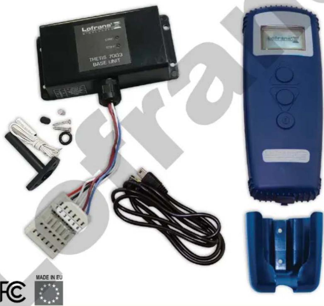
| Package contents | Transmitter, receiver with 4 screws, mains adapter for battery charging, magnetic sensor, magnet, sensor holder for horizontal windlass, cradle with 2 screws, female connector tool, manual |
| Main functions | Display of chain length paid out (meters/feet), speed, supply voltage, up alarm, reset, contrast and backlight programming, language selection |
| Maintenance and cleaning | Clean with a soft, dry cloth. Avoid abrasive products. Store in a dry, sheltered place. |
| Safety | Observe minimum distances from compass (30 cm), radio (50 cm), transmitters (2 m), radar beam (2 m). Install a 5 A fuse on the positive wire. |
| Spare parts and repairability | Use only original Lofrans accessories. Contact your local dealer or www.lofrans.com. |
| Warranty | 2 years from date of purchase for original buyer (subject to conditions). Register at www.lofrans.com/warranty.php. |
| Compliance standards | FCC Part 15, ETSI EN 301 489, EN 60950-1, EN 62479 |
| Country of origin | Italy |
Frequently Asked Questions - Thetis 7003 Lofrans
User questions about Thetis 7003 Lofrans
0 question about this device. Answer the ones you know or ask your own.
Ask a new question about this device
Download the instructions for your Electrical Accessories in PDF format for free! Find your manual Thetis 7003 - Lofrans and take your electronic device back in hand. On this page are published all the documents necessary for the use of your device. Thetis 7003 by Lofrans.
USER MANUAL Thetis 7003 Lofrans
Electric Accessories
CONSERVARE QUESTO MANUALE A BORDO STORE THIS MANUAL ON BOARD CONSERVER CE MANUEL A BORD DIESES HANDBUCH AN BORD AUFBEWAHREN GUARDAR ESTE MANUAL A BORDO
MANUALE DI INSTALLAZIONE E D'USO - INSTALLATION AND USER'S MANUAL MANUEL D'INSTALLATION ED D'UTILISATION - MANUAL DE INSTALACIÓN Y USO INSTALLATION UND BEDIENUNG
THETIS 7003

natural_image
Product display and wiring setup for a Lofrans 7003 Base Unit, featuring a blue digital device and cable connectors (no readable text or symbols)CE FC

Lofrans ^1 ®
WINDLASSES

THE ORIGINAL WINDLASS
Dear Customer,
Thank you for choosing a Lofrans product. Lofrans is a leader company in the production and worldwide distribution of nautical systems manufactured according to the most modern technologies, in compliance with international regulation requirements and the most important certifying bodies. All our products are manufactured with excellent materials suited for operations in marine environments and are subject to continuous checks to improve the qualitative levels and make them without any manufacturing defects. Together with such requirements, Lofrans anchor windlasses are a synthesis of reliability and efficiency, by guaranteeing the maximum performances during each phase of mooring, even in the most difficult. With a Lofrans product, years of reliable operations are guaranteed.
Lofrans©copyright, 2020. All rights reserved.
Lofrans declines any liability for possible inaccuracies due to print errors in this manual and reserves the right to introduce any changes deemed appropriate.
For this reason, Lofrans does not guarantee the accuracy of the manual after the date of issue and declines all liability for possible errors and omissions.
TABLE OF CONTENTS
1 INTRODUCTION 4
1.1 Purpose of the manual 4
1.2 Assistance 4
1.3 Receipt and storage 4
1.4 General notes 4
2 TECHNICAL DATA 4
2.1 Specifications 4
2.2 General dimensions 5
2.3 Contents of the package 5
3 INSTALLATION 6
3.1 Installing the magnet on the anchor windlass 6
3.2 Installing the magnetic sensor for horizontal shaft anchor windlasses 6
3.3 Installing the chain counter 7
4 MENU 7
4.1 Starting up 7
4.2 Chain counter setting menu 8
4.3 Measurement menu 8
4.4 Alarm and functions menu 8
4.5 Settings menu 9
4.6 Language menu 9
4.7 Sensor calibration menu 9
4.8 Table 1 - Standard series sensor 10
4.9 Check menu 10

5 USE 11
5.1 Measurement reset 11
6 TROUBLESHOOTING 11
7 WIRING DIAGRAM 12
8 WARRANTY CONDITIONS 12
8.1 Conditions and limitations 12
8.2 Exceptions 13
8.3 Liability 13
8.4 Procedure 13
8.5 Termination clause 13
8.6 Conformity 13
1 INTRODUCTION
1.1 Purpose of the manual
This manual will supply information on safety and correct use of the product. Follow these warnings carefully to avoid possible accidents or damages.

DANGER!
A warning such as this indicates the existence of a serious risk that has high probabilities to cause death or a serious accident if appropriate precautions are not taken.

ATTENTION!
A warning such as this indicates a reference to the application of safety practices, or draws the attention on unsafe behaviours that might cause personal injuries or damages to the boat.
1.2 Assistance
The Lofrans products are backed throughout the world by a network of authorised distributors and assistance. In case of need, please contact your local Lofrans distributor. Details on website www.lofrans.com
1.3 Receipt and Storage
Upon receipt of the package, verify the integrity of packing. Should it be necessary to store the product for a prolonged period, keep it in a dry and protected place.
1.4 General notes
The THETIS 7003 chain counter must be used solely for the purposes described herein, i.e. to operate and display the number of metres/feet of chain let out by an anchor windlass. Any other use is to be considered improper.
Any tampering with the instrument will result in immediate voiding of the warranty.
2 TECHNICAL DATA
2.1 Specifications
| Receiver | |
| Power supply from 12 to 24 Vdc | |
| No-load current intake max 100 mA | |
| Protection rating - | |
| Operative temperature -10 : +60 | |
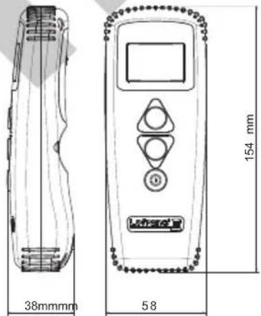
| Size (mm) 133 x 69 x 30 | |
| Weight (g) 120 | |
| Max output current* 2A | |
*Outputs have short circuit protection and over current protection
**Excluding cable connection zone
| Transmitter | |
| Rechargeable lithium-ion battery | |
| Duration in continuous duty 115 minutes | |
| Graphic display 128 x 64 pixel | |
| Protection rating IP 67 (Remote only)** | |
| Operative temperature -10 : +60 | |
| Max. chain length 999 metres – 999 feet | |
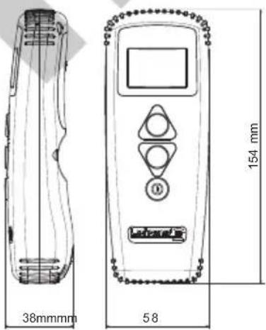
| Size (mm) 154 x 59 x 38 | |
| Weight (g) 100 | |
| Max communication distance at line of sight | >100m |
This product is in compliance with the following regulations:
| Draft ETSI EN 301 489-1 V2.2.2: 2019ETSI EN 301 489-3 V2.2.1: 2019ETSI EN 300 220-1 V3.1.1: 2017ETSI EN 300 220-2 V3.1.1: 2017 | EN 60950-1: 2016+A11: 2009+A1: 2010+A12: 2011+A2:2013EN 62479:2010FCC ID:2AUL7-02419 |
This device complies with part 15 of the FCC rules. Operation is subject to the following two conditions (1). This device may not cause harmful interference and (2) this device must accept any interference received including interference that may cause undesired operation
Federal Communication Commission Interference Statement
This equipment has been tested and found to comply with the limits for a Class B digital device, pursuant to Part 15 of the FCC Rules. These limits are designed to provide reasonable protection against harmful interference in a residential installation. This equipment generates, uses and can radiate radio frequency energy and, if not installed and used in accordance with the instructions, may cause harmful interference to radio communications. However, there is no guarantee that interference will not occur in a particular installation. If this equipment does cause harmful interference to radio or television reception, which can be determined by turning the equipment off and on, the user is encouraged to try to correct the interference by one of the following measures:
- Reorient or relocate the receiving antenna.
- Increase the separation between the equipment and receiver.
- Connect the equipment into an outlet on a circuit different from that to which the receiver is connected.
- Consult the dealer or an experienced radio/TV technician for help.
This device complies with Part 15 of the FCC Rules. Operation is subject to the following two conditions:
(1) This device may not cause harmful interference, and
(2) this device must accept an interference received, including interference that may cause undesired operation.
FCC Caution: Any changes or modifications not expressly approved by the party responsible for compliance could void the user's authority to operate this equipment.
IMPORTANT NOTE:
FCC Radiation Exposure Statement:
This equipment complies with FCC radiation exposure limits set forth for an uncontrolled environment. To maintain compliance with FCC RF exposure compliance requirements, please follow operation instruction as documented in this manual.
2.2 General dimensions
2.3 Contents of the package
The Radio Control Chain counter includes:
√ 1 Transmitter, radio-chaincounter
√ 1 Receiver, base unit with 4 screws
√ 1 m Micro USB cable for the charging the battery
√ 1 Magnetic sensor
√ 1 Magnet for the windlass
√ 1 Horizontal shaft anchor windlass sensor support
√ 1 Cradle with 2 screws for radio-chaincounter
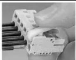
√ 1 Operating tool for female connector (see Fig.)
√ 1 User manual
natural_image
Close-up of a hand holding an electrical circuit breaker with wires nearby (no visible text or symbols)3 INSTALLATION
Recommended accessories
Use exclusively original Lofrans accessories and spare parts, designed and manufactured to ensure performances, duration and for keeping valid the warranty. For information on available spare parts, contact your local reseller or visit website www.lofrans.com
natural_image
Technical line drawing of a mechanical assembly with no visible text or symbols3.1 Installing the magnet on the anchor windlass
On a few models of anchor windlass the sensor and the magnet are already installed (chain counter setting). Therefore, the operations described below are not necessary.
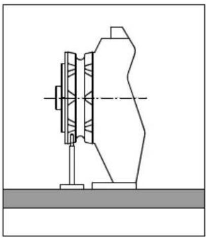
- A hole having a diameter of 7 mm (9/32") and depth of 12.5 mm (31/64") must be drilled on a tooth of the gypsy, in a place outside the chain's path.
- In the case of horizontal shaft anchor windlasses (see Fig.), drill the hole in the outer circumference of the gypsy.
- Also make sure that the protruding part of the magnet will not collide with the base or sensor during rotation of the gypsy.
- Insert the metal part of the magnet in the hole, allowing the protected part to protrude by about 2 mm. Fix it in place using an adhesive for metals (two component epoxy glue) or silicone. The glue used must be able to withstand a marine environment.
3.2 Installing the magnetic sensor for horizontal shaft anchor windlasses
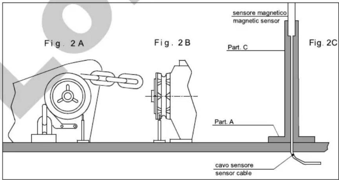
(see Fig. 2A-2B-2C)
Drill a 4 mm (\~3/16") hole in the cover through which to thread the sensor cable. Fasten Part A of the support with the two screws provided, after having positioned the O-ring in the lower part of the support. Cut Part C to measure using a hacksaw. The sensor must be positioned at a distance between 2 mm to 10 mm (5/64" to 25/64") from the magnet. Fit Part C with the magnetic sensor on support A and fix it in place using an adhesive for plastic (two-component epoxy glue) or silicone. Using the same glue, attach the sensor to Part C.
3.3 Installing the chain counter
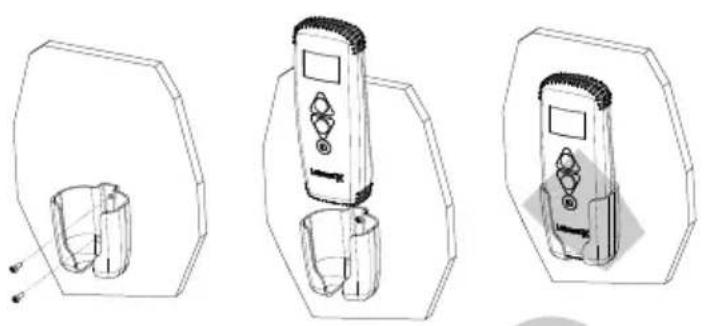
The chain counter must be positioned so that the display will be easy to read. It should not be exposed to direct sunlight. Secure the instrument in place with the cradle provided, tightening the two screws using a cross screwdriver.
natural_image
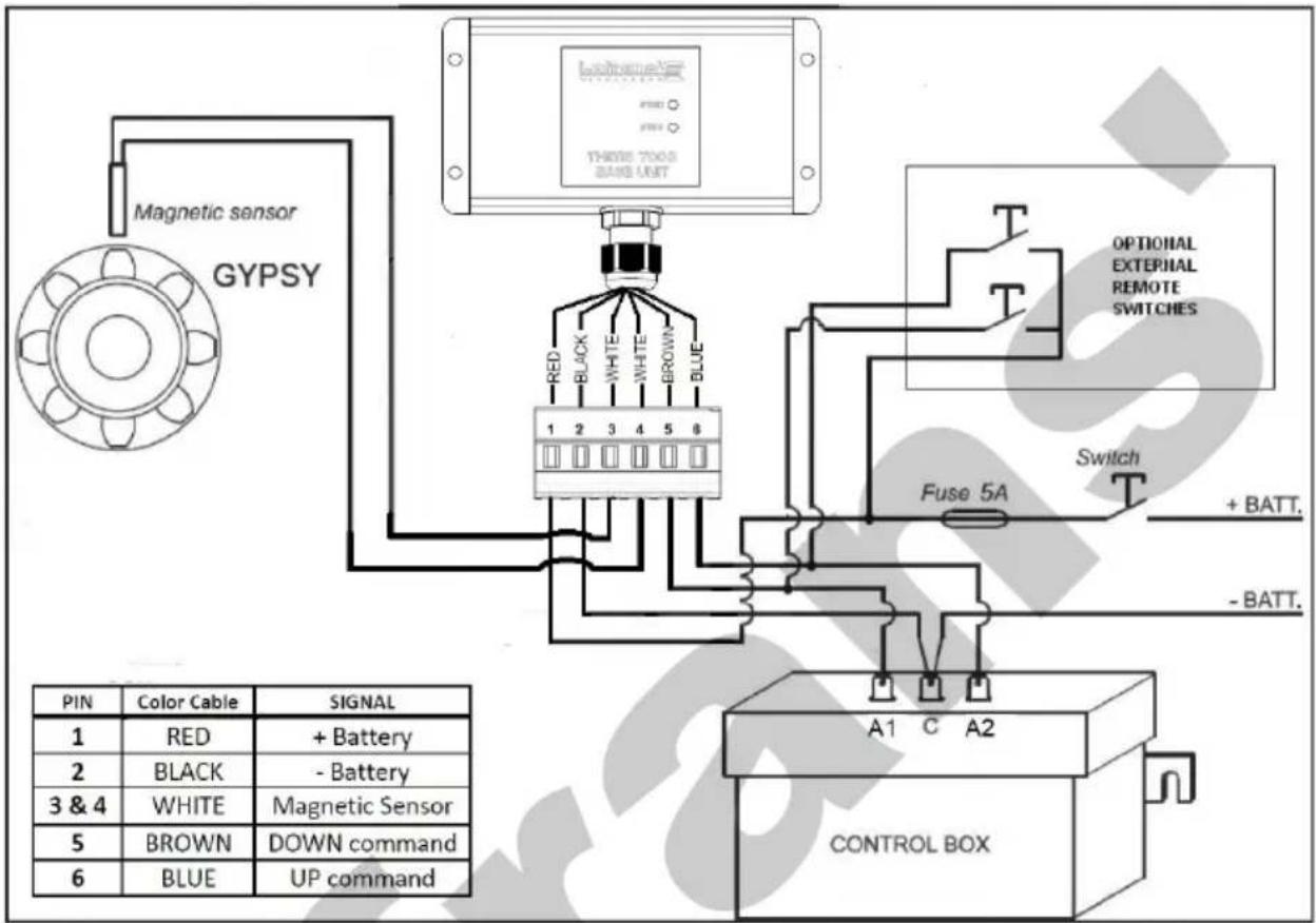
Three technical line drawings of a handheld device with cups, shown from different angles (no text or symbols)For instructions on making electrical connections, see Chapter 7- WIRING DIAGRAM. The wires must have a minimum cross section size of 1.5 mm². Install a 5 A (ampere) fast safety fuse on the positive (+) wire of the battery. Do not use the voltage generated by the engine battery set to provide power.
Series resistor recommended for >5m sensor cable length.
The instrument complies with EMC standards and must be positioned at a distance of:
- 30 cm (\~1 Ft) from the compass; -50 cm (\~1.5 Ft) from radio equipment;
- 2 metres (\~6.5 Ft) from radio transmitter equipment; -2 metres (\~6.5 Ft) from the radar beam.
- Transmission frequency 433MHz

4 MENU
4.1 Starting up
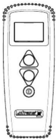
The chain counter features a graphic display and three keys: ON), (UP) and DOWN). There is also a buzzer that indicates the pressing of the keys or attracts the user's attention in particular conditions (alarm triggering). The ON key switches on the display and enables the other two keys. It must be used to access the parameter setting menus. For selecting the parameters to be modified and to confirm the values set. The display backlight will switch off 30 seconds after the last command given (adjustable default time – see "Light Time").
The UP key commands the hoisting of the anchor and the DOWN key casts it. When the key is released, the action is stopped. During parameter setting, the two keys allow the User to move around the menu and vary parameter values.
When switched on, the instrument will make a beep and the following page will appear for a few seconds:
Lofrans'
Once the initialisation procedure is complete, the main page will appear.
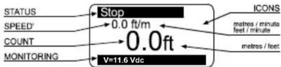
flowchart
graph LR
    A["STATUS"] --> B["Stop"]
    C["SPEED'"] --> D["0.0 ft/m"]
    E["COUNT"] --> F["0.0 ft"]
    G["MONITORING"] --> H["V=11.6 Vdc"]
    I["ICON"] --> J["metres / minute"]
    I --> K["feet / minute"]
    I --> L["metres / feet"]
Where:
STATUS: indicates the status of the instrument and any failure.
SPEED': indicates the chain speed during hoisting or lowering in meters per minute or feet per minute.
COUNT: indicates the measurement of the chain lowered (in metres or feet).
MONITORING: indicates the power supply voltage of the instrument and the power supply voltage of the boat.
ICONS: this is the part of the display bearing the icons that indicate the hoisting or casting of the anchor and any failure.
When the instrument is turned on for the first time, it will set up as programmed in the factory (see table).
4.2 Chain counter setting menu
| Hold down the (ON) key for six seconds to access the instrument setting menu. The following page will appear on the display: | 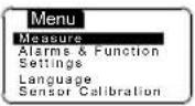 |
| Use the (DOWN) and (UP) keys to move around the menu options. | 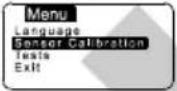 |
| Once you are positioned on the item to be modified press the (ON) key to confirm your choice. | |
| Use the (DOWN) or (UP) keys to move from one parameter to another. | |
| Once one is positioned on the parameter press the (ON) key to enable modification. | |
| According to the type of parameter, using the (DOWN) and (UP) keys it is possible to reduce/increase the value of the same or disable/enable the function. | |
| Once the modification has been performed, press the (ON) key to confirm. | |
| Using the (DOWN) key go to the Exit option and press the (ON) key again to return to the setting menu. The same procedure must be used to return to the main page. | |
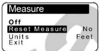
4.3 Measurement menu
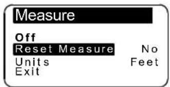
| Use the ▼ (DOWN) or ▲ (UP) key to move around the parameters | |
| OFFTurn the unit OFF | Confirm with 0 |
| Reset MeasurementResets the chain measurement value (0.0). | Select with 0▼ = Yes ▲ = NoConfirm with 0 |
| UnitsSelects the unit of measurement:Feet/ inchesMetres / centimetres | Select with 1▲ = Feet ▼ = MetresConfirm with 0 |
| ExitTo return to the settings menu. | Confirm with 0 |
4.4 Alarm and functions menu
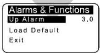
| Use the ▼ (DOWN) or ▲ (UP) key to move around the parameters | |
| Up AlarmIt is possible to enable the function and establish the height at which the anchor-winch stops; After you must release the up button to continue to other function.Settable values: 1.0 - 1.5 - 2.0...5.0 (metres or feet). | Select with ⒹSelect value with ▲ ▼Confirm with Ⓓ |
| Load DefaultThis function allows the User to revert to the original factory default settings, thus erasing all settings memorised.This command must only be used in the event of programming errors. | Select with Ⓓ▼ = Yes ▲ = NoConfirm with Ⓓ |
| ExitTo return to the settings menu. | Confirm with Ⓓ |
4.5 Settings menu
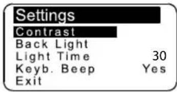
| Use the ▼ (DOWN) or ▲ (UP) key to move around the parameters | |
| ContrastBy enabling this function it is possible to start the display contrast programming procedure. | Select with ⒹSelect value with ▲ ▼Confirm with Ⓓ |
| Back LightBy enabling this function it is possible to start the display luminous intensity programming procedure (default value 120 seconds). | Select with ⒹSelect value with ▲ ▼Confirm with Ⓓ |
| Light TimeThis function allows the user to set the backlight on time during which the display remains lit after the last command given (default value 30 seconds). | Select with ⒹSelect value with ▲ ▼Confirm with Ⓓ |
| Keyboard BeepThis function allows the user to enable or disable the buzzer (emitted each time a key is pressed). | Select with Ⓓ▲ = Yes ▼ = NoConfirm with Ⓓ |
| ExitTo return to the settings menu. | Confirm with Ⓓ |

4.6 Language menu
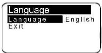
| Use the ▼(DOWN) or ▲(UP) key to move around the parameters | |
| Language*The user may select the display language:Italian, English, French, German, Spanish, Greek | Select with [IMAGE]Select value with  [IMAGE]Confirm with [IMAGE] [IMAGE]Confirm with [IMAGE] |
| ExitTo return to the settings menu. | Confirm with [IMAGE] |
*When the operator changes the language, the remote control will restart automatically.
4.7 Sensor calibration menu
| Standard Series Sensor Menu(magnet and sensor placed on gypsy) | 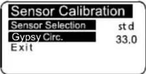 |
| Gypsy CircumferenceIn this row the user must enter the circumference of the gypsy (in centimetres or inches).Use the Table 1 provided to calculate the circumference.Settable values: centimetres or inches.Default value, 33 cm. | |
| Select with ⒹSelect value with ▲ ▼Confirm with Ⓓ | |
| ExitTo return to the settings menu. | |
4.8 Table 1 - Standard Series Sensor (magnet and sensor placed on gypsy)
| Chain type Number of recesses (R value) Gypsy | Circumference (G value) (cm) Gypsy Circumference (inches) | ||
| 6mm ISO 4565 / DIN 766 | 5 18,0 7,1 | ||
| 6 21,6 8,5 | |||
| 9 32,4 12,8 | |||
| 10 36,0 14,2 | |||
| 7mm ISO 4565 | 6 25,2 9,9 | ||
| 9 37,8 14,9 | |||
| 8mm ISO 4565 / DIN 766 | 5 24,0 9,4 | ||
| 6 28,8 11,3 | |||
| 7 33,6 13,2 | |||
| 8 38,4 15,1 | |||
| 10mm ISO 4565 | 5 30,0 11,8 | ||
| 6 36,0 14,2 | |||
| 7 42,0 16,5 | |||
| 10mm DIN | 5 28,0 11,0 | ||
| 6 33,6 13,2 | |||
| 7 39,2 15,4 | |||
| 12mm ISO 4565 & 13 DIN 766 | 5 36,0 14,2 | ||
| 6 43,2 17,0 | |||
| 13 DIN 764 5 45,0 | 17,7 | ||
| 14 pitch 42mm 5 42 | 0 16,5 | ||
| 5/16 HT 7 36,7 | 14,4 | ||
| 3/8" BBB 7 38,8 | 15,3 | ||
| 3/8" P.C. 6 44,2 | 17,4 | ||
| 1/2 BBB | 6 40,8 16,1 | ||
| 1/2 HT | 5 40,4 15,9 | ||
* factory setting of instrument 33,0
The table values are indicative.
For accurate gypsy Circumference value use formula (G value) = * R value*
Chain Internal Length
4.9 Check menu
Tests
Software Version 7
Operat.Time 0
Sensor Test
LCD Test
Exit
| Use the ▼ (DOWN) or ▲ (UP) key to move around the parameters | |
| Software VersionIndicates the version of the software installed. | |
| Operation TimeIndicates the time the instrument operates | |
| Sensor TestThe purpose of this function is to check the state of the sensor:Every pulse coming from receiver is momentary displayed to the screen | Select with 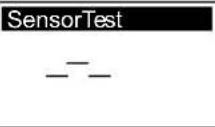 Confirm with Confirm with 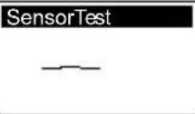 |
| LCD TestThis function switches on all the display's pixels thus making it possible to perform a check on them. | Select with  Confirm with Confirm with |
| ExitTo return to the settings menu. | Confirm with |
5 USE
Press the Ⓐ (ON) key to activate controls and to switch on the display lighting. The display lighting switches off 30 seconds after the last command given (adjustable default time – see "BkLight Time").
Press key ▲ (UP) to control the anchor ascending
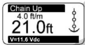
Press key ▼ (DOWN) to cast anchor
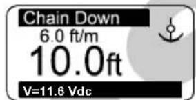
When any key is released (UP or DOWN) the corresponding action is stopped.
5.1 Measurement reset
Measurement reset is performed in the Measurement menu by selecting "Yes" in the Reset Measure row.

6 TROUBLESHOOTING
| FAULT CAUSE CORRECTIVE ACTION | ||
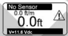 | Though UP or DOWN keys are pressed, the instrument doesn't receive any signal from the magnetic sensor for more than 5 seconds. | Check the sensor electric connections.Check if sensor operates properly.If not, replace it.Check the position of sensor and magnet on gypsy and their distance.Check the operation of electric installation or anchor windlass. |
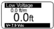 | The instrument's power supply voltage is lower than10Vdc. | Verify the battery charge or operation of the electricssystem. |

7 WIRING DIAGRAM
flowchart
graph TD
    A["Handover Sensor"] -->|Magnetic sensor GYPSY| B["1"]
    A -->|Magnetic sensor GYPSY| C["2"]
    A -->|Magnetic sensor GYPSY| D["3 & 4"]
    A -->|Magnetic sensor GYPSY| E["5"]
    A -->|Magnetic sensor GYPSY| F["6"]
    B --> G["Blue"]
    C --> H["Brown"]
    D --> I["Magnetic Sensor"]
    E --> J["Brown"]
    F --> K["UP command"]
    G --> L["Fuse 5A"]
    H --> M["Switch"]
    I --> N["CONTROL BOX"]
    J --> O["+ BATT."]
    K --> P["- BATT."]
    L --> Q["A1 C A2"]
    M --> R["A1 C A2"]
    N --> S["A1 C A2"]
8 WARRANTY CONDITIONS
Lofrans' warrants that in normal use and observing the maintenance schedules, the product is covered by warranty for a period of 2 years from the date of purchase by the original purchaser, without prejudice to the conditions, limitations and exceptions listed below. Any product that proves defective in normal use during said period shall be repaired or replaced, as Lofrans' chooses.
8.1 Conditions and limitations
- Lofrans' does not assume any responsibility for an incorrect choice of product made by the purchaser.
- The responsibility of Lofrans' shall be limited to the repair or replacement of all parts of the product that originally present material and/or manufacturing defects.
-
Lofrans' shall not in any way be liable for faults or any consequent damage originating from:
-
use of the product in applications for which it was not designed;
- corrosion, degradation caused by ultraviolet rays and wear;
- failure to follow the maintenance schedule;
- incorrect or unsuitable product installation;
- any modification or alteration of the product;
- conditions of use exceeding the product specifications.
- The warranty does not cover the additional costs borne for interventions, removal, transport and installation of the product;
- The warranty is cancelled if maintenance is carried out by people not authorized by Lofrans'.
- Lofrans' products are designed to be used only in the marine environment. Lofrans does not assume any responsibility deriving from other uses.
- Lofrans' reserves the right to not acknowledge this warranty if the electromechanical products are operated by unsuited electrical accessories and/or in the case of failure to install an appropriate overload cutout switch on the electric power line.
8.2 Exceptions
Coverage under warranty is limited to a period of 1 year from the date of purchase by the original purchaser for:
- Electrical boards
- Gaskets and seals
- All the products used on charter boats.
8.3 Liability
This warranty does not cover any loss or damage caused to the purchaser by the ascertained non-conformity of the product, except for the case of fraud or gross negligence of Lofrans' declared with a court ruling.
Some states and countries do not allow the exclusion or limitation of incidental or consequential damages, so the above-stated limitations or exclusions might not be applicable.
8.4 Procedure
The warranty application must be notified to Lofrans website http://www.lofrans.com/warranty.php by filling all the necessary fields, including the serial number of the control.
8.5 Termination clause
If any clause of this warranty is invalidated by a judge or other competent authority, the validity of the remaining clauses of this warranty and the rest of the clause in question will not be affected.
8.6 Conformity
This warranty is governed by the laws and in conformity with Italian laws. The Court of Milan has jurisdiction over all disputes.

Gentile cliente,
natural_image
Close-up of hands holding a white electrical component with wires (no visible text or symbols)3 INSTALLAZIONE
natural_image
Technical line drawing of a mechanical assembly with no visible text or symbolsnatural_image
Technical line drawing of a mechanical component with a cylindrical housing and mounting holes (no text or symbols)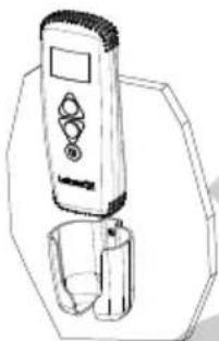
natural_image
Line drawing of a handheld device with a glass and a digital display (no text or symbols)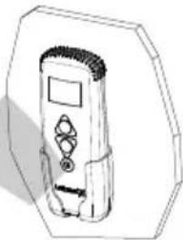
natural_image
Line drawing of a handheld electronic device with control panel and buttons (no text or symbols)Lofrans'
2.2 General dimensions
natural_image
Close-up of hands holding a small electronic component with wires (no visible text or symbols)3 INSTALLATION
natural_image
Technical line drawing of a mechanical assembly with no visible text or symbolsnatural_image
Three technical line drawings of a handheld device with cups, shown from different angles (no text or symbols)
8 CONDITIONS DE GARANTIE
natural_image
Close-up of hands holding a white electrical circuit breaker with wires (no visible text or symbols)3 INSTALLATION
Empfohlenes Zubehör
natural_image
Three technical line drawings of a mobile phone device with a cup, shown from different angles (no text or symbols present)natural_image
Close-up of a hand holding an electrical component with wires in the background (no visible text or symbols)3 MONTAJE
natural_image
Technical line drawing of a mechanical assembly with no visible text or symbolsnatural_image
Three technical line drawings of a mobile phone device with a cup, shown from different angles (no text or symbols present)natural_image
Line drawing of a handheld electronic device with control buttons and display (no text or symbols)
- Electric Accessories
- THETIS 7003
- Dear Customer,
- Lofrans©copyright, 2020. All rights reserved.
- TABLE OF CONTENTS
- INTRODUCTION 4
- TECHNICAL DATA 4
- INSTALLATION 6
- MENU 7
- INTRODUCTION
- Purpose of the manual
- DANGER!
- ATTENTION!
- Assistance
- Receipt and Storage
- General notes
- TECHNICAL DATA
- Federal Communication Commission Interference Statement
- IMPORTANT NOTE:
- FCC Radiation Exposure Statement:
- General dimensions
- Contents of the package
- INSTALLATION
- Recommended accessories
- Installing the magnet on the anchor windlass
- Installing the magnetic sensor for horizontal shaft anchor windlasses
- Installing the chain counter
- MENU
- Starting up
- Lofrans'
- Chain counter setting menu
- Measurement menu
- Alarm and functions menu
- Settings menu
- Language menu
- Sensor calibration menu
- Check menu
- Tests
- USE
- Measurement reset
- TROUBLESHOOTING
- WIRING DIAGRAM
- WARRANTY CONDITIONS
- Conditions and limitations
- Exceptions
- Liability
- Procedure
- Termination clause
- Conformity
- Gentile cliente,
- INSTALLAZIONE
- CONDITIONS DE GARANTIE
- Empfohlenes Zubehör
- MONTAJE
Brand : Lofrans
Model : Thetis 7003
Category : Electrical Accessories