51831T - Grass trimmer TORO - Free user manual and instructions
Find the device manual for free 51831T TORO in PDF.

| Product type | String trimmer |
| Brand | Toro |
| Model | 51831T |
| Rated voltage | 60 V DC max, 54 V nominal |
| Battery type | Rechargeable lithium-ion |
| Battery capacity | 2.0 Ah, 108 Wh |
| Battery model | 88620 |
| Charger model | 88610 |
| Cutting width | 33 cm (13 in) or 38 cm (15 in) depending on adjustment |
| Line diameter | 2.0 mm (0.08 in) |
| Line type | Nylon monofilament |
| Line feed | Automatic bump feed and manual feed |
| Auxiliary handle | Yes, adjustable |
| Safety guard | Deflector and protective cover |
| Locking system | Lock trigger and battery lock |
| Battery operating temperature | Between 0 °C and 49 °C (32 °F to 120 °F) |
| Battery charging temperature | Between 5 °C and 40 °C (41 °F to 104 °F) |
| Maintenance | Clean after each use, do not immerse, check fasteners |
| Spare parts | Use only genuine Toro parts |
| Repairability | Take to an authorized service dealer |
Frequently Asked Questions - 51831T TORO
User questions about 51831T TORO
0 question about this device. Answer the ones you know or ask your own.
Ask a new question about this device
Download the instructions for your Grass trimmer in PDF format for free! Find your manual 51831T - TORO and take your electronic device back in hand. On this page are published all the documents necessary for the use of your device. 51831T by TORO.
USER MANUAL 51831T TORO
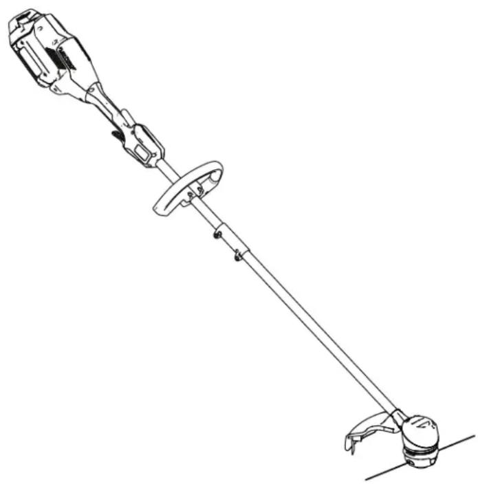
EN Flex-Force Power System™ 13in or 15in MAX String T rimmer
51831, 51831T
ES Desbrozadora de (13") o 38 cm (15") System™
51831 , 51831T
FR Débroussailleuse System™ 60 V MAX cm (15 po)
51831, 51831T
Operator's Manual
Flex-Force Power System 13in or 15in 60V MAX String T rimme
Model No. 51831 —Serial No. 323000001
Model No. 51831T
and
—Serial
natural_image
Technical line drawing of a mechanical clamp or lever device with no visible text or symbols
For assistance, please see www .T oro.com/support for instructional videos or contact 1-888-384-9939 before returning this product.
Whenever manufacturer an Authorized Customer numbers the location product.
you need parts, Service or Service and of your product of the model W rite the numbers
Important: scan the equipped) product
QR to access information. W ith your on
⚠️ W ARNING
CALIFORNIA Proposition 65 W arning
| The power cord lead, California or other hands | on chemical to reproductive after | this product | |
| Use to California or other | of chemicals this product to cause reproductive | known | |

contains to the State birth defects harm. W ash
handling.
may to cancer
1 cause the harm. State birth exposure of defect:
Introduction
| This homeowners designed These by T oro products could | trimmer battery 60V for prove | is intended to trim use T oro packs lithium-ion purposes dangerous |
| Model charger | 51831T . | does |
Figure 1 by residential grass Model as and needed serial number 60V lithium-ion battery are designed to be charge battery chargers. Model other than their intended to you and bystanders. Serial not include a battery
Read this information and maintain your injury and product operating the product
carefully to learn how product properly and to damage. Y ou are responsible properly and safely for product safety and accessory your information, product.
Safety-Alert Symbol
The safety-alert symbol ( Figure 2 ) shown in this manual and on the machine identifies important messages that you

Figure
Safety-alert
2
g000502
symbol
| The safety-alert that alerts is followed CAUTION | you by | to the | symbol unsafe word |
| DANGER | indicates | ||
| which, injury | if | not | avoided, |
| W ARNING which, injury | if not | indicates avoided, |
| CAUTION | indicates | ||
| which, injury | if | not | avoided, |
| This information. mechanical information | manual | uses Important information worthy | two |
Safety
IMPORT safety
must follow INSTRUCTIONS to
ANT
prevent
e
⚠️ W ARNIN
| When read instructions shock, | using and and | electric follow to personal | basic reduce |
following:
Read appears actions All or Instructions
I. T DANGER training
| 1. | The operator of the an accidents or hazardous will property result in death or |
| 2. | Do not allow children | ||
| a too potentially battery | hazardous or | ||
| couulations result | imay death | restrict | |
| 3. | Do not | allow | children |
| a | operate | or | service |
| potentially | hazardous | ||
| who | responsible | minor | |
| result | in | and | |
| instructions, | physic | ||
| or | service | the |
| 4. | otherBeforecallschargerandmarkingsspecial | wordsusingattentionNote'onattention. | totheall themethesesthely | highlghttothepr |
| 5. | Become of the tool, | familiar battery | with pack |
II. Preparation
| 1. | Keep operating | bystanders area. | a | |||
| 2. | Use Using increase | only other | the | battery accessories | ||
| the | risk | of | in | |||
| 3. | Plugging | the | battery | |||
| not | 120 | V | can | cause | ||
| not | plug | the | battery | |||
| than | 120 | V | . | For | a dif | |
| use | an | attachment | ||||
| configuration | for | the | ||||
| 4. | Do not use a damaged pack or battery charger unpredictable explosion, or risk of |
| 5. | If the supply damaged,to replace | cord contact it. | to an |
| 6. | Charge charger | the specified | battery | by |
1 type of battery pack may create a risk of fire12. when used with another battery pack.
- Charge only
the battery
- Follow not charge temperature Otherwise, and increase
all charging the battery range you may the
- Do not other safety functioning
operate the protective properly
- Dress including slip-resistant hearing not wear get caught dusty operating
properly—W eye protection; footwear; protection. loose clothing in moving conditions.
III. Operation
-
A void dangerous tool in rain or in damp
-
Use the proper tool the tool for purposes could prove dangerous
-
Prevent unintentional switch is in the O FF to the battery pack not carry the tool w or energize the tool position.
-
Operate the tool light.
-
If the tool strikes immediately to stop, shut parts examining necessary the repair
-
Remove the battery adjusting it or changing
-
Keep area and your all hands moving
-
Shut of f the tool, the tool, and wait adjusting, servicing,
-
Remove the battery you leave it unattended.
-
Do not force the job better and safer designed.
-
Do not overreach—Keep balance at all times, never run with the tool.
Stay common use the in back of alcohol alert—W sense tool while a well-ventilated or drugs. atch when ill,
-
instructions ensure that and the doventil clear pack of debris outside of the
-
specified Under damage liquid; the abusive battery condition of fire come into contact with water without If the liquid guards contains medical devices help. in place a park the may tool. cause irritation
-
earo appropriate expose a cloth excessive long pantemperature. substanti temperature rubber gloves above and Texposion back long hair and
- or loose jewelry mistrea parts W ear a dust m present a risk of fire, m burn.
- Do not disassemble environments—Do - Replace the battery or wet locations. T oro battery pack for battery your application—Using may other pack - Keep to an its intended packs children battery and bystanders. you starting—Ensure ready to use position are before connecting
I. and . Maintenance the tool. and 1. your finger the on the swi with maintain switch the on the with in good repair for the best reduce the risk of injury only for in lubric daylight or and good cha handles dry , clean, a
an 2. object or the starts battery to vibration of f away tool, from wait metal for albojected disconnects, keys, the battery and for connection damage. Make 1 altern before battery resuming terminals operation
-
Rack from your hands tool and parts. accessories.
-
and parts. Shut feet of away the from the removal, the tool, and wait for remove adjusting, the battery servicing, pack r all movement Check the or tool to stop d are cleaning, damaged guards whetack from it will the operate w misaligned and binding
tool—Paw, mounting, the tool and at may the afate fect for its operation. it instructions, have and repair or replace footing and 6. especially not replace on slopes. the means on the tool with
| 7. Do not attempt to service or repair the tool,battery pack, or battery charger except asindicated in the instructions. Have Service replacement safely maintained. | ||||||||||
| Dealer | an perform parts to ensure | authorized service that using the product | ||||||||
| 8. Store secure, | an and idle out tool of indoor reach | in a place of children. that | ||||||||
| 9. Do not dispose cell may possible special | tof the Check disposal | battery with instructions. | in a local fire. codes | |||||||
SA VE THESE INSTRUCTIONS
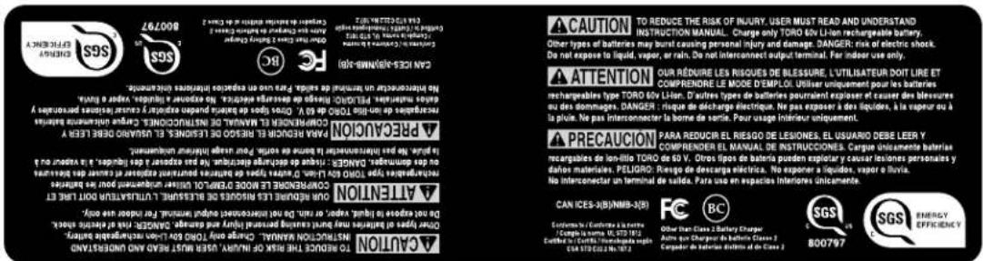
Safety and Instructional Decals

Safety decals and instructions are easily visible to the operator and are located near any area of potential danger. Replace any decal
decal144-3094

144-3098
decal144-3098
144-3094
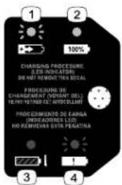
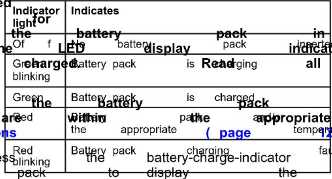
- The battery charging.
3.pack The is battery or under temperature
the
pack appropriate range.
is over
-
The battery charged.
-
Battery pack is fully charging
fault
144-3096
decal144-3096

139-5346
decal139-5346

decal144-3084
144-3084

144-3085
decal144-3085

140-8475
decal140-8475
- Read the Operator's Manual.
-
Call2Recycle® battery recycling program
-
Keep away from open fire or flames.
- Do not expose to rain.

natural_image
Black rectangular object with a circular indicator and four small square buttons on top (no text or symbols)137-9461
decal137-9461
- Battery
charge
status

139-5210
decal139-5210
- W arning—read
moving
do
广力云
not
parts;
operate
keep
in
the
all
wet
Operator
guards
conditions.
's Manual
in place;
; stay away
wear eye prot
Setup
Loose Parts
Use the chart below to verify that all parts have been shipped.
| Procedure Description | Qty . | Use | |
| 1 | Allen wrench 1 | Unfold the handle. | |
| 2 | Auxiliary handle assemblyScrewdriver (not) | 1Install the auxiliary handed) | |
| 3 | GuardScrewdriver (not) | 1- included) | Install the guard. |
Important:
first time,
The
refer
battery
to
Charging
pack
is
the
not
Battery
I
1
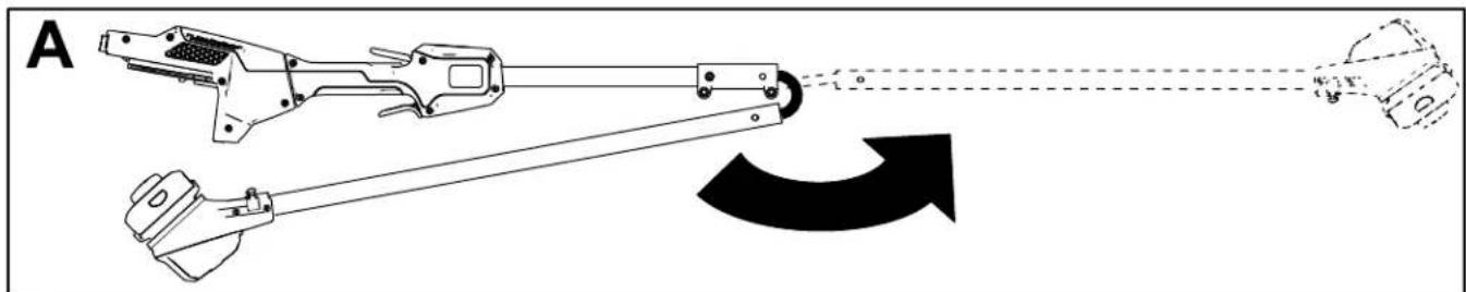
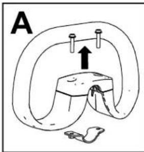
Unfolding the Handle
Parts needed for this procedure:
1 Allen wrench
Procedure
- Unfold the handle (A of Figure 3).
- Align the locking button on the lower shaft together (B and C of Figure 3).
Note:
The
locking
[Non-Text]
button
clicks
into
the
- Using the provided Allen wrench, tighten
natural_image
Technical line drawing of a mechanical device with no visible text or symbols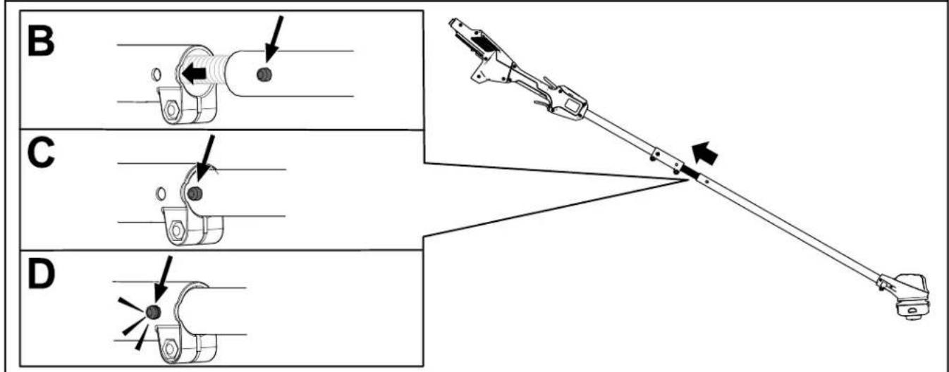
Figure
3
g330169
2
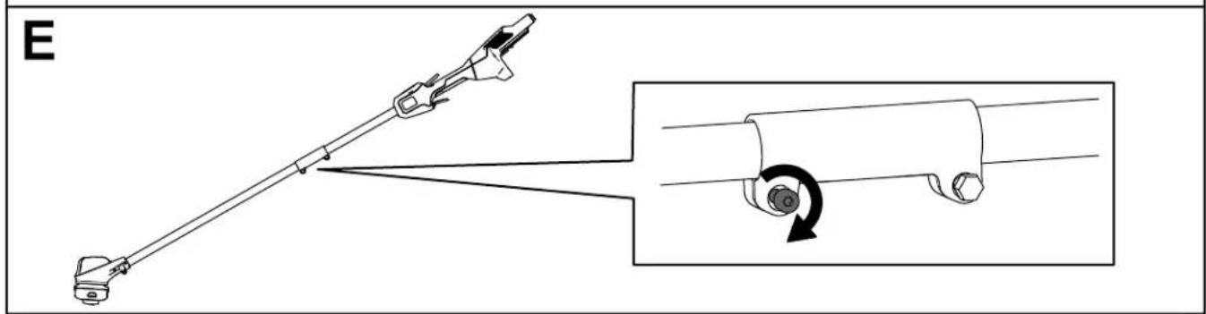
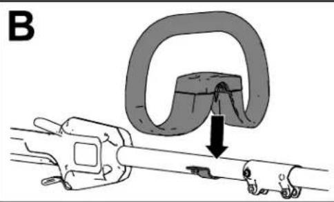
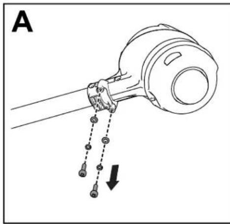
Installing the Auxiliary Handle
Parts needed for this procedure:
| 1 Auxiliary handle assembly | |
| - | Screwdriver (not included) |
Procedure
| 1. | Using the 2 | a screws | Phillips (A of Figure) | head | screwdriver 4). | , separate | ||
| 2. | Line | up | the | auxiliary | handle | with | auxiliary | |
| 3. | Secure | the | auxiliary | handle | to | the | handle |
natural_image
Mechanical diagram showing a clamp or bracket being inserted into a tool, with no visible text or symbols.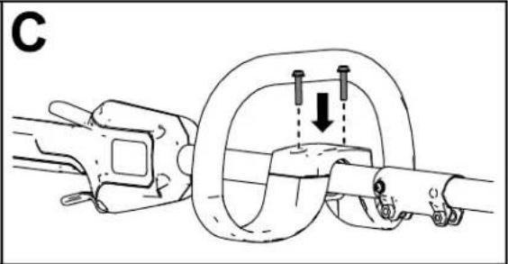
natural_image
Mechanical diagram showing a rope knot with two bolts and a downward arrow indicating motion (no text or symbols)Figure
4
g331072
3
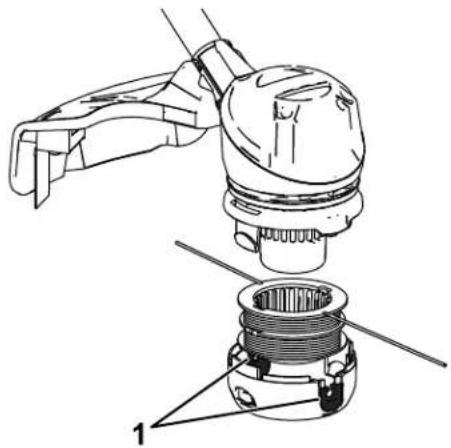
Installing the Guard
Parts needed for this procedure:
| 1 | Guard |
| - | Screwdriver (not included) |
Procedure
- Using base (A of Phillips Figure head 5). screwdriver, remove
- Align the guard onto the trimmer base (B)
- Secure the guard onto the base of the trim removed (C of Figure 4).
natural_image
Diagram of a mechanical device with hanging weights and a dashed line indicating motion (no text or symbols)
natural_image
Technical diagram showing a mechanical assembly with a cylindrical component and a cross-sectional view of a mechanical part (no text or symbols)
natural_image
Mechanical assembly diagram showing linkage mechanism with no text or symbolsFigure 5
g330190
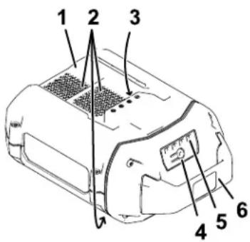
Product Overview
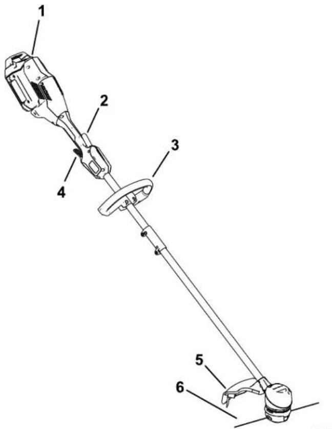
Figure 6
- Battery latch 4. Run trigger
- Lockout trigger 5. Guard
- Auxiliary handle 6. String
g330065
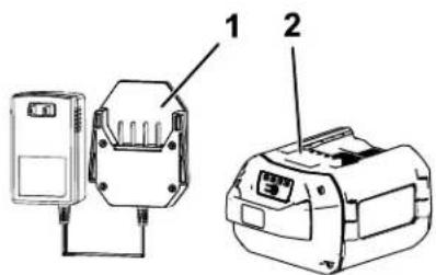
Figure 7
-
Battery charger Model 88610 (included with Model 51831)
-
Battery pack Model 88620 (included with Model 51831)
Specifications
| Model | 51831/T | ||
| Rated V oltage | 60V DC maximum, | ||
| Charger T ype | T oro 60V lithium-ion | ||
| Battery | T ype T oro 60V | ||
\$4
[Non-Text]
lithu
Appropriate
T emperature
| Charge/store at | 5°C the (41°F) battery |
| Use the battery | -30°Cack (a2°F) |
| Use the trimmer | 0°C at (32°F) |
| Store the trimmer | at |
to
•
[Non-Text]
•
0°
*Charging
time
will
increas
battery within this
range.
Store
the
tool,
battery
enclosed
clean,
dry
area
Attachments/Accessories
A selection
of
T
approve
accessories
is
ailable
to enhance
and
expand
your Authorized
Service
distributor
or go
to
www
approved
attachments
T o ensure
optimum
perfo
certification
of the
machine,
replacement
parts
and
parts and
accessories
could be
dangerous.
Operation
Starting the T rimmer
- Make sure that the vents on the trimmer are clear of any dust and debris.
natural_image
Technical line drawing of a mechanical assembly with no visible text or symbolsFigure 8
g330191
-
T rimmer venting areas
-
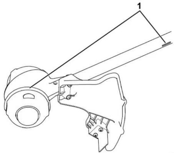
Align tongue the cavity handle on the handle
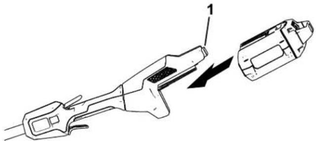
- Push the battery battery locks into
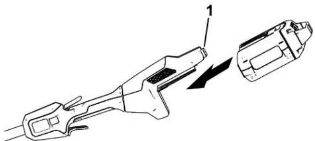
natural_image
Technical line drawing of a mechanical tool with an arrow indicating direction (no text or symbols)Figure 9
g330417
- Battery latch
- T o start the trimmer then squeeze the
- T o start the trimmer then squeeze the
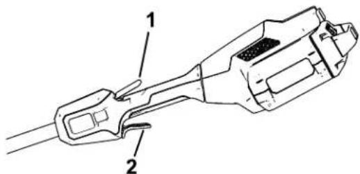
Figure 10
g330416
- Lockout trigger 2.
Shutting
Off
T o shut of f the trimmer
Whenever you are not transporting the trimmer remove the battery pack.
Removing from
the T rimmer
Press the battery latch battery pack and slide machine ( Figure 1 1 ).
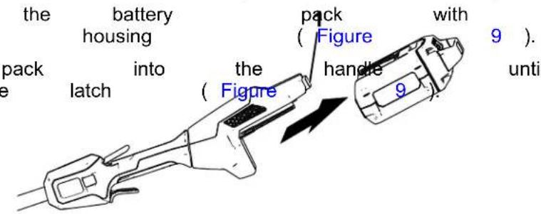
Figure 1 1
- Battery latch
the lockout ( Figure 10 ).
Charging the Battery Pack
5.
Refer
indicator
to the
the
light
following
on
the
Important: The battery pack is not fully charged when you purchase it. Before using the tool the first time, place and charge it until the battery pack is fully precautions.
Important:
temperatures
range;
refer
Charge
that
to
Spec
Note:
button
At any
on the
charge
(LED
。
to that Spe
 | the es sat |
| only batter ture ) lt* current |
[Non-Text]
urrer
- Ensure charger
that the
are clear
*Refer
to T roubleshooting
ventisformation. on the
any dust
battery
and the debris.
and
battery
lattery
between
important.
for short
periods
will
If the
battery
battery
fr
remove
(page
18 ) .
Figure
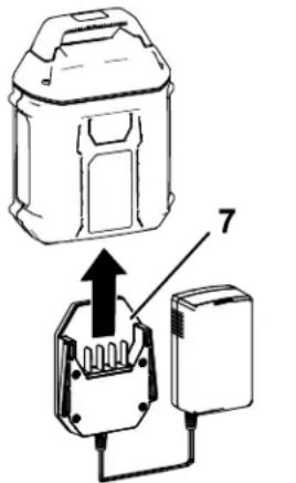
12
- Battery pack
cavity LED
charge)
- Battery
pack
venting
- Battery pack
te7minalsCharger
light
- Battery-charge-indicator 8.
Charger
button
indicators
(current
areas
6.
LED
indicator
venting
areas
- Line
up
the
cavity
[Non-Text]
in
the battery
pack
( Figur
the
charger
- Slide
the
battery
pack
into
the
charger
un
12 ).
- T o
remove
the
battery
pack,
slide
the
batte
out
of
charger
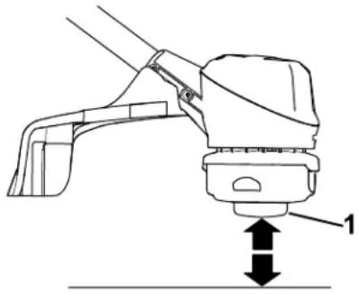
Advancing the Line Using the Bump Feed
- Run the tool at full throttle.
- T ap the bump button on the ground to advance
the line. The line advances each time the button is tapped. Do not hold the bump but on the ground.
Note: The line trimming cut-of f blade on grass deflector cuts the line to the correct
Note: If the line is worn too short, you may be able to advance the line by tapping it on ground. If so, release both triggers and ref Advancing the Line Manually (page 15).
natural_image
Technical line drawing of a mechanical device with a lever and base, showing no text or symbolsFigure 13
- Bump button
Advancing Manually
| Removethewhilethe | bumppullingline. | thebuttonon | batteryatthe | packthetrimmer | base | fromofline | thetheto | trimmerspoolmanually | retained |
the Line
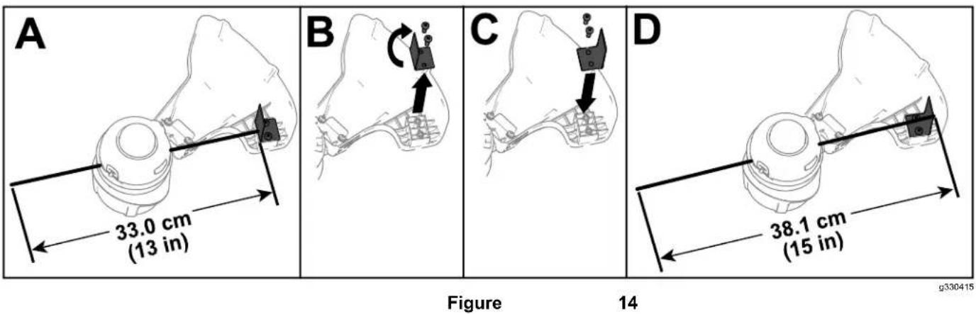
Adjusting the Cutting Swath
| The refer | trimmer to the | comes following | from instructions | the | factory | to | with adjust | a |
| 1. | Remove the provided | the swath Allen | blade wrench | from (B of Figure) | the bottom 14 | |||
| 2. | Once the Figure 14 ). | swath | blade is rotated, | install | ||||
Operating
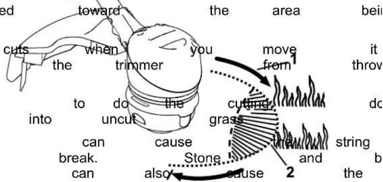
- Keep this is the best trimmer cutting area.
• The string trimmer to right. This prevents debris at you.
• Use the tip of the string force the string head - Wire and picket fences
wear rapidly and even
walls, curbs, and wood
to wear rapidly.
• A void damage fence trees tree posts. and bark,
T ips
Figure
s. wood Direction The moldings, string of rotation can siding, eas
Maintenance
Replacing
t
After each use of the trimmer, complete the following
- Remove the battery from the trimmer.
- Wipe the trimmer not hose the trimmer water.
CAUTION
The line sharp
Do not deflector
cutoff and can
use your shield
Important: ng: monofilament
88201), or purchase 88615 or pre-wound clean with a damp
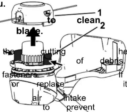
- Remove the batterypacksabherge clean any debris from the trimmer head.
- Press the tabs the trimmer head de ( Figure on the ). deflector
you.
hands and
the
head
f any
vents
the
0330429
- Wipe time or scrape is an clean accumulation
- Check and tighten all damaged or lost, repair
- Brush exhaust from debris on overheating. motor away from housing
Figure 16
- Cover and spool 2.
- Remove the spool any remaining string froi
- Cut 1 piece of 2 mm approximately 3 m (1
Important: Do not or type of string, as trimmer
- Bend the new string
the bend into the starter
the spool ( Figure 17
Note: Ensure that th in the slot. - W rap the 2 halves around the spool as
Note: Ensure that the clockwise around the bottom of the spool.
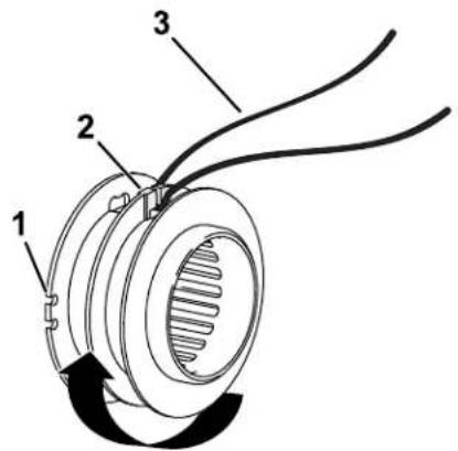
Figure 17
g330440
- Guide slot for string end 3. New string (once fully wound)
-
Center rim spool starter slot
-
Wind the string, leaving just enough from the spool to snap the ends into ( Figure 17 ).
-
Install the spool ends of the string as shown in Figure
natural_image
Technical line drawing of a mechanical assembly with labeled parts (no text or symbols present)Figure 18
g330442
- String exit holes
- Install the spool trimmer head, push into place.
Storage
Important: charger appropriate 12 ) . only Store in range; the temperatures re
Important: If you are the off-season, remove tool and charge the indicators turn green a fully charged or fully are ready to use the pack until the charger or all 4 LED the battery.
- Disconnect (i.e., remove battery pack) the product plug and check
- Do not store the tool extending act Clean the all foreign blade, material
•the When guide battery not slots in use, on the store of out of charge cover the tool, and route away from holes corrosive in the chemicals and de-icing
• T o reduce the risk of not store the battery
- Store the tool, battery in an enclosed clean,
Preparing for Recycling
Important: the battery Do not attempt battery
Upon pack
upon or
remo with to destroy remove
and

| Lithium-ion | battery | p |
| Call2Recycle | seal | car |
| participating | retailer | |
| facility in the | Call2Recycle | |
| and Canada | only). | T |
| retailer assembly facility | closest | |
| 1-800-822-8837 | tabs | or sh |
| If you cannot | locate | a |
| facility nearby | , or | if you |
| is not labeled | with | the |
| please contact | your | |
| information | on how | to |
| battery . If you are | are | located |
| and Canada, please | ||
| T oro distributor | . |
T roubleshooting
Perform only the steps described in these instructions. All further inspection, maintenance, and repair work must be performed by an authorized service problem yourself.
Always remove the battery from the tool when
| Problem | Possible | Cause | Correctiv |
| The tool does not continuously. | runThe or battery not is tool.The battery pack.The battery temperature4.There is moisture battery pack.The battery pack.There is another with the tool. | 1. run Renfoly installed and into the tool, making installed and latched.Remove not charge the battery and charge it.Move over the or battery where it is ridge. and between 5^ (41°F).Allowon the the lead battery dry .Coelectrical an prAborized | |
| The tool does not motor housing is | reate battery power pack gettinghot.The air vents | orRenfolyage capacity battery and fully charge are Cledocked.the air vents | the ship buthe the ag to bumhead shi buthe |
| The tool is producing or noise. | There excessive is debris or in the bump trimmer.The spool is not properly wound.and/or remove and wind the spool | vibrational they any grass debris headshield housing in the on | |
| The bump head | does The not trimmedvanceThe line is tangledhousing.There is debris or in the bump trimmer. | s1. outAdd of line more line2.Removin the buthe untangle the line.3. unClean they any grass debris headshield housing in the on | |
| The battery pack | loseThe battery parkly Move over the or battery appropriate temperature where it is ridge. and between 5^ (41°F)2.The trimmer is overloaded. | ||
| The battery charger | The is nd battery working. charger Unplug is over the bratter under the appropriate temperature place where range. temperature is and 40^ (104°F).2.The outlet that plugged into that does the Contad battery your charger repair not have outlet. power | ||
| The LED indicator charger is red. | Tight battery the batterger Unplug and/or the battery pack is over or undeh battery approportarger temperature range. to a place where temperature and 40^ (104°F). |
| Problem | Possible Cause Corrective | Action |
| The LED indicator charger is blinking | 1. Thereighs an error in the communication between the battery pack and the charger .2. The battery pack | 1. Remove the battery package battery charger , unplug charger from the secondsPlug the outlet again pack on the battery indicator light of still blinking red, again.If the LED the battery charger after 2 attempts, the battery pack facility .2. iProperly dispose a battery recycling |
Notes:
California Proposition 65 W arning Information
What is this warning?
Y ou may see a product for sale that has a warning label like

W ARNING:
Cancer
and
Reproductive
What is Prop 65?
| Prop California. reproductive inform | 65 the | applies It mandates harm. the public | to any The about | company that list, exposure | the which | operating Governor is updated to these | in of California annually chemicals. | selling maintain , includes | ||
| Prop the California chemicals | 65 does the product. government have | does not Moreover been | ban | the , has used | sale Prop clarified in everyday | of products 65 warning that | containing does a Prop products | not 65 for | these mean warning years | the |
| A has | Prop chosen | 65 warning to provide | means | that a warning | a based | company on | has its | either understanding | (1) | evalua |
Does this law apply everywhere?
| Prop limited retailers | 65 | warnings to restaurants, provide | are | required grocery Prop | under stores, 65 warnings | on | California hotels, their | law schools, websites | only and or in | The car |
How do the California warnings compare to
| Prop at the | 65 levels federal | standards that and | are far international | often lower | than | more federal standards. | stringent action | than limits. | federal For | and exempli |
Why don't all similar products carry the warning?
| Products | sold | in | California | require | Prop | 65 | labelling | while | ||
| A company making | similar | involved products | in | a | Prop may | 65 have | lawsuit no | such | reaching requirement. | a settlement |
| The enforcement | of | Prop | 65 | is | inconsistent. | |||||
| Companies product | does | may not | elect mean | not that | to the | provide product | warnings is | free | because of listed | chemi |
Why does T oro include this warning?
| T oro use, exposure, “no warnings, | has T oro | chosen provides as not risk it could | to all range, be sued | provide warnings listed | consumers in chemicals out by the State | with cases provide abundance of California | as based on exposure of caution, or by | much its knowledge |
Manual del operador
Desbrozadora de hilo 60V MAX de 33 cm (13") o 38 cm (15") con Flex - Force Power ™ Sy
natural_image
Technical line drawing of a mechanical device with articulated arms and a central hub (no text or symbols)
The Ground Truth image displays a single, solid horizontal line. According to Rule 2 (UNDERSCORE & LINE RULES), this is a stylistic or background line, not a placeholder underscore. Therefore, the OCR result must ignore it and output nothing or only meaningful text. The provided OCR content is "____", which consists of four underscores. This is an incorrect interpretation of the line as a placeholder, violating the rule that stylistic lines must be ignored. The OCR has hallucinated underscores where none should exist based on the GT's visual context. Hence, the OCR result is inconsistent with the Ground Truth.
observ
riesgo
144
- 3096
decal144
-3

139
- 5346
decal139
5

144
- 3084
decal144

-3084
144
- 3085
decal144

decal140 - 8475
140 - 8475
natural_image
Black rectangular object with four small square buttons and a circular gradient fill, no visible text or symbols.decal137 - 9461
137 - 9461
- Estado
de carga
de la
batería

decal139-5210
139 - 5210
natural_image
Mechanical diagram showing a clamping mechanism with a hook and connecting rod (no text or symbols)
natural_image
Mechanical diagram showing a rope knot being lifted by two clamps, with no visible text or symbolsFigura
4
3
natural_image
Diagram of a mechanical device with hanging weights and a dashed line indicating motion (no text or symbols)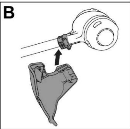
natural_image
Technical illustration of a mechanical assembly with a tool and component, no visible text or symbols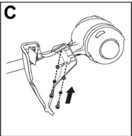
natural_image
Technical line drawing of a mechanical assembly with no visible text or symbolsFigura 5
g330190
El producto
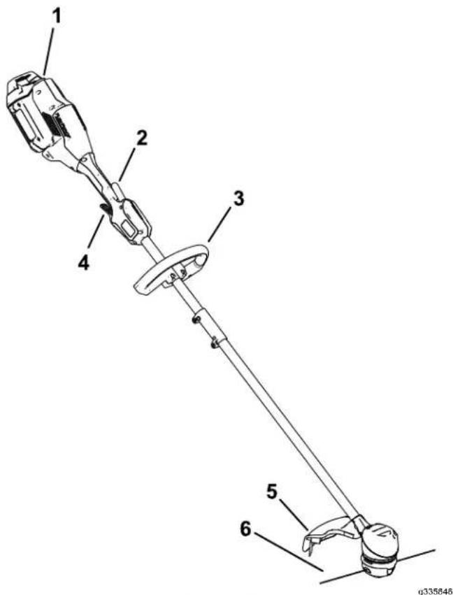
Figura 6
Figura 7
natural_image
Technical line drawing of a mechanical assembly with no visible text or symbolsFigura 8
1.
Zonas
de
ventilación
2.
Alinee
alojamiento
3.
Introduzca
batería
el
hueco
del
encaje
natural_image
Technical line drawing of a mechanical tool with an arrow indicating motion (no text or symbols)g330417
Figura 9
- Cierre
de
la
batería
4.
Para
gatillo
accionamiento
arrancar
de bloqueo,

Figura 10
1.
Gatillo
de
bloqueo
g330416
2.
Cómo desbrozadora
Para
apagar
la
desbrozadora,
Cuando
no
esté
utilizando
transportando
hacia
0
la
batería.
Cómo desbrozadora
Presione
desbrozadgra
el
cierre
de
la
de liberar la
batería,
y retire
( Figura
1 ).
m = 311
batería
con
la
lengüeta
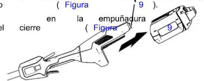
Figura 1 1
- Cierre
de
la
batería
g331067
( Figura
10
).
apriete
el
gatillo
Carga de la batería
natural_image
Technical line drawing of a mechanical device with labeled component 1 (no text or symbols beyond label)Figura
g330186
- Botón de avance
A vance
Retire
botón
carrete
avanzar
la batería
de avance
mientras
el hilo
manual
de la
situado
tira
manualmente.
desbrozadora,
en
del hilo
la
de
del
luego
base
la
del
desbrozadora
luego
retén
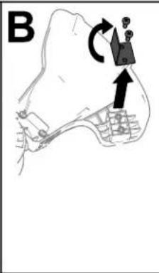
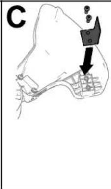

Figura 14
Consejos
Figura 17
g330440
natural_image
Technical line drawing of a mechanical assembly with a tool and component (no text or symbols)Figura 18
g330442
natural_image
Technical line drawing of a mechanical device with articulated arms and a central connector (no text or symbols)
natural_image
Black rectangular object with a circular indicator and four small square buttons (no text or symbols)decal137-9461
137 - 9461
- État de charge
de la batterie

decal139 - 5210
139 - 5210
natural_image
Technical line drawing of a mechanical component with hanging weights and a downward arrow indicating motion (no text or symbols)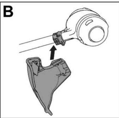
natural_image
Technical illustration of a mechanical assembly with a tool and component, no visible text or symbols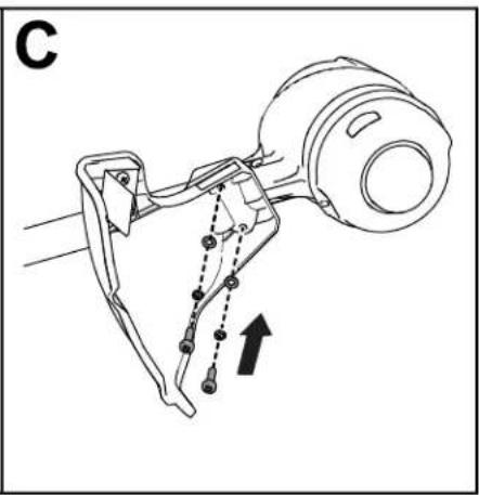
natural_image
Technical line drawing of a mechanical assembly with no visible text or symbolsFigure 5
g330190
Figure 6
Figure 7
natural_image
Technical line drawing of a mechanical assembly with no visible text or symbolsFigure 8
1.
Prises
d'air
de
la
débroussai
2.
Alignez
du corps
le
creux
de
la poignée
3.
Poussez
qu'elle
la
batterie
s'enclenche

natural_image
Technical line drawing of a mechanical tool with an arrow indicating direction (no text or symbols)Figure 9
1.
V
errou de
batterie
4.
Pour
appuyez
serrez
mettre
[Non-Text]
sur
la
gâchette
la
débroussailleuse
la
gâchette
广力云智慧零售收银系统
广力云智慧零售收银系统
de
marche

Figure
g330416
10
1.
Gâchette
de
verrouillage
12
natural_image
Technical line drawing of a mechanical device with no visible text or symbolsFigure 13
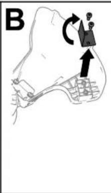
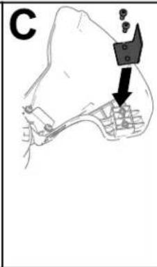
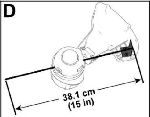
Figure 14
g330415
Conseils
Figure 17
g330440
natural_image
Technical line drawing of a mechanical assembly with labeled parts (no text or symbols present)Figure 18
g330442
- T rous
de sortie
du
- Installez
tête que
de les