JANA 2.0 - Radiator Sonnenkönig - Free user manual and instructions
Find the device manual for free JANA 2.0 Sonnenkönig in PDF.


User questions about JANA 2.0 Sonnenkönig
0 question about this device. Answer the ones you know or ask your own.
Ask a new question about this device
Download the instructions for your Radiator in PDF format for free! Find your manual JANA 2.0 - Sonnenkönig and take your electronic device back in hand. On this page are published all the documents necessary for the use of your device. JANA 2.0 by Sonnenkönig.
USER MANUAL JANA 2.0 Sonnenkönig
natural_image
Pure architectural floor plan lines without any text, numbers, or symbolsD
INDEX
text_image
300mm 250mm 600mmBild.1
4 Eigenschaften
text_image
Technical diagram showing exploded view of a battery pack with labeled components including screw, nut, and socket partsBild.2
text_image
760mm 466.6mm 600mm 197.5mmBild.3
6 Kontroll-Panel
D
text_image
1 2 3 4 E 10 11 5 6 7 8 9 M ⑦ WREMOTE KING SMARTE App
text_image
Welcome home AIR Devices Add DeviceD
Modus wählen
text_image
Weather icons and symbols for solar, moon, and moonlight with directional arrowsFestnetz 14 Cent/Minute
natural_image
Pure architectural floor plan lines without any text, numbers, or symbolsSOMMAIRE
text_image
300mm 250mm 600mmImage 1
4 Caractéristiques
text_image
Technical diagram showing exploded view of a mechanical assembly with labeled parts including screws, bolts, and fasteners.Image 2
text_image
760mm 466.6mm 600mm 197.5mmImage 3
text_image
1 2 3 4 E 10 11 5 6 7 8 9 MApp REMOTE KING SMARTE
text_image
Welcome home AR sensitivity 4.7 3.8 Cancel AND CloudActiver l'écran
F
text_image
Weather icons and symbols for solar, moon, and moonlight with directional arrows and tick marksModifications techniques
Festnetz 14 Cent/Minute
natural_image
Pure architectural floor plan lines without any text, numbers, or symbolsINDICE
text_image
Volume 1 Volume 2 Volume 1 Volume 3 400 cm 80 mm 50 mmFig.1
text_image
250mm 600mmtext_image
Technical diagram showing exploded view of a mechanical assembly with labeled parts including screws, fasteners, and fasteners.Fig.2
text_image
760mm 466.6mm 600mm 197.5mmFig.3
App REMOTE KING SMARTE
text_image
Welcome home AIR SWITCH 4.7 3.0 1 0 2 Send AAP Devicestext_image
Diagram showing directional symbols and numerical values, including arrows and circles with labels -1, -2, 0, 1, 2, 3, 4, 5, 6, 7, 8, 9.natural_image
Pure architectural floor plan lines without any text, numbers, or symbolsINDEX
1 Safety Information 38
2 Specification.... 39
3 Where to install the heater.... 39
4 Description of the equipment 40
5 Installation....41
6 Control panel 42
7 Maintenance 45
8 Garantie / élimination / modifications techniques.... 45
Information requirements.... 59
1 Safety Information
GB
Please read before first commissioning the safety instructions carefully and observe the safety instructions to prevent damage due to misuse, improper operation, and improper environmental conditions to be avoided. Keep these for later reference. Please make sure to place the device on a suitable and waterproof surfaces, so that spilled liquids can not cause harm.
Check the device after removing the packaging for damage. Do not put the unit in case of suspected corruption in operation and consult a specialist. The recyclable packaging material must not be stored or disposed accessible for young children, but must be disposed of properly.
This appliance is only for the purpose for which it was explicitly developed. Any other use is regarded as improper and therefore dangerous. The supplier is not liable for damage to persons and / or property damage due to an improper or incorrect use.
This appliance can be used by children aged from 8 years and above and persons with reduced physical, sensory or mental capabilities or lack of experience and knowledge if they have been given supervision or instruction concerning use of the appliance in a safe way and understand the hazards involved. Children shall not play with the appliance. Cleaning and user maintenance shall not be made by children without supervision.
Please make sure to place the device on a suitable and waterproof surfaces, so that spilled liquids can not cause harm.
Repairs to electrical appliances must only be carried out by trained personnel only. Improperly performed repairs and alterations to the equipment can have dangerous consequences for the user according to what the warranty will be rejected.
- This appliance is not intended for use by persons (including children) with reduced physical, sensory or mental capabilities, or lack of experience and knowledge, unless they have been given supervision or instruction concerning use of the appliance by a person responsible for their safety. Children should be supervised to ensure that they do not play with the appliance.
- Means for disconnection must be incorporated in the fixed wiring in accordance with the wiring rules.
- If the supply cord is damaged, it must be replaced by the manufacturer, its service agent or similarly qualified persons in order to avoid a hazard.
- This product was designed to be installed inside and is intended for indoor use only. Please do not use the product for any other purpose.
-
The electrical installation must be carried out by a qualified electrician in accordance with the local regulations.
-
The heater is to be installed in a way that switches and other controls cannot be touched by a person in the bath or shower.
- For your safety, this heater is fitted with a thermal cut-out. In the event that the product overheats for some reasons, the cut-out prevents excessive temperatures on the product by cutting the power to the heater.
GB
2 Specifications
3 Where to install the heater
- This heater is designed to be installed and used indoors only.
- Do not locate the heater below a fixed socket outlet or connection box.
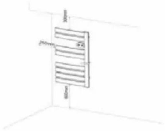
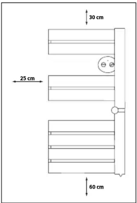
- Comply with the minimum clearance distances as indicated in fig. 1.
- In humid areas such as bathrooms and kitchens, the connection box must be installed at least 25 cm above the floor.
- Do not install the heater in the following locations:
- In a draught likely to affect the control setting
- Under a fixed mains power socket
- In the bathroom area indicated as volume 1 (see fig. 1)
- In the area indicated as volume 2 if the controls can be operated by a person using the shower or bath (see fig.1)
text_image
30 cm 25 cm 60 cm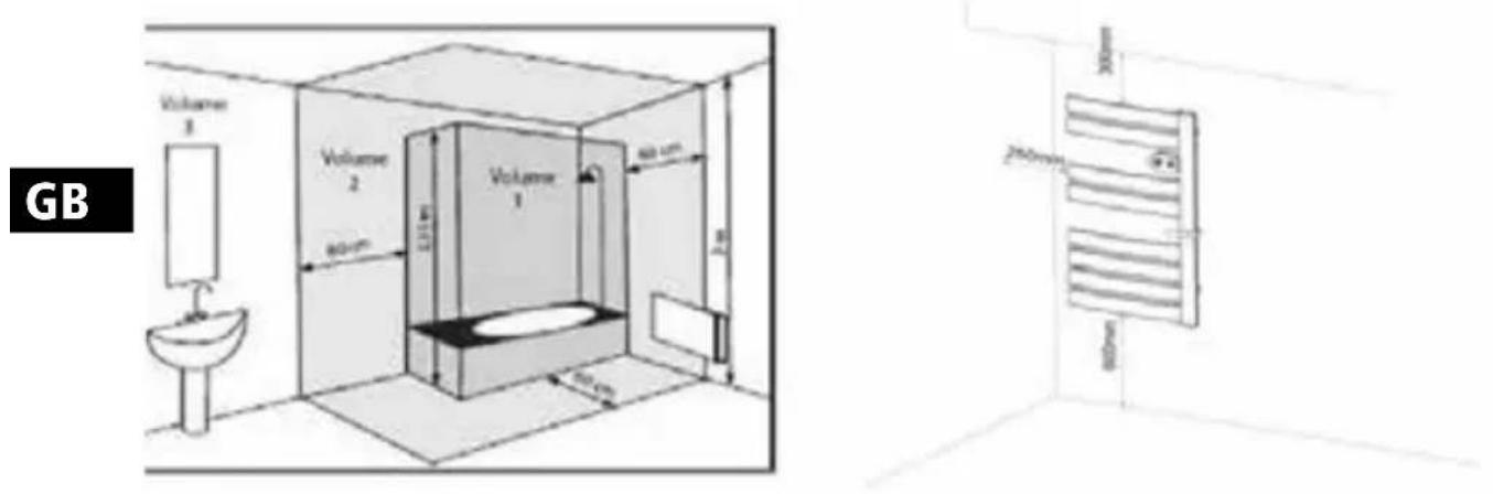
Fig.1
4 Description of the equipment
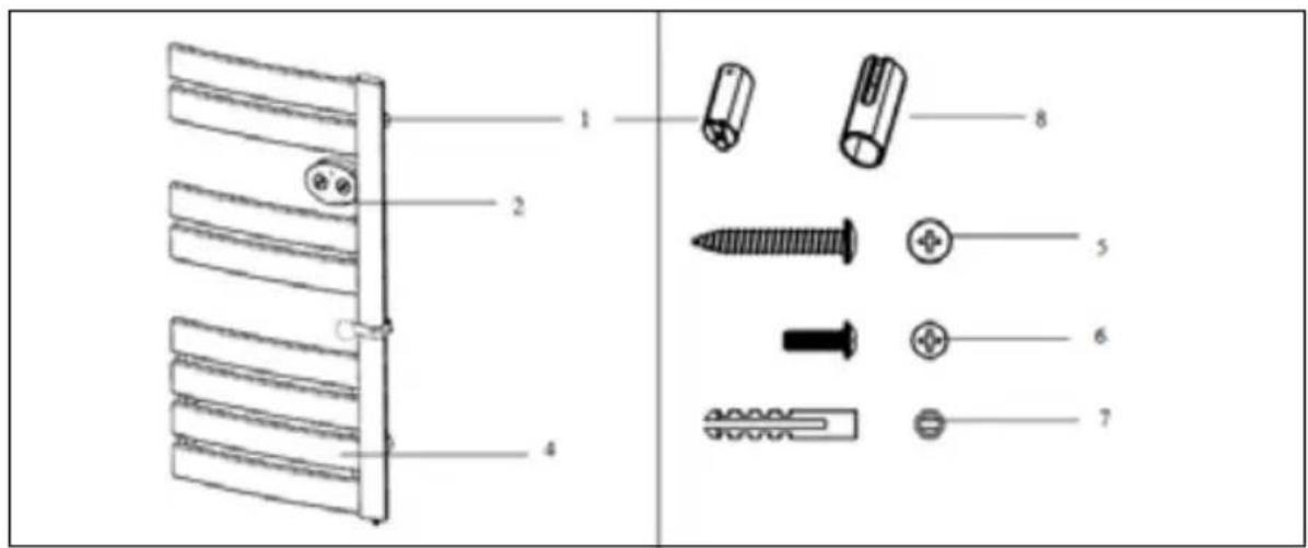
text_image
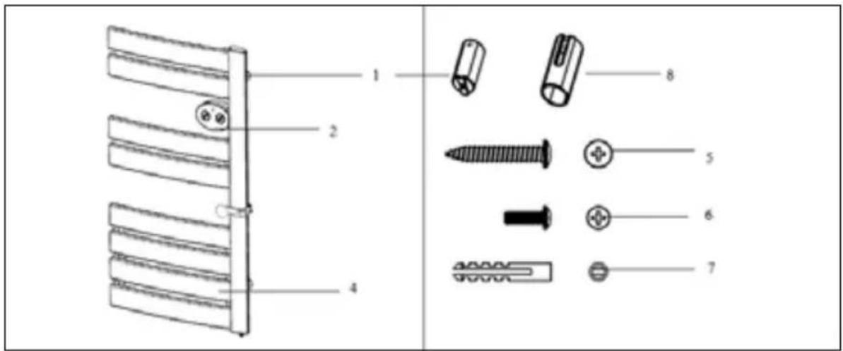
Technical diagram showing exploded view of a mechanical assembly with labeled parts including screws, fasteners, and fasteners.Fig.2
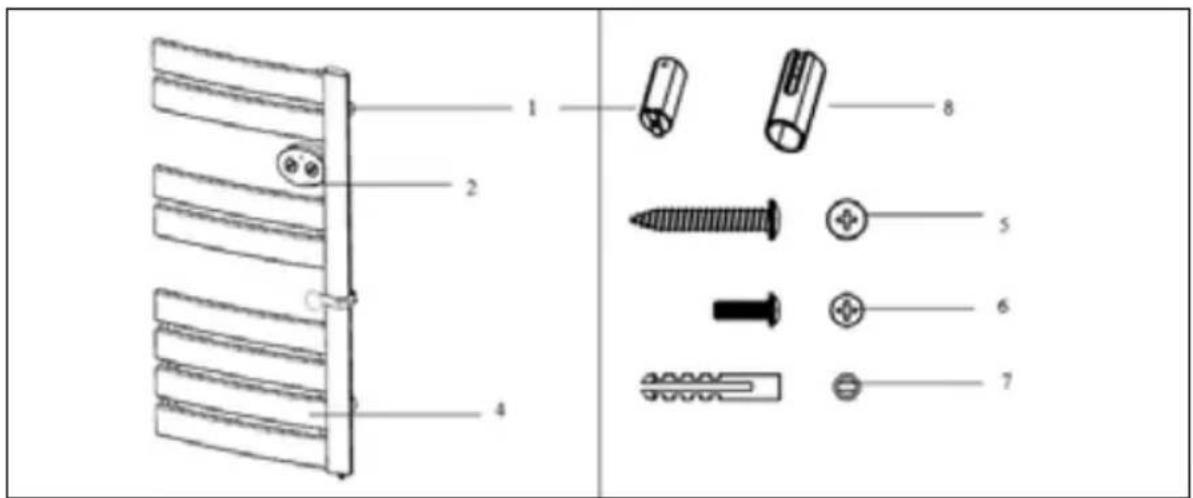
- Fastener covers: 3 pcs
- Control display
- Heating panel
*5. Screw 3.9x30mm: 3 pcs
6. Screw M4x10mm: 3 pcs
*7. Screw ∅10x40mm: 3 pcs
8. Wall mounting covers: 3 pcs
*These screws are not suitable for the following walls: Wood, brick and plaster. Please use the appropriate screws for your wall.
5 Installation
Step 1
Fix the fastener covers 1 (see fig. 2) on the product;
Step 2
Fix the supplied wall mounting covers 8 (see fig. 2) onto the wall using screws 5 and screws 7 (see fig. 2), according to the distance instructions in fig. 3;
Step 3
Place the fastener covers 1 (see fig. 2) into the wall mounting covers 8 (see fig. 2) on the wall;
Step 4
Use screws 6 (see fig. 2) to fix the fastener covers 1 (see fig. 2) and the wall mounting covers 8 (see fig. 2) together.
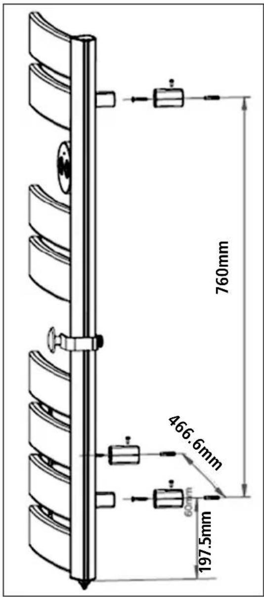
text_image
760mm 466.6mm 600mm 197.5mmFig.3
GB
6 Control Panel
GB
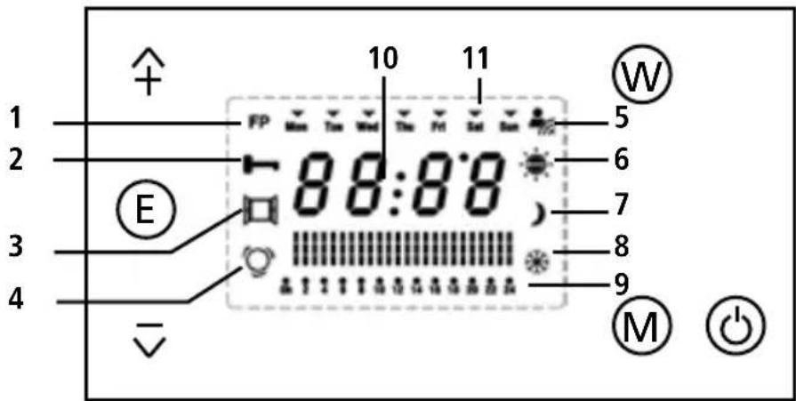
text_image
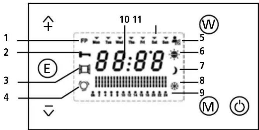
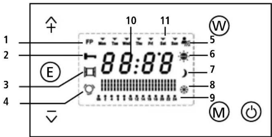
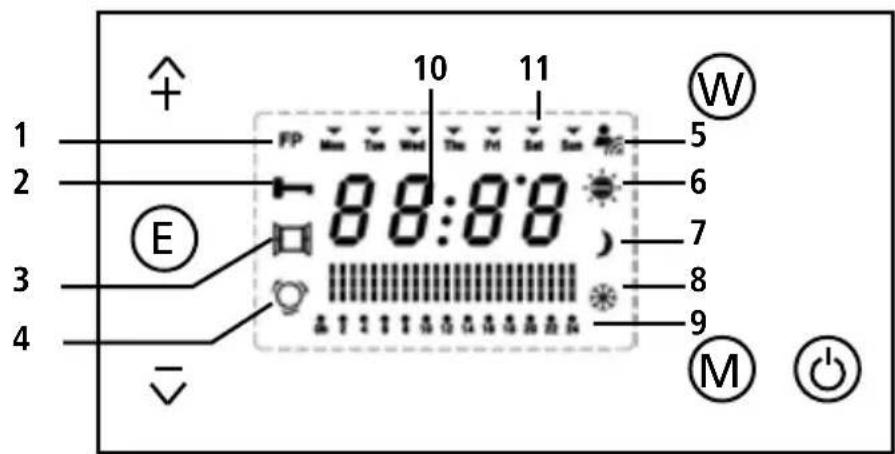
1 2 3 4 E 10 11 FP 5 88:88 6 7 8 9 M- FP (wire connection)
- locks
- Open window
- Weekly programme
- Wifi
-
Comfort mode
-
Eco mode
- Anti frost mode (temp. at 7°C)
- Hourly setting
- Time and temperature
- Weekly days
REMOTE KING SMARTE App
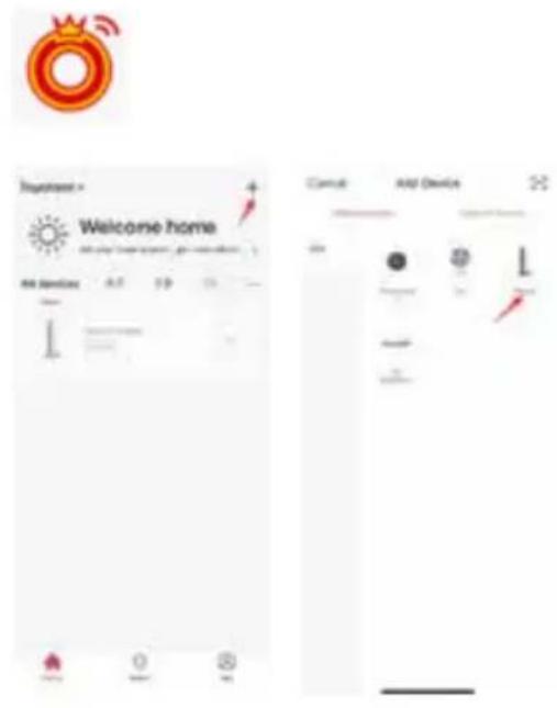
Connect to the REMOTE KING SMARTE app via WIFI.
Connect WIFI to the app
Long press the Mode button on the radiator until the Wifi sign flashes slowly. Log in to the app and connect a new device. Follow the instructions on the smartphone.
Now operate the unit via the smart-phone.
text_image
Welcome home Add Devices Control Add DeviceActivate display
Press the ON/OFF button on the control panel. The heater goes into anti-freeze mode, the LCD screen shows 7.0°C and .
Select mode
GB
When the heater is in operating mode, press the „MODE“ button to select different operating modes. There are 6 operating modes:

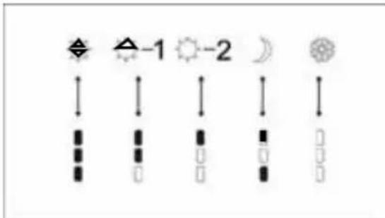
Comfort mode: The user can set the comfort temperature by pressing „+“ and „-“ on the keypad; after selecting the temperature for your comfort mode, stop pressing and wait for 5 seconds, the „°C“ on the screen will flash 5 times, the temperature is set. Press „+“ or „-“ for more than 1 second to set the tem- quickly. The temperature range is 5°C \~ 35°C.

Comfort mode minus 1^ C: The user cannot adjust the temperature. The heater lowers the temperature by 1^ C from the comfort temperature set in comfort mode. For example, if you set 19^ C as the comfort mode, the temperature in comfort mode minus 1^ C, is 18^ C.
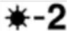
Comfort mode minus 2^ C: The user cannot set the temperature. The heater lowers the temperature by 2^ C from the comfort temperature set in comfort mode. For example, if you have set 19^ C as the comfort mode, the temperature in comfort mode minus 2^ C is 17^ C.

ECO mode: The user cannot adjust the temperature. The heater lowers the temperature by 3.5^ C from the comfort temperature set in comfort mode. For example, if you have set 19^ C as the comfort temperature in ECO mode is -3.5^ C, i.e. 15.5^ C.
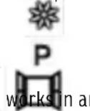
Anti-Frost Mode: The temperature is 7^ C, user cannot adjust the temperature.
Programme mode: User can set the working mode in the current time and in the future for one week. Open window: If the heater detects that the room temperature drops by 4°C within 30 minutes, the heater anti-frost mode.
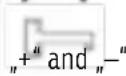
Keypad Lock Function: The keypad can be locked to prevent tampering by pressing and holding down the keys for 3 secondd. This function can be reversed by repeating the above process.
P1 From 0 to 6: Eco mode From 6 to 9: Comfort mode From 9 to 17: Eco mode From 17 to 23: Comfort mode From 23 to 6: Eco mode
P2 From 0 to 6: Eco mode From 6 to 9: Comfort mode From 9 to 12: Eco mode From 12 to 13:30: Comfort mode From 13:30 to 17: Eco mode From 17 to 23: Comfort mode From 23 to 6: Eco mode
Selection of the week
After you have selected the programme mode, you can press the „P“ key on the control panel to set the week from Monday to Sunday. Press „+“ or „-“ to select another day. An ▼ appears on the day you have selected. Press „P“ again to confirm the selection.
Time setting
If you press „P“ again to confirm the selection of the day, the time is set automatically. The „Hour“ position flashes, you can set the hour by pressing „+“ and „-“. Each time is adjusted by one hour. Press „P“ again to confirm the hour, at the same time the automatic setting of the minute is activated. The „Minute“ position flashes, you can push through and set the minutes with „+“ and „-“. Each time is adjusted by one minute.
Setting the working mode for each hour
After finishing the time setting, press the „P“ key again to set a weekly or 24-hour programme. Press the „Mode“ key to select different modes, press the „+“ and „-“ keys to select different hours. Press the „Mode“ button for three seconds to access the „P1“, „P2“, „P3“ and „P4“ modes and press the „+“ and „-“ buttons to
select. Each symbol corresponds to the respective working mode as shown below:
When you have finished selecting the working mode, press "P" to confirm and at the same time the next hour mode is set.
After setting the working mode of each hour for one day, you can press „P“ again to confirm and set the working mode for the second and third day.... When you have finished setting the working mode for a week, press „P“ again to return to the current working mode and the heater will start working according to the programme you have set.
text_image
Weather and weather icons with symbols for moon, sun, moon, and moon with directional arrowsOpen window detection
Continuously pressing the "+" "-" keys at the same time for 3 seconds, open window function ■will be activated. If the heater detected the room temperature drops 4^ within 30 minutes, then the heater will work under Anti Frost mode.
The heater will recover working under previous working program automatically if the temperature recovers 2°C, or by continuously pressing the "+" "-" keys at the same time for 3 seconds again.
7 Maintenance
- Before you clean the appliance, switch the heater off and wait until the heater has cooled down.
- Use a damp cloth to wipe off the housing.
- Do not use water, detergents, abrasive cleaning liquids or chemical agents (alcohol, gasoline, etc.) to clean the appliance.
8 Warranty / Disposal / Technical change
Warranty
All products are checked from our company before the delivery. In case that there is a lack on your product, please contact the vendor. Please bring your proof of purchase for guarantees. The guarantee period is 24 months from date of purchase.
Disposal
Please remove the heater properly. You can bring the product to any specialist dealer fort he removal.
Technical changes
Technical changes in technique and design are possible.
Please save the packaging materials of the unit.
CE declaration of Conformity
This device complies with the following standards
EN 60335-1:2012+A11:2014+A13:2017+A1:2019+A14:2019+A2:2019+A15:2021
EN 60335-2-30:2009+A11:2012+A1:2020+A12:2020+A2:2022+A13:2022
EN IEC 60335-2-43:2020+A11:2020
EN 62233:2008
EN IEC 55014-1:2021
EN 61000-3-3:2013+A1:2019+A2:2021
EN IEC 61000-3-2:2019+A1:2021
EN IEC 55014-2:2021
Firma
Armin Schmid
Festnetz 14 Cent/Minute
natural_image
Pure architectural floor plan lines without any text, numbers, or symbolsNL
INHOUDSOPGAVE
text_image
300mm 250mm 4.4 400mmFig.1
NL
text_image
Technical diagram of a screw assembly with labeled parts including screws, fasteners, and fastenersFig.2
text_image
760mm 466.6mm 60mm 197.5mmFig.3
6 Bedieningspaneel
text_image
1 2 3 4 E 10 11 5 6 7 8 9 Mtext_image
Welcome home AI Services 0.7 1.8 2.5 Current AI DevioDisplay activeren
text_image
Weather and weather icons including moon, sun, and partly cloudy symbols with directional arrowsThis device complies with the following standards
EN 60335-1:2012+A11:2014+A13:2017+A1:2019+A14:2019+A2:2019+A15:2021
EN 60335-2-30:2009+A11:2012+A1:2020+A12:2020+A2:2022+A13:2022
EN IEC 60335-2-43:2020+A11:2020
EN 62233:2008
EN IEC 55014-1:2021
EN 61000-3-3:2013+A1:2019+A2:2021
EN IEC 61000-3-2:2019+A1:2021
EN IEC 55014-2:2021
Bedrijf
Armin Schmid
Olensbachstrasse 9-15
CH-9631 Ulisbach
Tel. Int. +41 71 987 60 60
Nat. 0848870850
| Item | Symbol | Value | Unit | Item | Value |
| Heat output Type of heat input, for electric storage | |||||
| Nominal heat output | P nom | 0.6 | kW | Storage local space heaters only (select one) | |
| Minimum heat output (indicative) | P min | N/A | kW | Manual heat charge control, with integrated No thermostat | no |
| Maximum continuous heat output | P max,c | 0.6 | kW | Manual heat charge control with room and/or outdoor temperature feedback | no |
| Auxiliary electricity consumption | Electronic heat charge control with room and/or outdoor temperature feedback | no | |||
| At nominal heat output | el max 0 | kW Type of heat output/room temperature control (select one) | |||
| At minimum heat output | el min | 0 | kW | Single stage heat outp ut and no room temperature control | no |
| In standby mode | el SB | 0.00046 | kW | Two or more manual stages, no room temperature control | no |
| With mechanic thermostat room temperature control | no | ||||
| With electronic room temperature control | no | ||||
| Electronic room temperature control plus day timer | no | ||||
| lectronic room temperature control plus week timer | yes | ||||
| Other control options (multiple selections possible) | |||||
| Room temperature control, with presence detection | no | ||||
| Room temperature control, with open window detection | yes | ||||
| With distance control option | yes | ||||
| With adaptive start control | no | ||||
| With working time limitation | no | ||||
| With black bulb sensor | no | ||||