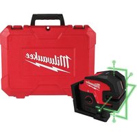
M12 3624-20 - Laser level MILWAUKEE - Free user manual and instructions
Find the device manual for free M12 3624-20 MILWAUKEE in PDF.


| Brand | Milwaukee |
| Model | M12 3624-20 |
| Category | Laser level |
| Product Type | Green 4-point and cross-line laser |
| Voltage | 12 V DC |
| Battery Type | M12™ |
| Charger Type | M12™ |
| Laser Class | Class 2 |
| Maximum Line Power | ≤ 7 mW |
| Maximum Point Power | ≤ 1 mW |
| Wavelength | 510 to 530 nm |
| Working Range | 38 m (125') |
| Range with Detector | 50 m (165') |
| Accuracy | ±3 mm at 10 m (±1/8\" at 33') |
| Self-Leveling Time | < 3 seconds |
| Self-Leveling Range | ±4° |
| Tripod Mount | 1/4\"-20, 5/8\"-11 |
| Protection Rating | IP54 |
| Operating Temperature | -20°C to 40°C (-4°F to 104°F) |
| Storage Temperature | -20°C to 49°C |
| Main Functions | Automatic leveling, energy-saving mode, 3 laser modes (horizontal line, vertical line, perpendicular), plumb points up/down |
| Maintenance and Cleaning | Clean with a damp cloth and mild soap; do not use solvents; blow off lenses with compressed air |
| Safety | Do not look directly into the beam; Class 2 laser; turn off and lock pendulum after use |
| Spare Parts and Repairability | Have repairs done by an authorized Milwaukee service center; do not disassemble yourself |
| Warranty | 5 years (subject to exceptions) |
Frequently Asked Questions - M12 3624-20 MILWAUKEE
User questions about M12 3624-20 MILWAUKEE
0 question about this device. Answer the ones you know or ask your own.
Ask a new question about this device
Download the instructions for your Laser level in PDF format for free! Find your manual M12 3624-20 - MILWAUKEE and take your electronic device back in hand. On this page are published all the documents necessary for the use of your device. M12 3624-20 by MILWAUKEE.
USER MANUAL M12 3624-20 MILWAUKEE
Read all safety warnings, instructions, illustrations and specifica
tions provided with this power tool. Failure to follow all instructions listed below may result in electric shock, fire and/or serious injury. Save all warnings and instructions for future reference. The term "power tool" in the warnings refers to your mains-operated (cored) power tool or battery-operated (cordless) power tool.
LASER SAFETY
WARNING
The device produces visible laser beams, which are emitted from the
tool.
- This device complies with 21 CFR 1040.10 and 1040.11 except for conformance with IEC 60825-1 Ed. 3., as described in Laser Notice No. 56, dated May 8, 2019.
Laser light - Do not stare into beam or vie directly with optical instruments. Do not point laser light at others. Laser light can cause eye damage.
WORK AREA SAFETY
- Keep work area clean and well lit. Cluttered or dark areas invite accidents.
- Do not operate power tools in explosive atmospheres, such as in the presence of flammable liquids, gases or dust. Power tools create sparks which may ignite the dust or fumes.
- Keep children and bystanders away while operating a power tool. Distractions can cause you to lose control.
PERSONAL SAFETY
- Do not allow persons unfamiliar with the tool, these safety instructions, and the tool's operator's manual to operate the tool. This tool can be dangerous in the hands of untrained users.
- Do not overreach. Keep proper footing and balance at all times. This enables better control of the tool in unexpected situations.
BATTERY TOOL USE AND CARE
- Recharge only with the charger specified by the manufacturer. A charger that is suitable for one type of battery pack may create a risk of fire when used with another battery pack.
- Use power tools only with specifically designated battery packs. Use of any other battery packs may create a risk of injury and fire.
- When battery pack is not in use, keep it away from other metal objects, like paper clips, coins, keys, nails, screws or other small metal objects, that can make a connection from one terminal to another. Shorting the battery terminals together may cause burns or a fire.
- Under abusive conditions, liquid may be ejected from the battery; avoid contact. If contact accidentally occurs, flush with water. If liquid contacts eyes, additionally seek medical help. Liquid ejected from the battery may cause irritation or burns.
-
Do not use a battery pack or tool that is damaged or modified. Damaged or modified batteries may exhibit unpredictable behavior resulting in fire, explosion or risk of injury.
-
Do not expose a battery pack or tool to fire or excessive temperature. Exposure to fire or temperature above 265°F (130°C) may cause explosion.
- Follow all charging instructions and do not charge the battery pack or tool outside the temperature range specified in the instructions. Charging improperly or at temperatures outside the specified range may damage the battery and increase the risk of fire.
SPECIFIC SAFETY RULES FOR LASER LEVELS
- Watch out for erroneous results if the tool is defective or if it has been dropped, misused or modified.
- Do not dispose of tool or batteries together with household waste material! Tool and batteries that have reached the end of their life must be collected separately and returned to an environmentally compatible recycling facility.
- Ensure tool magnets are securely mounted to a metal surface. Magnet strength may not hold von thin metal surfaces, causing the tool to fall.
- Always use common sense and be cautious when using tools. It is not possible to anticipate every situation that could result in a dangerous outcome. Do not use this tool if you do not understand these operating instructions or you feel the work is beyond your capability; contact MILWAUKEE Tool or a trained professional for additional information or training.
- Maintain labels and nameplates. These carry important information. If unreadable or missing, contact MILWAUKEE for a free replacement.
- The device conforms to the most stringent requirements of the relevant Electromagnetic Compatibility (EMC) Standards and Regulations. Yet, the possibility of causing interference in other devices cannot be totally excluded.
- CAUTION Use of controls or adjustments or performance of procedures other than those specified herein may result in hazardous radiation exposure.
- Be sure to power off instrument after use. When instrument will not be used for a long period, place it in storage after removing batteries.
Federal Communications Commission AWARNING Changes or modifications to this unit not expressly approved by the party responsible for compliance could void the user's authority to operate the equipment. This equipment has been tested and found to comply with the limits for a Class B digital device, pursuant to Part 15 of the FCC Rules. These limits are designed to provide reasonable protection against harmful interference in a residential installation. This equipment generates, uses and can radiate radio frequency energy and, if not installed and used in accordance with the instructions, may cause harmful interference to radio communications.
However, there is no guarantee that interference will not occur in a particular installation. If this equipment does cause harmful interference to radio or television reception, which can be determined by turning the equipment off and on, the user is encouraged to try to correct the interference by one or more of the following measures:
- Reorient or relocate the receiving antenna.
- Increase the separation between the equipment and receiver.
- Consult the dealer or an experienced radio/TV technician for help.
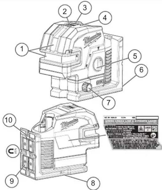
- Laser aperture
2.Mode button - Fuel gauge
- Power save indicator
- On/Off dial
-
Pivot Bracket
-
Micro adjust
- Threaded tripod attachment
- Magnets
- Nail/Screw hole
SPECIFICATIONS
Cat. No. 3624-20
Volts. 12 DC
Battery Type .M12TM
Charger Type. M12TM
Laser.Class 2
Lines Max Power PAVG 7 mW
Points Max Power. PAVG≤ 1mW
Pulse Frequency. 10 KHz
Pulse Duration Normal Mode. Tp ≤ 80 µs
Pulse Duration Power Save. Tp ≤ 50 µs
Wavelength. 510-530 nm
Lines Beam Divergence 1 rad
Points Beam Divergence 0.5 mrad
Storage Temp -4°F to 120°F
Working Range. 125
Range with Detector 165
Accuracy 1/8" @ 33
Settle Time < 3 Seconds
Tripod Mount 1/4"-20, 5/8"-11
Ingress Protection.. IP54
Drop Rating 1 m
Leveling .........Auto ± 4 side to side, front to back
Recommended Ambient
Operating Temperature. -4°F to 104°F
Volts V

Direct Current
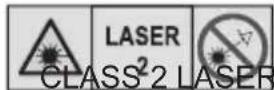
LASER RADIATION DO NOT STARE INTO BEAM PRODUCT


Read operator's manual
ASSEMBLY
WARNING Recharge only with the charger specified for the battery. For specific charging instructions, read the operator's manual supplied with your charger and battery.
Removing/Inserting the Battery
To remove the battery, push in the release buttons and pull the battery pack away from the tool.
AWARNING Always remove the battery pack anytime the tool is not in use.
To insert the battery, slide the pack into the body of the tool. Make sure it latches securely into place.
WARNING Only use accessories specifically recommended for this tool. Others may be hazardous.
Power Save
Use power save mode to extend the battery run time. Power save mode is indicated by dimmed laser beams and the Power Save Indicator pulsing. Visual range is decreased in power save mode. Power Save Indicator will change from pulsing to solid Green when turned OFF. The tool will automatically switch to power save mode if less than 7% of battery charge remains.
Fuel Gauge
To determine the amount of charge left in the battery, turn the tool ON. When less than 7% of charge is left, 1 light on the fuel gauge will flash continuously. To signal the end of charge, will flash 4 times and then the tool will shut off. Charge the battery pack. If the battery becomes too hot, the fuel gauge lights will flash. Allow the battery to cool down.
AWARNING To reduce the risk of injury or damage, securely mount/attach the laser before starting an operation. Injury/damage may occur if the laser falls.
Mounting/Adjusting the Laser Level
The pivot bracket can be used to mount the laser level in multiple ways:
- Use the embedded magnets to secure the laser level to steel studs, steel beams, etc.
- Use the keyhole slot to hang the laser level on the wall with a nail or screw.
- Set the laser level on a flat surface.
- Position the laser and/or wall mount on a stable surface.
- Use the 1/4"-20 or 5/8"-11 threaded insert to mount on a tripod.
-Once the level is mounted, use the micro adjustment knobs to fine tune the laser line.
WARNING
look directly
To reduce the risk of injury or temporary effects on vision, do not into the laser when it is on.
CAUTION
Use of controls or adjustments or the performance of procedures other than specified herein may result in hazardous exposure.
NOTICE Perform the Accuracy Field Check procedure immediately upon unboxing of each new Laser Level and before exposure to jobsite conditions. See "Accuracy Field Check" for information.
Turning On/Off
To turn on the laser and unlock the pendulum, rotate the On/Off dial to the desired position. The remaining battery life will be displayed. WARNING! Do not look directly into laser apertures. Horizontal level line and left/right plumb points will immediately be emitted from aperture in the laser housing.
ON
Turns ON the laser and unlocks the pendulum to enable self-leveling.
ON
Turns ON the laser but does not unlock the pendulum (self leveling is disabled). The laser lines will flash once every 8 seconds to indicate that the projected lines and dots are not level or plumb.
NOTICE: The ON mode disables self-leveling and therefore is not intended for projecting a level or plumb lines/points.
OFF
Turns OFF the laser and locks the pendulum. When not in use, turn off the tool and store the Laser Level in the protective carrying case
Use the MODE button to cycle through the three laser modes:
Horizontal Level Line & Horizontal Points
Vertical Plumb Line & Plumb Points
- Perpendicular Level, Plumb Points and Horizontal Points
Using the Laser Level
- For best results, place the tool on a work surface that is:
sturdy
- level (within 4 degrees of true level)
- free of vibrations
90° to the work area
-
Turn on the tool.
-
The tool will self-level when placed on surfaces within 4 degrees of true level when dial is unlocked and on.
- The tool is ready once the emitted lines are continuous and no longer moving on the work surface.
- If the tool cannot achieve a level state (i.e., the work surface is >4 degrees off true level), the laser beams will flash rapidly (3 flashes per second). Relocate or adjust the work surface.
Troubleshooting
If the tool does not turn on:
- Ensure battery is installed properly. Fuel gauge should indicate remaining charge when correctly installed.
- Ensure battery is charged.
- Ensure the tool's internal temperature is within specified operating ranges. If stored in excessive heat or cold, allow at least 2 hours to acclimate to ambient temperature before turning on the tool. If problem persists, please contact a MILWAUKEE service facility for support.
ACCURACY FIELD CHECK
NOTICE Perform the Accuracy Field Check procedure immediately upon unboxing of each new Laser Level and before exposure to jobsite conditions. See "Accuracy Field Check" for information. Should any deviation from listed product accuracy be found, please contact a MILWAUKEE service facility. Failure to do so could result in rejection of warranty claim.
Influences on Accuracy
Ambient temperature gradients can impact laser accuracy. For accurate and repeatable results, the following procedure should be conducted with the laser elevated off the ground and placed in the center of the working area.
Abusive treatment of the Laser Level, such as excessive impacts from drop, can also lead to deviations in product accuracy.
Therefore, it is recommended to conduct the Field Check procedure after any impact or before completing any critical jobs.
Horizontal Height Accuracy
eA free measuring distance of approximately 66' on a firm surface between two walls or structures A and B is required for this check.
It is also suggested to mount the Laser Level to a Tripod for easy adjustment.
- Securely mount the tool within 1' of wall A.
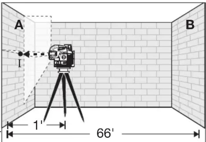
- Turn the tool to ON and to Perpendicular Level, Plumb Points, & Horizontal Points mode.
- Direct the front laser beam against the nearest wall A and allow to self-level. Mark the center of the laser cross on the wall (point I).
- Rotate the tool 180° without changing the height, allow it to self-level, and mark the center of the laser cross on the opposite wall B (point II).
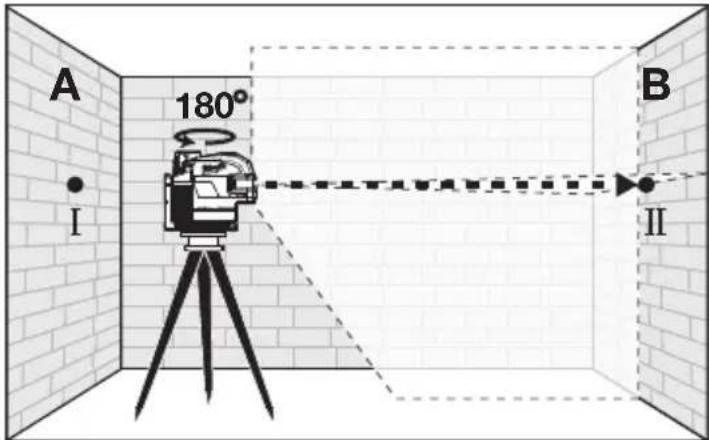
- Move the tool within 1 of wall B. Allow the laser to self level. Align the laser cross in the general direction of point II on wall B.
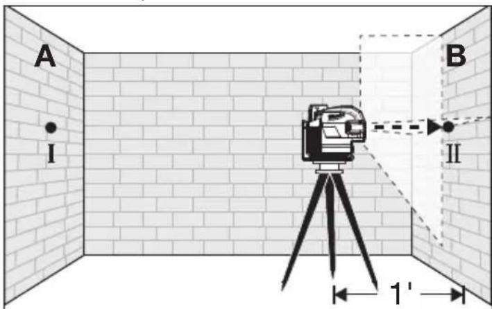
-
Adjust the height of the tool (using the tripod or by adding shims, if required) to align the laser cross directly onto point II on wall B. Allow the tool to self-level.
-
Rotate the tool 180° without changing the height, allow it to self-level, and mark the center of the laser cross on wall A (point III). Point III should be aligned as vertically above or below point I on wall A as possible.

- The distance between points I and III on wall A is the height deviation (d) of the tool. This distance should not exceed 1/8'' (max.) at 33' ( 1/2'' at 132' ) For the Measuring distance of 2 × 66' = 132' , the maximum allowable deviation (d) is: 132' × ± 1/8'' ÷ 33' = ± 1/2'' .
Horizontal Leveling Accuracy
A free measuring space of approximately 33x33 on a firm surface between two walls or structures A and B is required for the check.
It is also suggested to mount the Laser Level to a Tripod for easy adjustment.
Securely mount the tool on one side of the room and centered between walls A and B. Direct the laser lines toward the other side of the room such that the horizontal line appears on both walls A and B. Allow the laser to Self-Level.
- Turn the tool to ON and to Horizontal Level Line mode and Horizontal Points mode.
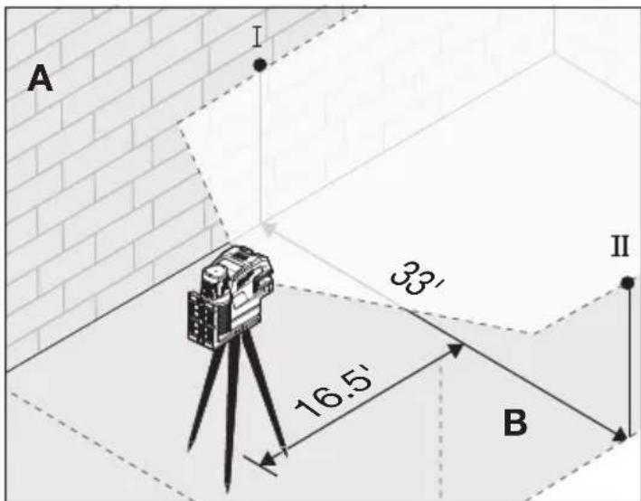
- Mark the center of the plumb point on the wall (point I). Also, mark the center of the plumb point on the opposite wall (point II).
- Rotate the tool 180° . Align the center point of the laser beam directly onto the wall point II.
- Mark the center point of the laser beam on wall A (point III).
- The distance d between marked points I and III on wall A indicates the actual deviation (d) of the tool.
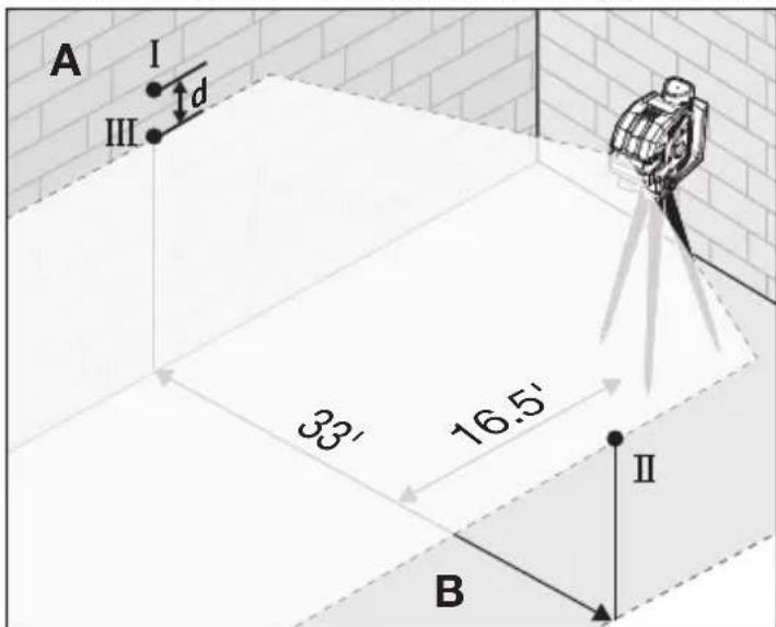
- For the Measuring distance of 2 × 33' = 66' , the maximum allowable deviation (d) is: 66' × ± 1/8" ÷ 33' = ± 1/4" . Thus, the difference d between points I and III should not exceed 1/4'' (max.) at 66' .
Vertical Leveling Accuracy
A door opening with approximately 8 of space on each side of the opening is required for this check.
1. Securely mount the tool 8' from one side of the door opening.
2. Turn the tool to ON and to Vertical Plumb Line & Plumb Points Mode or Perpendicular Level, Plumb Points, and Horizontal Points mode.
3. Position the tool with the laser towards the door opening. Allow the tool to self-level.
4. Mark the center of the vertical laser line on the floor in the middle of the door opening (point I), at a distance of 8' beyond the door opening (point II), and at the upper edge of the door opening (point III).
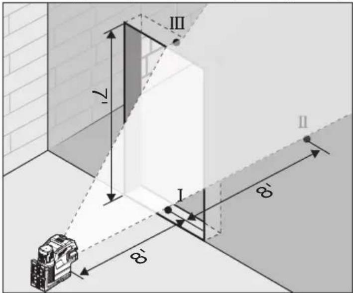
- Move the laser level directly behind point II on the other side of the door. Align the vertical laser line so the center is directly aligned with points I and II.
- Mark the center of the vertical line at the upper edge of the door opening (point IV).
- Measure the height of the door opening.
- The distance between points III and IV on the upper door opening is the vertical deviation (d) of the tool.
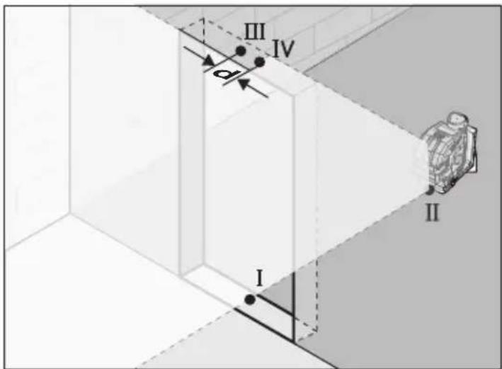
- The maximum vertical deviation (d) is: dmax = 2 x H (door opening) x ±1/8" ÷ 33'.
Example: for a door opening height of 7' , the maximum permitted deviation (d) is: d = 2 × 7' × ± 1/8'' ÷ 33' = ± 0.05''
Therefore, the measurement between points III and IV on the upper door opening should not exceed 0.05" in a 7' doorway.
Plumb Dot Accuracy
A free measuring distance of approximately 16.5 between floor and ceiling on a firm surface is required for this check.
- Place the tool within 1 of the floor.
- Turn the tool to ON and to Vertical Plumb Line Mode or Perpendicular Level, Plumb Points, and Horizontal Points mode.
- Set tool on ground and mark the center of the plumb point on the ceiling (point I). Also, mark the center of the plumb point on the floor (point II).
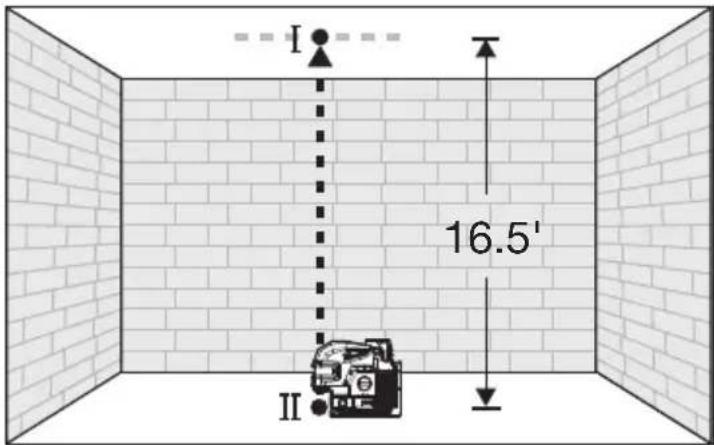
- Rotate the tool 180° . Align the center point of the laser beam directly onto the floor point II.
- Mark the center of the top plumb point on the reference line on the ceiling (point III).
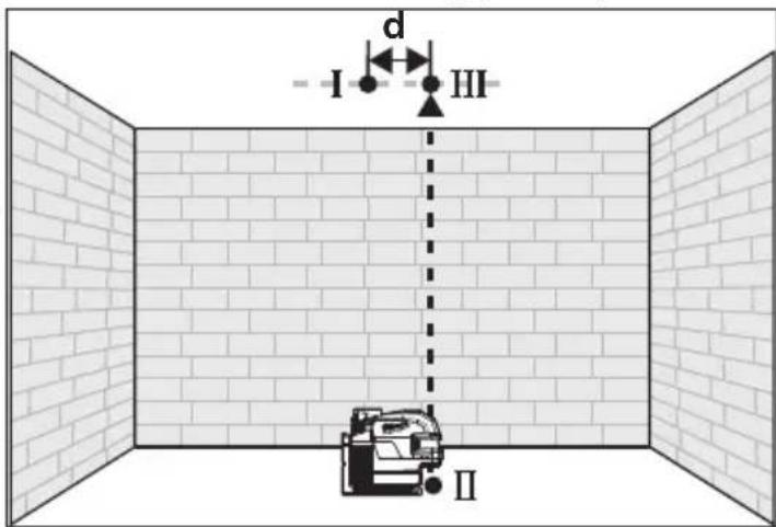
- The distance between points I and III on the ceiling is the deviation (d) of the tool. This distance should not exceed 1/8 (max.) at 33' .
For the Measuring distance of 2 × 16.5' = 33' , the maximum allowable deviation (d) is: 33' × ± 1/8" ÷ 33' = ± 1/8" .
Squaring Procedure
- Mark a reference (point x) on the floor that is equidistant from each wall in the center of a room. Turn ON the laser and switch to the "Unlocked" position. Ensure that laser is in Perpendicular Level, Plumb Points, and Horizontal Points mode (all lasers ON). Using the down plumb point, align the laser directly over the center of point (x) on the floor. With the laser in place, mark point (I) at the intersection of the lines directly in front of the laser on wall A. Without moving the laser, also mark the center of the right Horizontal point (II) on wall B.
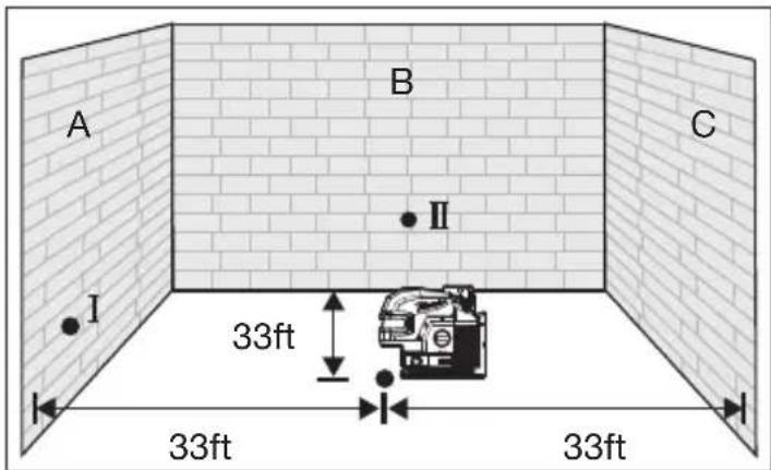
- Rotate the laser 90 degrees clockwise around plumb point (x) and align the left Horizontal dot with the previously marked point A. With the laser in position, mark point (III) on wall B at the intersection of the perpendicular lines directly in front of the laser. Without moving the laser, mark point (IV) on wall C using the right horizontal point. The deviation (d) between points II & III should be no more than 1/8 at 33' .
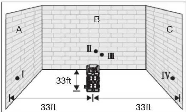
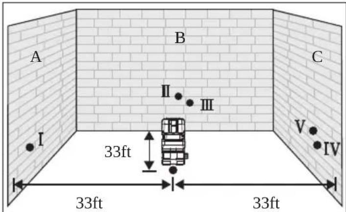
- Lastly, rotate the laser 180° clockwise around plumb point (x) so that the right horizontal point is aligned with the previously marked point I. Without moving the laser, using the left horizontal point mark (V) on wall C. The deviation (d) between points IV & V should be no more than 1/8" at 33'.
MAINTENANCE
WARNING To reduce the risk of injury, always remove the battery before performing any maintenance. Never disassemble the tool. Maintain Laser Level
Maintain tools. If damaged, have the tool repaired before use. Accidents may be caused by poorly maintained tools.
WARNING To reduce the risk of personal injury and damage, never immerse your tool in liquid or allow a liquid to flow inside them.
Cleaning
Clean dust and debris from any vents. Keep tool clean, dry and free of oil or grease. Use only mild soap and a damp cloth to clean, since certain cleaning agents and solvents are harmful to plastics and other insulated parts. Some of these include gasoline, turpentine, lacquer thinner, paint thinner, chlorinated cleaning solvents, ammonia and household detergents containing ammonia. Never use flammable or combustible solvents around tools.
Cleaning the Lenses
Blow off loose particles with clean compressed air. Carefully wipe the surface with a cotton swab moistened with water.
Repairs
For repairs, return the tool, battery pack and charger to the nearest authorized service center.
ACCESSIONS
WARNING Use only recommended accessories. Others may be hazardous.
For a complete listing of accessories, go online to www.milwaukeetool.com or contact a distributor.
SERVICE - UNITED STATES
1-800-SAWDUST (1.800.729.3878)
Monday-Friday, 7:00 AM - 6:30 PM CST or visit www.milwaukeetool.com
Contact Corporate After Sales Service Technical Support with technical, service/repair, or warranty questions.
Email: metproductsupport@milwaukeetool.com
Become a Heavy Duty Club Member at www.milwaukeetool.com to receive important notifications regarding your tool purchases.
SERVICE - CANADA
Milwaukee Tool (Canada) Ltd 1.800.268.4015
Monday-Friday, 7:00 AM - 4:30 PM CST
or visit www.milwaukeetool.ca
LIMITED WARRANTY USA&CANADA
Every MILWAUKEE power tool (see exceptions below) is warranted to the original purchaser only to be free from defects in material and workmanship. Subject to certain exceptions, MILWAUKEE will repair or replace any part on an electric power tool which, after examination, is determined by MILWAUKEE to be defective in material or workmanship for a period of five (5) years* after the date of purchase unless otherwise noted. Return of the power tool to a MILWAUKEE factory Service Center location or MILWAUKEE Authorized Service Station, freight prepaid and insured, is required. A copy of the proof of purchase should be included with the return product. This warranty does not apply to damage that MILWAUKEE determines to be from repairs made or attempted by anyone other than MILWAUKEE authorized personnel, misuse, alterations, abuse, normal wear and tear, lack of maintenance, or accidents.
Normal Wear: Many power tools need periodic parts replacement and service to achieve best performance. This warranty does not cover repair when normal use has exhausted the life of a part including, but not limited to, chucks, brushes, cords, saw shoes, blade clamps, o-rings, seals, bumpers, driver blades, pistons, strikers, lifters, and bumper cover washers.
*This warranty does not cover Air Nails & Staplers; Airless Paint Sprayer; Cordless Battery Packs; Gasoline Driven Portable Power Generators; Hand Tools; Hoist - Electric, Lever & Hand Chain; M12™ Heated Gear; Reconditioned Product; and Test & Measurement Products. There are separate and distinct warranties available for these products.
**The warranty period for Job Site Radios, M12TM Power Port, M18TM Power Source, Jobsite Fan and Trade TitanTM Industrial Work Carts is one (1) year from the date of purchase. The warranty period for the M18 FUEL™ 1" D-Handle High Torque Impact Wrenches, Drain Cleaning Cables, AIRSNAKE™ Drain Cleaning Air Gun Accessories, REDLITHIUM™ USB Laser Levels and TRAPSNAKE™ 25' Auger w/ CABLE DRIVE™ is two (2) years from the date of purchase. The warranty period for the M18™ Compact Heat Gun, 8 Gallon Dust Extractor, M18™ Framing Nails, M18 FUEL™ 1/2" Ext. Anvil Controlled Torque Impact Wrench w/ ONE-KEY™, M18 FUEL™ 1" High Torque Impact Wrench w/ ONE-KEY™, M18 FUEL™ 2 Gal. Compact Quiet Compressor, M12™ Laser Levels, 165' Laser Detector, M12™ 23GA Pin Nailer, M18 FUEL™ 1/4" Blind Rivet Tool w/ ONE-KEY™, M12 FUEL™ Low Speed Tire Buffer, M18 FUEL™ Random Orbital Polishers, and the M18™ Utility Fencing Stapler is three (3) years from the date of purchase. The warranty period for the LED in the LED Work Light and the LED Upgrade Bulb for the Work Light is the lifetime of the product subject to the limitations above. If during normal use the LED or LED Bulb fails, the part will be replaced free of charge.
Warranty Registration is not necessary to obtain the applicable warranty on a MILWAUKEE power tool product. The manufacturing date of the product will be used to determine the warranty period if no proof of purchase is provided at the time warranty service is requested. ACCEPTANCE OF THE EXCLUSIVE REPAIR AND REPLACEMENT REMEDIES DESCRIBED HEREIN IS A CONDITION OF THE CONTRACT FOR THE PURCHASE OF EVERY MILWAUKEE PRODUCT. IF YOU DO NOT AGREE TO THIS CONDITION, YOU SHOULD NOT PURCHASE THE PRODUCT. IN NO EVENT SHALL MILWAUKEE BE LIABLE FOR ANY INCIDENTAL, SPECIAL, CONSEQUENTIAL OR PUNITIVE DAMAGES, OR FOR ANY COSTS, ATTORNEY FEES, EXPENSES, LOSSES OR DELAYS ALGEGED TO BE AS A CONSEQUENCE OF ANY DAMAGE TO, FAILURE OF, OR DEFECT IN ANY PRODUCT INCLUDING, BUT NOT LIMITED TO, ANY CLAIMS FOR LOSS OF PROFITS. SOME STATES DO NOT ALLOW THE EXCLUSION OR LIMITATION OF INCIDENTAL OR CONSEQUENTIAL DAMAGES, SO THE ABOVE LIMITATION OR EXCLUSION MAY NOT APPLY TO YOU. THIS WARRANTY IS EXCLUSIVE AND IN LIEU OF ALL OTHER EXPRESS WARRANTYES, WRITTEN OR ORAL. TO THE EXTENT PERMITTED BY LAW, MILWAUKEE DISCLAIMS ANY IMPLIED WARRANTYES, INCLUDING WITHOUT LIMITATION ANY IMPLIED WARRANTY OF MERCHANTABILITY OR FITNESS FOR A PARTICULAR USE OR PURPOSE; TO THE EXTENT SUCH WARRANTYER IS NOT PERMITTED BY LAW, SUCH IMPLIED WARRANTYES ARE LIMITED TO THE DURATION OF THE APPLICABLE EXPRESS WARRANTY AS DESCRIBED ABOVE. SOME STATES DO NOT ALLOW LIMITATIONS ON HOW LONG AN IMPLIED WARRANTY LASTS, SO THE ABOVE LIMITATION MAY NOT APPLY TO YOU, THIS WARRANTYY GIVES YOU SPECIFIC LEGAL RIGHTS, AND YOU MAY ALSO HAVE OTHER RIGHTS WHICH VARY FROM STATE TO STATE.
This warranty applies to product sold in the U.S.A. and Canada only. Please call the 'Service Center Search' in the Parts & Service section of MILWAUKEE's website www.milwaukeetool.com or call 1.800. SAWDUST (1,800.729.3878) to locate your nearest service facility for warranty and non-warranty service on a Milwaukee electric power tool.
RÉGLES DE SECURITE GÉNÉRALES RELATIVES AUX OUTILS ÉLECTRIQUES
AVENTISSEMENT
(-4°F to 120°F)
Milwaukee Tool (Canada) Ltd
1.800.268.4015
Monday-Friday, 7:00 AM - 4:30 PM CST
www.milwaukeetool.ca
GARANTIE LIMITEE - AUX ETATS-UNIS ET A CANADA
(-4°F to 120°F)
11560 Polanco V Section
Miguel Hidalgo, Distrito Federal, Mexico
01 (800) 030-7777 o (55) 4160-3540
Lunes a Viernes (9am a 6pm)
O contactanos en www.milwaukeetool.com.mx
GARANTÍA LIMITADA -E.U.A. Y CANADA
13135 West Lisbon Road
Brookfield, WI 53005 USA


- LASER SAFETY
- WARNING
- WORK AREA SAFETY
- PERSONAL SAFETY
- BATTERY TOOL USE AND CARE
- SPECIFIC SAFETY RULES FOR LASER LEVELS
- SPECIFICATIONS
- ASSEMBLY
- POWER SAVE
- FUEL GAUGE
- MOUNTING/ADJUSTING THE LASER LEVEL
- CAUTION
- TURNING ON/OFF
- USING THE LASER LEVEL
- TROUBLESHOOTING
- ACCURACY FIELD CHECK
- INFLUENCES ON ACCURACY
- HORIZONTAL HEIGHT ACCURACY
- HORIZONTAL LEVELING ACCURACY
- VERTICAL LEVELING ACCURACY
- PLUMB DOT ACCURACY
- SQUARING PROCEDURE
- MAINTENANCE
- WARNING TO REDUCE THE RISK OF INJURY, ALWAYS REMOVE THE BATTERY BEFORE PERFORMING ANY MAINTENANCE. NEVER DISASSEMBLE THE TOOL. MAINTAIN LASER LEVEL
- WARNING TO REDUCE THE RISK OF PERSONAL INJURY AND DAMAGE, NEVER IMMERSE YOUR TOOL IN LIQUID OR ALLOW A LIQUID TO FLOW INSIDE THEM
- CLEANING
- CLEANING THE LENSES
- REPAIRS
- ACCESSIONS
- WARNING USE ONLY RECOMMENDED ACCESSORIES. OTHERS MAY BE HAZARDOUS
- SERVICE - UNITED STATES
- 1-800-SAWDUST (1.800.729.3878)
- SERVICE - CANADA
- MILWAUKEE TOOL (CANADA) LTD 1.800.268.4015
- LIMITED WARRANTY USA&CANADA
- RÉGLES DE SECURITE GÉNÉRALES RELATIVES AUX OUTILS ÉLECTRIQUES
- AVENTISSEMENT
- MILWAUKEE TOOL (CANADA) LTD
- 1.800.268.4015
- GARANTIE LIMITEE - AUX ETATS-UNIS ET A CANADA
- GARANTÍA LIMITADA -E.U.A. Y CANADA
Brand : MILWAUKEE
Model : M12 3624-20
Category : Laser level