
RAK190V - Thermostat GE - Free user manual and instructions
Find the device manual for free RAK190V GE in PDF.

| Product Type | Programmable Thermostat |
| Brand | GE |
| Model | RAK190V |
| Power Supply | 24 VAC (18-30 VAC) |
| Adjustment Range | 60°F to 85°F (16°C to 29°C) |
| Operating Ambient Temperature | 40°F to 99°F (4°C to 37°C) |
| Occupancy Sensor | Range 5 m, field of view 109.6° x 109.6° |
| Max Stages (Heating/Cooling) | Heating 3 stages, Cooling 2 stages |
| Communication | Bidirectional (RS485) or Standard (8 wires) |
| Relay Outputs | O1/O2: dry contact, 0.5 A @ 32 VAC or 5 A @ 30 VDC |
| Operating Humidity | 0 to 95% RH, accuracy ±5% |
| Dimensions (H x W x D) | 3.9 x 5.4 x 1.03 inches (99 x 137 x 26 mm) |
| Display | LCD screen with backlight |
| Main Functions | Heating, cooling, fan, auto-changeover, occupancy-based energy savings |
| Fan Speeds | High and Low (2-pipe mode); Auto Low and Auto High (8-wire mode) |
| Warranty | 1 year, full replacement |
| Reset | Factory settings via installer menu (option 99) |
| Compliance | FCC Part 15 Class B, ICES-003 |
| Installation | Wall mounting, recommended height 1.5 m |
| Package Contents | Cover, thermostat, screws, wall anchors, connectors |
| Safety | Cut power before installation; do not exceed electrical specifications |
Frequently Asked Questions - RAK190V GE
User questions about RAK190V GE
0 question about this device. Answer the ones you know or ask your own.
Ask a new question about this device
Download the instructions for your Thermostat in PDF format for free! Find your manual RAK190V - GE and take your electronic device back in hand. On this page are published all the documents necessary for the use of your device. RAK190V by GE.
USER MANUAL RAK190V GE
USING THE THERMOSTAT
OVERVIEW....15
TROUBLESHOOTING ....16
RESETTING ....16
WARRANTY 17
FCC STATEMENT 18
SPECIFICATIONS
| Electrical Rating: | |
| Input-Hardwire 24 VAC (18-30 VAC) | |
| Load -1 amp maximum per output-4 amp maximum total load | |
| Setpoint Range 60° to 85° F | (16° to 29°C) |
| Operating Ambient 40° F to 99° F (4°C to 37°C) | |
| Occupancy Sensor Range 5 | meters, 109.6 degrees x 109.6 degreesField of View |
| O1/O2 Dry Contact Ratings | .5A @ 32VAC or .5A @ 30VDC |
| Humidity Range/Accuracy 0 | to 95% operating humidity range, +/- 5% accuracy |
| Shipping Temperature Range | -30°F to + 150°F (-34° to +65°C) |
| Thermostat Dimensions 3.9" | H x 5.4" W x 1.03" |
MERCURY NOTICE: This product does not contain mercury. However, this product may replace a product that contains mercury. Mercury and products containing mercury must not be discarded in household trash. Refer to thermostat-recycle.org for information on disposing of products containing mercury.
| Thermostat Applications Maxim | um Stages Heat/ Cool |
| Single Stage Cooling, One or Two Stage HeatingNOTE: Two stage heating = 1st stage heat pump and 2nd stage resistance heat | 3/2 |
| Two Stage Cooling, Three Stage HeatingNOTE: Three stage heating = 2 stage heat pump and 3rd stage resistance heat | |
| 2-Way Communication with select GE Appliance products |
WARNING
ELECTRICAL SHOCK HAZARD — Turn off power by unplugging the unit or by removing the fuse or switching the appropriate circuit breaker to the OFF position before removing the existing thermostat. Failure to do so could result in risk of electric shock.
PACKAGE CONTENTS/TOOLS REQUIRED:
Package includes:
- Thermostat base
- Thermostat
- Screws
- Wall anchors
• 2-Way and 1-Way Thermostat Connectors
Tools needed:
- Drill with 3/16" bit
- Hammer
- Screwdriver
- Putty
TO REMOVE EXISTING THERMOSTAT
- Turn off power to heating and cooling system by removing the fuse or switching off the appropriate circuit breaker.
- Remove cover of old thermostat. This should expose the wires.
- Remove wires from wire terminals. Note which color wires are attached to each terminal.
- Remove existing thermostat base from wall.
- Refer to the following section for instructions on how to install this thermostat.
TO INSTALL THERMOSTAT
IMPORTANT: Thermostat installation must conform to local and national building and electrical codes and ordinances.
NOTE: Mount the thermostat about five feet above the floor. Do not mount the thermostat on an outside wall, in direct sunlight, behind a door or in an area affected by a vent or duct.
- Turn off power to the heating and cooling system by removing the fuse or switching off the appropriate circuit breaker.
- Loosen (do not remove) the screw on the bottom of the thermostat assembly to remove thermostat from base.
- Put thermostat base against the wall where you plan to mount it. Make sure wires will feed through the wire opening in the base of the thermostat. Ensure enough clearance to dress excess wire slack.
- With the base level, mark the placement of the mounting holes.
- Set thermostat base and thermostat away from working area.
- Using a 3/16" drill bit, drill holes in the locations you have marked for mounting.
- Use a hammer to tap supplied anchors in mounting holes.
- Align thermostat base with mounting holes and feed the control wires through the wire opening.
- Seal hole for wires behind thermostat with non-flammable insulation or putty, or use a wall plate obtainable from a local hardware or home building store.
- Use supplied screws to mount thermostat base to wall.
- Insert stripped wires in matching wire terminals by pressing on the corresponding terminal contact. See the "Wiring" section of this manual.
NOTICE
Make sure exposed portion of wires do not touch other wires.
- Gently tug wire to be sure of proper connection. Double check that each wire is connected to the proper terminal.
- Replace thermostat by snapping it in place and tighten bottom screw.
- Plug the unit in or turn on power to the system at the main service panel.
- Test thermostat operation in all modes (fan only, cooling, heating and both fan speeds).
WIRING
Refer to equipment manufacturer's instructions for specific system wiring information. After wiring, see INSTALLER MENU for proper thermostat configuration.
This thermostat is capable of two different wiring communication types:
1) 2-Way Communication: This communication may not be available for all single speed compressor models. This is the preferred form of communication for our variable speed compressor models. This communication protocol provides temperature and humidity data to the variable speed unit to optimize operation. Wiring to the unit will be made with a 4 or 5 wire connector. If your unit came with a 5 pin/5 wire connector, please see Diagram 2. Otherwise, please use the 5 pin/4 wire connector included with this thermostat and refer to Diagram 1.
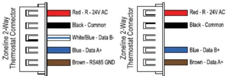
5 Pin / 5 Wire Connector 5 Pin / 4 Wire Connector
2) Standard (1-Way) Communication: This is conventional thermostat thermostat communication where the thermostat provides only relayed signals for the unit to respond to. For this method, wiring to the unit will be completed using an 8 pin connector:

Wiring diagrams on the following pages are for typical systems and describe the thermostat terminal functions.
Precautions
- Do not exceed the specification ratings.
- All wiring must conform to local and national electrical codes and ordinances.
- This control is a precision instrument, and should be handled carefully. Rough handing or distorting components could cause the control to malfunction.
WARNING
Do not use on circuits exceeding
specified voltage. Higher voltage will damage control and could cause shock or fire hazard.
Do not short out terminals on primary control to test. Short or incorrect wiring will burn out thermostat and could cause personal injury and/or property damage.
CAUTION
To prevent electrical shock
and/or equipment damage, disconnect electrical power to system, at main fuse or circuit breaker box, until installation is complete.
Diagram 1: 2-Way Communication Wiring (5 Pin / 4 Wire) - used with AZV & AVV models
Note: 2-way communication provides variable speed models with temperature & humidity data to optimize performance.
A link icon (see page 15) will be displayed on the thermostat when a successful 2-way connection has been made.
For make up air models: To deliver make-up air only when a room is occupied, be sure to enable make-up air occupancy control on the unit (mode b2).
Note: Colors Mentioned on Diagram Match Leads on Zoneline 2-Way Connector below.
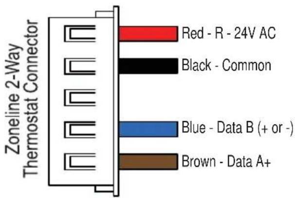
Red - R - 24V AC
Black - Common
Brown - Data A+
Blue - Data B (+ or -)
Diagram 2: 2-Way Communication Wiring (5 Pin / 5 Wire) - used with AZ9V Models only. AZ9VH12DBMH1 & AZ9VH12EBMH1 will require a software update.
To update, contact zoneline.requests@GEAppliances.com
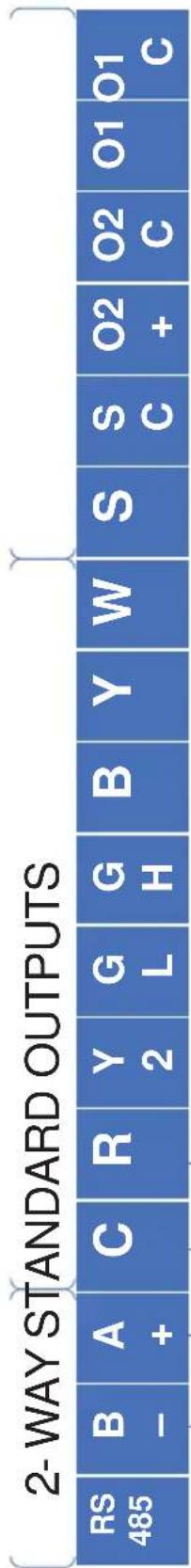
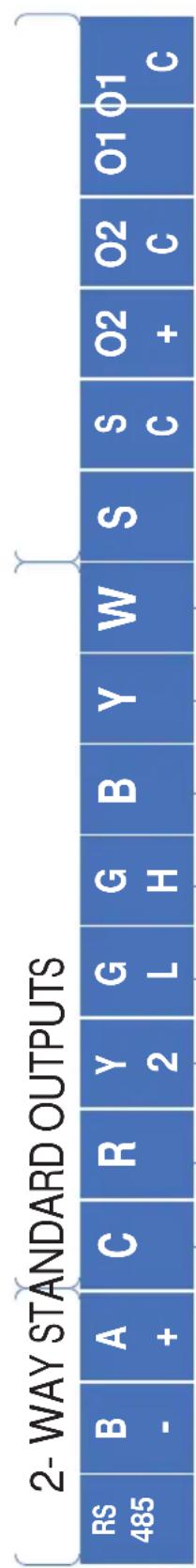
| 2- WAY STANDARD OUTPUTS | |||||||||||||||
| RS 485 | B - | A + | C | R | Y 2 | G L | G H | B | Y | W | S | S C | O2 + | O2 C | O1 O1 C |
Note: 2-way communication provides variable speed models with temperature & humidity data to optimize performance.
A link icon (see page 15) will be displayed on the thermostat when a successful 2-way connection has been made. Mode 6 on the VTAC will must be set to "6u".
For make up air models: To deliver make-up air only when a room is occupied, be sure to enable mode "E" in the auxiliary controls of the air conditioner.
Note: Colors Mentioned on Diagram Match Leads on Zoneline 2-Way Connector below.
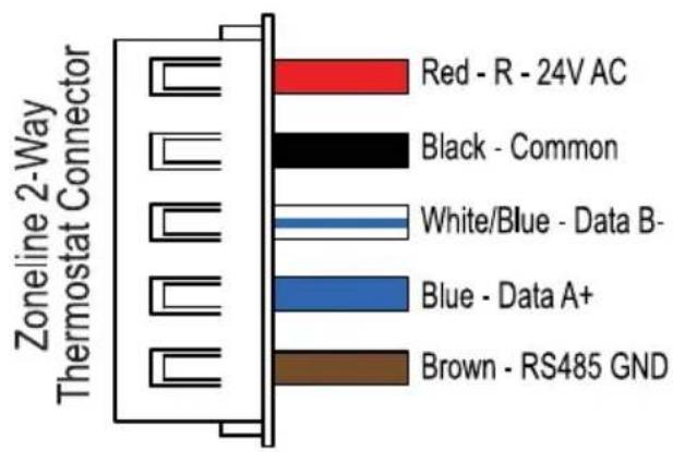
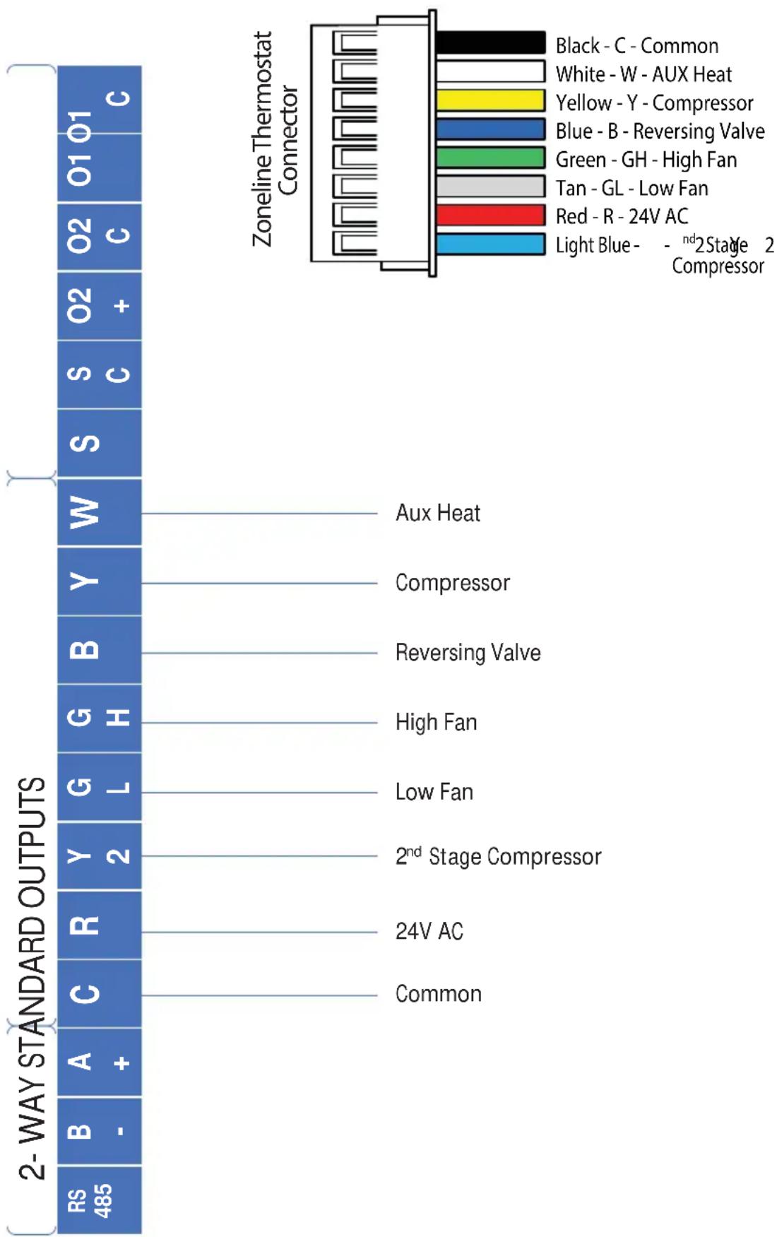
Diagram 3: Standard Communication Wiring (3 Heat / 2 Cool), Factory Default
bar
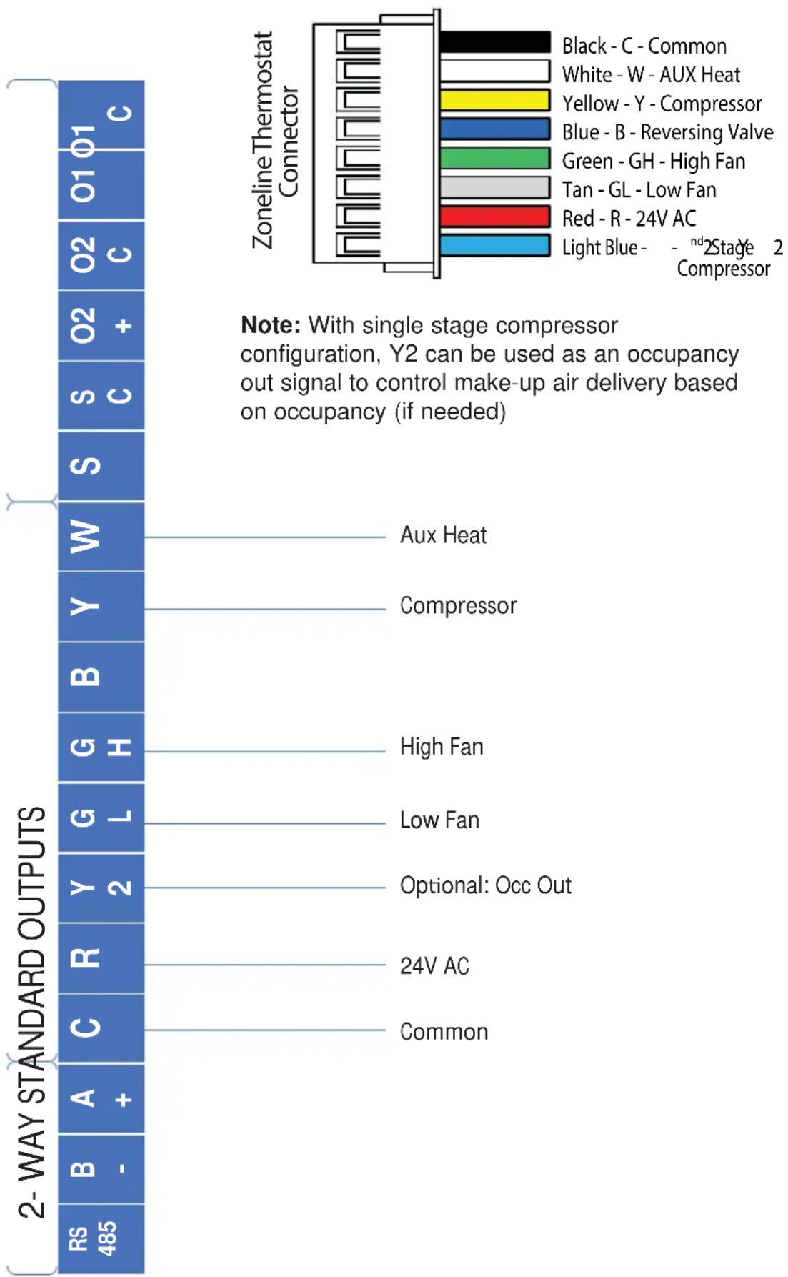
Zoneline Thermostat Connector | Component | Rating | | :--- | :--- | | Black - C - Common | 1 | | White - W - AUX Heat | 1 | | Yellow - Y - Compressor | 1 | | Blue - B - Reversing Valve | 1 | | Green - GH - High Fan | 1 | | Tan - GL - Low Fan | 1 | | Red - R - 24V AC | 1 | | Light Blue - -ndStage 2 Compressor | 1 | | Component | Rating | | :--- | :--- | | Aux Heat | 0 | | Compressor | 0 | | Reversing Valve | 0 | | High Fan | 0 | | Low Fan | 0 | | 2nd Stage Compressor | 0 | | 24V AC | 0 | | Common | 0 | 2-WAY STANDARD OUTPUTS RS 485 B - A + C R Y G H Y B Y W 2 Common 2-ND STANDARD OUTPUTS Aux Heat Compressor Reversing Valve High Fan Low Fan 24V AC CommonDiagram 4: Standard Communication Wiring (2 Heat / 1 Cool)
bar
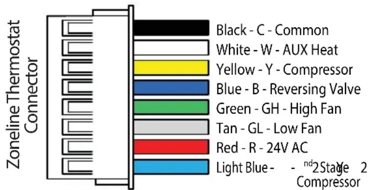
| Component | Color | | --------- | ----- | | Black - C - Common | Black | | White - W - AUX Heat | White | | Yellow - Y - Compressor | Yellow | | Blue - B - Reversing Valve | Blue | | Green - GH - High Fan | Green | | Tan - GL - Low Fan | Gray | | Red - R - 24V AC | Red | | Light Blue - - ndStage 2 Compressor | Blue |Note: With single stage compressor configuration, Y2 can be used as an occupancy out signal to control make-up air delivery based on occupancy (if needed)
Diagram 5: Standard Communication Wiring (1 Heat / 1 Cool)
bar
Zoneline Thermostat Connector | Category | Rating | | :--- | :--- | | Black - C - Common | 1 | | White - W - AUX Heat | 1 | | Yellow - Y - Compressor | 1 | | Blue - B - Reversing Valve | 1 | | Green - GH - High Fan | 1 | | Tan - GL - Low Fan | 1 | | Red - R - 24V AC | 1 | | Light Blue - -ndStage 2 Compressor | 1 | Note: With single stage compressor configuration, Y2 can be used as an occupancy out signal to control make-up air delivery based on occupancy (if needed) 2-WAY STANDARD OUTPUTS | Rating | Value | | :--- | :--- | | RS 485 | 1 | | B - | 1 | | A + | 1 | | C | 1 | | R | 1 | | Y 2 | 1 | | G L | 1 | | H | 1 | | G H | 1 | | B Y | 1 | | W W | 1 | | S C | 1 | | O2 + | 1 | | O2 C | 1 | Note: With single stage compressor configuration, Y2 can be used as an occupancy out signal to control make-up air delivery based on occupancy (if needed)INSTALLER MENU
To access the INSTALLER MENU, use the Power button to turn the thermostat OFF. While OFF, press and hold the Mode and + button for 2 seconds until "Setup Mode" is shown on the display.
Once in the menu:
• + / - : change setting selection
- Mode: advances to next menu item
• F a n : returns to previous menu item
• Power: saves changes and exits
Note: After two minutes of no key presses, Menu times out and returns to Power Off black screen.

INSTALLER MENU (cont)
| Menu Item (Mode advances to next, Fan returns to previous) | Description | Default Setting | Range/Selections (+ or - to change) | 8 Wire Setting Availability | 2- Way Setting Availability |
| 01 | Units (F=Fahrenheit or C=Celsius) | FF,C | √ | ||
| 02 | Set Current Hours (military time)Only used if Scheduling Energy Savings (setting 20) | 0 | 0 t | √ o | √ 2 |
| 03 | Set Current MinutesOnly used if Scheduling Energy Savings (setting 20) | 0 | 0 t | √ o | √ 5 |
| 06 | Fan ModeA = Auto, only allows auto (cyclic) fan selection in heating/ cooling modesC = Continuous, allows selection of continuous or auto (cyclic) in heating/cooling modes | C | A , | √ C | |
| 07 | Heat PumpIs the unit a heat pump? Y=Yes, n= No | Y | Y , | √ n | |
| 08 Reversing Valve Type b b , | O | √ | |||
| 09 | Number of Compressor Stages | 2 | 1 , | √ 2 | |
| 10 | Heating Differential 1Number of degrees (F) from set point required to activate 1st stage heat | 1 | 1 t | √ o | 1 |
| 11 | Cooling Differential 1Number of degrees (F) from set point required to activate 1st stage cool | 1 | 1 t | √ o | 1 |
| 12 | Heating Differential 2Number of degrees (F) from 1st stage heat required to activate 2nd stage heat | 1 | 1 t | √ o | 1 |
| 13 | Cooling Differential 2Number of degrees (F) from 1st stage cool required to activate 2nd stage cool | 1 | 1 t | √ o | 1 |
| 14 | Heating Differential 3Number of degrees (F) from 2nd stage heat required to activate 3rd stage heat | 1 | 1 t | √ o | 1 |
| 15 | Auto ChangeoverY = enables autochangeover option under "Mode" | n | n , | √ Y | |
INSTALLER MENU (cont)
| Menu Item (Mode advances to next, Fan returns to previous) | Description | Default Setting | Range/Selections (+ or - to change) | 8 Wire Setting Availability | 2- Way Setting Availability |
| 16 | Deadband (F)This offset is added to both Cooling & Heating Differential 1 when in autochangeover modeNote: Setting is only available if autochangeover is enabled | 1 | 1 t | ✓ o | 1 |
| 17 | Min Cooling Temp (F)Note: Can't be a higher temperature than setting 18 | 66 | 60, 64, 66, 68, 70, 72, 74, 76 | ✓ | |
| 18 | Max Heating Temp (F)Note: Can't be a lower temperature than setting 17 | 78 | 65, 70, 72, 74, 76, 78, 80, 85 | ✓ | |
| 19 | Room Temp Offset (F)If needed, this is an offset to calibrate room temperature reading | 0 | - 9 | ✓ t | ✓ o |
| 20 | Humidity OffsetIf needed, this is an offset to calibrate room humidity reading | 0 | - 9 | ✓ t | ✓ o |
| 21 | Occupancy Energy savingsOF = No temperature setbacks are allowedY = Temperature setbacks are allowed when no occupancy is detectedS = Scheduled Energy Savings. Temperature setbacks are only allowed in the time window specified by settings 29 and 30. | Y OF, Y, S | ✓ | ✓ | |
| 22 | Occupancy Response Time (tenths of a second) | 1 0-30 | ✓ | ✓ | |
| 24 | Occupancy Cool Setback TemperatureThe number of degrees (F) the temperature is allowed to drift above setpoint in cooling with no occupants detectedNote: Only Available if Occupancy Energy Savings (setting 21) is set to Y or S | 3 0-15 | ✓ | ✓ | |
| 25 | Occupancy Heat Setback TemperatureThe number of degrees (F) the temperature is allowed to drift below setpoint in heating with no occupants detectedNote: Only Available if Occupancy Energy Savings (setting 21) is set to Y or S | 3 0-15 | ✓ | ✓ | |
| 26 Not Used - For Future Use 5 0-15 | ✓ | ||||
| 27 Not Used- For Future Use 5 0-15 | ✓ | ||||
INSTALLER MENU (cont)
| Menu Item (Mode advances to next, Fan returns to previous) | Description | Default Setting | Range/Selections (+ or - to change) | 8 Wire Setting Availability | 2- Way Setting Availability |
| 28 | Occupancy Status Timer (In minutes)The number of minutes occupancy status is maintained once an occupancy event occursNote: Only Available if Occupancy Energy Savings (setting 21) is set to Y or S | 30 | 0-99(100) by 5's | √ | √ |
| 29 | Scheduled Energy Savings Start Time (military time)If using Scheduled Energy Savings, select the start time when occupancy driven setbacks are permitted.Note: Only Available if Occupancy Energy Savings (setting 21) is set to S | 9 0-23 | √ | √ | |
| 30 | Scheduled Energy Savings Stop Time (military time)If using Scheduled Energy Savings, select the time when occupancy driven setbacks are no longer permittedNote: Only Available if Occupancy Energy Savings (setting 21) is set to S | 21 0-23 | √ | √ | |
| 31 | Device 1Used to control external relay wired to O1 output on terminal block | OF | OF - OFFnO - normally open,occupancy event closes circuitnC- normally closed,occupancy event opens circuitrO - not usedrC - not used | √ | √ |
| 32 | Device 2Used to control external relay wired to O2 output on terminal block | OF | √ | √ | |
| 99 | Defaults ResetSelecting Y restores all programming defaults after leaving the Installer Menu | n | n , | √ Y | √ |
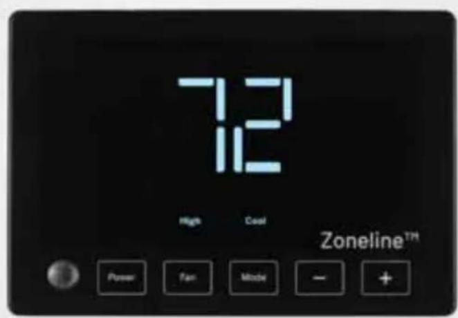
THERMOSTAT OVERVIEW
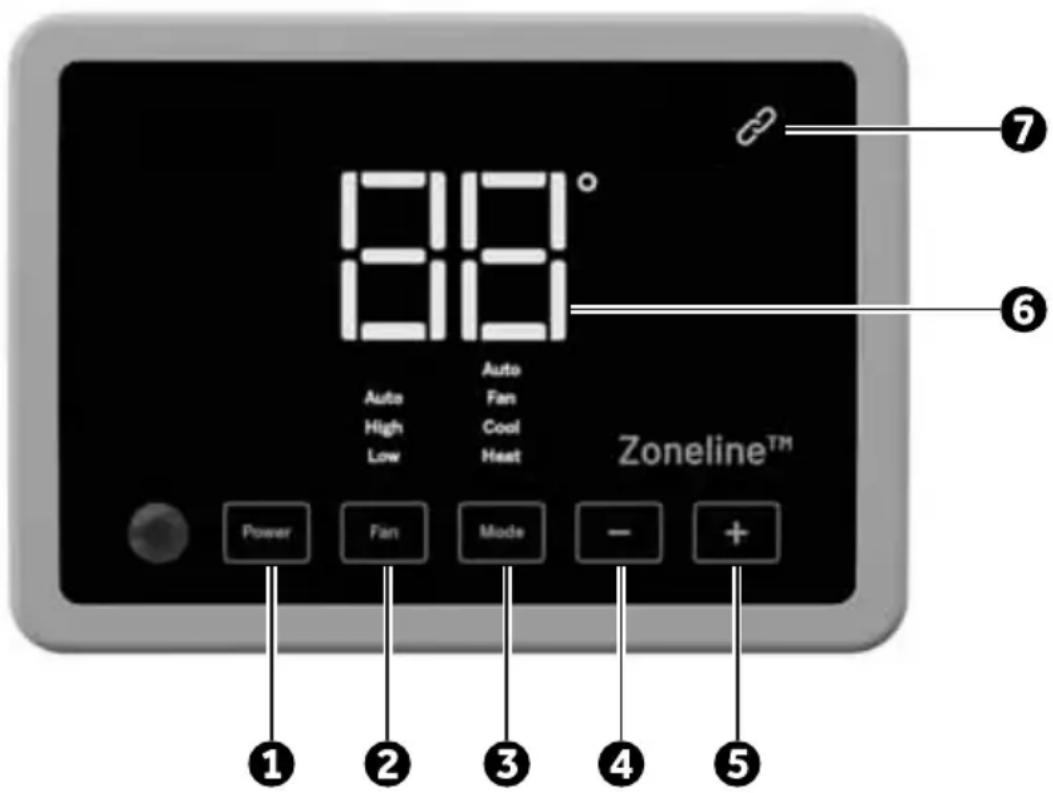
Before you begin using your thermostat, you should be familiar with its features, display and the location/operation of the thermostat buttons.
| THERMOSTAT BUTTONS AND SWITCHES THE DISPLAY | |
| 1.) Power 6.) Selected Setpoint | |
| 2.) Fan Selection– 2-way options: Low, High (auto or continuous based on Zoneline Auxiliary Mode #1 selection)– 8 wire options: Auto Low, Auto High, Low and High (if “C” is enabled in thermostat setting 6) | 7.) 2-Way Communication IndicatorSolid Link = ConnectedBlinking Link = Connection Issue |
| 3.) Mode Selection– 2-way options: Heat, Cool Fan– 8 wire options: Heat, Cool, Fan, Auto (Autochangeover)*Note: Auto must be enabled in setting 15 to be an available option | |
| 4.) Lower Setpoint | |
| 5.) Raise Setpoint | |
| Problem Solution | |
| No Display Press power button to ensure thermostat isn't off.Check for 24 VAC; display is blank when 24 VAC is not present | |
| System fan does not come on properly | Verify that wiring is correct. (Note: Variable Speed units have fan that ramps up and down slowly) |
| All thermostat buttons are inoperative | Verify that 24 VAC is present; unit will not operate when 24 VAC is not present. |
| Thermostat turns on and off too frequently | Adjust temperature differential (see Configuration Mode - Setting Temperature Differential, Stage 1, Stage 2, and Stage 3 section). |
| Fan runs continuously Check fan selection. If set to High or Low in 8-wire mode, fan will run continuously. If thermostat is in 2-way control mode, verify the Auxiliary settings of the Zoneline HVAC unit. | |
| Compressor doesn't run or turn off immediately when changing function or setting | There is a 3 minute time delay and a 3 minute minimum run time for the compressor when it turns on/off. |
| Fan doesn't run or turn off immediately when changing function or setting | This is normal. On some models, the fan may have a minimum run time/off time delay. |
Resetting the Thermostat or Thermostat Settings
To conveniently reset only the user settings back to factory defaults, see setting 99 in the Installer Menu.
WARNING
This product contains a chemical known to the state of California to cause cancer and birth defects and other reproductive harm.
LIMITED WARRANTY
Staple your receipt here. Proof of the original purchase date is needed to validate the warranty.
| For The Period Of GE Appliances Will Replace : | |
| One Year From the date of the original purchase | Full Replacement of the thermostat which fails due to a defect in materials or workmanship. For Warranty replacement, contact your distributor. |
What GE Appliances Will Not Cover:
■ Service trips to your location.
- Improper installation. If you have an installation problem, contact your installer. You are responsible for providing adequate electrical connections to the product.
- Failure of the product resulting from modifications to the product or due to unreasonable use, including failure to provide reasonable and necessary maintenance.
In commercial locations, labor necessary to move the unit, after it has been initially installed, to a location where it is accessible for service by an individual technician; or, if the instructions included in this manual have been disregarded.
■ Replacement of location fuses or the resetting of circuit breakers.
■ Damage to the product caused by improper power supply voltage, accident, fire, floods or acts of God.
■ Incidental or consequential damage caused by possible defects with this thermostat.
EXCLUSION OF IMPLIED WARRANTIES—Your sole and exclusive remedy is product exchange as provided in this Limited Warranty. Any implied warranties, including the implied warranties of merchantability or fitness for a particular purpose, are limited to one year or the shortest period allowed by law.
This warranty is extended to the original purchaser and any succeeding owner for products purchased for use within the USA and Canada.
In Alaska, the warranty excludes the cost of shipping or service calls to your site.
Some states or provinces do not allow the exclusion or limitation of incidental or consequential damages. This warranty gives you specific legal rights, and you may also have other rights which vary from state to state or province to province. To know what your legal rights are, consult your local, state or provincial consumer affairs office or your state's Attorney General.
Warrantor: GE Appliances, a Haier company
Louisville, KY 40225
NOTE: This equipment has been tested and found to comply with the limits for a Class B digital device, pursuant to part 15 of the FCC Rules. These limits are designed to provide reasonable protection against harmful interference in a residential installation. This equipment generates, uses and can radiate radio frequency energy and, if not installed and used in accordance with the instructions, may cause harmful interference to radio communications. However, there is no guarantee that interference will not occur in a particular installation. If this equipment does cause harmful interference to radio or television reception, which can be determined by turning the equipment off and on, the user is encouraged to try to correct the interference by one or more of the following measures:
- Reorient or relocate the receiving antenna
- Increase the separation between the equipment and receiver
- Connect the equipment into an outlet on a circuit different from that to which the receiver is connected
- Consult the dealer or an experienced radio/TV technician for help
CAN ICES-003 (B) / NMB-003 (B)
Garant : GE Appliances, Louisville, KY 40225

- SPECIFICATIONS
- WARNING
- PACKAGE CONTENTS/TOOLS REQUIRED:
- Package includes:
- Tools needed:
- TO REMOVE EXISTING THERMOSTAT
- TO INSTALL THERMOSTAT
- IMPORTANT: Thermostat installation must conform to local and national building and electrical codes and ordinances.
- NOTICE
- Make sure exposed portion of wires do not touch other wires.
- WIRING
- Precautions
- CAUTION
- INSTALLER MENU
- Once in the menu:
- THERMOSTAT OVERVIEW
- Resetting the Thermostat or Thermostat Settings
- LIMITED WARRANTY
- What GE Appliances Will Not Cover:
Brand : GE
Model : RAK190V
Category : Thermostat