
RAK180W1 - Thermostat GE - Free user manual and instructions
Find the device manual for free RAK180W1 GE in PDF.


| Product Type | Programmable Thermostat |
| Brand | GE |
| Model | RAK180W1 |
| Dimensions (W x H x D) | 4.5 x 4.5 x 1.5 inches |
| Weight | 0.5 lbs |
| Power Supply | 24V AC (hardwired) |
| Backup Battery | 2 AA alkaline batteries (not included) |
| Display Type | LCD with backlight |
| Programmable | Yes, 7-day programming |
| Temperature Range | 40°F to 90°F (4°C to 32°C) |
| Accuracy | ±1°F |
| Compatibility | Single-stage heat/cool systems |
| Fan Control | Auto/On modes |
| Key Features | Large display, programmable schedule, filter reminder |
| Cleaning Instructions | Wipe with a soft, damp cloth; do not use solvents |
| Safety | UL listed; automatic shut-off for protection |
| Spare Parts Availability | Battery compartment cover, mounting plate |
| Repairability | Easy DIY installation; replace batteries as needed |
Frequently Asked Questions - RAK180W1 GE
User questions about RAK180W1 GE
0 question about this device. Answer the ones you know or ask your own.
Ask a new question about this device
Download the instructions for your Thermostat in PDF format for free! Find your manual RAK180W1 - GE and take your electronic device back in hand. On this page are published all the documents necessary for the use of your device. RAK180W1 by GE.
USER MANUAL RAK180W1 GE
Wireless Thermostat with Occupancy Sensor
OWNER'S MANUAL & INSTALLATION INSTRUCTIONS
RAK180W1
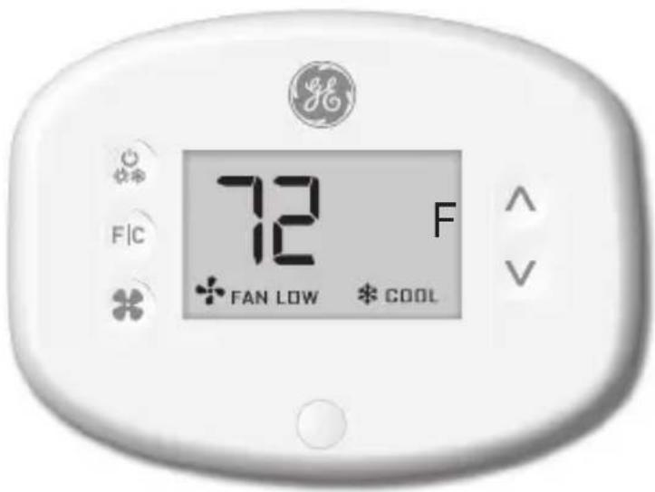
THANK YOU FOR MAKING GE APPLIANCES A PART OF YOUR HOME.
Whether you grew up with GE Appliances, or this is your first, we're happy to have you in the family.
We take pride in the craftsmanship, innovation and design that goes into every GE Appliances product, and we think you will too.

GE APPLIANCES
Table of Contents
Safety Information 4
Before You Begin....5
Thermostat Installation 7
Installing the Wireless Control card....7
Wireless Installation....10
Wired Installation 10
Thermostat Configuration....11
Setting the clock 12
Entering the room number 13
Configuring the Equipment Settings - Compressor Type ....14
Configuring the Equipment Settings - Electric Heat 15
Configuring the Equipment Settings - Reversing Valve 16
Configuring the Energy Saving Settings....17
Custom Energy Savings Settings.... 19
Using the Thermostat Settings Screens 20
01 – FAN CONTROL MODE ....21
02 – 1ST STAGE DIFFERENTIAL - HEAT ......22
03 – 2ND STAGE DIFFERENTIAL - HEAT ......23
04 – 1ST STAGE DIFFERENTIAL - COOL ......24
05 - INCIDENTAL OCCUPANCY THRESHOLD 25
06 – NIGHT OCCUPANCY THRESHOLD ......26
07-FORCED 2ND STAGE HEATING 27
08-NIGHT OCCUPANCY START 28
09-NIGHT OCCUPANCY END 29
10 – TEMPERATURE RECOVERY TIME ....30
11 - RECOVERY TEMPERATURE - HEAT 31
12 - TEMPERATURE SETBACK DELAY - HEAT 32
13 – MINIMUM SETBACK TEMPERATURE ....33
14 - TEMPERATURE SETBACK DELAY - COOL 34
15-MAXIMUM SETBACK TEMPERATURE 35
16 - RECOVERY TEMPERATURE - COOL 36
17-MINIMUM SET POINT 37
18 - MAXIMUM SET POINT....38
19 – TEMPERATURE CONTROL MODE ....39
20 - AUTO CHANGEOVER SET POINT OFFSET (DEAD BAND) 40
21 – SETBACK SET POINTS / AUTO-RESTORE 41
22 – AUTOMATIC HUMIDITY CONTROL†......42
23 - TEMPERATURE CALIBRATION ....43
Thermostat Maintenance....44
Troubleshooting 45
Appendix 1 - Energy Saving Presets ......48
Technical Specifications....49
Limited Warranty 50
IMPORTANT SAFETY INFORMATION READ ALL INSTRUCTIONS BEFORE USING
WARNING
FIRE AND SHOCK HAZARD
- Always turn off power at the main power supply before installing, cleaning or removing the thermostat. Failure to do so could result in electrical shock hazard.
- Do not use on voltages over 30 VAC. Higher voltages will damage the thermostat and could cause shock or fire hazard.
NOTICE
- All wiring must conform to local and national electrical and building codes.
- Use this thermostat only as described in this manual.
Specifications.
Electrical rating: • 24 VAC (18–30 VAC)
•
•
Operating temperature range: 40°F–99°F (4°C–37°C)
System Configurations:
* 1 stage cool, 2 stage heat (heat pump/resistance heat) 1 stage cool, 1 stage heat (resistance heat)
Terminations: *R, C, W, Y, GH, GL, B for 2-stage heat R, C, W, Y, GH, GL, for 1-stage heat
Wiring: Maximum wiring length is 66ft (20 meters) for AWG18 Maximum wiring length is 60ft (18 meters) for AWG20
*Default setting
- Determine the appropriate installation location for the thermostat
The thermostat should face the bed area of the room.
The thermostat must not be installed near or on metal structures or surfaces including metal air ducting that may be in the wall.
Metal structures and surfaces significantly reduce the range of the wireless signal.
A. Refer to the Zoneline Owner's Manual to change the AUX setting to 6A (class 2 mode). The unit will display "use wall thermostat" when finished.
B. Zoneline output is 24VAC. Be sure the jumper on the wireless control card is on the AC position – jumper is connecting “R” and “C” (common) pins. This is the default position.
Other Zoneline Auxiliary Control Settings for use with *DBM & *EBM Models
- Mode E: Enables Zoneline Makeup air vent door control based on occupancy; default is off and mode must be turned on to utilize this feature.
- Refer to the Zonelines Owner's Manual for instructions on how to change this AUX setting/mode.
NOTE: This section is not required unless the thermostats are networked
Pairing the Thermostat and the Control Card: In case of Network Installation with online management, the thermostat and the Control Card must be paired with a Network Programmer specific to the property before the installation. Note: Thermostat and Control Card are factory paired.
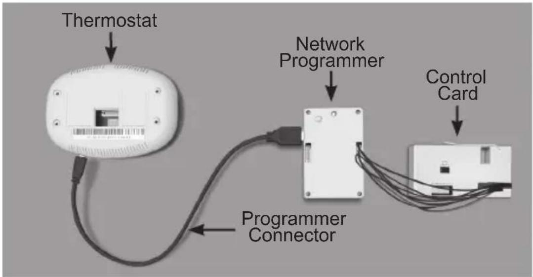
The thermostat and control card must not be powered during the pairing procedure - remove batteries from the thermostat and unplug the control card from the HVAC unit during the pairing procedure.
- Plug one programmer connector into the thermostat;
- Plug the other programmer connector into the control card.
- Push the black button on the programmer.
- The red light on the programmer should turn on and remain steadily lit.
- If the red light on the programmer is blinking or is not steadily lit, unplug the programmer from the thermostat and the control card and repeat the steps above.
- Unplug the programmer from the thermostat and the control card.
Installing the Wireless Control Card
• Power off the Zoneline
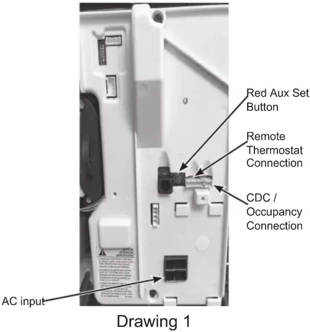
- Insert the Control Card wiring harness into the thermostat connection port on the front of the Zoneline control box cover.
- For Makeup Air Models (*DBM and *EBM), insert the small connector into the mating CDC Connection port next to the thermostat port. (See Drawing 1)
NOTE: If not a Makeup Air Model, DO NOT plug in the CDC/occupancy connection.
Installing the Wireless Control Card (cont.)
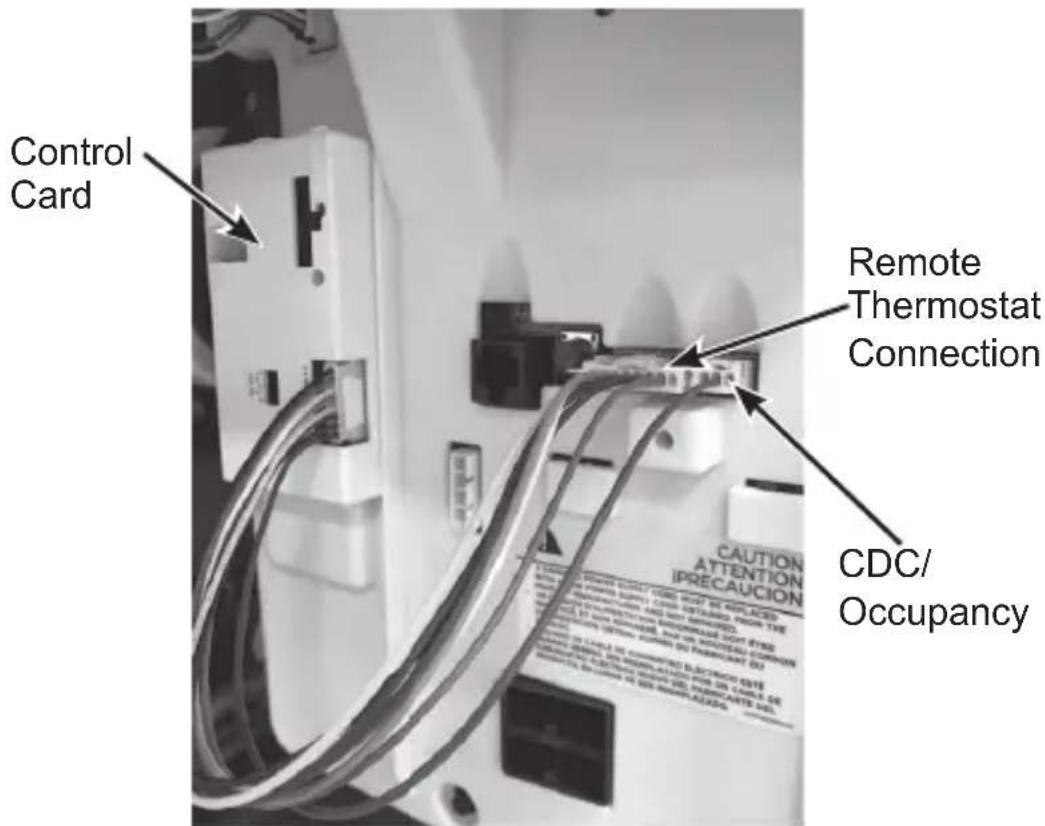
- Using the supplied double sided tape, attach the control card to the Zoneline control box cover. (See Drawing 2) Mount the control card inside of the hvac unit.
The wireless control card antenna must not be touching any metal components of the hvac unit.
The wireless control card antenna must face the thermostat on the wall and be oriented so that any metal parts of the Zoneline do not obstruct the wireless communication to the thermostat and, in case of a network installation, to other wireless control cards and the server.
The wireless control card must not be placed in the Zoneline condensation pan and must be mounted so it cannot fall into the condensation pan.
- For wired applications, join the common and 24VAC wires with any code-approved low voltage field supplied connection method.
Drawing 2
Wiring Table – 24V AC
| Wire Color Terminal Letter Terminal | Connection | |
| Black C Common | ||
| Red R 24V | ||
| Yellow Y Compressor | ||
| White W Heat | ||
| Orange O or B Reversing Valve | ||
| Green GH | Fan High | |
| Purple | GL | Fan Low |
| Brown AUX | Occupancy |
NOTE: If the PTAC unit has only one (1) fan speed, connect both fan control wires – Green and Purple – to the fan terminal (G).
Wireless Installation

Mounting the thermostat to the wall
- Remove the thermostat cover;
- Use the supplied wall anchors and mounting screws to secure the thermostat to the wall;
- Insert two (2) AA-cell batteries (not supplied) into the thermostat battery compartment;
- Follow the “Thermostat Configuration” instructions starting on page 11.
- Replace the thermostat cover and screw in the locking screw.
Wired Installation
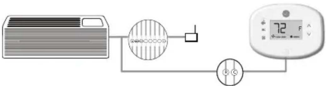
Mounting the thermostat to the wall
- Connect R & C from HVAC unit to the corresponding wires on the harness by splicing 24VAC and common wires from the thermostat into the 24VAC and common wires to the zoneline.
- Remove the thermostat cover;
- Use the supplied wall anchors and mounting screws to secure the thermostat to the wall;
- Follow the “Thermostat Configuration” instructions starting on page 11.
- Replace the thermostat cover and screw in the locking screw.
Thermostat Configuration
Once the thermostat is powered, thermostat configuration settings will appear on the thermostat screen.
In order to properly operate the HVAC unit:
- Set the thermostat clock
- Enter the room number
- Configure the equipment settings
- Select Energy Savings Preset (Zoneline custom settings are the default).
The thermostat configuration screens have a 30-second time-out. If no action is taken within thirty (30) seconds, the thermostat will exit configuration settings.
NOTE: You can access Thermostat Configuration settings at any time by pressing the "Configuration" button.
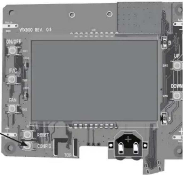
NOTE: If the thermostat is connected to a network, the settings configured online will be applied.
Setting the thermostat clock

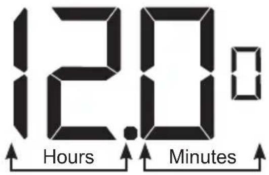
Set the thermostat clock to current time in 24h (Military Time) format.
- Use the "Up" and "Down" buttons to set the hours
- Press the "Fan" button to advance to the minutes setting
- Use the "Up" an "Down" buttons to set the minutes
- Press the "F/C" button to advance to the next menu
Setting the clock correctly is crucial for proper operation of the thermostat.
NOTE: The thermostat clock will need to be reset each time the batteries are replaced.
Entering the room number
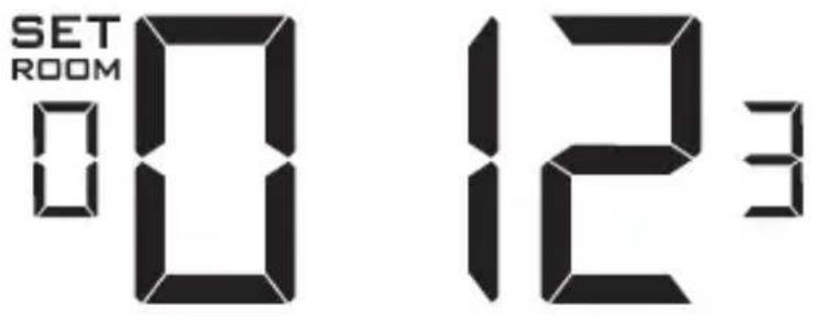
Enter the room number by changing the digits on the screen. Leading zeros “0” preceding other digits will be ignored, i.e. Room number “123” should be entered as “00123”.
- Use the "Up" and "Down" buttons to change the digit;
- Press the "Fan" button to advance to the next digit;
- Press the "F/C" button to advance to the next menu;
Entering the room number correctly is crucial for proper operation of networked systems.
Configuring the Equipment Settings - Compressor Type
SET
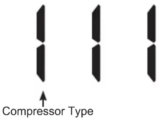
Use the “Up” and “Down” buttons to change the compressor type by changing the first digit
0 - No Compressor
1* - Heat pump
2 - Air Conditioner
- Press the "Fan" button to advance to the next setting;
* Indicates default setting
NOTE: If the Zoneline is an AZ45 model, change the compressor type to a 2.
Configuring the Equipment Settings - Electric Heat
SET
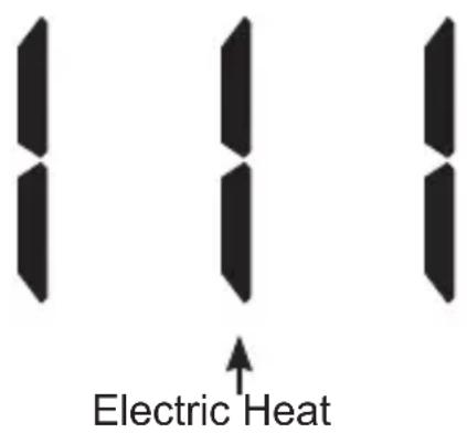
Use the “Up” and “Down” buttons to change the Electric Heat setting by changing the second digit;
0 - No Electric Heat- All Zonelines have Electric heat - Do not select this option.
1* - Electric Heat
- Press the "Fan" button to advance to the next setting;
* Indicates default setting
Configuring the Equipment Settings - Reversing Valve
SET
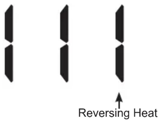
Use the “Up” and “Down” buttons to change the reversing valve type by changing the first digit
0 - OB contact is energized to cool
1* - OB contact is energized to heat (default operation for Zoneline heat pump models)
Refer to the HVAC unit documentation to determine the correct OB VALVE setting.
If incorrect OB VALVE Setting is selected, the HVAC unit will turn on the heating when air conditioning is requested and turn on the air conditioning when heating is requested.
- Press the "F/C" button to advance to the next menu
- Press the "Fan" button to advance to toggle to equipment settings.
* Indicates default setting
NOTE: Zonelines OB is energized in heating mode.
Configuring the Energy Saving Settings

Use the "Up" and "Down" buttons to select the Energy Saving preset:
E-C*: Custom Energy Savings
• Refer to the APPENDIX 1 on page 48 for Energy Saving Preset details.
- For details on changing the custom settings, refer to the "Custom Energy Savings Settings" section on page 19.
E-0: Energy Savings Off - No Temperature Setback;
E-1: Lowest Energy Savings;
E-2: Lower Energy Savings;
E-3: Standard Energy Savings;
E-4: Higher Energy Savings;
E-5: Highest Energy Savings;
- Press the "Power" button to save the Thermostat Configuration and start using the thermostat.
* Indicates default setting
Testing the thermostat
Following the thermostat configuration, test if the thermostat is controlling the Zoneline unit.
- Press the "Power" button to turn the thermostat ON;
- Press the “Down” button to change the temperature set point below the current room temperature to confirm that the thermostat initiates air conditioning.
- Press the “Up” button to change the temperature set point above the current room temperature to confirm that the thermostat initiates heating.
- Change the fan speed by touching the “Fan” button to test if the thermostat is controlling the fan speed.
Custom Energy Savings Settings
This thermostat comes preprogrammed to use a custom energy setting. To change any of these presets, follow the instructions below.
Accessing the Thermostat Settings
With the thermostat turned on, press and hold the "Configuration" button until the first thermostat settings screen appears. The thermostat must be turned on to access the thermostat settings.
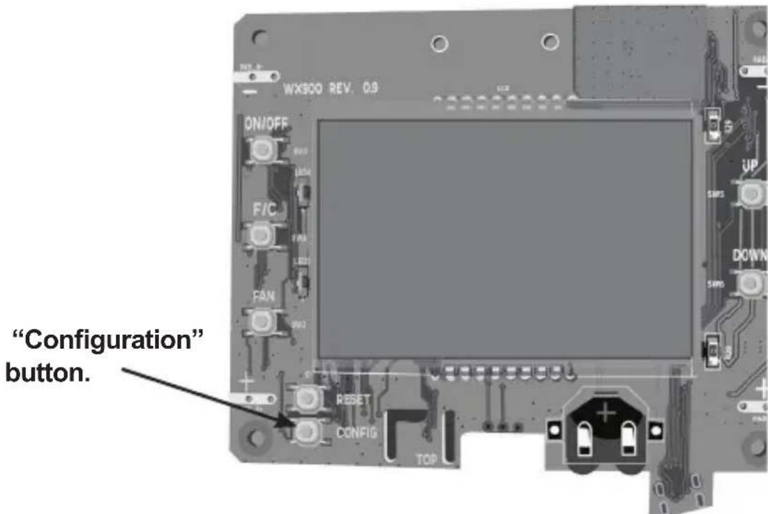
NOTE: If the thermostat is connected to a network, the settings configured online will be applied.
- Use the "Up" and "Down" buttons to change the setting;
- Press the "F/C" button to advance to the next setting;
- Press the "Fan" button to return to the previous setting;
- Press the "Power" button to save and exit thermostat settings.
Using the Thermostat Settings Screens
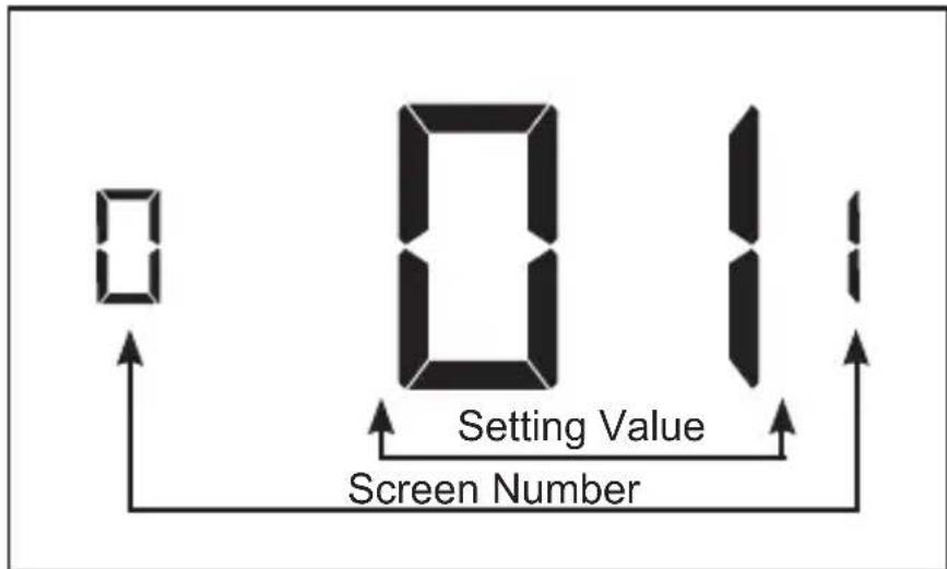
- Use the "Up" and "Down" buttons to change the setting.
- Press the "F/C" button to advance to the next setting.
- Press the "Fan" button to return to the previous setting.
- Press the "Power" button to save and exit thermostat settings.
The above is a representation of how to read the digits on the thermostat screen.
01 - FAN CONTROL MODE
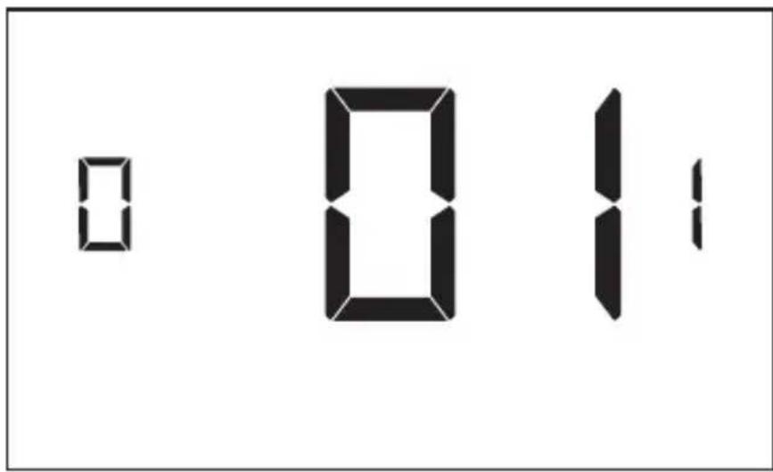
Select Fan Control Mode:
00 - MANUAL - guest can select automatic or continuous fan mode.
01* - AUTOMATIC - fan runs only when there is a demand for heating or air conditioning.
* Indicates default setting.
02 – 1ST STAGE DIFFERENTIAL - HEAT
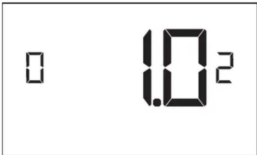
(0.2°F - 3.0°F; 1.0°F* default setting) Select the number of degrees** the thermostat has to sense between the automatic changeover temperature for heat and the room temperature before a call for the 1st stage heating is initiated.
** above the dead band offset (refer to page 40)
03 – 2ND STAGE DIFFERENTIAL - HEAT
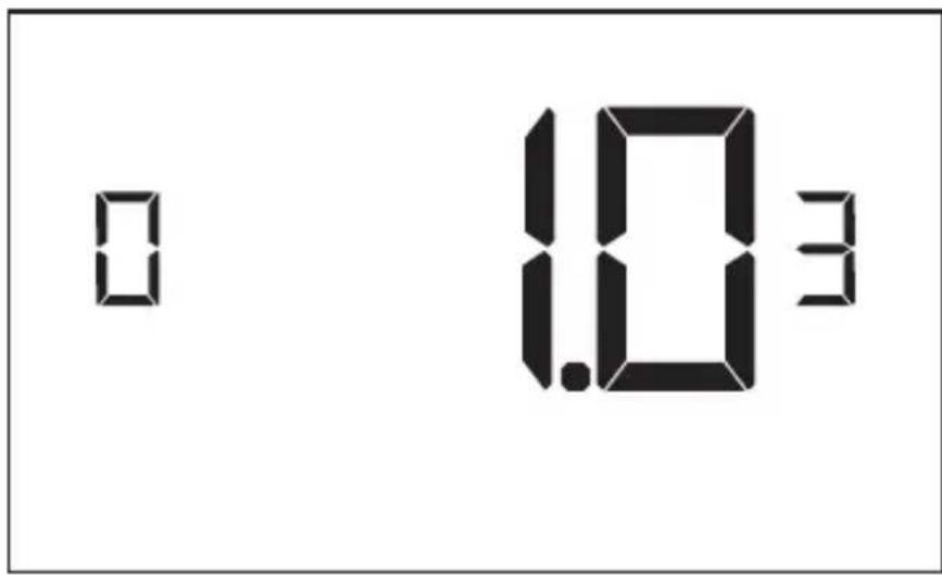
(1.0°F - 2.0°F; 1.0°F* default setting) Select the difference between 1st stage heating and 2nd stage heating initiation.
04 – 1ST STAGE DIFFERENTIAL - COOL
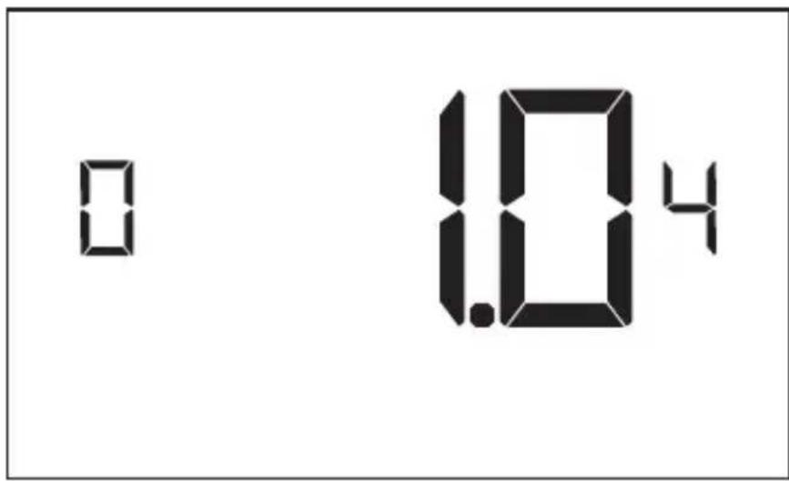
(0.2°F - 3.0°F; 1.0°F* default setting) Select the number of degrees** the thermostat has to sense between the automatic for cool and the room temperature before a call for the 1st stage cooling is initiated.
**below the dead band offset (refer to page 40)**
05 - INCIDENTAL OCCUPANCY THRESHOLD
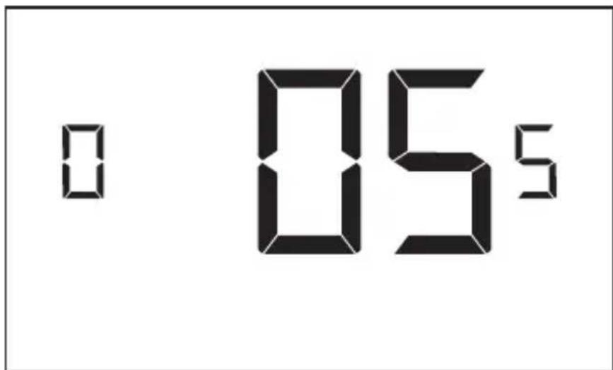
(00 - 60; 05* default setting) Select the minimum period of time (in minutes) for which occupancy needs to be detected to enter the guest occupancy mode.
When occupancy is detected, thermostat will switch to occupied mode for a duration of “Incidental Occupancy Threshold” selected here.
If occupancy is detected for a period of time shorter than the “Incidental Occupancy Threshold” selected here, the thermostat will automatically revert to unoccupied mode at the end of the “Incidental Occupancy Threshold” period and continue to observe energy saving functions that were in effect before the room became occupied. This setting allows ignoring incidental room visits.
If occupancy is detected for a period of time longer than the “Incidental Occupancy Threshold” selected here, the thermostat will enter the guest occupancy mode. When the thermostat is in the guest occupancy mode, it will revert to unoccupied mode and initiate the setback temperature only when occupancy is not detected for the duration of the setback delay (Heat or Cool) period.
06 – NIGHT OCCUPANCY THRESHOLD

(00 - 60; 01* default setting) Select the minimum period of time (in minutes) for which occupancy needs to be detected in order to consider the room occupied during the “Night Occupancy” period.
When occupancy is detected during the “Night Occupancy Period” for longer than the “Night Occupancy Threshold” selected here, the thermostat will instantaneously switch to occupied mode.
If occupancy is detected for a period of time shorter than the “Night Occupancy Threshold” selected here, the thermostat will automatically revert to unoccupied mode and continue to observe energy saving functions that were in effect before the room became occupied.
If occupancy is detected for a period of time longer than the “Night Occupancy Threshold” selected here, the thermostat will disable the occupancy sensor and consider the room occupied until the end of the “Night Occupancy” period.
This feature ensures that energy saving functions that may affect guest comfort will not come in effect during the "Night Occupancy" period.
07 - FORCED 2ND STAGE HEATING
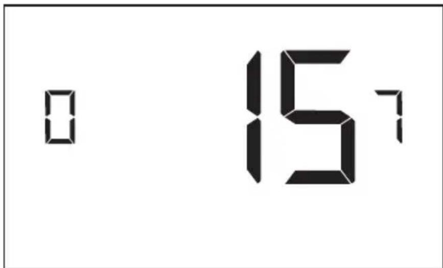
(00 - 60; 15* default setting) Select a number of minutes 1st stage heating will run before 2nd stage heating is automatically initiated if the guest set point is not reached and the 2nd stage heating is not initiated through differential settings.
This feature allows automatically turning on 2nd stage heating to avoid excessive compressor use.
Set to 00 to disable the feature.
08 – NIGHT OCCUPANCY START
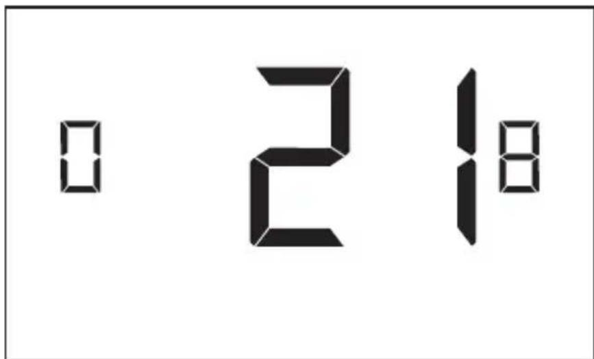
(00 - 23; 21* default setting) Select the start time (in hours - 24-hour clock) for "Night Occupancy"
If occupancy is detected for a period of time longer than the “Night Occupancy Threshold” during “Night Occupancy” period, the thermostat will disable the occupancy sensor and consider the room occupied until the end of the “Night Occupancy” period.
This feature ensures that energy saving functions that may affect guest comfort will not come in effect during the “Night Occupancy” period if room was occupied for a period of time longer than “Night Occupancy Threshold”.
09 – NIGHT OCCUPANCY END
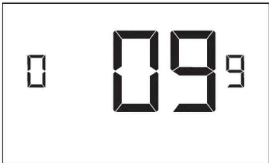
(00 - 23; 09* default setting) Select the time (in hours - 24-hour clock) for "Night Occupancy" to end.
This is the time of day the “Night Occupancy” ends and the thermostat switches back to the room sensing settings chosen in the other occupancy modes.
10 - TEMPERATURE RECOVERY TIME
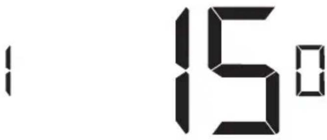
(00 - 60; 15* default setting) Select the maximum time allowed for a HVAC unit to attain temperature as defined by Heat and Cool “Recovery Temperature”.
"Temperature Recovery Time" selected here and the actual temperature recovery ability of the HVAC unit are used to calculate setback temperatures. Calculated setback temperatures maximize energy savings and at the same time ensure that a comfortable room temperature (defined as Heat and Cool "Recovery Temperature") will be restored within the selected "Temperature Recovery Time".
Setting the “Temperature Recovery Time” to “00”, disables temperature recovery. When temperature recovery is disabled, thermostat will use the Minimum and Maximum Setback Temperatures as setback set points.
11 - RECOVERY TEMPERATURE - HEAT
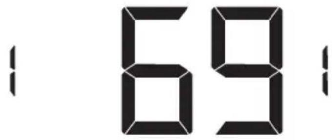
(62°F - 82°F; 69°F* default setting) Select the room temperature in °F that a HVAC unit will have to attain within the selected “Temperature Recovery Time” when there is a need for heating.
12 - TEMPERATURE SETBACK DELAY - HEAT
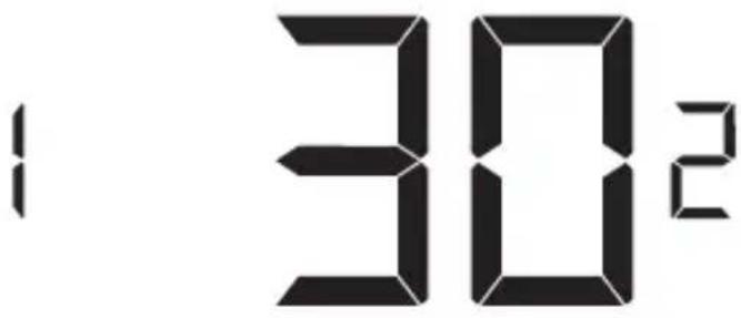
(00 - 120; 30* default setting) Select the time delay (in minutes) for which the room that is in the guest occupancy mode needs to be unoccupied before the temperature setback is initiated.
This feature prevents initiating temperature setback prematurely while the guest is still in the room but in an area where occupancy cannot be detected by the occupancy sensor.
Setting the "Temperature Setback Delay - Heat" to "00", disables the setback in the heat mode.
13 - MINIMUM SETBACK TEMPERATURE - HEAT
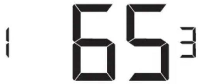
(52°F - 72°F; 65°F* default setting) Select the "Minimum Setback Temperature" in °F.
Setback temperature is calculated by measuring HVAC unit's ability to attain "Recovery Temperature - Heat" within "Temperature Recovery Time".
If recovery is disabled (“Temperature Recovery Time” is set to “0”) or if setback temperatures have not yet been calculated, the “Minimum Setback Temperature” value will be used as the setback temperature for heating.
If calculated setback temperature for heating is lower than “Minimum Setback Temperature”, then the “Minimum Setback Temperature” will be used as setback temperature for heating.
This feature allows defining the minimum temperature in a room when room is unoccupied and the thermostat is in the setback mode.
14 - TEMPERATURE SETBACK DELAY - COOL
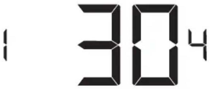
(00 - 120; 30* default setting) Select the time delay (in minutes) for which the room that is in the guest occupancy mode needs to be unoccupied before the temperature setback is initiated.
This feature prevents initiating temperature setback prematurely while the guest is still in the room but in an area where occupancy cannot be detected by the occupancy sensor.
Setting the "Temperature Setback Delay - Cool" to "00", disables the setback in the cool mode. Set to "00" to disable EMS.
15 - MAXIMUM SETBACK TEMPERATURE - COOL
1765
(72°F - 92°F; 76°F* default setting) Select the "Maximum Setback Temperature" in °F.
Setback temperature is calculated by measuring HVAC unit's ability to attain "Recovery Temperature - Cool" within "Temperature Recovery Time".
If recovery is disabled (“Temperature Recovery Time” is set to “0”) or if setback temperatures have not yet been calculated, the “Maximum Setback Temperature” value will be used as the setback temperature for cooling.
If calculated setback temperature for air conditioning is higher than “Maximum Setback Temperature”, then the “Maximum Setback Temperature” will be used as setback temperature for air conditioning.
This feature allows defining the maximum temperature in a room when room is unoccupied and the thermostat is in the setback mode.
16 - RECOVERY TEMPERATURE - COOL
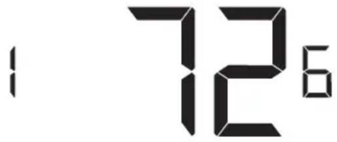
(62°F - 82°F; 72°F* default setting) Select the room temperature in °F that a HVAC unit will have to attain within the selected “Temperature Recovery Time” when there is a need for air conditioning.
17 - MINIMUM SET POINT
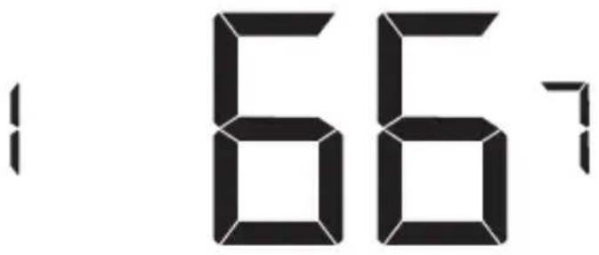
(64°F - 84°F; 66°F* default setting) Select the minimum set point in °F that a guest can select.
18 - MAXIMUM SET POINT
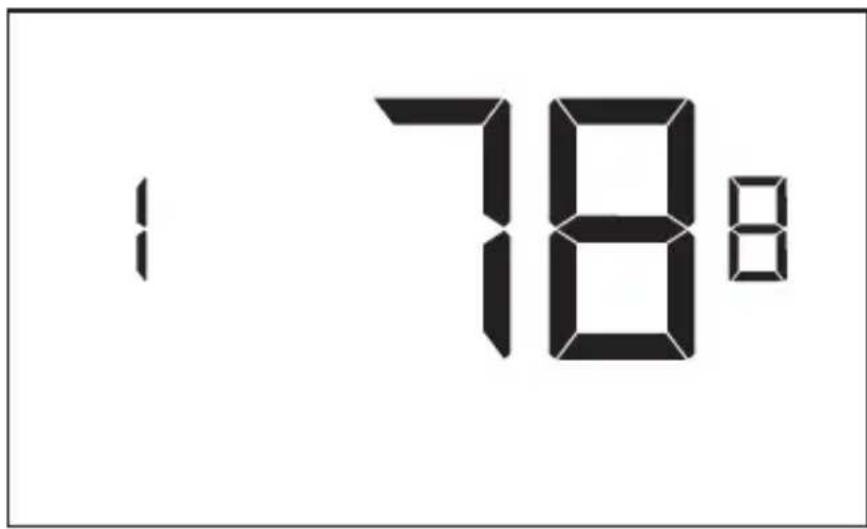
(60°F - 82°F; 78°F* default setting) Select the maximum set point in °F that a guest can select.
19 – TEMPERATURE CONTROL MODE
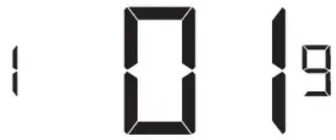
Select Temperature Control Mode:
00 - MANUAL - Allows users to select HEAT only or COOL only temperature control mode to maintain the room temperature.
01* - AUTOMATIC - Thermostat automatically turns on heating or air conditioning to maintain the room temperature at the selected temperature set point.
* Indicates default setting
20 – AUTO CHANGEOVER SET POINT OFFSET (DEAD BAND)
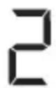
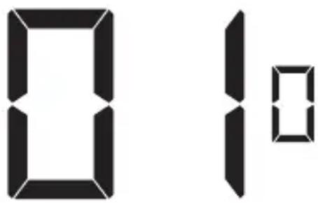
(00°F - 04°F; 01°F* default setting) Select the difference between the guest-selected set point and the heat and the cool set point when the thermostat is in the automatic temperature control mode.
This value plus the 1st stage differential defined in steps 02 and 04, defines the temperature at which the thermostat would automatically change heating/cooling modes.
This feature allows adjusting the dead band between the heat and the cool set points in automatic changeover mode in order to avoid the system from bouncing back and forth between heating and cooling under normal operating conditions.
21 - SETBACK SET POINTS / AUTO-RESTORE
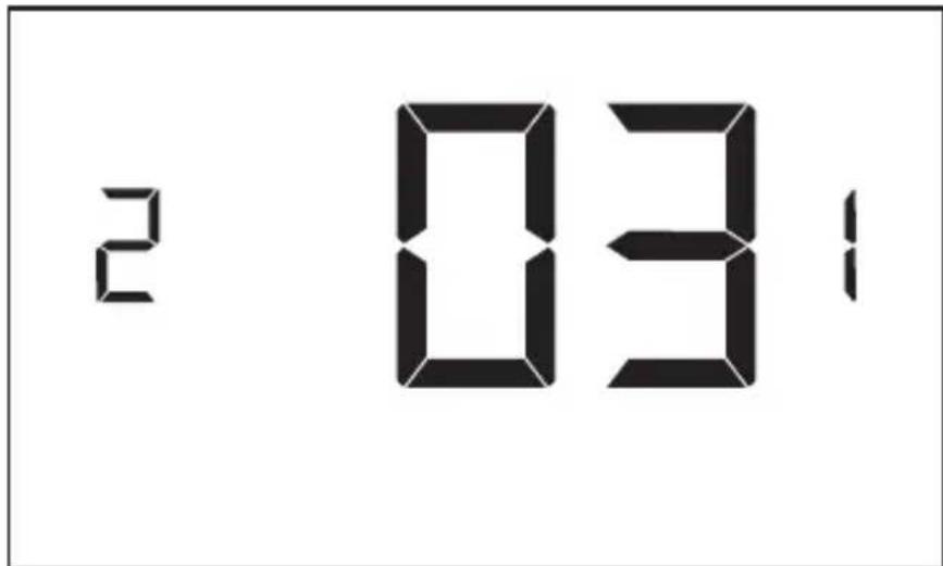
Select Temperature Control Mode:
00 - When room is unoccupied and the thermostat is in the setback mode or turned off, it will NOT maintain the temperature between heat and cool setback set points. When guest enters the room, the thermostat will be turned off - it will not automatically restore the most recent guest settings.
01 - When room is unoccupied and the thermostat is in the setback mode or turned off, it will maintain the temperature between heat and cool setback set points.
When guest enters the room, the thermostat will be turned off - it will not automatically restore the most recent guest settings.
02 - When room is unoccupied and the thermostat is in the setback mode or turned off, it will NOT maintain the temperature between heat and cool setback set points. When guest enters the room, the thermostat will automatically restore the most recent guest settings.
03* - When room is unoccupied and the thermostat is in the setback mode or turned off, it will maintain the temperature between heat and cool setback set points. When guest enters the room, the thermostat will automatically restore the most recent guest settings.
* Indicates default setting
22 - AUTOMATIC HUMIDITY CONTROL
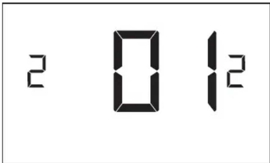
00 - Disable automatic humidity control
01* - Enable automatic humidity control
When “Automatic Humidity Control” is enabled, thermostat will turn on air conditioning in an unoccupied room when humidity raises above 60% and room temperature is above 72°F until either room humidity is below 55% or room temperature is below 72°F.
* Indicates default setting
23 - TEMPERATURE CALIBRATION
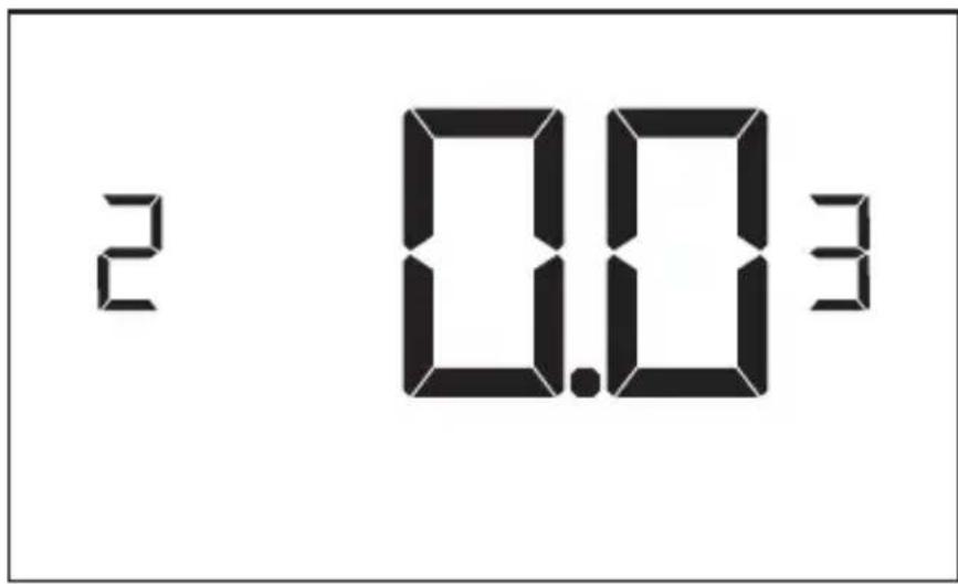
(-5.0°F - 5.0°F; 0.0°F* default setting) Calibrate the temperature display: +/- 5.0°F
Replacing Thermostat Batteries
The low battery indicator will be displayed on the thermostat screen when it is necessary to replace batteries in the thermostat.
Under normal operating conditions, new brand-name alkaline batteries will last for a period of approximately one (1) year.
Please replace batteries every twelve (12) months to ensure continuous thermostat operation.
To replace thermostat batteries:
- Remove the thermostat cover;
- Replace the two (2) AA-cell batteries (not-supplied);
- Replace the thermostat cover;
- Follow the “Thermostat Configuration” instructions to set the thermostat clock;
- Press the "Power" button to start using the thermostat;
NOTE: The thermostat maintains all the “Thermostat Configuration” settings in a non-volatile memory. There is no need to configure the thermostat again after battery replacement.
NOTE: While batteries are not required in a wired installation, batteries should be installed to prevent re-configuring the time on the thermostat if a power failure occurs.
Error Codes
ERR1 - Thermostat Temperature Sensor Hardware Defect
ERR2 - Thermostat Radio Hardware Defect
ERR3 - Thermostat Radio Software Defect
ERR4 - No link with the Wireless Control Card
ERR5 - Thermostat Memory Defect
NOTES:
For ERR1, ERR2, ERR3, and ERR5, call GE Appliances service. (Phone number located in Limited Warranty section on page 50.
For ERR4, reset the configurations starting on page 5.
The thermostat is not controlling the HVAC unit.
Check if the HVAC unit is set to “External Thermostat” (Class 2) mode. Refer to Zoneline Owner’s Manual, Aux settings.
Verify the status of the red light on the Wireless Control Card.
- The red light is off
The Wireless Control Card is not powered. Verify that the Wireless Control Card is properly wired to the HVAC unit-specifically make sure that the RED and the BLACK wire are properly connected.
- If the red light is blinking with one (1) flash.
The Wireless Control Card is powered but it is not communicating with the thermostat, turn the thermostat off and on to re-initiate the linking procedure.
In case of a Network Installation, re-link the thermostat and the Wireless Control Card with the Network Programmer.
- The red light is blinking with three (3) flashes.
The Wireless Control Card is communicating with the thermostat. Verify that the Wireless Control Card is properly wired to the HVAC unit and that equipment settings on a thermostat - compressor type, electric heat and reversing valve - are properly configured.
Initiating a Master Reset
If there are reported errors or configuration issues, the user may master reset the thermostat to its default parameters.
Procedure:
- Remove the faceplate of the thermostat
- Power down the thermostat by either removing the batteries or cutting power to the thermostat.
- While the thermostat is powered off, press and hold the "config" button located on the control board inside the thermostat.
- Restore power to the thermostat by reinstalling the battieries.
- Once the screen lights up, release the "config" button.
- If the master reset was successful, the thermostat will display “12:00”, indicating all settings will be reset to default and the thermostat needs to be re-configured. Please see “configuring thermostat” in the manual on page 9.
Contact GE Appliances technical support at 1-844-GE4-PTAC (or 844-434-7822) if the issues are not resolved.
Appendix 1 - Energy Saving Presets
| Screen # Energy Level Default | Setting | |||||||
| 0 | 1 | 2 | 3 | 4 | 5 | E | ||
| 01 Fan | Control Mode Auto Auto Auto | Auto Auto | Auto Auto | Auto | ||||
| 02 | 1st Stage Differential Heat | 0.5 | 0.5 | 0.5 | 0.5 | 0.5 | 0.5 | 1.0 |
| 03 2nd | Stage Differential Heat | 1.0 1.0 | 1.0 2.0 | 2.0 2.0 | 1.0 | |||
| 04 | 1st Stage Differential Cool | 0.5 | 0.5 | 0.5 | 0.5 | 0.5 | 0.5 | 1.0 |
| 05 Guest | Occupancy Threshold | 00 | 05 | 05 | 05 | 05 | 05 | 05 |
| 06 Night | Occupancy Threshold | 01 | 01 | 01 | 01 | 01 | 01 | 01 |
| 07 Force | 2nd Stage Heating After | 30 | 30 | 30 | 30 | 30 | 30 | 15 |
| 08 | Night Occupancy Start | 18 | 19 | 20 | 21 | 22 | 23 | 21 |
| 09 | Night Occupancy End | 12 | 11 | 10 | 9 | 8 | 7 | 09 |
| 10 | Recovery Time | 00 | 15 | 20 | 25 | 30 | 00 | 15 |
| 11 Recovery Temperature Heat | 70 | 69 | 68 | 67 | 66 | 65 | 69 | |
| 12 | Setback Delay - Heat | 00 | 30 | 25 | 20 | 15 | 10 | 30 |
| 13 Minimum Setback Temperature | 67 | 66 | 65 | 64 | 63 | 62 | 65 | |
| 14 | Setback Delay - Cool | 00 | 30 | 25 | 20 | 15 | 10 | 30 |
| 15 Maximum Setback Temperature | 72 | 74 | 76 | 78 | 80 | 82 | 76 | |
| 16 Recovery Temperature Cool | 71 | 72 | 73 | 74 | 75 | 76 | 72 | |
| 17 | Minimum Set point | 64 | 64 | 65 | 66 | 67 | 68 | 66 |
| 18 | Maximum Set point | 82 | 82 | 80 | 78 | 76 | 74 | 78 |
| 19 Temperature Control Mode | Auto Auto Auto | Auto Auto Auto | ||||||
| 20 Auto Changeover Set Point | 01 | 01 | 01 | 01 | 01 | 01 | 01 | |
| 21 Setback Set Points / Auto Restore | OFF | ON ON | ON ON | ON ON | ||||
| 22 Automatic Humidity Control | ON ON | ON ON | ON | ON ON | ||||
| 23 Temperature Calibration 0.0 | 0.0 0.0 0.0 0.0 0.0 | |||||||
Technical Specifications
| Thermostat Wireless Control Card | ||
| Case Dimensions (Imperial) 4.015 x 5.5118" x 0.925" 3.875" | x 2.125" x 0.75" | |
| Case Dimensions (Metric) 102mm x 140mm x 23.5mm | 98mm x 54mm x 19mm | |
| Screen Dimensions (Imperial) 3.625" x 2.125" N/A | ||
| Screen Dimensions (Metric) 92mm x 54mm N/A | ||
| Operating Voltage 3V DC - 2 "AA" Cell Batteries OR(Optional) 24V AC/DC | 24V AC/DC | |
| Control Outputs Fan High (GH) | ||
| Fan Low (GL) | ||
| Compressor (Y) | ||
| Heat Pump (OB) | ||
| Electric Heat (W2) | ||
| Occupancy Out (AUX) | ||
| Occupancy Sensor Beam Width | ±47° (94°) N/A | |
| Wireless Frequency 900MHz 900MHz | ||
| Temperature Accuracy | ±1°F | N/A |
| FCC ID | XEYWX | XEYV8ACCC |

FCC STATEMENT
This device complies with part 15 of the fcc rules. Operation is subject to the following two conditions: (1) this device may not cause harmful interference, and (2) this device must accept any interference received, including interference that may cause undesired operation.
Pursuant to part 15.21 of the FCC rules, any changes or modifications to this equipment not expressly approved by GE Appliances may void the user's authority to operate the equipment.
THERMOSTAT LIMITED WARRANTY
Staple your receipt here.
Proof of the original purchase date is needed to validate the warranty.
For The Period Of: GE Appliances Will Replace:
One Year Full Replacement of the thermostat which fails
From the date of the due to a defect in materials or workmanship.
original purchase
For help with thermostat troubleshooting, call 1-844-GE4-PTAC
(or 844-434-7822)
What GE Appliances Will Not Cover:
■ Service trips to your location.
- Improper installation. If you have an installation problem, contact your installer. You are responsible for providing adequate electrical connections to the product.
- Failure of the product resulting from modifications to the product or due to unreasonable use, including failure to provide reasonable and necessary maintenance.
In commercial locations, labor necessary to move the unit, after it has been initially installed, to a location where it is accessible for service by an individual technician; or, if the instructions included in this manual have been disregarded.
■ Replacement of location fuses or the resetting of circuit breakers.
■ Damage to the product caused by improper power supply voltage, accident, fire, floods or acts of God.
■ Incidental or consequential damage caused by possible defects with this thermostat.
EXCLUSION OF IMPLIED WARRANTIES—Your sole and exclusive remedy is product exchange as provided in this Limited Warranty. Any implied warranties, including the implied warranties of merchantability or fitness for a particular purpose, are limited to one year or the shortest period allowed by law.
This limited warranty is extended to the original purchaser and any succeeding owner for products purchased for use within the USA and Canada. In Alaska, the limited warranty excludes the cost of shipping or service calls to your site.
Some states or provinces do not allow the exclusion or limitation of incidental or consequential damages. This limited warranty gives you specific legal rights, and you may also have other rights which vary from state to state or province to province. To know what your legal rights are, consult your local, state or provincial consumer affairs office or your state's Attorney General.
Warrantor: GE Appliances, Louisville, KY 40225
- OWNER'S MANUAL & INSTALLATION INSTRUCTIONS
- THANK YOU FOR MAKING GE APPLIANCES A PART OF YOUR HOME.
- Table of Contents
- Safety Information 4
- Before You Begin....5
- Thermostat Installation 7
- Thermostat Configuration....11
- Custom Energy Savings Settings.... 19
- Thermostat Maintenance....44
- Troubleshooting 45
- Appendix 1 - Energy Saving Presets ......48
- Technical Specifications....49
- Limited Warranty 50
- IMPORTANT SAFETY INFORMATION READ ALL INSTRUCTIONS BEFORE USING
- WARNING
- FIRE AND SHOCK HAZARD
- NOTICE
- Specifications.
- System Configurations:
- Installing the Wireless Control Card
- Installing the Wireless Control Card (cont.)
- Wireless Installation
- Mounting the thermostat to the wall
- Wired Installation
- Thermostat Configuration
- Setting the thermostat clock
- Entering the room number
- Configuring the Equipment Settings - Compressor Type
- Configuring the Equipment Settings - Electric Heat
- Configuring the Equipment Settings - Reversing Valve
- Configuring the Energy Saving Settings
- Testing the thermostat
- Custom Energy Savings Settings
- Accessing the Thermostat Settings
- NOTE: If the thermostat is connected to a network, the settings configured online will be applied.
- Using the Thermostat Settings Screens
- - FAN CONTROL MODE
- - INCIDENTAL OCCUPANCY THRESHOLD
- – NIGHT OCCUPANCY THRESHOLD
- - FORCED 2ND STAGE HEATING
- – NIGHT OCCUPANCY START
- – NIGHT OCCUPANCY END
- - TEMPERATURE RECOVERY TIME
- - RECOVERY TEMPERATURE - HEAT
- - TEMPERATURE SETBACK DELAY - HEAT
- - MINIMUM SETBACK TEMPERATURE - HEAT
- - TEMPERATURE SETBACK DELAY - COOL
- - MAXIMUM SETBACK TEMPERATURE - COOL
- - MINIMUM SET POINT
- – TEMPERATURE CONTROL MODE
- – AUTO CHANGEOVER SET POINT OFFSET (DEAD BAND)
- - SETBACK SET POINTS / AUTO-RESTORE
- - AUTOMATIC HUMIDITY CONTROL
- - TEMPERATURE CALIBRATION
- Replacing Thermostat Batteries
- Error Codes
- NOTES:
- The thermostat is not controlling the HVAC unit.
- Initiating a Master Reset
- Procedure:
- Technical Specifications
- FCC STATEMENT
- THERMOSTAT LIMITED WARRANTY
- For The Period Of: GE Appliances Will Replace:
- What GE Appliances Will Not Cover:
Brand : GE
Model : RAK180W1
Category : Thermostat