
CLUB-MATRIX - Lighting AFX - Free user manual and instructions
Find the device manual for free CLUB-MATRIX AFX in PDF.

| Product type | Professional LED lighting |
| Brand | AFX |
| Model | CLUB-MATRIX |
| Light source | 60 RGB 3 W LEDs |
| Power supply | 90-240 V~, 50/60 Hz |
| Dimensions (L x W x H) | 265 x 213 x 117 mm |
| Weight | 2.18 kg |
| Beam angle | 26° |
| DMX channels | 11 or 29 channels |
| Operating modes | Automatic, DMX, Master/Slave, Music control, Remote control |
| Connectors | Powercon (input/output), XLR 3-pin DMX |
| Protection class | I (mandatory grounding) |
| Usage | Indoor only |
| Minimum safety distance | 0.5 m |
| Max ambient temperature | 40 °C |
| Max housing temperature | 85 °C |
| Max operating time | 8 consecutive hours |
| Remote control | Infrared, CR2025 battery, range 6 m |
| Cleaning | Soft cloth and glass cleaner, vacuum inside once a year |
| Repairability | Light source non-replaceable, repair by professional |
| Fuse | Yes, replaceable with identical one |
| Compliance | CE |
| Box contents | Unit, remote control, power cord, DMX cable, user manual |
Frequently Asked Questions - CLUB-MATRIX AFX
User questions about CLUB-MATRIX AFX
0 question about this device. Answer the ones you know or ask your own.
Ask a new question about this device
Download the instructions for your Lighting in PDF format for free! Find your manual CLUB-MATRIX - AFX and take your electronic device back in hand. On this page are published all the documents necessary for the use of your device. CLUB-MATRIX by AFX.
USER MANUAL CLUB-MATRIX AFX
natural_image
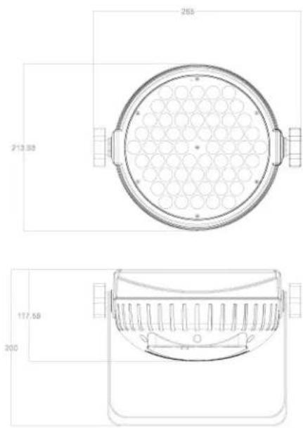
Technical line drawing of a circular industrial component mounted on a stand (no text or symbols)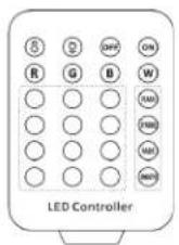
GB - User Manual - p. 2
- 60x 3W RGB LED
- Matrix function
• 11/29 DMX channels - Auto, DMX, master-slave, music and remote controlled operation
• Powercon in-/outputs
• IR remote control included
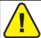
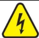
EXPLANATION OF SYMBOLS

The triangle containing a lightning symbol is used to indicate whenever your health is at risk (due to electrocution, for example).

An exclamation mark in a triangle indicates particular risks in handling or operating the appliance.

The unit complies with UK standards

For indoor use only

Protection class I. Requires an earth connection

Minimum distance between the appliance and other objects

Don't stare into the light beam
CAUTION DO NOT OPEN THE HOUSING SHOCK HAZARD
SAFETY RECOMMENDATIONS
- Please read these instructions carefully, they include important information about the installation, usage and maintenance of this product.
- Please keep this User Guide for future reference.
- Always make sure that you are connecting to the proper voltage, and that the line voltage you are connecting to is not higher than that stated on the bottom of the fi xture.
- The appliance is part of class I and must exclusively connected to an earthed mains outlet.
- This product is intended for indoor use only!
- To prevent risk of fire or shock, do not expose fixture to rain or moisture. Make sure there are no flammable materials close to the unit while operating.
- The unit must be installed in a location with adequate ventilation, at least 20in (50cm) from adjacent surfaces. Be sure that no ventilation slots are blocked.
- The minimum distance luminaire from that part of the luminaire or lamp to the lighted object is 0.5m.
- The max. ambient temperature (Ta) is 40^ . Don't operate the fixture at higher temperatures.
- The surface temperature of the unit may reach up to 85°C. DO NOT TOUCH the housing bare-hand during its operation. Turn off the power and allow about 20 minutes for the unit to cool down before replacing or servicing.
- DO NOT OPEN the unit within 5 minutes after switching off.
- In the event of a serious operating problem, stop using the unit immediately. Never try to repair the unit by yourself. Repairs carried out by unskilled people can lead to damage or malfunction. Please contact the nearest authorized technical assistance center. Always use the same type of spare parts.
-
Make sure the power cord is never crimped or damaged.
-
Avoid direct eye exposure to the light source while it is on as sensitive persons may suffer an epileptic shock (especially meant for epileptics)!
- The product is for decorative purposes only and not suitable as a household room illumination.
- If the external flexible cable or cord of this luminaire is damaged, it shall be exclusively replaced by the manufacturer or his service agent or a similar qualified person in order to avoid a hazard.
- The lenses, housing or ultraviolet filter must be replaced if they are visibly damaged.
- Please note that the lamp of this device cannot be replaced. If the lamp is faulty, the unit must be discarded
DISCONNECT DEVICE
Please note that the unit DOES NOT have an ON/OFF switch. Please unplug the unit to remove complete the power from the internal circuits before cleaning or servicing. Therefore, the disconnect device shall remain readily accessible.
INSTALLATION
The unit should be mounted via its screw holes on the bracket. Always ensure that the unit is firmly fixed to avoid vibration and slipping while operating. Always ensure that the structure to which you are attaching the unit is secure and is able to support a weight of 10 times of the unit's weight.
The installation must always be secured with a secondary safety attachment, e.g. an appropriate safety rope.
Never stand directly below the device when mounting, removing or servicing the fixture.
POWER SUPPLY AND SIGNAL CABLE CONNECTION
1. Mains Power connection
The exclusive plug should be used between the connection of unit and power. Please ensure that the rated voltage and frequency are accordance with the power supply. The required input voltage and frequency are: 90-240V\~50/60Hz
We suggest that every light has an independent switch so that you can turn on or turn off the light randomly.
Note: the ground wire (yellow/green double-colour wire) must be safely connected, the electrical installation must be in accordance with the related standards
CAUTION: When installing the device, make sure there is no highly inflammable material within a distance of min.5m!
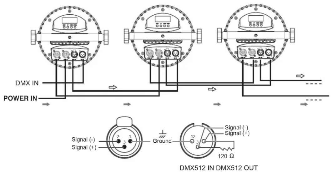
2. Connection of Signal Cable
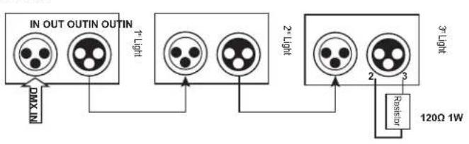
You can use the 3-pin XLR cable to connect the output socket of the master and the input socket of the slave light. Connect the DIGITAL OUT socket of the master and the IN socket of the slave light, then, connect the OUT socket to the IN socket of the next light. Ordinal to connect all the lights as below:
flowchart
graph TD
    A["IN OUT OUTIN OUTIN"] --> B["Light"]
    B --> C["2-LIGHT"]
    C --> D["3-LIGHT"]
    D --> E["Resistor"]
    E --> F["120Ω 1W"]
    G["Max N"] --> A
    H["2-LIGHT"] --> C
    I["Resistor"] --> D
The connection between the output of master and input of product, it's available to use the 3 pins XLR cable which provided by the manufacturer. Signal cable from the DMX output of the controller to the input of the first master light, and connect to the DMX input of second slave light from the DMX output of the first master light, analogously, till connected all the slave lights, and insert the last connector to the output of the final light. (Notice: the diameter of core of every cable should be 0.5mm at least, double core shelter cable should be used). The signal connecting must use the attached 3 pins XLR cable. Notice, all the internal lead wire of the 3 pins XLR cable should not touch to each other or connect to the connector.
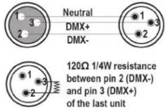
A DMX signal terminator is recommended on the last unit of the chain. DMX terminator is a XLR connector with a 120Ω resistor between the pin 2 and pin 3 of the XLR connector
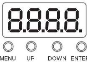
CONTROL PANEL
Use Menu button to choose a function among MODE, SET, DMX, REST, TEST and TEMP. Press Enter button to enter in the menu of the selected function
Use Up and Down button to select the parameters then press Enter button to set the selected parameter
Check the following function table :
| MENU DESCRIPTION | |||||
| MODE | ADDR VALU A001~A XXX (AXXX) DMX address setting | ||||
| SLAV Stand-alone mode | |||||
| AUTO | IP1-8 | ALON /(AU-A) | SP_1~SP_5 (Speed) | Internal programme (alone) | |
| MAST /AU-M) | SP_1~SP_5 (Speed) | Auto-run (Master) | |||
| SOUN | IP1-7 | ALON (SO-A) | Sound setting (alone) | ||
| MAST/(SO-M) | Sound setting (Master) | ||||
| SET | MIC | M-XX Mic sensitivity setting | |||
| LODA | ON/OFF | Reload data | |||
| VER | V-2.0 | Software version | |||
| CALI | Code (password: 088) | Input password | |||
| CH03-CH06 | Calibration | ||||
| SSET | WD | Wired DMX input | |||
| DMX | CH29 | 29CH | |||
| CH11 | 11CH | ||||
| REST | ON/OFF | Total reset | |||
| TEST | CXXX | 000-255 | Manual channel control | ||
| TEMP | TXXX | Current temperature | |||
DMX channel chart: please refer to LAST page
IR REMOTE CONTROLLER
Please operate the remote control within a distance of 6m and 30^ between the remote and the appliance. Aim the remote at the sensor. Remove all obstacles between the remote and the sensor.
The remote control might not work properly if the sensor is exposed to strong sunshine.
If the remote control doesn't work properly, please check the batteries.
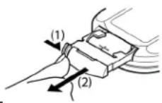
INSTALLING THE BATTERIES IN THE REMOTE CONTROL
- Place the remote face down on a flat surface.
- Push the compartment cover into the direction of the arrow.
- Slide the battery compartment open.
- Remove the old battery and install the new one (CR2025) with the plus (+) symbol facing up.
- Gently slide the battery compartment closed. It locks automatically.
RECOMMENDATIONS FOR BATTERIES

This symbol indicates that used batteries should not be disposed of with household waste but deposed correctly in accordance with your local regulations..
Batteries shall not be exposed to excessive heat such as sunshine, fire or the like.
When the internal batteries are not to be used, remove them to avoid damage caused by battery leakage or corrosion.
ATTENTION: Danger of explosion if battery is incorrectly placed. Only replace by the same or equivalent type.
WARNING : Do not swallow the battery. Danger of chemical burns. Keep new and old batteries out of the reach of children
If the battery compartment doesn't close properly, stop using the product and keep it out of the reach of children.
If you are in doubt whether the batteries have been swallowed or introduced into any other part of the body, contact immediately a doctor.
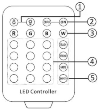
REMOTE CONTROL
NOTE: PLEASE SET THE UNIT TO MODE -> ADDR, OTHERWISE THE REMOTE CONTROL WILL NOT WORK
- BRIGHTNESS & SPEED adjustment: Press brightness and speed in programme mod
or to set the
- ON/OFF of the LEDs.
- SELECT BASIC COLOR: Red, Green, Blue or White (R+G+B)
- COLOUR BUTTONS: For constant lighting of all LEDs in one colour, press the corresponding button.
- SELECTING AN INTERNAL PROGRAMME:
Flash: Colour switch
Strobe: Colour strobe
Fade: Colour fade
Smooth: Colour switch and strobe
CLEANING AND USING FREQUENCY OF PRODUCT
Please make sure that the light is power off before dismantling or maintaining, it's very important to keep the light clean. Frequent cleaning will ensure maximum brightness output, but also prolong the life time. It's suggested to use the high quality, professional glass detergent and soft cloth to clean the light. It's not allowed to use alcohol or chemical solvent. The inner part of the light should be cleaned by vacuum cleaner at least once a year. When the light doesn't work, please check if the fuse is burnt out or not. If it is, the same fuse should be replaced, find out the faulty and restart the light. But please note the repair must be handled by professional.
PHOTOMETRIC DIAGRAM
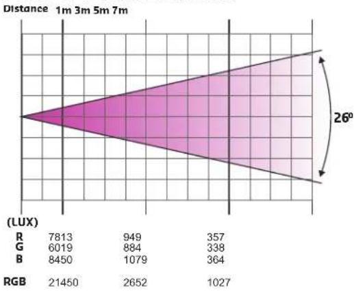
area
| | 1m | 3m | 5m | 7m | | ------ | ---- | ---- | ---- | ---- | | R | 7813 | 949 | 357 | | | G | 6019 | 884 | 338 | | | B | 8450 | 1079 | 364 | | | RGB | 21450| 2652 | 1027 | |TECHNICAL SPECIFICATIONS
Power Supply 90-240V\~50/60Hz
Consumption 180W
Light source 60 x 3W RGB LED
Beam angle 26°
Dimensions....265 x 213 x 117mm
Weight 2.18kg

IMPORTANT NOTE: Electric products must not be put into household waste. Please bring them to a recycling centre. Ask your local authorities or your dealer about the way to proceed.
MANUEL D'UTILISATION
DESCRIPTION
DISPOSITIF DE COUPURE
Consommation....180W
Source lumineuse....60 LED RGBW de 3W
PHOTOMETRISCHES DIAGRAMM
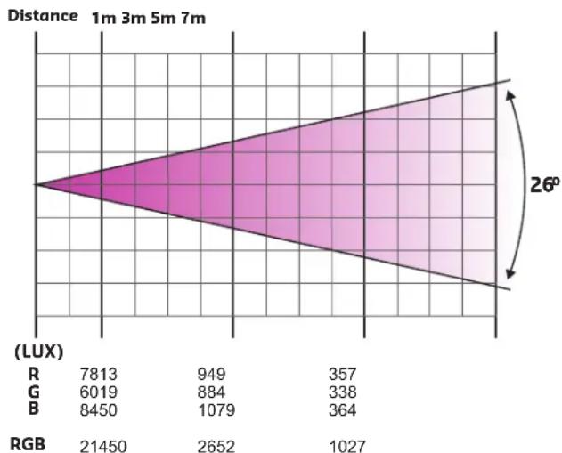
area
| | Value | | ------ | ------ | | R | 7813 | | G | 6019 | | B | 8450 | | RGB | 21450 | | | 2652 | | | 1027 | | | 364 | | | 338 | | | 884 | | | 949 | | | 357 | | | 26° |PHOTOMETRISCHES DIAGRAMM
REINIGING EN ONDERHOUD
| Mode/Channel | Value | Function | |
| CH29 | CH11 | ||
| 1 | 1 | Dimmer | |
| 0..255 | Dimmer 0%...100% | ||
| 2 | 2 | Shutter | |
| 0..31 | Shutter closed | ||
| 32..63 | shutter open | ||
| 64..95 | Strobe effect slow to fast | ||
| 96..127 | shutter open | ||
| 128..159 | Pulse-effect in sequences slow to fast | ||
| 160..191 | shutter open | ||
| 192..223 | Random strobe effect slow to fast | ||
| 224..255 | shutter open | ||
| 3 | 3 | Red | |
| 0..255 | 0-100% Red dimmer from dark to bright | ||
| 4 | 4 | Green | |
| 0..255 | 0-100% Green dimmer from dark to bright | ||
| 5 | 5 | Blue | |
| 0..255 | 0-100% Blue dimmer from dark to bright | ||
| 6 | Red in Pixel 1 | ||
| 0..255 | Red in pixel 1 saturation control (0-100%) | ||
| 7 | Green in Pixel 1 | ||
| 0..255 | Green in pixel 1 saturation control(0-100%) | ||
| 8 | Blue in Pixel 1 | ||
| 0..255 | Blue in pixel 1 saturation control(0-100%) | ||
| 9 | Red in Pixel 2 | ||
| 0..255 | Red in pixel 2 saturation control (0-100%) | ||
| 10 | Green in Pixel 2 | ||
| 0..255 | Green in pixel 2 saturation control(0-100%) | ||
| 11 | Blue in Pixel 2 | ||
| 0..255 | Blue in pixel 2 saturation control(0-100%) | ||
| 12 | Red in Pixel 3 | ||
| 0..255 | Red in pixel 3 saturation control (0-100%) | ||
| 13 | Green in Pixel 3 | ||
| 0..255 | Green in pixel 3 saturation control(0-100%) | ||
| 14 | Blue in Pixel 3 | ||
| 0..255 | Blue in pixel 3 saturation control(0-100%) | ||
| 15 | Red in Pixel 4 | ||
| 0..255 | Red in pixel 4 saturation control (0-100%) | ||
| 16 | Green in Pixel 4 | ||
| 0..255 | Green in pixel 4 saturation control(0-100%) | ||
| 17 | Blue in Pixel 4 | ||
| 0..255 | Blue in pixel 4 saturation control(0-100%) | ||
| 18 | Red in Pixel 5 | ||
| 0..255 | Red in pixel 5 saturation control (0-100%) | ||
| 19 | Green in Pixel 5 | ||
| 0..255 | Green in pixel 5 saturation control(0-100%) | ||
| 20 | Blue in Pixel 5 | ||
| 0..255 | Blue in pixel 5 saturation control(0-100%) | ||
| 21 | Red in Pixel 6 | ||
| 0..255 | Red in pixel 6 saturation control (0-100%) | ||
| 22 | Green in Pixel 6 | ||
| 0..255 | Green in pixel 6 saturation control(0-100%) | ||
| 23 | Blue in Pixel 6 | ||
| 0..255 | Blue in pixel 6 saturation control(0-100%) | ||
| 24 | 6 | Macro Color | |
| 0..23 | No Function | ||
| 24..47 | Red | ||
| 48..71 | Green | ||
| 72..95 | Blue | ||
| 96..119 | Red+Green | ||
| 120..143 | Red+Blue | ||
| 144..167 | Green+Blue | ||
| 168..191 | GRB | ||
| 192..198 | 2700K | ||
| 199..205 | 3200K | ||
| 206..212 | 3500K | ||
| 213..219 | 5000K | ||
| 220..226 | 5500K | ||
| 227..233 | 6000K | ||
| 234..240 | 6500K | ||
| 241..247 | 7000K | ||
| 248..255 | 8000K | ||
| 25 | 7 | Color Temp | |
| 0..15 | No Function | ||
| 16..45 | Below 3200K | ||
| 46..75 | 3200K - 3500K | ||
| 76..105 | 3500K - 5000K | ||
| 106..135 | 5000K - 5500K | ||
| 136..165 | 5500K - 6000K | ||
| 166..195 | 6000K - 6500K | ||
| 196..225 | 6500K - 7000K | ||
| 226..255 | 7000K - 8000K | ||
| 26 | 8 | Macro RUN | |
| 0..15 | No function | ||
| 16..31 | Macro Run 1 | ||
| 32..47 | Macro Run 2 | ||
| 48..63 | Macro Run 3 | ||
| 64..79 | Macro Run 4 | ||
| 80..95 | Macro Run 5 | ||
| 96..111 | Macro Run 6 | ||
| 112..127 | Macro Run 7 | ||
| 128..143 | Macro Run 8 | ||
| 144..159 | Macro Sound 1 | ||
| 160..175 | Macro Sound 2 | ||
| 176..191 | Macro Sound 3 | ||
| 192..207 | Macro Sound 4 | ||
| 208..223 | Macro Sound 5 | ||
| 224..239 | Macro Sound 6 | ||
| 240..255 | Macro Sound 7 | ||
| 27 | 9 | Macro Speed | |
| 0..255 | Macro Speed from Slow To Fast | ||
| 28 | 10 | Dynamic Rotate | |
| 0..15 | No function | ||
| 16..31 | Dynamic Rotate 1 | ||
| 32..47 | Dynamic Rotate 2 | ||
| 48..63 | Dynamic Rotate 3 | ||
| 64..79 | Dynamic Rotate 4 | ||
| 80..95 | Dynamic Rotate 5 | ||
| 96..111 | Dynamic Rotate 6 | ||
| 112..127 | Dynamic Rotate 7 | ||
| 128..143 | Dynamic Rotate 8 | ||
| 144..159 | Dynamic Rotate 1 | ||
| 160..175 | Dynamic Rotate 2 | ||
| 176..191 | Dynamic Rotate 3 | ||
| 192..207 | Dynamic Rotate 4 | ||
| 208..223 | Dynamic Rotate 5 | ||
| 224..239 | Dynamic Rotate 6 | ||
| 240..255 | Dynamic Rotate 7 | ||
| 29 | 11 | Dynamic Rotate Speed | |
| 0..255 | from Slow To Fast | ||
natural_image
Close-up of a black rectangular object with a dashed white line, no visible text or symbolsAFX LIGHT
- EXPLANATION OF SYMBOLS
- CAUTION DO NOT OPEN THE HOUSING SHOCK HAZARD
- SAFETY RECOMMENDATIONS
- DISCONNECT DEVICE
- INSTALLATION
- POWER SUPPLY AND SIGNAL CABLE CONNECTION
- Mains Power connection
- Connection of Signal Cable
- CONTROL PANEL
- IR REMOTE CONTROLLER
- INSTALLING THE BATTERIES IN THE REMOTE CONTROL
- RECOMMENDATIONS FOR BATTERIES
- REMOTE CONTROL
- NOTE: PLEASE SET THE UNIT TO MODE -> ADDR, OTHERWISE THE REMOTE CONTROL WILL NOT WORK
- CLEANING AND USING FREQUENCY OF PRODUCT
- MANUEL D'UTILISATION
- DESCRIPTION
- DISPOSITIF DE COUPURE
- PHOTOMETRISCHES DIAGRAMM
- REINIGING EN ONDERHOUD
- AFX LIGHT
Brand : AFX
Model : CLUB-MATRIX
Category : Lighting