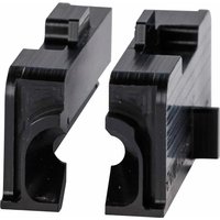
BSP45 - Label printer BRADY - Free user manual and instructions
Find the device manual for free BSP45 BRADY in PDF.


| Product Type | Sleeve applicator for wire/cable (label printer) |
| Brand | Brady |
| Model | BSP45 |
| Weight | 19 kg (42 lb) |
| Power supply | 100-240 V, 50/60 Hz, 2 A |
| Required air pressure | 2.8 to 10 bar (max. 1.0 MPa) |
| Pneumatic connector | NPTF 1/4 in, 18 threads per inch |
| Operating temperature | 5 to 40 °C |
| Relative humidity | 10 to 80% |
| Maximum altitude | 2,000 m |
| Fuse | 5 x 20 mm, 2 A, 250 V, slow-blow |
| Foot switch | 30 V max., 3 A, class 2 |
| Supported materials | Brady sleeves specific for BSP45 |
| Main functions | Automatic sleeve application, foot-pedal-high procedure, die and mandrel change |
| Maintenance | Cleaning with denatured alcohol or wipes, cleaning dies, replacing fuse |
| Safety | Emergency stop button, safety lock, emergency stop |
| Available spare parts | Dies, mandrels, fuse, pedal |
| Included accessories | Power cord, pedal, dies, mandrel assembly, manual on memory card |
| Intended use | Bench machine for applying sleeves to wires and cables |
Frequently Asked Questions - BSP45 BRADY
User questions about BSP45 BRADY
0 question about this device. Answer the ones you know or ask your own.
Ask a new question about this device
Download the instructions for your Label printer in PDF format for free! Find your manual BSP45 - BRADY and take your electronic device back in hand. On this page are published all the documents necessary for the use of your device. BSP45 by BRADY.
USER MANUAL BSP45 BRADY
natural_image
Exterior view of a Bruady-brady industrial machine (no signage or text in focus)English
Deutsche
Français
Nederlands
Español
Svenska
BSP45 Wire/Cable
Sleeve Applicator
User's Manual
Copyright
This manual is copyrighted with all rights reserved. No portion of this manual may be copied or reproduced by any means without the prior written consent of BRADY Worldwide, Inc.
While every precaution has been taken in the preparation of this document, BRADY assumes no liability to any party for any loss or damage caused by errors or omissions or by statements resulting from negligence, accident, or any other cause. BRADY further assumes no liability arising out of the application or use of any product or system described, herein; nor any liability for incidental or consequential damages arising from the use of this document. BRADY disclaims all warranties or merchantability of fitness for a particular purpose.
Trademarks
BSP45 Sleeve Applicator is a trademark of BRADY Worldwide, Inc.
BRADY reserves the right to make changes without further notice to any product or system described herein to improve reliability, function, or design.
© 2016 BRADY Worldwide, Inc. All Rights Reserved
Printed April 2016
Software Version 1
Brady Worldwide Inc.
6555 West Good Hope Road
Milwaukee, WI 53223 U.S.A.
Telephone: 414-358-6600 USA Domestic
Facsimile: 414-438-6958
UNITED STATES
FCC Notice - US Only
This equipment has been tested and found to comply with the limits for a Class A digital device, pursuant to part 15 of the FCC Rules. These limits are designed to provide reasonable protection against harmful interference when the equipment is operated in a commercial environment. This equipment generates, uses, and can radiate radio frequency energy and, if not installed and used in accordance with the instruction manual, may cause harmful interference to radio communications. Operation of this equipment in a residential area is likely to cause harmful interference in which case the user will be required to correct the interference at his own expense.
Changes or modifications not expressly approved by the party responsible for compliance could void the user's authority to operate the equipment.
INDUSTRY CANADA
Industry Canada ICES-03:
CAN ICES-03(A) NMB-03(A)
EUROPE
Warning - This is a Class A product. In a domestic environment, this product may cause radio interference in which case the user may be required to take adequate measures.
Waste Electrical and Electronic Equipment Directive
In accordance with the European WEEE Directive, this device needs to be recycled in accordance with local regulations.
RoHS Directive 2011/65/EU
This product is CE marked and complies with the European Union's Directive 2011/65/EU OF THE EUROPEAN PARLIAMENT AND OF THE COUNCIL of 8 June 2011 on the restriction of the use of certain hazardous substances in electrical and electronic equipment.
Our products are sold with the understanding that the buyer will test them in actual use and determine for him or herself their adaptability to his/her intended uses. BRADY warrants to the buyer that its products are free from defects in material and workmanship, but limits its obligation under this warranty to replacement of the product shown to BRADY's satisfaction to have been defective at the time BRADY sold it. This warranty does not extend to any persons obtaining the product from the buyer.
THIS WARRANTY IS IN LIEU OF ANY OTHER WARRANTY, EXPRESSED OR IMPLIED INCLUDING, BUT NOT LIMITED TO ANY IMPLIED WARRANTY OF MERCHANTABILITY OR FITNESS FOR A PARTICULAR PURPOSE, AND OF ANY OTHER OBLIGATIONS OR LIABILITY ON BRADY'S PART. UNDER NO CIRCUMSTANCES WILL BRADY BE LIABLE FOR ANY LOSS, DAMAGE, EXPENSE OR CONSEQUENTIAL DAMAGES OF ANY KIND ARISING IN CONNECTION WITH THE USE, OR INABILITY TO USE, BRADY'S PRODUCTS.
YOU SHOULD CAREFULLY READ THE FOLLOWING TERMS & CONDITIONS OF THIS LICENSE AGREEMENT. IF YOU DO NOT AGREE WITH THESE TERMS & CONDITIONS, PLEASE PROMPTLY RETURN THIS PACKAGE FOR A FULL REFUND.
Please read these instructions completely and carefully before operating your BSP45 Sleeve Applicator machine. Keep this Instruction Manual for future reference.
Intended Use
The BSP45 Wire/Cable Sleeve Applicator is a benchtop machine that assists in the application of sleeves to wires and cables. If the equipment is used in a manner not specified by the manufacturer, the protection provided by the equipment may be impaired.
Warnings:
 | DO NOT insert fingers or hands into die module opening; pinch hazard. |
 | DO NOT operate machine with covers open. |
 | DO NOT power up the machine when any of the shrouds are removed (tool required); electrical hazard. See Maintenance section. |
 | ALWAYS unplug power cord to disable power when servicing. |
Cautions:
- ALWAYS wear safety glasses during operation of the machine and/or servicing to prevent eye damage in the case of flying debris from a broken mandrel.
- ALWAYS use E-Stop button in the event of a emergency to disable die module, mandrel & pneumatic operation.
- ALWAYS use proper instructions for dropped sleeves. Refer to "Recovering from a Dropped Sleeve" section on page 11.
- ALWAYS use proper instructions for machine error in "Recovering from an Error" section provided.
• ALWAYS use Brady sleeves/material, when operating the machine. - NEVER insert more than one wire, or bundle, into machine.
- NEVER insert any object other than the appropriate-sized wire.
• DO NOT place the machine on an unstable surface or stand. - DO NOT position the machine such that the electric and pneumatic power cannot be readily disconnected.
• ALWAYS use handles provided at bottom front and back to lift machine.
• DO NOT place anything on machine. Keep clear of obstruction
• DO NOT wear loose clothing that could become caught in the machine. - ALWAYS use the machine in a well-ventilated area. DO NOT block the slots and opening on the machine, which are provided for ventilation.
• ALWAYS use the power source indicated on the rating label.
• ALWAYS use only the power cord provided with the machine. - ALWAYS connect the three-conductor plug to AC outlet. Be sure the outlet is grounded and easily accessible to the unit.
• ALWAYS use air pressure greater than 40 psi but less than 145 psi. - DO NOT operate machine in direct sunlight.
• ALWAYS allow machine to acclimate to ambient temperature for an hour before operating. - Make sure you have easy access to the main plug in case of an emergency. In case of an emergency, immediately unplug the unit from the wall AC outlet.
BSP45 Sleeve Applicator
• Voltage: 100 - 240 V, 50/60 Hz, 2A
- Mechanicals:
- Max input air pressure 145 PSI (1.0 MPa).
- Pneumatic connector, industrial quick coupler plug, 1/4" NPTF, 18 threads per inch.
- Filtered air supply source recommended.
-
Supplied air should NOT contain in-line oil in the compressor hose.
-
Operating Temperature: 41 to 104^ (5 - 40°C)
• Relative Humidity: 10% to 80% RH
• Weight: 42 lbs (19 kg)
• Altitude of Operation: up to 2000M
Media Specifications
The BSP45 Sleeve Applicator is designed to function only with a specific range of Brady sleeve parts constructed to allow correct feed, sensing, and auto-application by the machine. Non-Brady sleeve parts and non-BSP45-specific sleeve parts will not function in the system. Contact Brady Technical Support or Customer Support for specific media information.
BSP45 Footswitch
30V AC Max, 3A, Class 2 Circuits only, EN 60529 (IP20), UL REC / E83123
Technical Support Numbers/On-line Help
For repair or technical assistance, find your regional Brady Technical Support in the following table.
Country Website Telephone Email
| United States | www.bradyid.com 1-800-643-87 | 766 tech_support@bradycorp.com | |
| Canada www.bradycanada.ca 1-800-263-6179 | bradycanada_technicalsupport@bradycorp.com | ||
| Mexico www.bradylatinamerica.com 1-800-212 | -8181 soporte_tecnico@bradycorp.com | ||
| Central America | www.bradylatinamerica.com 1-866-748-4424 soporte_tecnico@bradycorp.com | ||
| South America | www.bradylatinamerica.com 1-866-748-4424 soporte_tecnico@bradycorp.com | ||
| Brazil www.brady.com.br +55 11 4166- | 1500 ext 5 | at@bradycorp.com | |
| Australia | http://www.bradyid.com.au | 1800 644 834 | brady_aust@bradycorp.com |
| Europe | www.bradyeurope.com | +44 333 333 1111 | tseurope@bradycorp.com |
| South Asia | http://www.bradyid.com.sg | 65-64777261 | technicalsupport_sa@bradycorp.com |
Repair and Replacement Parts
Brady Corporation offers repair and replacement services. Contact Brady Technical Support for repair and replacement information.
Unpack Your Applicator ....1
Register Your Sleeve Applicator ....1
External View.... 2
Sleeve Applicator Setup 3
Changing Dies/Sleeve Size.... 4
Changing Mandrel.... 5
Loading Media 6
Selecting a Sleeve 9
Applying a Sleeve (IN-PEDAL-UP)....10
Stopping the Application ....11
Recovering from a Dropped Sleeve ....11
Maintenance 12
Cleaning the Applicator ....12
Fuse 12
Cleaning Dies 12
Troubleshooting.... 13
Recovering from Errors ....17
Appendix A - Loading Material on BBP72 Printer ....18
Appendix B - Loading Material on PR300+ Printer ...19
Template Side #1 (first side to print for 1- and 2-sided printing) ....19
Template Side #2 (second side for double-sided printing) ......20
Unpack Your Applicator
Carefully remove any transportation protection from between the Die opening and the area in front of the Poke and Lift Module.
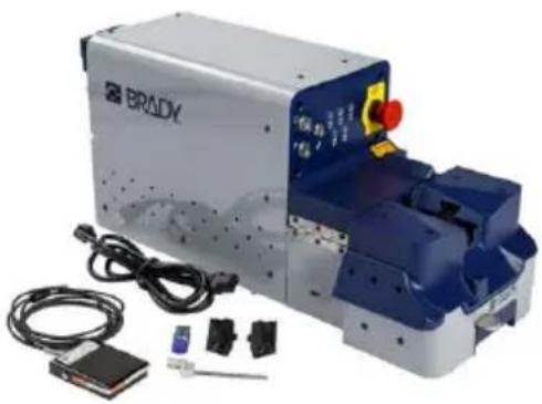
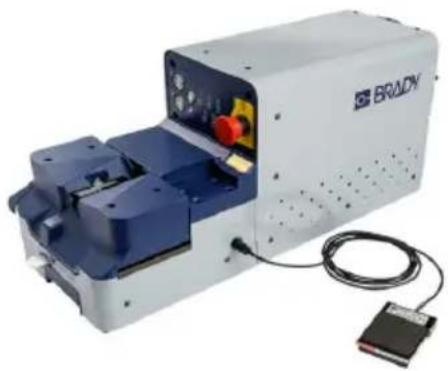
The following items are included in the standard BSP45 Sleeve Applicator package:
• BSP45 Wire/Cable Sleeve Applicator
- User's Manual (on memory stick)
- Power Cord
• Dies
- Mandrel Assembly
- Foot pedal
natural_image
Exterior view of a Bruk-branded industrial machine with control panel and wiring (no visible text or symbols)Register Your Sleeve Applicator
Register your applicator on-line at www.bradycorp.com/register and receive free product support and updates.
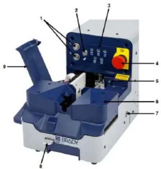
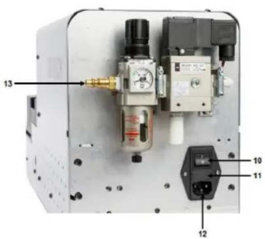
1 | Start/Stop buttons
2Function button 9Rear door
3 Sleeve size selection buttons
4E-stop button 11Fuse
5 Rear door safety lock
6D|e module 13Pneumatic hose attachment
7Foot pedal jack
8 | Die module release lever
10 On/Off switch
12 Power cord connection
Sleeve Applicator Setup
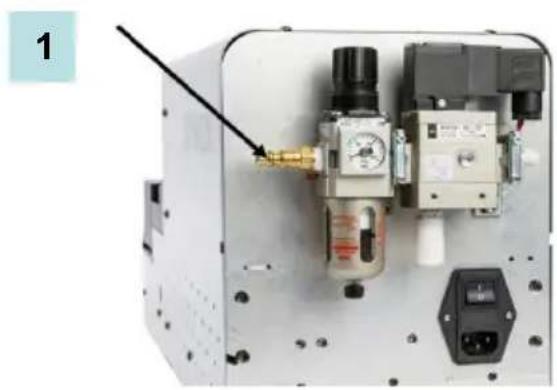
- Attach free end of the pneumatic hose that is attached to an air compressor to the male connector on the BSP45 unit. MAKE SURE THE PNEUMATIC LINE IS FREE OF OIL.
Note: Air pressure must be greater than 40 psi but less than 145 psi.
- Plug in the foot pedal.
natural_image
Close-up of a mechanical device with pressure gauges and control buttons (no visible text or symbols)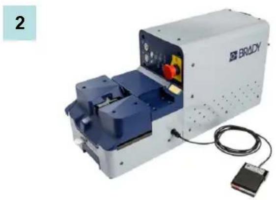
natural_image
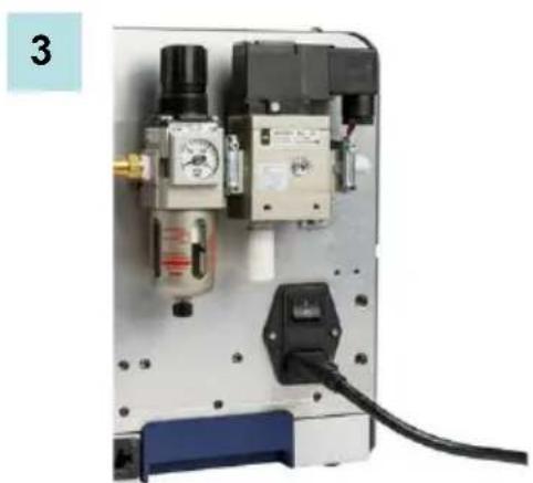
Exterior view of a Bruady industrial machine with blue components and wiring (no visible text or symbols)- Attach the power cord (included) to the applicator and plug into an electrical outlet, then flip the electrical switch on the back of the applicator to the ON (I) position.
natural_image
Close-up of a mechanical control panel with pressure gauges, tubing, and a black electrical outlet (no visible text or symbols)4 Changing Dies/Sleeve Size ENGLISH
Changing Dies/Sleeve Size
In order to apply the desired sleeve, you must install the correct mandrel and dies that correspond to the chosen sleeve diameter. For instance, for 0.125-inch diameter sleeves, the associated 0.125-inch mandrel and 0.125-inch dies must be installed. Both the mandrel and the dies are stamped with the sleeve diameter.
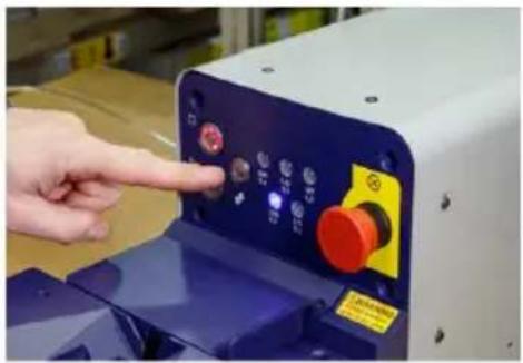
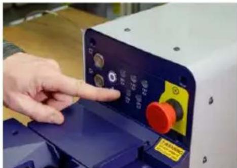
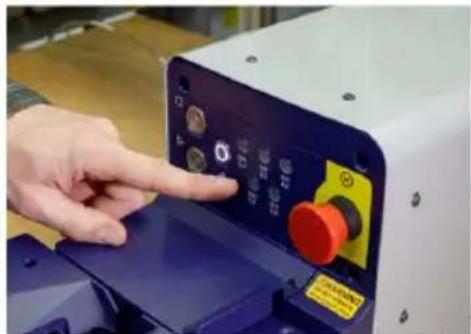
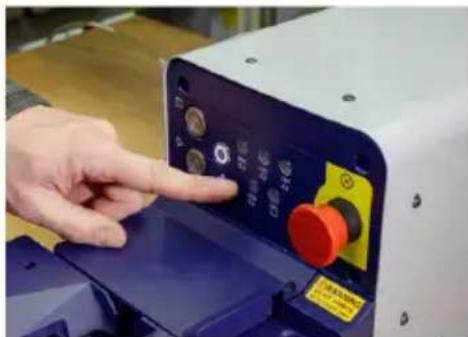
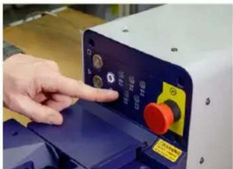
- Press the Function button on the bezel.
Both dies display.
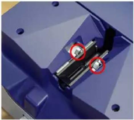
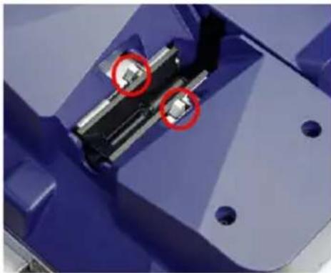
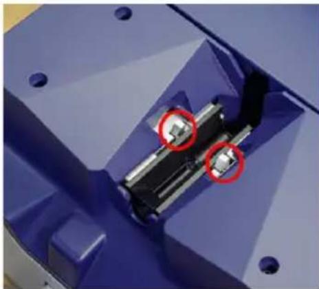
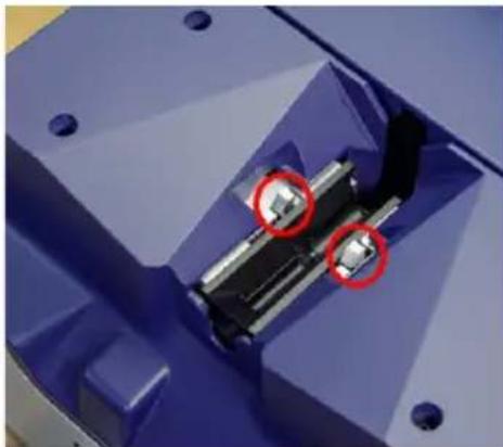
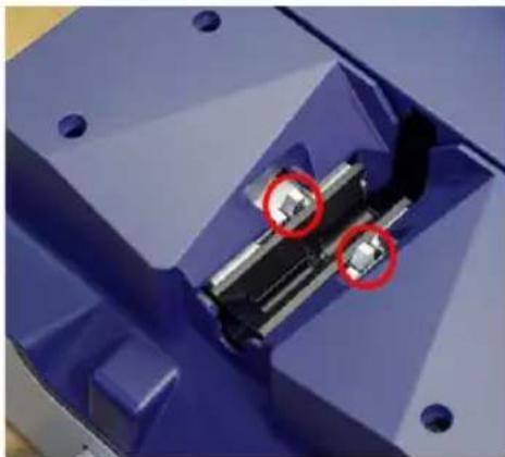
- Push the silver die release tab (circled) toward the back of the machine. While holding the release tab with one hand, with the other hand grasp the die and pull straight up and out.
1
natural_image
Close-up of a hand pointing at a control panel with red buttons and indicator lights (no visible text or symbols)2
natural_image
Close-up of a mechanical component with two red-circled features, no visible text or symbols-
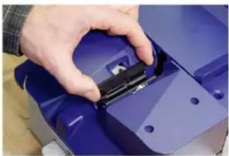
Insert the desired die into the slot and gently push down until it clicks. The release tab will flip back into place.
-
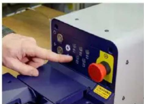
On the unit's front panel, press the sleeve size selection button corresponding to the size of the inserted dies.
3
natural_image
Close-up of a hand placing a black plastic component into a blue plastic housing (no visible text or symbols)4
natural_image
Close-up of a hand pressing a button on a machine control panel (no visible text or symbols)The dies return back under the housing. The machine is now ready for operation.
See Changing Mandrel (page 5) to complete the material changeover process.
Install the mandrel that corresponds to the chosen sleeve diameter. The sleeve diameter is stamped on the side of the mandrel block.
Note: If only changing the mandrel (not the dies), the Function button does not have to be pressed.
For this procedure, you will need a #1 drive Philips head screw driver.
-
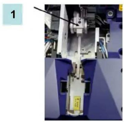
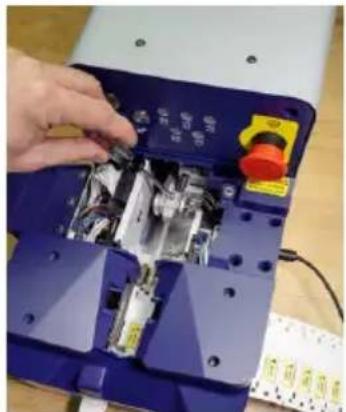
Open the access door to display the mandrel assembly.
-
Unscrew the mandrel holder with the Philips head screw driver.
natural_image
Close-up of a mechanical assembly with blue components and a yellow label (no readable text or symbols)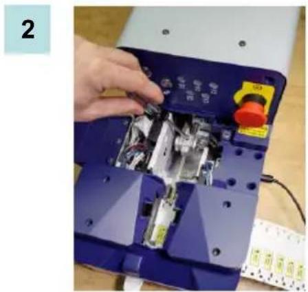
natural_image
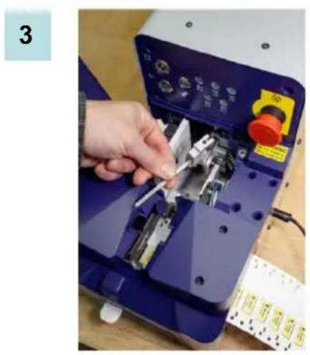
Close-up of a hand installing or adjusting electronic components on a blue electronic device (no visible text or symbols)- Pull out the installed mandrel assembly. 4. Insert another mandrel assembly (corresponding to the size previously selected on the bezel and as indicated by the dies) and secure by tightening the screws.
natural_image
Close-up of a hand using a blue industrial machine to adjust metal components (no visible text or symbols)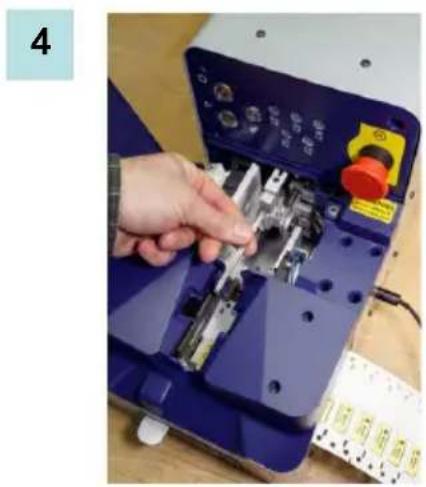
natural_image
Hand operating a blue industrial machine with a hand adjusting the internal components (no visible text or symbols)-
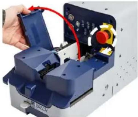
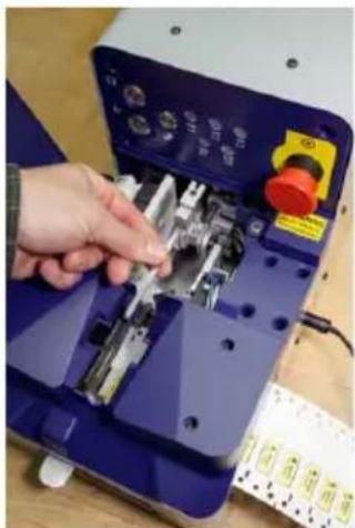
Ensure that the E-stop (safety switch) is released. If not, twist the red E-stop knob clockwise and pull out. Then, gently lift the rear door. Opening this door releases the safety lock, which automatically evacuates the system air and removes electrical power.
-
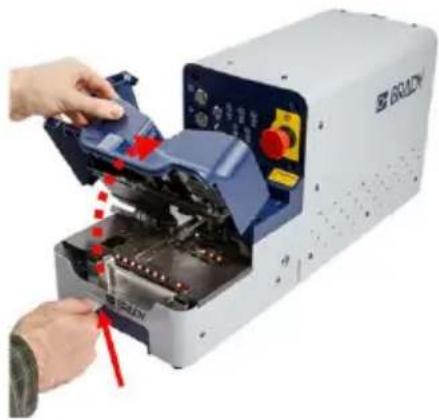
Press the extended latch on the lower front of the die module to release it. The die module automatically opens to a set position.
1
natural_image
Close-up of a hand inserting a blue plastic component into a white industrial machine, with red cable and control buttons visible (no text or symbols)2
natural_image
Close-up of a white Balcon industrial machine with a hand inserting a component, showing no visible text or symbols.-
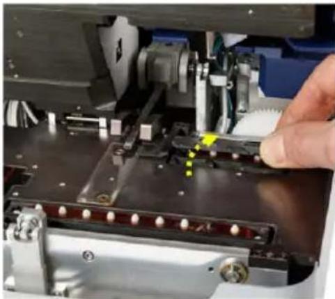
Lift and flip up the door covering the rear tractor pin feed.
-
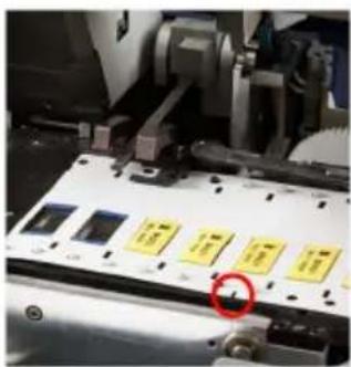
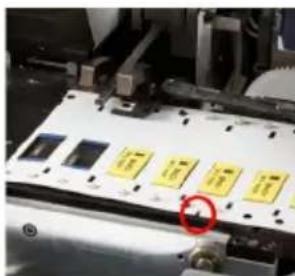
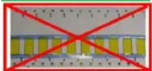
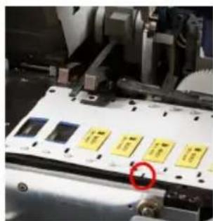
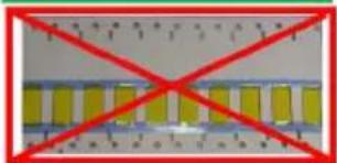
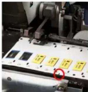
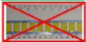
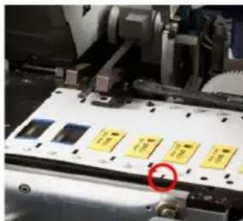
Load the media with the notch on the edge of the cardstock (marked with the red circle) facing towards the front of the unit. The blue lines on the back of the cardstock should face down. A minimum cardstock length of 6 inches is required
Note: For proper operation, the minimum length of media that can be loaded is 6 inches.
3
natural_image
Close-up of a mechanical assembly with a hand pressing a component (no visible text or symbols)4
natural_image
Close-up of a mechanical device with yellow and black components, no visible text or symbols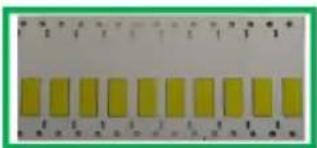
natural_image
Close-up of a yellow rectangular object with measurement markings (no visible text or symbols)Correct
natural_image
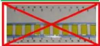
Pure electrical circuit lines without any symbolsIncorrect
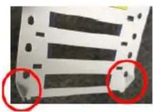
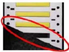
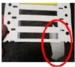
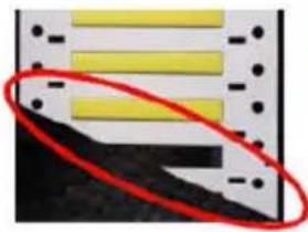
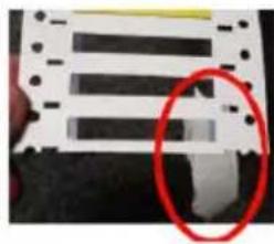
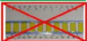
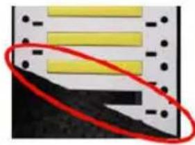
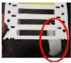
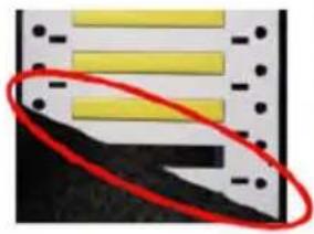
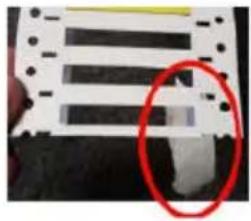
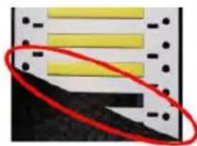
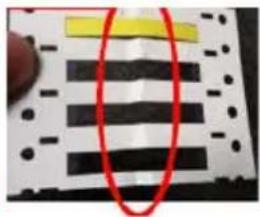
The edge of the cardstock should be flat and in "out of the box" condition. Below are examples of damaged material, which should be trimmed to remove the damaged portion of the media.
natural_image
Close-up of a striped fabric with two red-circled regions highlighting specific areas (no text or symbols visible)Curled edges
natural_image
Close-up of a yellow panel with black base and red oval highlight (no text or symbols)Extreme angle cut
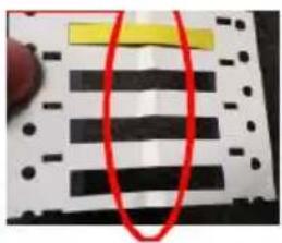
Damaged ladder
natural_image
Close-up of a striped electronic component with a red-circled detail (no visible text or symbols)Tape on end of cardstock
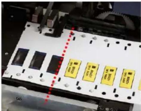
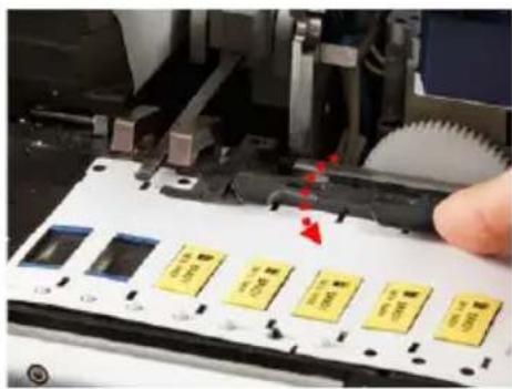
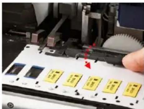
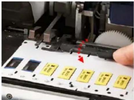
- Feed the card-stock into the unit, engaging all tractor pins. If there are sleeves missing, when started, the machine automatically advances to the first available sleeve.
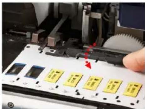
To avoid wasting sleeves, ensure that the mandrel is inserted into the first viable sleeve. Unused stock rolls have several blank sleeve windows (as shown in Figure 5 below). The red dotted line in Figure 5 indicates where the cardstock should be inserted and engaged.
- Close the door on the rear tractor feed.
Note: If the tractor door is not closed before closing the die module, it could stall the motor.
5
6
natural_image
Close-up of a hand pressing down on a mechanical component with yellow and blue buttons, no visible text or symbols8 Loading Media ENGLISH
-
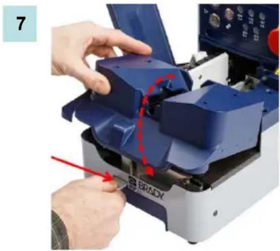
Press and hold the extended latch on the die module while pushing the die module down. When the module is closed, release the latch.
-
Close the rear door. The safety lock engages again when the door is shut. The STOP button is lit, signifying the machine is ready.
natural_image
Close-up of hands operating a blue industrial machine with a red arrow pointing to a component labeled 'BRADY' (no text or symbols on the machine itself)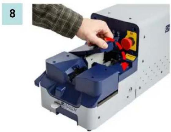
natural_image
Person operating a device with red buttons and blue components, no visible text or symbols
WARNINGWARNINGWARNING
DO NOT insert fingers or hands into die module opening - pinch hazard!
DO NOT operate machine with covers open!
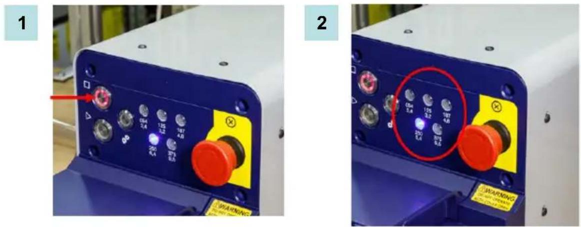
A new sleeve size must be selected whenever the media is changed.
-
Press the Stop button.
-
Press the sleeve selector button.
Refer to Changing Dies/Sleeve Size (page 4) and Changing Mandrel (page 5) to complete the media changeover.
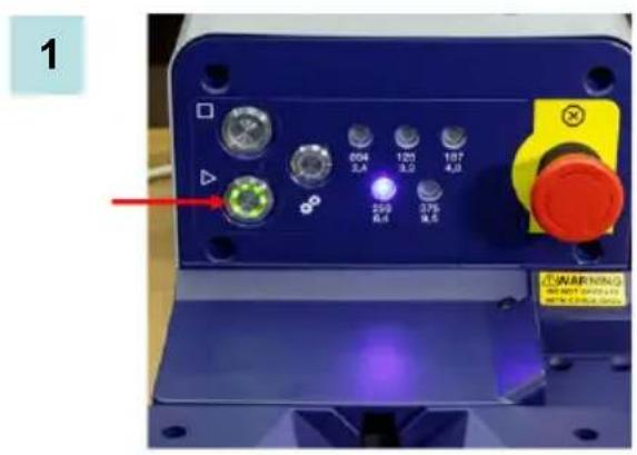
- After the dies and mandrel are changed, press the Start button to continue applying sleeves.

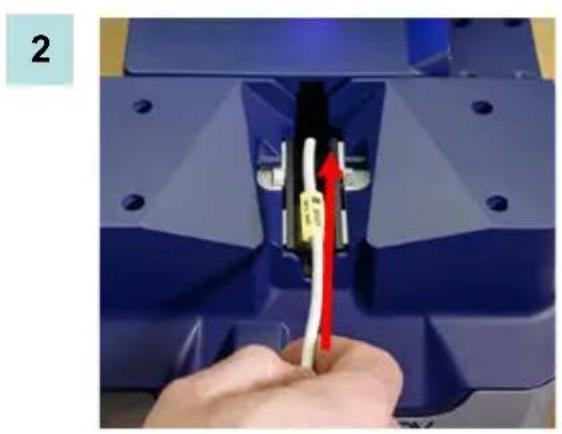
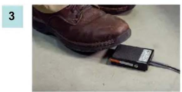
Applying a sleeve is as simple as 1-2-3. It involves a 3-step procedure called IN-PEDAL-UP. IN-PEDAL-UP is done rapidly but after a few tries you will develop a rhythm to it and the procedure will be seamless
-
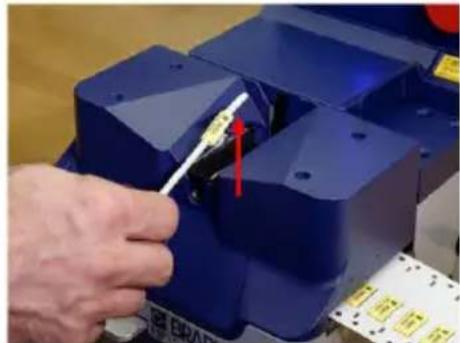
Press the START button to advance the media to the first sleeve. The unit compresses the sleeve from both sides, creating the opening through which the wire is passed.
-
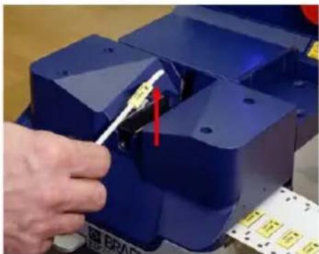
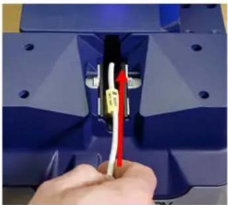
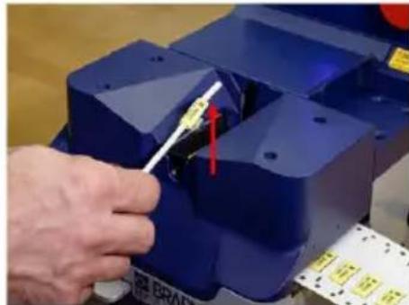
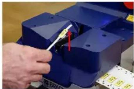
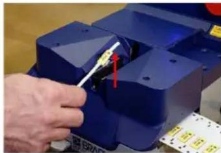
Insert a wire into the open sleeve, making sure the wire passes completely through the open sleeve. (IN)
natural_image
Close-up of a hand inserting a cable into a blue industrial component with a white connector (no text or symbols visible)- Tap the foot pedal with your foot. (PEDAL) 4. Quickly lift the wire up and out of the die module. (UP)

DO NOT insert fingers or hands into die module opening; pinch hazard. DO NOT operate machine with covers open.
natural_image
Close-up of a brown leather shoe next to a small black electronic device with a cable, placed on a plain surface (no visible text or symbols)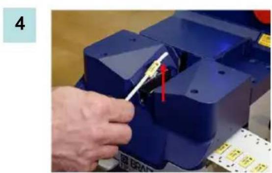
natural_image
Close-up of a hand using a tool to adjust or install a blue mechanical component, with no visible text or symbols.When you have reached the last sleeve you want to apply to a wire:
- Insert the wire into the sleeve.
- Press STOP button (NOT the foot pedal).
Pressing the STOP button releases the last sleeve, so there is no waste.
Note: On the last sleeve, if the stop button is pressed BEFORE inserting a wire into the sleeve, the last sleeve will fall into the machine, possibly causing a jam

WARNINGWARNINGWARNING
If the machine does not stop, press the E-Stop button to cut all power to the system. DO NOT stick hands or fingers into the machine until all power has been stopped.
Recovering from a Dropped Sleeve
If a sleeve drops down inside the machine, use the following procedure to retrieve the sleeve.
- Press the STOP button, if it is not red. If it is red, the machine has already stopped.
- Open the rear door.
- Open the die module.
- Remove the loose sleeve from inside the machine.
- Close the die module.
- Close the rear door.
The buttons are now active and the STOP button is red. Press the START button and follow the IN-PEDAL-UP procedure to continue the job.

WARNINGWARNINGWARNING
DO NOT power up machine when any of the shrouds are removed (a tool is required)
- Electrical hazard!
ALWAYS unplug power cord to disable power when servicing!
Cleaning the Applicator
To clean the applicator:
- Remove media.
- Dampen a non-abrasive cloth with denatured alcohol or use a pre-moistened eye glass lens cleaning towelette.
- Gently wipe the cloth across the media plate and lenses.
- Repeat as often as required to maintain applicator functionality.
Fuse
The specifics for the fuse on the rear of the panel, below the on/off switch are as follows:
Size: 5 x 20 mm
Current: 2A
Voltage: 250 VAC
Type: Time lag
Cleaning Dies
To clean the dies:
- Remove the dies. (See Changing Dies on page 4 of this document.)
- Dampen a non-abrasive cloth with denatured alcohol or use a pre-moistened eye glass lens cleaning towelette.
- Gently wipe the dirty portion of the die with the alcohol-dampened cloth until debris is removed.
- Repeat as often as necessary to maintain die functionality.
Troubleshooting
When an error occurs, the code displays in the form of a blinking red and/or green light on the main bezel of the machine. The different errors can be interpreted by watching the sequences of the blinking lights. These blinking light codes are outlined in the "Issue/Error Code" column of this troubleshooting guide.
| Issue/Error Code Problem Solution | ||
| Alternating Red and Green Lights (Error code 1) | ||
| Media jam | Open the rear door and the die module.Clear the jam.Close the rear door and die module | |
| Sensor failure | Open access door to reset error.Close cover.If problem persists, contact Brady Technical Support | |
| 2 Red blinks, pause, repeat (Error code 2) | ||
| PLM location sensors not working | Open access door to reset error.Close cover.If problem persists, contact Brady technical support | |
| Solenoid valves not firing | Open access door to reset error.Close cover.If problem persists, contact Brady technical support | |
| 3 Red blinks, pause, repeat (Error code 3) | ||
| One or both of the dies are stuck open or closed | Ensure dies are free of debris.Reinstall both dies and ensure proper fit.If problem persists contact Brady technical support | |
| Die location sensors not working | Call Brady Technical Support for assistance | |
| 4 Red blinks, pause, repeat (Error code 4) | ||
| Non Brady material or material not sensing material properly | Make sure that the material is Brady BSP45 material.After a period of 2 minutes the Stop button will be solid red.Open and close the cover doorORPress and depress the E-Stop to resume normal operation.The machine will lock for 2 minutes then return to normal operation.Note: Do NOT turn off the machine as it will reset the 2 minute timer. | |
| Debris covering BP window | Make sure that debris is not covering the BP window.After a period of 2 minutes the Stop button will be solid red.Open and close the cover doorORPress and depress the E-Stop to resume normal operation.The machine will lock for 2 minutes then return to normal operation.Note: Do NOT turn off the machine as it will reset the 2 minute timer. | |
| 4 Red blinks, pause, repeat (Error code 4) (continued) | ||
| Material is installed upside down | Make sure the material is installed with the blue line facing down. See “Loading Media” on page 6 for proper installation.Open and close the access door to reset error.After a period of 2 minutes the Stop button will be solid red.Open and close the cover doorORPress and depress the E-Stop to resume normal operation.The machine will lock for 2 minutes then return to normal operation.Note: Do NOT turn off the machine as it will reset the 2 minute timer. | |
| Fast flashing STOP light Temperature | Ature change Allow one hour for machine to acclimate to ambient temperature. | |
| Excess light Remove bright lights | that are shining on or in the machine. | |
| 5 Red blinks, pause, repeat (Error code 5) | ||
| BP sensor not working Contact Brady technical support | ||
| Issue/Error Code | Problem | Solution |
| Miscellaneous Issues | ||
| Machine does not power up Switch | not activated Ensure E-Stop is not activated. | Ensure doors are closed and the rear power switch is on. |
| Blown fuse Ensure fuse in rear power switch is not blown. If it is, replace with new fuse. | ||
| Machine stopped Mandrel not correctly installed Open doors and ensure mandrel screw is tight. If not, use a #1 Phillips screw driver to tighten the screw. | ||
| Dies not installed correctly See the "Changing Dies/Sleeve Size" section (page 4) to verify the dies are properly installed. | ||
| Foot pedal not plugged in Ensure foot switch is plugged in. | ||
| Machine not opening sleeves Dies not installed correctly See "Changing Dies/Sleeve Size" section (page 4) to verify the dies are properly installed. | ||
| Machine does not open every sleeve | Sensor windows are dirty See "Cleaning the Applicator" section on page 12 of this manual. | |
| Cannot close front cover This operation requires the use of both hands | ·Ensure that the tractor feed door is closed.·Then, with one hand, push and hold the front door release lever while closing the cover door with the other hand.·Release the lever when the front door is closed. | |
| Slow operation | Low air pressure | Ensure that the air pressure is 40psi to optimize performance of machine. |
Recovering from Errors
If the machine enters an error state (caused by a missed sleeve or jammed material), the STOP button flashes red to indicate an error. Once the machine registers an error, the START and STOP buttons are no longer active until the following procedure is followed.
- Open the rear door.
- Open the die module.
- Address the error.
When the problem has been fixed:
- Close the die module.
- Close the rear door.
The buttons are now active and the STOP button is red. Press the START button and follow the IN-PEDAL-UP procedure to continue the job.
18 Appendix A - Loading Material on BBP72 Printer ENGLISH
Appendix A - Loading Material on BBP72 Printer
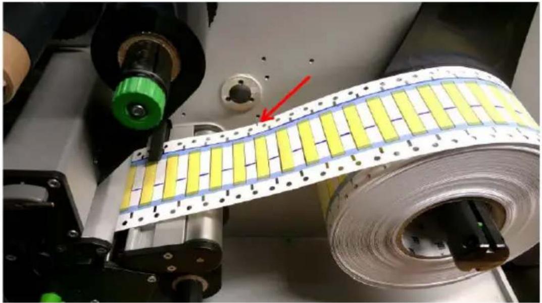
- To load the 1" & 2" sleeves and cardstock into the BBP72, orient the notch on the edge of the carstock (marked with the red arrow) towards the interior wall of the unit. The blue lines on the cardstock should face up coming off of the roll.
- Print the data onto the sleeves, starting with the data for Sleeve #1.

natural_image
Close-up of a yellow strip being processed by a mechanical assembly, with a red arrow pointing to a component (no visible text or symbols)- After printing, rewind the roll. The last sleeve printed will be the first onto the rewinder. This places the sleeve material in the correct orientation to run on the BSP45. Printed Sleeve #1 will be on the outside of the rewound roll and the first sleeve into the BSP45.
Template Side #1 (first side to print for 1- and 2-sided printing)
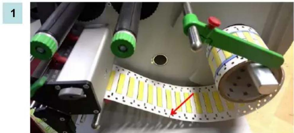
- To load the 1" & 2" sleeves and cardstock into the PR300+, orient the notch on the edge of the cardstock (marked with the red arrow) away from the interior wall of the unit. The blue lines on the cardstock should face DOWN coming off of the roll.
natural_image
Close-up of a mechanical assembly with yellow strips and green tool, no visible text or symbols- For 1-sided print, print the data onto the sleeves, starting with the data for Sleeve #1. Then, after printing, rewind the roll with the last sleeve printed being the first onto the rewinder. This places the sleeve material in the correct orientation to run on the BSP45.
OR
For 2-sided print, print the data onto the sleeves, starting with the data for the LAST sleeve. Then, rewind the roll directly out of the printer so that the data on Sleeve #1 is now on the outside of the roll.
Template Side #2 (second side for double-sided printing)
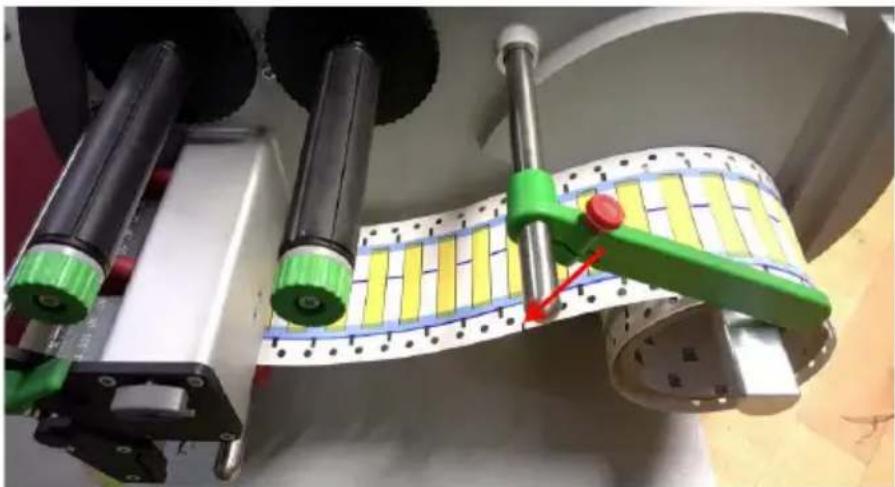
- To load the 1" & 2" sleeves and cardstock into the PR300+ to print the second (bottom side), orient the notch on the edge of the cardstock (marked with the red arrow) away from the interior wall of the unit. The blue lines on the cardstock should face UP coming off of the roll.
3
natural_image
Close-up of a mechanical assembly with green and red components, no visible text or symbols-
Print the data onto the sleeves, starting with the data for Sleeve #1.
-
Rewind the roll directly out of the printer so that Sleeve #1 data is at the core. The material is now in the correct orientation to run on the BSP45, with the last data printing being applied first. (Example: Printing serialized sleeves 1 through 100, Sleeve #100 will be applied first on the BSP45)
Copyright
Brady Worldwide Inc.
6555 West Good Hope Road
Milwaukee, WI 53223, USA
Telefon: 414-358-6600 USA Inland
Fax: 414-438-6958
USA
natural_image
Exterior view of a Bruady industrial machine with blue and gray components, no visible text or symbols on the main body.Etikettenhüllen-Applikator registrieren
natural_image
Close-up of a mechanical device with pressure gauges and control buttons (no visible text or symbols)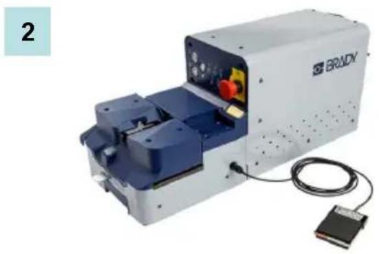
natural_image
Exterior view of a Bruady optical instrument with blue components and wiring (no visible text or symbols)natural_image
Close-up of a mechanical control panel with pressure gauges, tubing, and a black electrical outlet (no visible text or symbols)natural_image
Close-up of a hand pointing at a control panel with buttons and indicator lights (no visible text or symbols)2
natural_image
Close-up of a blue mechanical component with two red-circled features, no visible text or symbolsnatural_image
Close-up of a hand inserting a plastic component into a blue plastic housing (no visible text or symbols)4
natural_image
Close-up of a hand pointing at a control panel with buttons and a red indicator (no visible text or symbols)natural_image
Close-up of a mechanical assembly with blue components and a yellow label (no readable text or symbols)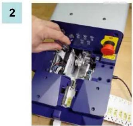
natural_image
Close-up of a hand installing or adjusting an electronic device with visible internal components and a red control knob (no text or symbols)natural_image
Hand operating a blue industrial machine with a hand adjusting metal components (no visible text or symbols)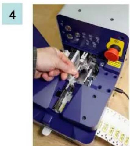
natural_image
Hand operating a blue industrial sewing machine with mechanical components and a red control knob (no visible text or symbols)natural_image
Close-up of a hand inserting a blue plastic component into a white industrial machine with red wiring (no visible text or symbols)natural_image
Close-up of a white PROCY industrial machine with a hand inserting a component, showing internal components and red arrows indicating parts (no text or symbols visible)natural_image
Close-up of a mechanical assembly with a hand pressing a component (no visible text or symbols)4
natural_image
Close-up of a mechanical device with yellow components and a red circle highlighting a specific area (no visible text or symbols)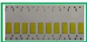
natural_image
Row of yellow rectangular blocks on a white background, no text or symbols visibleRichtig
natural_image
Pure electrical circuit lines without any symbolsFalsch
natural_image
Close-up of a mechanical device with multiple labeled components and a red dotted line indicating a measurement or alignment (no readable text or symbols)6
natural_image
Close-up of a hand inserting wires into a blue industrial machine component, with a red arrow indicating the cable direction (no text or symbols visible)natural_image
Close-up of a brown leather shoe and a small black electronic device with a cable, placed on a surface (no visible text or symbols)4
natural_image
Close-up of a hand using a tool to adjust or install a blue mechanical component, with no visible text or symbols.natural_image
Close-up of a yellow strip being cut off into a white film, with a red arrow pointing to the cutting edge (no text or symbols visible)natural_image
Close-up of a mechanical assembly with yellow strips and green handle, no visible text or symbolsnatural_image
Close-up of a mechanical assembly with green and yellow components, no visible text or symbolsBrady Worldwide Inc.
6555 West Good Hope Road
Milwaukee, WI 53223 É.-U.
BSP45 Sleeve Applicator
natural_image
Exterior view of a modern industrial machine with blue and silver components, connected to cables and sensors (no visible text or symbols)natural_image
Close-up of a mechanical pressure regulator device with attached gauges and control buttons (no visible text or symbols)2
natural_image
Exterior view of a modern scientific instrument labeled 'BRADY' with internal components and external wiring (no readable text beyond branding)natural_image
Close-up of a mechanical control panel with pressure gauges, tubing, and a black electrical outlet (no visible text or symbols)natural_image
Close-up of a hand pointing at a control panel with buttons and indicator lights (no readable text or symbols)2

natural_image
Close-up of a mechanical component with two red-circled features, no visible text or symbolsnatural_image
Close-up of a hand placing a black plastic component into a blue battery casing (no visible text or symbols)4
natural_image
Hand pointing at a control panel with buttons and a red push button (no visible text or symbols)natural_image
Close-up of a mechanical assembly with blue components and a yellow label (no readable text or symbols)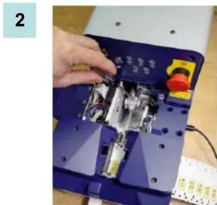
natural_image
Close-up of a hand installing or adjusting electronic components on a blue industrial machine (no visible text or symbols)natural_image
Hand operating a blue industrial machine with tools and control panel (no visible text or symbols)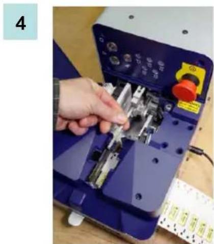
natural_image
Close-up of a hand operating a blue industrial machine with metal components and control buttons (no visible text or symbols)natural_image
Close-up of a hand holding a blue mechanical device with red cable, showing internal components and no visible text or symbols.natural_image
Close-up of a robotic device with a hand operating the top panel, showing internal components and red arrows indicating motion (no text or symbols visible)natural_image
Close-up of a hand pressing a mechanical component with a yellow arrow indicating a specific part (no visible text or symbols)4
natural_image
Close-up of a mechanical device with yellow labels and a red circle highlighting a specific component (no readable text or symbols)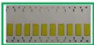
natural_image
Row of yellow rectangular blocks on a white background, no text or symbols visibleCorrect
natural_image
Pure diagram of a grid layout with red X-shaped lines and yellow cells, no text or symbols present.Incorrect
natural_image
Close-up of a striped fabric with two red-circled regions highlighting specific areas (no text or symbols visible)Rebords courbés
natural_image
Close-up of a yellow panel with black bands and a red oval highlight (no text or symbols)Échelle endommagée
natural_image
Close-up of a striped electronic component with a red oval highlighting a small feature (no text or symbols visible)natural_image
Close-up of a mechanical assembly with labeled components and a red dotted line indicating a measurement or alignment (no readable text or symbols)6

natural_image
Close-up of a hand inserting a cable into a blue electrical socket (no text or symbols visible)natural_image
Close-up of a brown leather shoe and a small black electronic device with a cable, placed on a surface (no visible text or symbols)4
natural_image
Close-up of a hand using a tool to adjust or install a blue mechanical component (no visible text or symbols)natural_image
Close-up of a yellow and white striped film strip being processed by industrial machinery, with no visible text or symbols.natural_image
Close-up of a mechanical assembly with yellow strips and green handle, no visible text or symbolsnatural_image
Close-up of a mechanical assembly with green and yellow components, no visible text or symbolsBrady Worldwide Inc.
6555 West Good Hope Road
Milwaukee, WI 53223 V.S.
BSP45 sleeve applicator
natural_image
Exterior view of a modern office building (no signage)Uw sleeve applicator registreren
Registreer uw applicator online via www.bradycorp.com/register en ontvang gratis productondersteuning en updates!
©
Instellen sleeve applicator
natural_image
Close-up of a mechanical control panel with pressure gauges, tubing, and a black electrical outlet (no visible text or symbols)natural_image
Close-up of a hand pressing a button on a blue industrial machine (no visible text or symbols)2
natural_image
Close-up of a mechanical component with two red-circled features, no visible text or symbolsnatural_image
Close-up of a hand inserting a small electronic component into a blue battery casing (no visible text or symbols)4

natural_image
Close-up of a hand pointing at a white industrial machine control panel with buttons and a red indicator (no visible text or symbols)natural_image
Close-up of a mechanical assembly with blue and white components, no visible text or symbols2
natural_image
Close-up of a hand inserting a component into an electronic device with visible wiring and buttons (no text or symbols)natural_image
Close-up of a hand using a blue industrial machine to adjust internal components (no visible text or symbols)4
natural_image
Close-up of a hand using a tool on an electronic device with control panel and buttons (no visible text or symbols)Media laden
natural_image
Close-up of a robotic device with blue components and red cable, no visible text or symbolsnatural_image
Close-up of a BAOLAY industrial machine with a hand inserting a component, showing internal components and red arrows indicating motion (no text or symbols visible)natural_image
Close-up of a hand operating a mechanical device with a yellow arrow pointing to a component (no visible text or symbols)4
natural_image
Close-up of a mechanical device with yellow and black components, no visible text or symbols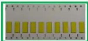
natural_image
Close-up of yellow rectangular electronic components arranged in a row, with no visible text or symbols.Juist
natural_image
Pure diagram of a grid with red X-shaped lines and yellow bars, no text or symbols presentOnjuist
natural_image
Close-up of a striped pattern with two red-circled highlights (no text or symbols visible)Gekrulde randen
natural_image
Close-up of a yellow panel with black buttons and a red oval highlight (no text or symbols)Beschadigde ladder
natural_image
Close-up of a striped electronic component with a red oval highlighting a small feature (no text or symbols visible)natural_image
Close-up of hands operating a blue industrial machine with a red arrow pointing to a component labeled 'BRADY' (no text or symbols on the machine itself)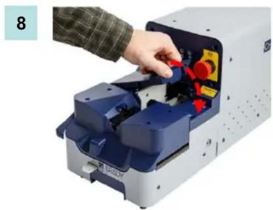
natural_image
Person operating a blue and red industrial machine with control panel (no visible text or symbols)
WAARSCHUWING
2
natural_image
Close-up of a hand inserting a cable into a blue mechanical component with a red arrow indicating direction (no text or symbols visible)natural_image
Close-up of a brown leather shoe and a small black electronic device with a cable, placed on a plain surface (no visible text or symbols)4
natural_image
Close-up of a hand using a tool to adjust or install a blue mechanical component, with no visible text or symbols.natural_image
Close-up of a yellow and white striped film strip being processed by industrial machinery, with no visible text or symbols.natural_image
Close-up of a mechanical assembly with yellow strips and green control knobs, no visible text or symbolsnatural_image
Close-up of a mechanical assembly with green and yellow components, no visible text or symbolsBrady Worldwide, Inc.
6555 West Good Hope Road
BSP45 Sleeve Applicator
natural_image
Exterior view of a modern industrial machine with blue and silver casing, connected to cables and sensors (no visible text or symbols)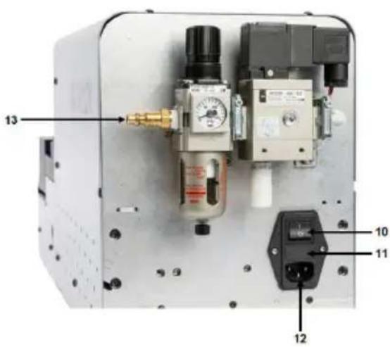
natural_image
Interior view of a mechanical device with pressure gauges, tubing, and a black electrical outlet (no visible text or symbols)natural_image
Close-up of a hand pointing at a control panel with buttons and indicator lights (no visible text or symbols)2
natural_image
Close-up of a mechanical component with two red-circled features, no visible text or symbolsnatural_image
Close-up of a hand inserting a small black plastic component into a blue electronic device casing (no visible text or symbols)4
natural_image
Close-up of a hand pressing a button on a machine control panel (no visible text or symbols)natural_image
Close-up of a mechanical assembly with blue components and a yellow label (no readable text or symbols)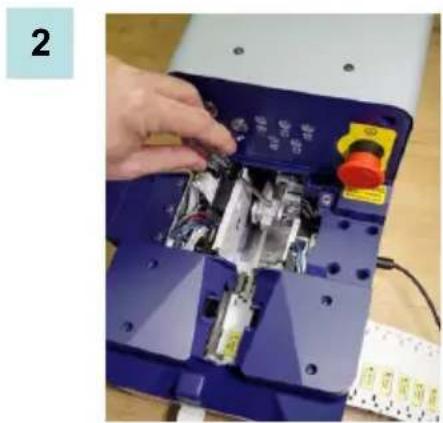
natural_image
Close-up of a hand installing or adjusting an electronic device with visible internal components and wiring (no text or symbols)natural_image
Close-up of a hand using a blue industrial machine to adjust or install a mechanical component (no visible text or symbols)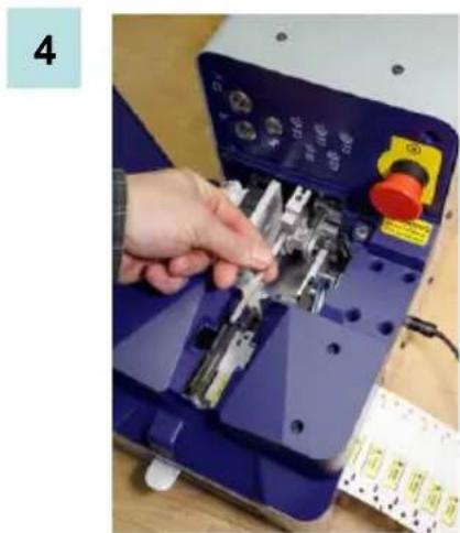
natural_image
Close-up of a hand using a small electronic device to adjust internal components (no visible text or symbols)natural_image
Close-up of a hand inserting a blue plastic component into a white industrial machine, with red arrows indicating the process (no visible text or symbols)natural_image
Close-up of a BALOY industrial machine with a hand inserting a component, showing no visible text or symbols.natural_image
Close-up of a robotic arm interacting with a mechanical device (no visible text or symbols)4

natural_image
Close-up of a mechanical device with yellow and black components, no visible text or symbols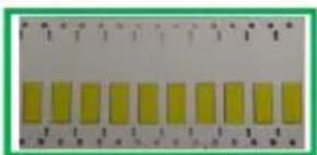
natural_image
Row of yellow rectangular blocks on a white background, no text or symbols visibleCorrecto
natural_image
Pure electrical circuit lines without any symbolsIncorrecto
natural_image
Close-up of a striped fabric with two red-circled highlights (no text or symbols visible)Bordes levantados
natural_image
Close-up of a yellow panel with a red oval highlight on the right side (no text or symbols visible)natural_image
Close-up of a patterned surface with black and white stripes, no visible text or symbolsEscalera dañada
natural_image
Close-up of a striped electronic component with a red circle highlighting a small white object (no visible text or symbols)natural_image
Close-up of a computer motherboard with multiple electronic components and mounting holes (no visible text or symbols)6
natural_image
Close-up of a brown leather shoe and a small black electronic device on a flat surface (no visible text or symbols)4
natural_image
Close-up of a hand using a tool to adjust or install a blue mechanical component (no visible text or symbols)natural_image
Close-up of a yellow and white striped film strip being processed by industrial machinery, with no visible text or symbols.natural_image
Close-up of a mechanical assembly with yellow and green components, no visible text or symbolsnatural_image
Close-up of a mechanical assembly with green and yellow components, no visible text or symbolsBrady Worldwide Inc.
6555 West Good Hope Road
Milwaukee, WI 53223, USA
Telefon: +414-358-6600 (inom USA)
Fax: 414-438-6958
FÖRENTA STATERNA
FCC-meddelande - endast USA
Waste Electrical and Electronic Equipment Directive
Applicera hylsa (IN-PEDAL-UPP). 10
Stoppa appliceringen 11
natural_image
Exterior view of a Brudy robotic device with blue and silver casing, connected to cables and accessories (no visible text or symbols)Registrera din hylsapplikator
natural_image
Close-up of a mechanical pressure regulator device with attached gauges and ports (no visible text or symbols)
natural_image
Exterior view of a modern robotic device with blue components and a black sensor module (no visible text or symbols)natural_image
Interior view of a mechanical control panel with pressure gauges, tubing, and a black electrical outlet (no visible text or symbols)natural_image
Close-up of a hand pointing at a control panel with buttons and indicators (no readable text or symbols)2
natural_image
Close-up of a mechanical component with two red-circled features, no visible text or symbolsnatural_image
Close-up of a hand inserting a small black plastic component into a blue plastic housing (no text or symbols visible)4
natural_image
Close-up of a hand pointing at a control panel with buttons and a red indicator (no visible text or symbols)natural_image
Close-up of a mechanical assembly with blue components and a yellow label (no readable text or symbols)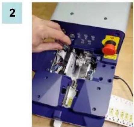
natural_image
Close-up of a hand inserting a small electronic component into a blue electronic device casing (no visible text or symbols)natural_image
Hand operating a blue industrial machine with a tool, no visible text or symbols on the device itself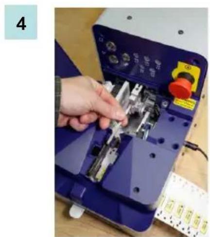
natural_image
Hand operating a blue electronic device with a hand adjusting its internal components (no visible text or symbols)natural_image
Close-up of a hand inserting a component into a white industrial machine with blue modules and a red cable (no visible text or symbols)natural_image
Close-up of a BALCH industrial machine with a hand inserting a component, showing no visible text or symbols.natural_image
Close-up of a hand pressing a yellow component on a mechanical device (no visible text or symbols)4
natural_image
Close-up of a mechanical device with yellow buttons and a red circle highlighting a specific area (no visible text or symbols)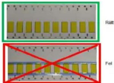
natural_image
Close-up of a striped fabric with two red-circled regions highlighting specific areas (no text or symbols visible)Böjda kanter
natural_image
Close-up of a yellow panel with black base and red oval highlight (no text or symbols)Extrem vinkelskäming
natural_image
Close-up of striped fabric with a red oval highlight on the surface (no text or symbols visible)Skadad stege

natural_image
Close-up of a striped electronic component with a red oval highlighting a small feature (no text or symbols visible)natural_image
Close-up of a mechanical device with multiple yellow and black components, no visible text or symbols6
Applicera hylsa (IN-PEDAL-UPP).
natural_image
Close-up of a hand inserting a cable into a blue industrial machine component, with no visible text or symbols.natural_image
Close-up of a brown leather shoe being placed next to a small black electronic device with a cable (no visible text or symbols)4
natural_image
Close-up of a hand using a tool to adjust or install a blue mechanical component (no visible text or symbols)Stoppa appliceringen
natural_image
Close-up of a yellow and white striped film strip being processed by industrial machinery, with no visible text or symbols.natural_image
Close-up of a mechanical assembly with yellow strips and green control knobs, no visible text or symbolsnatural_image
Close-up of a mechanical assembly with green and yellow components, no visible text or symbolsBrady Worldwide Inc.
6555 West Good Hope Road
Milwaukee, WI 53223 U.S.A.
Telephone: 414-358-6600 USA Domestic
Facsimile: 414-438-6958
Websites
For repair or technical assistance, go to your regional Brady Technical Support website:
• United States: www.bradyid.com
• Europe: www.bradyeurope.com
• Asia Pacific: www.bradycorp.com
• South Asia: http://www.bradyid.com.sg
• Australia: http://www.bradyid.com.au
• Canada: www.bradycanada.ca
• Latin American: www.bradylatinamerica.com
• Brazil: www.brady.com.br
Phone Numbers
• 1-800-643-8766 (USA)
• 1-800-263-6179 (Canada)
• +44 333 333 1111 (Europe)
• 44 1295 228 205 (UK)
• 1-800-212-8181 (Mexico)
• +55 11 4166-1500 ext 5 (Brazil)
• 1-866-748-4424 (Latin America)
• 1-800-212-8181 (Central America)
• 1 800 644 834 (Australia)
• 65-64777261 (South Asia)



- Copyright
- Trademarks
- UNITED STATES
- FCC Notice - US Only
- INDUSTRY CANADA
- EUROPE
- Waste Electrical and Electronic Equipment Directive
- RoHS Directive 2011/65/EU
- Intended Use
- Warnings:
- Cautions:
- BSP45 Sleeve Applicator
- Media Specifications
- BSP45 Footswitch
- Technical Support Numbers/On-line Help
- Repair and Replacement Parts
- Unpack Your Applicator
- Register Your Sleeve Applicator
- Sleeve Applicator Setup
- Changing Dies/Sleeve Size ENGLISH
- Changing Dies/Sleeve Size
- Loading Media ENGLISH
- WARNINGWARNINGWARNING
- Recovering from a Dropped Sleeve
- Cleaning the Applicator
- Fuse
- Cleaning Dies
- Troubleshooting
- Recovering from Errors
- Appendix A - Loading Material on BBP72 Printer ENGLISH
- Appendix A - Loading Material on BBP72 Printer
- Template Side #1 (first side to print for 1- and 2-sided printing)
- Template Side #2 (second side for double-sided printing)
- USA
- Etikettenhüllen-Applikator registrieren
- Uw sleeve applicator registreren
- Instellen sleeve applicator
- Media laden
- WAARSCHUWING
- FÖRENTA STATERNA
- FCC-meddelande - endast USA
- Registrera din hylsapplikator
- Applicera hylsa (IN-PEDAL-UPP).
- Stoppa appliceringen
- Brady Worldwide Inc.
- Websites
- Phone Numbers
Brand : BRADY
Model : BSP45
Category : Label printer