TAPX08W5HWT - Air Conditioning TOSHIBA - Free user manual and instructions
Find the device manual for free TAPX08W5HWT TOSHIBA in PDF.

User questions about TAPX08W5HWT TOSHIBA
0 question about this device. Answer the ones you know or ask your own.
Ask a new question about this device
Download the instructions for your Air Conditioning in PDF format for free! Find your manual TAPX08W5HWT - TOSHIBA and take your electronic device back in hand. On this page are published all the documents necessary for the use of your device. TAPX08W5HWT by TOSHIBA.
USER MANUAL TAPX08W5HWT TOSHIBA
natural_image
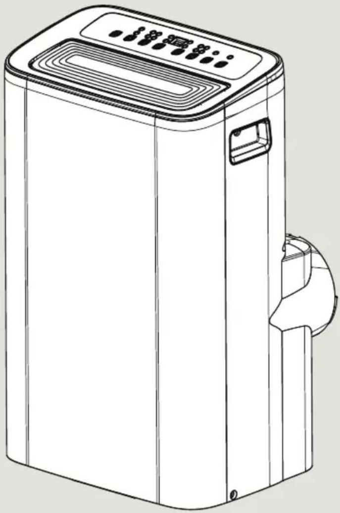
Line drawing of a portable air purifier with control panel and side arm (no text or symbols)USER MANUAL
Portable Type
Room Air Conditioner
TAPX08W5HWT
version A - 09202 us4toshiba-lifestyle.com
Safety Precautions
Before You Get Started
Installation Instructions
Operating Instructions
Cleaning & Maintenance
Troubleshooting Tips
Remote Control and App Instructions
Warning notices: Before using this product, please read this manual carefully and keep it for future reference.
The design and specifications are subject to change without prior notice for product improvement. Consult with your dealer or the manufacturer for details.
User Manual
Safety Precautions 3
Before You Get Started 13
Installation Instructions 15
Operating Instructions 23
Cleaning & Maintenance 26
Troubleshooting Tips 28
Remote Control and App Instructions 29
Read This Manual
Inside you'll find many helpful hints on how to use and maintain your air conditioner properly. Just a little preventive care on your part can save you a great deal of time and money over the life of your air conditioner. You'll find many answers to common problems in the troubleshooting tips - you should be able to fix most of them quickly before calling service. These instructions may not cover every possible condition of use, so common sense and attention to safety is required when installing, operating and maintaining this product.

CAUTION
• For support, please call the Service Center at 1-855-238-5607.
- This appliance is not intended for use by persons (including children) with reduced physical, sensory or mental capabilities or lack of experience and knowledge, unless they have been given supervision or instruction concerning use of the appliance by a person responsible for their safety.
• Children should be supervised to ensure that they do not play with the air conditioner.
• The appliance shall be installed in accordance with national wiring regulations.
- Do not operate your air conditioner in a humid room such as a bathroom or laundry room.
SAFETY PRECAUTIONS
Must read the warning message.
Read Safety Precautions Before Operation and Installation
To prevent death or injury to the user or other people and property damage, the following instructions must be followed.
Incorrect operation due to ignoring of instructions may cause death, harm or damage.
Explanation of Symbols

WARNING
This symbol indicates the possibility of personnel injury or loss of life.

CAUTION
This symbol indicates the possibility of property damage or serious consequences.
Electronic Work

WARNING:
BEFORE PERFORMING ANY ELECTRICAL OR WIRING WORK, TURN OFF THE MAIN POWER TO THE SYSTEM.
Electronic Type
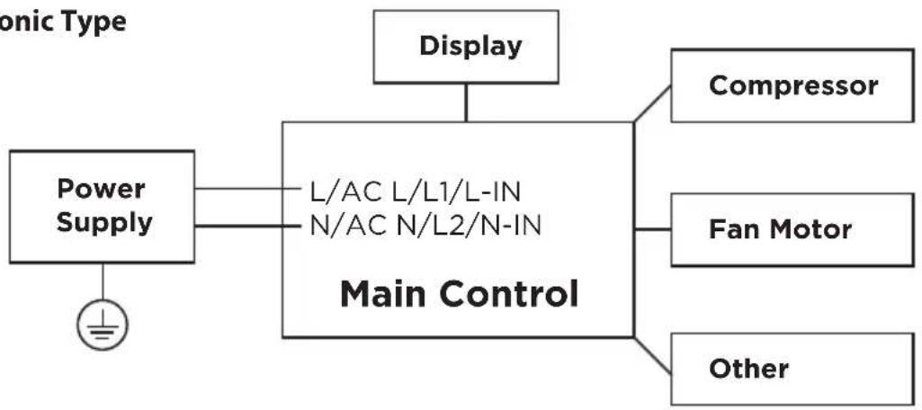
flowchart
graph TD
    A["Power Supply"] --> B["L/AC L/L1/L-IN N/AC N/L2/N-IN Main Control"]
    C["Display"] --> B
    D["Compressor"] --> B
    E["Fan Motor"] --> B
    F["Other"] --> B

NOTICE:
Please strictly follow the wiring label attached to the machine for all wiring connections. The wiring diagram may vary for different unit. Please refer to the wiring diagram on the machine you have purchased. The above wiring diagram is a simplified version for preliminary illustration purposes only.
Operation of Current Device

text_image
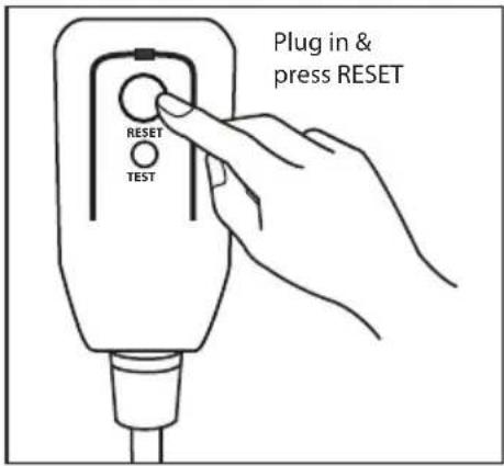
Plug in & press RESET RESET TESTThe power supply cord contains a measurement current device that senses damage to the power cord.
Test your power supply cord as follows:
- Plug in the air conditioner.
- The power supply cord will have TWO buttons on the plug head. Press the TEST button. You will notice a click as the RESET button pops out.
- Press the RESET Button. You will notice a click as the button engages.
- The power supply cord is now supplying electricity to the unit. (On some products this is also indicated by a light on the plug head.)
NOTICE
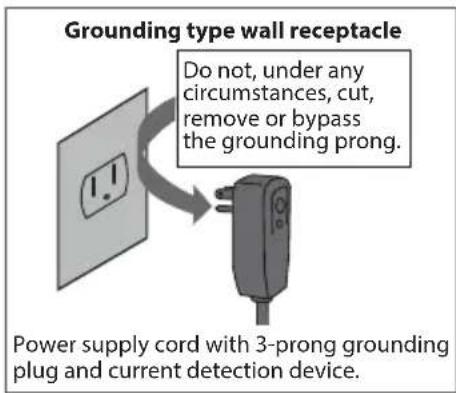
text_image
Grounding type wall receptacle Do not, under any circumstances, cut, remove or bypass the grounding prong. Power supply cord with 3-prong grounding plug and current detection device.The power supply cord with this air conditioner contains a current detection device designed to reduce the risk of fire.
In the event that the power supply cord is damaged, it can not be repaired. It must be replaced with a cord from the manufacturer.
NOTICE
- Do not use this device to turn the unit on or off.
• Always make sure the RESET button is pushed in for correct operation. - The power supply must be replaced if it fails to reset when either the TEST button is pushed, or it can not be reset. Please contact Customer Service.

WARNING
• Installation must be performed according to the installation instructions. Improper installation can cause water leakage, electrical shock, or fire.
- Use only the included accessories and parts, and specified tools for the installation. Using nonstandard parts can cause water leakage, electrical shock, fire, and injury or property damage.
- Make sure that the outlet you are using is grounded and has the appropriate voltage. The power cord is equipped with a three-prong grounding plug to protect against shock. Voltage information can be found on the nameplate of the unit.
- Your unit must be used in a properly grounded wall receptacle. If the wall receptacle you intend to use is not adequately grounded or protected by a time delay fuse or circuit breaker (the fuse or circuit breaker needed is determined by the maximum current of the unit. The maximum current is indicated on the nameplate located on unit), have a qualified electrician install the proper receptacle.
- Do not touch the unit with wet or damp hands or when barefoot.
- If the air conditioner is knocked over during use, turn off the unit and unplug it from the main power supply immediately. Visually inspect the unit to ensure there is no damage. If you suspect the unit has been damaged, contact a technician or customer service for assistance.
- In a thunderstorm, the power must be cut off to avoid damage to the machine due to lightning.
- Your air conditioner should be used in such a way that it is protected from moisture. e.g. condensation, splashed water, etc. Do not place or store your air conditioner where it can fall or be pulled into water or any other liquid. Unplug immediately if it occurs.
• Install the unit on a flat, sturdy surface. Failure to do so could result in damage or excessive noise and vibration.
- The unit must be kept free from obstruction to ensure proper function and to mitigate safety hazards.
- Do not modify the length of the power cord or use an extension cord to power the unit.
- Do not share a single outlet with other electrical appliances. Improper power supply can cause fire or electrical shock.
- Do not install your air conditioner in a wet room such as a bathroom or laundry room. Too much exposure to water can cause electrical components to short circuit.
- Do not install the unit in a location that may be exposed to combustible gas, as this could cause fire.
- The unit has wheels to facilitate moving. Make sure not to use the wheels on thick carpet or to roll over objects, as these could cause tipping.
- Do not operate a unit that it has been dropped or damaged.
- The appliance with electric heater shall have at least 1 meter space to the combustible materials.
- All wiring must be performed strictly in accordance with the wiring diagram located inside of the unit.
- The unit's circuit board(PCB) is designed with a fuse to provide overcurrent protection. The specifications of the fuse are printed on the circuit board, such as: T 3.15A/250V, etc.
- When the water drainage function is not in use, keep the upper and the lower drain plug firmly to the unit to get rid of choking. When the drain plug is not in use, keep it carefully to prevent children from choking.

CAUTION
- This appliance is not intended for use by persons (including children) with reduced physical, sensory or mental capabilities or lack of experience and knowledge, unless they have been given supervision or instruction concerning use of the appliance by a person responsible for their safety. Children should be supervised to ensure that they do not play with the appliance. Children must be supervised around the unit at all times.
- If the supply cord is damaged, it must be replaced by the manufacturer, its service agent or similarly qualified persons in order to avoid a hazard.
- Do not use this product for functions other than those described in this instruction manual.
- Before cleaning, turn off the power and unplug the unit.
- Disconnect the power if strange sounds, smell, or smoke comes from it.
- Do not press the buttons on the control panel with anything other than your fingers.
- Do not remove any fixed covers. Never use this appliance if it is not working properly, or if it has been dropped or damaged.
- Do not operate or stop the unit by inserting or pulling out the power cord plug.
- Do not use hazardous chemicals to clean or come into contact with the unit. Do not use the unit in the presence of inflammable substances or vapour such as alcohol, insecticides, petrol, etc.
- Prior to cleaning or other maintenance, the appliance must be disconnected from the supply mains.
- Do not remove any fixed covers. Never use this appliance if it is not working properly, or if it has been dropped or damaged.
- Do not run cord under carpeting. Do not cover cord with throw rugs, runners, or similar coverings. Do not route cord under furniture or appliances. Arrange cord away from traffic area and where it will not be tripped over.
- Do not operate unit with a damaged cord, plug, power fuse or circuit breaker. Discard unit or return to an authorized service facility for examination and/or repair.
- To reduce the risk of fire or electric shock, do not use this fan with any solid-state speed control device.
- The appliance shall be installed in accordance with national wiring regulations.
- Contact the authorized service technician for repair or maintenance of this unit.
- Do not cover or obstruct the inlet or outlet grilles.
- Always transport your air conditioner in a vertical position and stand on a stable, level surface during use.
• Always contact a qualified person to carry out repairs. If the damaged power supply cord must be replaced with a new power supply cord obtained from the product manufacturer and not repaired. - Hold the plug by the head of the power plug when taking it out.
- Turn off the product when not in use.

text_image
A2LCAUTION:
Risk of fire
flammable materials
IMPORTANT NOTE: Read this manual carefully before installing or operating your new appliance unit.
Make sure to save this manual for future reference.
Explanation of symbols displayed on the unit
| CAUTION | This symbol shows that the operation manual should be read carefully. | |
| CAUTION | This symbol shows that a service personnel should be handling this equipment with reference to the installation manual. | |
| CAUTION | This symbol shows that information is available such as the operating manual or installation manual. |
WARNING:
- Servicing shall only be performed as recommended by the equipment manufacturer. Maintenance and repair requiring the assistance of other skilled personnel shall be carried out under the supervision of the person competent in the use of flammable refrigerants.
- DO NOT modify the length of the power cord or use an extension cord to power the unit.
- DO NOT share a single outlet with other electrical appliances. Improper power supply can cause fire or electrical shock.
- Please follow the instruction carefully to handle, install, clear, service the appliance to avoid any damage or hazard.
Flammable Refrigerant R32 is used within appliance.
- When maintaining or disposing the appliance, the refrigerant (R32) shall be recovered properly, shall not discharge to air directly.
• Compliance with national gas regulations shall be observed. - Keep ventilation openings clear of obstruction.
- The appliance shall be stored so as to prevent mechanical damage from occurring.
- A warning that the appliance shall be stored in a well-ventilated area where the room size corresponds to the room area as specified for operation.
- Any person who is involved with working on or breaking into a refrigerant circuit should hold a current valid certificate from an industry-accredited assessment authority, which authorises their competence to handle refrigerants safely in accordance with an industry recognised assessment specification. All training shall follow the ANNEX HH requirements of UL 60335-2-40 4th Edition.
Examples for such working procedures are:
- breaking into the refrigerating circuit;
- opening of sealed components;
-
opening of ventilated enclosures.
-
No open fire or device like switch which may generate spark/arcing shall be around appliance to avoid causing ignition of the flammable refrigerant used.
Please follow the instruction carefully to store or maintain the appliance to prevent mechanical damage from occurring. - Do not use means to accelerate the defrosting process or to clean, other than those recommended by the manufacturer.
- The appliance shall be stored in a room without continuously operating ignition sources (for example: open flames, an operating gas appliance) and ignition sources or (for example: an operating electric heater) close to the appliance.
- Do not pierce or burn.
- Be aware that the refrigerants may not contain an odour.
1. Transport of equipment containing flammable refrigerants
See transport regulations.
2. Marking of equipment using signs
See local regulations.
3. Disposal of equipment using flammable refrigerants
See national regulations.
4. Storage of equipment/appliances
The storage of the appliance should be in accordance with the applicable regulations or instructions, whichever is more stringent.
5. Storage of packed (unsold) equipment
Storage package protection should be constructed such that mechanical damage to the equipment inside the package will not cause a leak of the refrigerant charge. The maximum number of pieces of equipment permitted to be stored together will be determined by local regulations.
6. Information on servicing
1) Checks to the area
Prior to beginning work on systems containing flammable refrigerants, safety checks are necessary to ensure that the risk of ignition is minimised. For repair to the refrigerating system, the following precautions shall be complied with prior to conducting work on the system.
2) Work procedure
Work shall be undertaken under a controlled procedure so as to minimise the risk of a flammable gas or vapour being present while the work is being performed.
3) General work area
All maintenance staff and others working in the local area shall be instructed on the nature of work being carried out. Work in confined spaces shall be avoided. The area around the workspace shall be sectioned off. Ensure that the conditions within the area have been made safe by control of flammable material.
4) Checking for presence of refrigerant
The area shall be checked with an appropriate refrigerating detector prior to and during work, to ensure the technician is aware of potentially flammable atmospheres. Ensure that the leak detection equipment being used is suitable for use with flammable refrigerants, i.e. non-sparking, adequately sealed or intrinsically safe.
5) Presence of fire extinguisher
If any hot work is to be conducted on the refrigeration equipment or any associated parts, appropriate fire extinguishing equipment shall be available to hand. Have a dry powder or CO_2 fire extinguisher adjacent to the charging area.
6) No ignition sources
No person carrying out work in relation to a refrigerating system which involves exposing any pipe work that contains or has contained flammable refrigerant shall use any sources of ignition in such a manner that it may lead to the risk of fire or explosion. All possible ignition sources, including cigarette smoking, should be kept sufficiently far away from the site of installation, repairing, removing and disposal, during which flammable refrigerant can possibly be released to the surrounding space. Prior to work taking place, the area around the equipment is to be surveyed to make sure that there are no flammable hazards or ignition risks. No Smoking signs shall be displayed.
7) ventilated area
Ensure that the area is in the open or that it is adequately ventilated before breaking into the system or conducting any hot work. A degree of ventilation shall continue during the period that the work is carried out. The ventilation should safely disperse any released refrigerant and preferably expel it externally into the atmosphere.
8) Checks to the refrigerating equipment
Where electrical components are being changed, they shall be fit for the purpose and to the correct specifications. At all times the manufacturer's maintenance and service guidelines shall be followed. If in doubt consult the manufacturer's technical department for assistance. The following checks shall be applied to installations using flammable refrigerants: the actual refrigerant charge is in accordance with the room size within which the refrigerant containing parts are installed; the ventilation machinery and outlets are operating adequately and are not obstructed; if an indirect refrigerating circuit is being used, the secondary circuit shall be checked for the presence of refrigerant; marking to the equipment continues to be visible and legible.
Markings and signs that are illegible shall be corrected; and refrigerating pipe or components are installed in a position where they are unlikely to be exposed to any substance which may corrode refrigerant containing components, unless the components are constructed of materials which are inherently resistant to being corroded or are suitably protected against being so corroded.
9) Checks to electrical devices
Repair and maintenance to electrical components shall include initial safety checks and component inspection procedures. If a fault exists that could compromise safety, then no electrical supply shall be connected to the circuit until it is satisfactorily dealt with. If the fault cannot be corrected immediately but it is necessary to continue operation, an adequate temporary solution shall be used.
This shall be reported to the owner of the equipment so all parties are advised. Initial safety checks shall include: That capacitors are discharged: this shall be done in a safe manner to avoid possibility of sparking; that there no live electrical components and wiring are exposed while charging, recovering or purging the system; that there is continuity of earth bonding.
-
Sealed electrical components shall be replaced.
-
Intrinsically safe components must be replaced.
-
Cabling
Check that cabling will not be subject to wear, corrosion, excessive pressure, vibration, sharp edges or any other adverse environmental effects. The check shall also take into account the effects of aging or continual vibration from sources such as compressors or fans.
- Detection of flammable refrigerants
Under no circumstances shall potential sources of ignition be used in the searching for or detection of refrigerant leaks. A halide torch (or any other detector using a naked flame) shall not be used.
The following leak detection methods are deemed acceptable for systems containing flammable refrigerants. Electronic leak detectors shall be used to detect flammable refrigerants, but the sensitivity may not be adequate, or may need re-calibration. (Detection equipment shall be calibrated in a refrigerant-free area.) Ensure that the detector is not a potential source of ignition and is suitable for the refrigerant used. Leak detection equipment shall be set at a percentage of the LFL of the refrigerant and shall be calibrated to the refrigerant employed and the appropriate percentage of gas (25 % maximum) is confirmed. Leak detection fluids are suitable for use with most refrigerants but the use of detergents containing chlorine shall be avoided as the chlorine may react with the refrigerant and corrode the copper pipe-work. If a leak is suspected, all naked flames shall be removed/ extinguished. If a leakage of refrigerant is found which requires brazing, all of the refrigerant shall be recovered from the system, or isolated (by means of shut off valves) in a part of the system remote from the leak. Removal of refrigerant shall be according to Removal and evacuation.
- Removal and evacuation
When breaking into the refrigerant circuit to make repairs—or for any other purpose - conventional procedures shall be used. However, for flammable refrigerants it is important that best practice be followed, since flammability is a consideration. The following procedure shall be adhered to:
- Safely remove refrigerant following local and national regulations;
- Evacuate;
- Purge the circuit with inert gas (optional for A2L);
- Evacuate (optional for A2L);
- continuously flush or purge with inert gas when using flame to open circuit; and - open the circuit.
The refrigerant charge shall be recovered into the correct recovery cylinders if venting is not allowed by local and national codes. For appliances containing flammable refrigerants, the system shall be purged with oxygen-free nitrogen to render the appliance safe for flammable refrigerants. This process might need to be repeated several times.
Compressed air or oxygen shall not be used for purging refrigerant systems.
For appliances containing flammable refrigerants, refrigerants purging shall be achieved by breaking the vacuum in the system with oxygen-free nitrogen and continuing to fill until the working pressure is achieved, then venting to atmosphere, and finally pulling down to a vacuum (optional for A2L). This process shall be repeated until no refrigerant is within the system (optional for A2L). When the final oxygen-free nitrogen charge is used, the system shall be vented down to atmospheric pressure to enable work to take place. The outlet for the vacuum pump shall not be close to any potential ignition sources, and ventilation shall be available.
12. Charging procedures
In addition to conventional charging procedures, the following requirements shall be followed. Ensure that contamination of different refrigerants does not occur when using charging equipment. Hoses or lines shall be as short as possible to minimise the amount of refrigerant contained in them. Cylinders shall be kept in an appropriate position according to the instructions. Ensure that the refrigeration system is earthed prior to charging the system with refrigerant. Label the system when charging is complete (if not already). Extreme care shall be taken not to overfill the refrigeration system. Prior to recharging the system it shall be pressure tested with OFN. The system shall be leak tested on completion of charging but prior to commissioning. A follow up leak test shall be carried out prior to leaving the site.
13. Decommissioning
Before carrying out this procedure, it is essential that the technician is completely familiar with the equipment and all its detail. It is recommended good practice that all refrigerants are recovered safely. Prior to the task being carried out, an oil and refrigerant sample shall be taken in case analysis is required prior to re-use of reclaimed refrigerant. It is essential that electrical power is available before the task is commenced.
a) Become familiar with the equipment and its operation.
b) Isolate system electrically.
c) Before attempting the procedure ensure that: Mechanical handling equipment is available, if required, for handling refrigerant cylinders; all personal protective equipment is available and being used correctly; the recovery process is supervised at all times by a competent person; recovery equipment and cylinders conform to the appropriate standards.
d) Pump down refrigerant system, if possible.
e) If a vacuum is not possible, make a manifold so that refrigerant can be removed from various parts of the system.
f) Make sure that cylinder is situated on the scales before recovery takes place.
g) Start the recovery machine and operate in accordance with manufacturer's instructions.
h) Do not overfill cylinders. (No more than 80 % volume liquid charge).
i) Do not exceed the maximum working pressure of the cylinder, even temporarily.
j) When the cylinders have been filled correctly and the process completed, make sure that the cylinders and the equipment are removed from site promptly and all isolation valves on the equipment are closed off.
k) Recovered refrigerant shall not be charged into another refrigeration system unless it has been cleaned and checked.
14. Labeling
Equipment shall be labelled stating that it has been de-commissioned and emptied of refrigerant. The label shall be dated and signed. Ensure that there are labels on the equipment stating the equipment contains flammable refrigerant.
15. Recovery
When removing refrigerant from a system, either for servicing or decommissioning, it is recommended good practice that all refrigerants are removed safely. When transferring refrigerant into cylinders, ensure that only appropriate refrigerant recovery cylinders are employed. Ensure that the correct number of cylinders for holding the total system charge is available. All cylinders to be used are designated for the recovered refrigerant and labelled for that refrigerant (i.e. special cylinders for the recovery of refrigerant). Cylinders shall be complete with pressure relief valve and associated shut-off valves in good working order. Empty recovery cylinders are evacuated and, if possible, cooled before recovery occurs. The recovery equipment shall be in good working order with a set of instructions concerning the equipment that is at hand and shall be suitable for the recovery of the flammable refrigerant. If in doubt, the manufacturer should be consulted. In addition, a set of calibrated weighing scales shall be available and in good working order. Hoses shall be complete with leak-free disconnect couplings and in good condition.
The recovered refrigerant shall be processed according to local legislation in the correct recovery cylinder, and the relevant waste transfer note arranged. Do not mix refrigerants in recovery units and especially not in cylinders. If compressors or compressor oils are to be removed, ensure that they have been evacuated to an acceptable level to make certain that flammable refrigerant does not remain within the lubricant. The compressor body shall not be heated by an open flame or other ignition sources to accelerate this process. When oil is drained from a system, it shall be carried out safely.
BEFORE YOU GET STARTED
Preparations Before Installation
The installation must be carried out in strict accordance with the instructions in this manual.

Installing your AC should take about 30 minutes.

We recommend doing this with a helper.

We're here if you need us, please contact 1-855-238-5607
Ambient Temperature Range For Unit Operating:
| Mode Temperature Range | |
| Cool 16~35°C (60~95°F) | |
| Dry 13~35°C (55~95°F) | |
| Heat (pump heat mode) 5~30°C (41~86°F) | |
| Heat (electrical heat mode) ≤ 30°C (86°F) | |
Know your Portable Air Conditioner
Energy Rating Information
The energy rating and noise information for this unit is based on the standard installation using an un-extended exhaust duct without window slider adaptor (as shown in the Installation section of this manual). With the unit operating on COOL MODE and HIGH FAN SPEED.
NOTICE
We recommend operating the unit at room temperature below 35^ C( 95^ F). Since there is a risk that the unit with 3 meters extended exhaust duct would not work at room temperature above 35^ C( 95^ F) under some extreme conditions, such as the lower air intake be blocked for 50%.
How to Stay Cool with a New Portable Air Conditioner (For the models comply with the requirements of Department Of Energy in US)
Because of a new federal test procedure for Portable Air Conditioners, you may notice that the cooling capacity claims on portable air conditioner packaging are significantly lower than that of models produced prior to 2017. This is due to changes in the test procedure, not to the portable air conditioners themselves.
What Should I Look For First When Purchasing A Portable Air Conditioner?
The right air conditioner helps you cool a room efficiently. An undersized unit won't cool adequately while one that's too large will not remove enough humidity, leaving the air feeling damp. To find the proper air conditioner, determine the square footage of the room you want to cool by multiplying the room length by its width. You also need to know the air conditioner's BTU (British Thermal Unit) rating, which indicates the amount of heat it can remove from a room. A higher number means more cooling power for a larger room. (Be sure you are comparing only newer models to each other. Older models may appear to have a higher capacity, but are actually the same). Be sure to "size up" if your portable air conditioner will be placed in a very sunny room, in a kitchen, or in a room with high ceilings. After you've found the right cooling capacity for your room, you can look at other features.
Why Newer Products Have Lower Cooling Capacity Than Older Models
Federal regulations require manufacturers to calculate cooling capacity based on a specific test procedure, which was changed just this year. Models manufactured before 2017 were tested under a different procedure and cooling capacity was measured differently in prior year's models. So, while the BTUs may be lower now, the actual cooling capacity of the air conditioners has not changed.
What is SACC?
SACC is the representative value of Seasonally Adjusted Cooling Capacity, in Btu/h, as determined in accordance with the DOE test procedure at title 10 Code of Federal Regulations (CFR) 430, subpart B, appendix CC and applicable sampling plans.
INSTALLATION INSTRUCTIONS
Product Installation Location
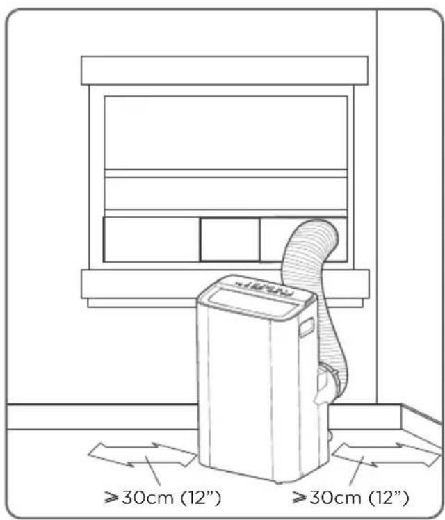
Your Installation Location Should Meet The Following Requirements:
• Make sure that you install your unit on an even surface to minimize noise and vibration.
- The unit must be installed near a grounded plug, and the Collection Tray Drain (found on the back of the unit) must be accessible.
- The unit should be located at least 30cm (12") from the nearest wall to ensure proper air conditioning. The air outlet of the unit should be at least 50cm (19.7") away from obstacles.
- DO NOT cover the Intakes, Outlets or Remote Signal Receptor of the unit, as this could cause damage to the unit.
Unit Installation Location Restricted Space Requirements
text_image
>30cm (12") ≥30cm (12)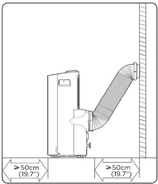
text_image
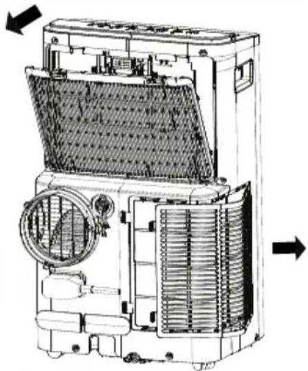
≥50cm (19.7") ≥50cm (19.7")Product Overview
NOTICE
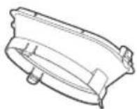
All the illustrations in the manual are for explanation purpose only. Your machine may be slightly different. The actual shape shall prevail.
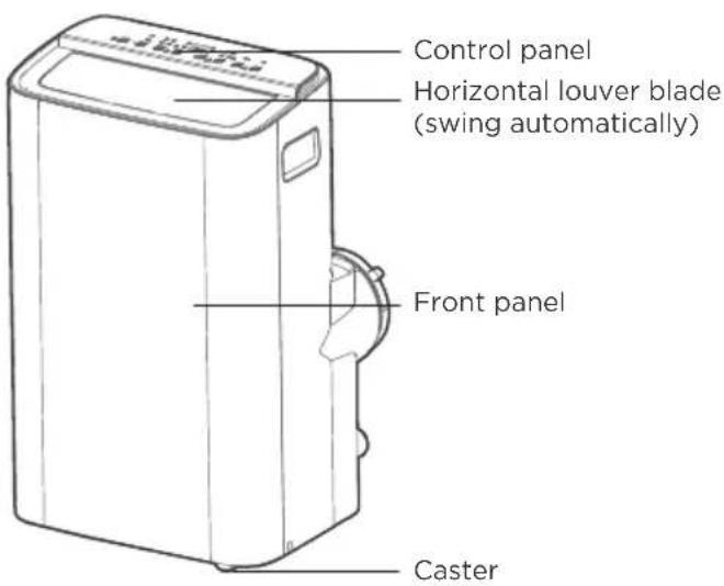
The unit can be controlled by the unit control panel alone or with the remote control.
text_image
Control panel Horizontal louver blade (swing automatically) Front panel CasterFront View Rear View
text_image
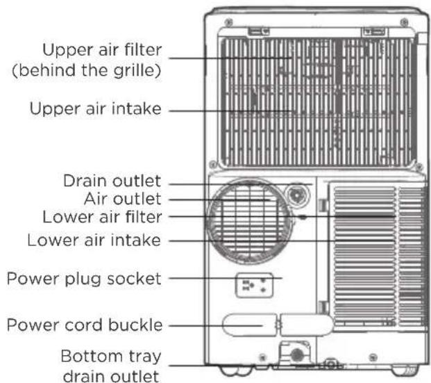
Upper air filter (behind the grille) Upper air intake Drain outlet Air outlet Lower air filter Lower air intake Power plug socket Power cord buckle Bottom tray drain outletDESIGN NOTICE
In order to ensure the optimal performance of our products, the design specifications of the unit and remote control are subject to change without prior notice.
Installation Overview
Installation Completion Display
text_image
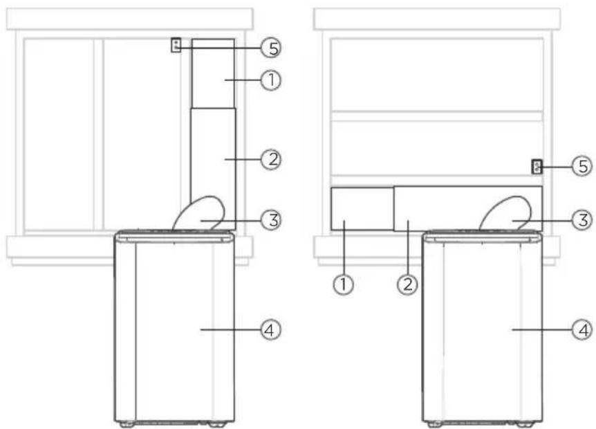
Technical diagram of a refrigerator with numbered components for identification and assembly reference.Sliding Window Installation Hung Window Installation
- Window Slider B
- Window Slider A
- Extended Exhaust Hose
- Portable Air Conditioner
- Security Bracket and 2 Screws
NOTICE
Illustrations in this manual are for explanatory purposes. The actual shape of your indoor unit may be slightly different. The actual shape shall prevail.
Tools Needed
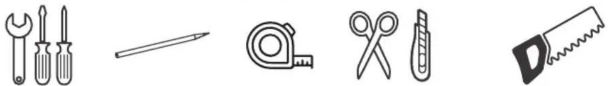
natural_image
Illustration of five different tools: wrench, screwdriver, tape measure, scissors, and saw (no text or symbols)Screwdriver & wrench
Pencil Saw (On santemodels, measure
Scissors or Knife
to shorten window adaptor for narrow windows)
Installation Accessories
NOTICE
Slight variations in design may occur.
Unit Adaptor (1 pc)
Air exhaust passage (1 pc)
Foam Seal A (Adhesive) (4 pc)
Foam Seal B (Adhesive) (2 pc)
Foam Seal C
(Non-adhesive) (2 pc)
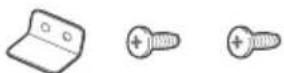
Security Bracket and 2 Screws (1 set)
Drain Hose (1 pc)
Exhaust Hose (1 pc)
Bolt (3 pc)
Power Cord
Buckle (1 pc)
Remote Controller and Battery (only for remote control models) (1 set)
natural_image
Four empty rectangular boxes with no text or symbols, containing abstract line drawings (no text or symbols)Window Sliders (1 set)
Confirm Your Window Type (Window Type And Opening Size Of Different Types)

natural_image
Simple line drawing of a window frame with three panes and a vertical stripe on the right pan (no text or symbols)Sliding Window Installation

natural_image
Simple line drawing of a rectangular frame with three horizontal bands, no text or symbols present.Hung Window Installation
For Optimal Performance In Operation
NOTICE
To ensure proper function, DO NOT overextend or bend the hose. Make sure that there is no obstacle around the air outlet of the exhaust hose (in the range of 500mm) in order to ensure the exhaust system works properly. All the illustrations in this manual are for explanation purpose only. Your air conditioner may be slightly different. The actual shape shall prevail.
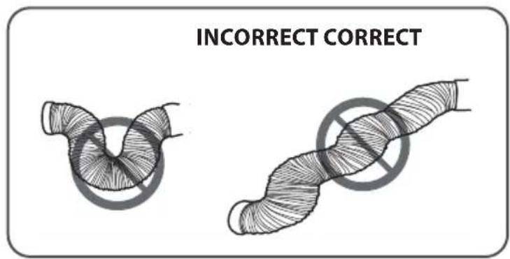
text_image
INCORRECT CORRECT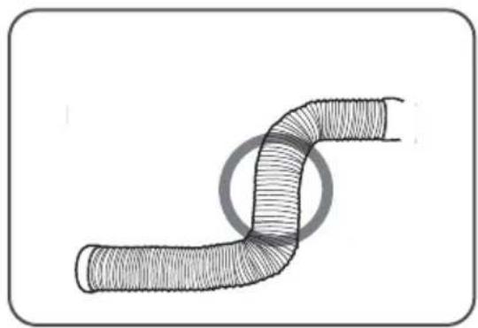
natural_image
Diagram of a bent pipe with hatched fill, no text or symbols presentExhaust Hose And Adaptors Installation
1 - The Exhaust Hose Assembly Installation (Window Type):
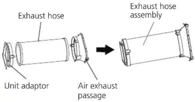
text_image
Exhaust hose Unit adaptor Air exhaust passage Exhaust hose assemblyPress the exhaust hose (or extended exhaust hose) into the window slider adaptor and unit adaptor, clamp automatically by elastic buckles of the adaptors.
NOTICE
Please install the exhaust hose assembly according to the fittings in your kit.
Connect The Adaptor To The Unit And The Window
2 - Preparing the Adjustable Window Slider:
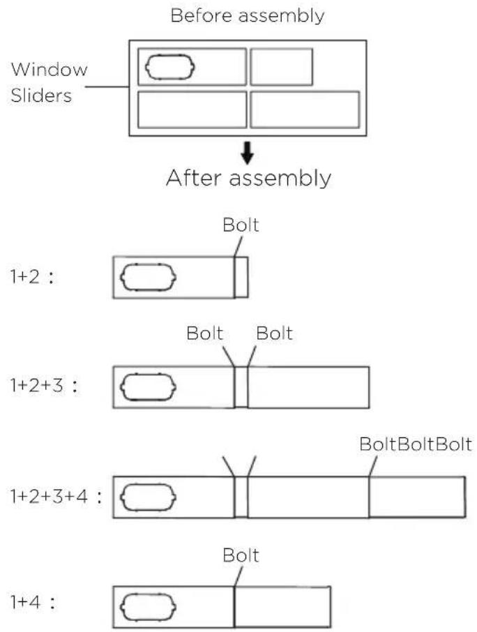
flowchart
graph TD
    A["Window Sliders"] --> B["Before assembly"]
    B --> C["After assembly"]
    subgraph "Before assembly"
        D[" "] --> E["Bolt"]
    end
    subgraph "After assembly"
        F[" "] --> G["Bolt"]
    end
    subgraph "After assembly"
        H[" "] --> I["BoltBoltBolt"]
    end
Choose the window sliders according to the size of your window. Sometimes, it needs to be cut short to meet the window size, please take extra care to cut it properly.
Use bolts to fasten the window sliders once they are adjusted to the proper length.
NOTICE
Please base your window slider installation on the accessories in your kit and the size of your window.
3 - Complete Sealing of Window:
Cut the adhesive foam seal A and B strips to the proper lengths, and attach them to the window sash and frame as shown.
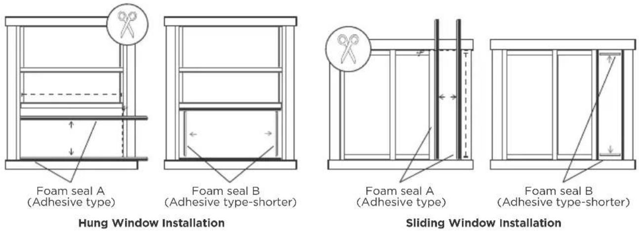
4 - Hung Window Installation:
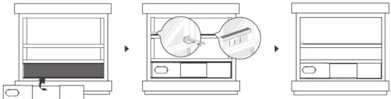
Step 1: Insert the window slider assembly into the window opening.
Step 2: Cut the non-adhesive foam seal C strip to match the width of the window. Insert the seal between the glass and the window frame to prevent air and insects from getting into the room.
Step 3: If desired, install the security bracket with 2 screws as shown.
NOTICE
Once the exhaust hose assembly and adjustable window slider are prepared, choose one of the two installation methods based on your window type.
5 - Sliding Window Installation:
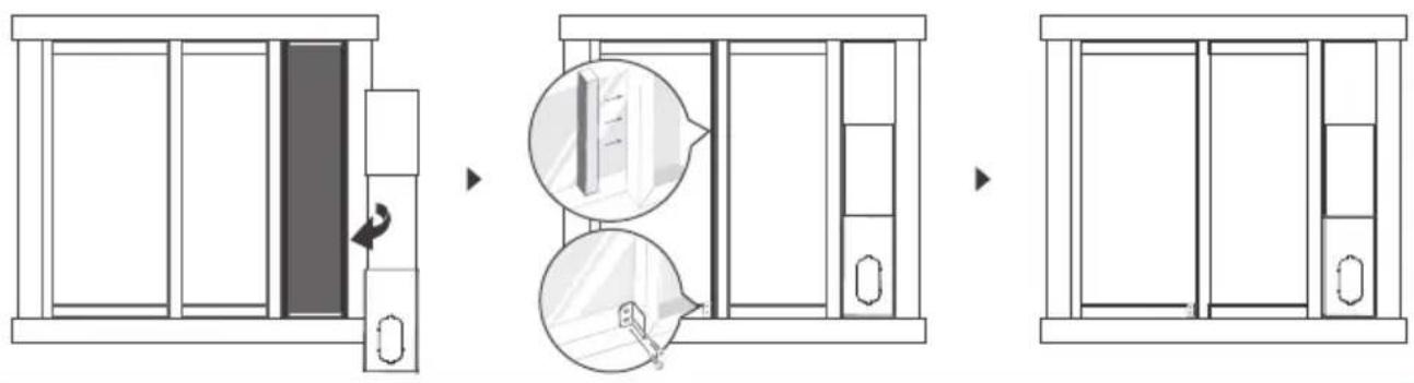
Step 1: Insert the window slider assembly into the window opening.
Step 2: Cut the non-adhesive foam seal C strip to match the height of the window. Insert the seal between the glass and the window frame to prevent air and insects from getting into the room.
Step 3: If desired, install the security bracket with 2 screws as shown.
NOTICE
Once the exhaust hose assembly and adjustable window slider are prepared, choose one of the two installation methods based on your window type.
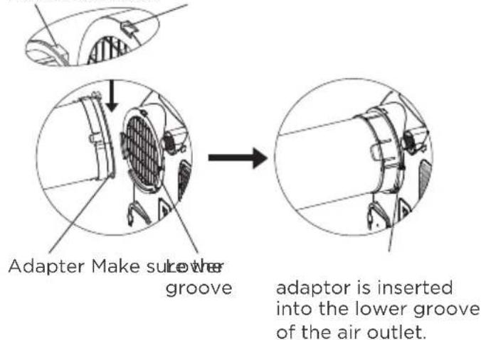
6 - Install The Exhaust Hose Assembly To The Unit:
Hook Hook Seat
text_image
Adapter Make sur lower groove adaptor is inserted into the lower groove of the air outlet.Push the exhaust hose into the air outlet opening of the unit along the arrow direction.
7 - Connect The Adaptor To The Unit And The Window:
Insert the window slider adapter into the hole of the window slider.
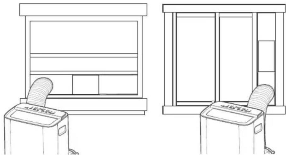
natural_image
Line drawings of two identical indoor devices with fans and doors, no text or symbols presentHung Window Installation Sliding Window Installation
OPERATING INSTRUCTIONS
Electronic Control Operating Instructions
text_image
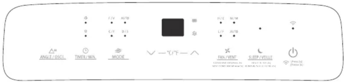
ANGLE / OSCIL TIMER / MIN. MODE - °C/°F - ^ FAN / VENT CONSOLIDATED ON VENT/CONSTANDING ON FAN / VENT CONSOLIDATED ON FAN / VENT SLEEP / VEILLE CONSOLIDATED ON FAN / VENT CONSOLIDATED ON FAN / VENT Press 10 Press 101. POWER Button
Power switch on/off.
Used to initiate the Wireless function. For the first time using the Wireless function, press and hold the POWER button for 3 seconds to initiate the Wireless connection mode. The LED DISPLAY shows 'AP' to indicate you can set Wireless connection. If connection (router) is successful within 8 minutes, the unit will exit Wireless connection mode automatically and the Wireless indicator light illuminates.
If connection fails within 8 minutes, the unit exits Wireless connection mode automatically. After Wireless connection is successful, you can press and hold POWER and DOWN (√/-) buttons at the same time for 3 seconds to turn off wireless function and the LED display shows 'OF' for 3 seconds, press POWER and UP (∧/+) buttons at the same time to turn on Wireless function and the LED DISPLAY shows 'On' for 3 seconds.
NOTICE
When you restart the Wireless function, it may take a period of time to connect to the network automatically.
2. MODE Function
Selects the appropriate operating mode. Each time you press the button, a mode is selected in a sequence that goes from AUTO, COOL, DRY, FAN The mode indicator light illuminates under the different mode settings.
3. UP (✗) and DOWN (/-)Buttons
Used to adjust (increasing/decreasing) temperature settings in 1^ C/ 2^ F (or 1^ F) increments in a range of 16^ C/ 60^ F to 30^ C/ 88^ F (or 86^ F).
TIMER setting in a range of 0\~24hrs.
NOTICE
The control is capable of displaying temperature in degrees Fahrenheit or degrees Celsius. To convert from one to the other, press and hold the Up and Down buttons at the same time for 3 seconds.
4. DISPLAY
Shows the set temperature in °C or °F and the Auto-timer settings. While on DRY and FAN modes, it shows the room temperature.
Shows Error codes and protection code:
EH60-Room temperature sensor error.EH61-Evaporator temperature sensor error.EC52-Condenser temperature sensor error (on some models).
EH0B-Display panel communication error.
ELOC-Refrigerant leakage detection malfunction(on some models).
P1-Bottom tray is full. Connect the drain hose and drain the collected water. If the P1 code does not erase, call for service.
NOTICE
When one of the above malfunctions occurs, tu for off the unit, and check any obstructions. Restart the unit, if the malfunction is still present, turn off the unit and unplug the power cord.
Contact the manufacturer, its service agents or a similar qualified person for service.
5. TIMER Button
Used to initiate the AUTO ON start time and AUTO OFF stop time program in conjunction with the UP & DOWN buttons. The timer on/off indicator light illuminates under the timer on/off settings.
6. SWING Mode
Used to initiate the Auto swing feature. When the operation is ON, press the SWING button to stop the louver at the desired angle.
7. DRY Mode
To turn on Dry mode, press the "MODE" button until the "Dry" indicator light comes on. In this mode, the fan speed or the temperature cannot be adjusted.
The fan motor operates at LOW speed.
NOTICE
Keep windows and doors closed for the best dehumidifying effect.
8. AUTO Mode
When you set the air conditioner to AUTO mode, it will automatically select cooling, heating (heat function only on some models), or fan only operation depending on what temperature you have selected and the room temperature. To turn on Auto mode, press the "MODE" button until the "Auto" indicator light comes on.
The air conditioner will control room temperature automatically around the temperature point set by you. Under AUTO mode, you can not select the fan speed.
NOTICE
Under AUTO mode, both the AUTO mode and the actual operation mode indicator lights illuminate for some models.
9. COOL Mode
To turn on Cool mode, press the "MODE" button until the "Cool" indicator light comes on.
Press the ADJUST buttons UP (∧/+) or DOWN (√/-) to select your desired room temperature.
The temperature can be set within a range of 16^ C\~ 30^ C/ 60^ F\~ 86^ F (or 88^ F).
Press the "FAN SPEED" button to choose the fan speed.
10. FAN Mode
To turn on Fan mode, press the "MODE" button until the "Fan" indicator light comes on. To control the fan speed, press the Continuous Fan button in four steps - LOW, MED, HIGH and AUTO.
The fan speed indicator light will illuminate under different fan settings.
11. CONSTANT FAN Function
In Cool or Dry mode, press and hold the constant Fan button for 3 seconds to turn the constant fan function on or off. When the function is turned on, the constant fan light will illuminate. When the function is turned off, the constant fan light will turn off.
12. SLEEP Mode
Press the sleep button to initiate sleep mode. While in this mode, the selected temperature will increase or decrease by 1^ C (or 2^ F) after 30 minutes.
The temperature will then increase or decrease by another 1^ C (or 2^ F) after an additional 30 minutes. This new temperature will be maintained for 7 hours before it returns to the originally selected temperature. After the 7 hour period, sleep mode is automatically turned off and the unit will continue to operate as originally programmed.
NOTICE
This feature is unavailable under FAN or DRY mode.
Press and hold on the SLEEP button for 3 seconds to initiate the reset filter connection mode.
This feature is a reminder to clean the Air Filter for more eccentric operation. The LED(light) will illuminate after 250 hours of operation. To reset after cleaning the filter, press the SLEEP button and the light will go off.
Drainage Guide
During dehumidifying mode or heat pump mode (only on some models), remove the upper drain plug from the back of the unit, install the drain connector (5/8" universal female mender) with 3/4" hose (not included).
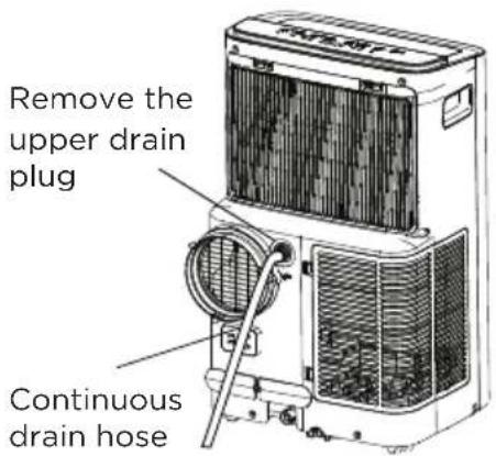
text_image
Remove the upper drain plug Continuous drain hoseNOTICE
Make sure the hose is secure so there are no leaks. Direct the hose toward the drain, making sure that there are no kinks that will stop the water flowing. Place the end of the hose into the drain and make sure the end of the hose is down to let the water flow smoothly. When the continuous drain hose is not used, ensure that the corresponding drain plug and knob are installed firmly to prevent leakage.
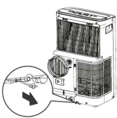
natural_image
Illustration of a portable air conditioner unit with a magnified inset showing internal components (no text or symbols)Operating Instructions
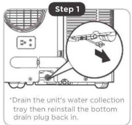
When the water level of the bottom tray reaches a predetermined level, the unit beeps 8 times, the digital display area shows "P1". At this time the air conditioning/dehumidification process will immediately stop. However, the fan motor will continue to operate (this is normal).
Carefully move the unit to a drain location, remove the bottom drain plug and let the water drain away. Reinstall the bottom drain plug and restart the machine until the "P1" symbol disappears. If the error repeats, call for service.
NOTICE
Be sure to reinstall the bottom drain plug firmly to prevent leakage before using the unit.
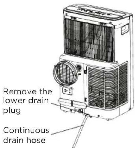
text_image
Remove the lower drain plug Continuous drain hoseCLEANING & MAINTENANCE
Air Filter & Cabinet Cleaning
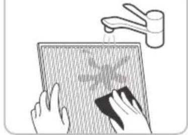
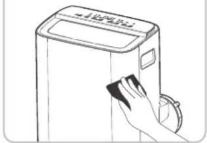
Clean the unit using a damp, lint-free cloth and mild detergent. Dry the unit with a dry, lint-free cloth.
• Take the filter out along the arrow direction.
- Wash the air filter by immersing it gently in warm water (about 40^ C/104°F) with a neutral detergent.
- Rinse the filter and dry it in a shady place.
• Install the air filter after cleaning.

CAUTION
DO NOT operate the unit without filter because dirt and lint will clog it and reduce performance.
natural_image
Technical line drawing of a mechanical device with internal components and directional arrows indicating flow or movement (no text or symbols present)Remove the air filter
Maintenance Tips
- Be sure to clean the air filter every 2 weeks for optimal performance.
- The water collection tray should be drained immediately after P1 error occurs, and before storage to prevent mold.
- In households with animals, you will have to periodically wipe down the grill to prevent blocked airflow due to animal hair.

CAUTION
• Always unplug the unit before cleaning or servicing.
• DO NOT use flammable liquids or chemicals to clean the unit.
- DO NOT wash the unit under running water. Doing so causes electrical danger.
- DO NOT operate the machine if the power supply was damaged during cleaning. A damaged power cord must be replaced with a new cord from the manufacturer.
Store The Unit When Not In Use
text_image
Step 1 *Drain the unit's water collection tray then reinstall the bottom drain plug back in.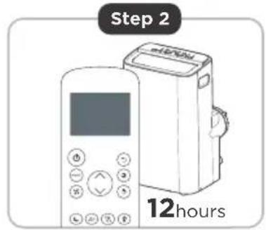
text_image
Step 2 12hours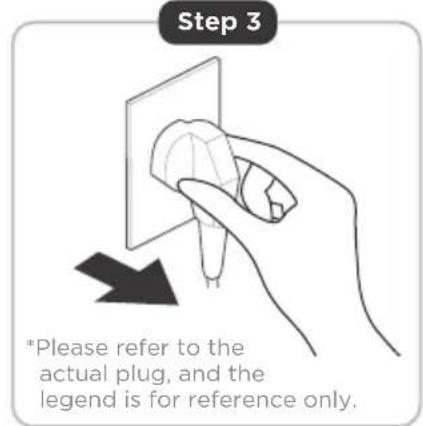
text_image
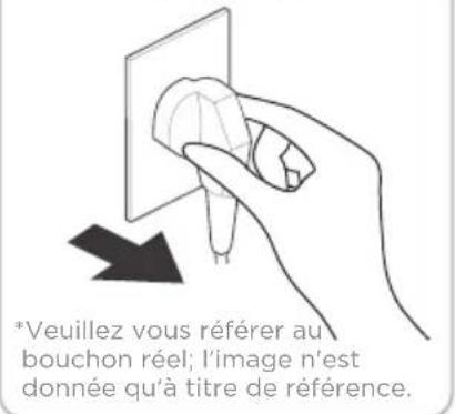
Step 3 *Please refer to the actual plug, and the legend is for reference only.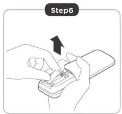
text_image
Step6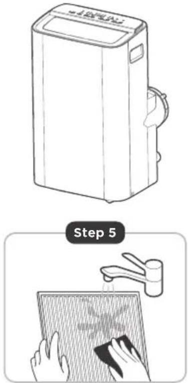
text_image
Step 5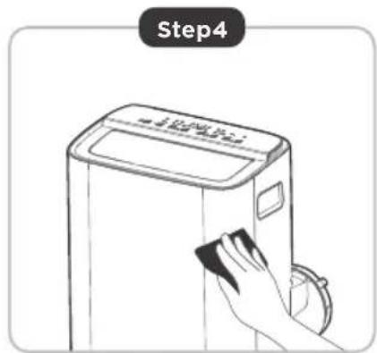
text_image
Step4Step 1: Drain the unit's water collection tray according to the instructions in the following section.
Step 2: Run the appliance on FAN mode for 12 hours in a warm room to dry it and prevent mold.
Step 3: Turn off the appliance and unplug it.
Step 4: Clean the machine.
Step 5: Clean the air filter according to the instructions in the previous section. Reinstall the clean, dry filter before storing.
Step 6: Remove the batteries from the remote control.
NOTICE
- Be sure to store the unit in a cool, dark place. Exposure to direct sunshine or extreme heat can shorten the lifespan of the unit.
- The cabinet and front may be dusted with an oil-free cloth or washed with a cloth dampened in a solution of warm water and mild liquid dishwashing detergent. Rinse thoroughly and wipe dry. Never use harsh cleansers, wax or polish on the cabinet front. Be sure to wring excess water from the cloth before wiping around the controls. Excess water in or around the controls may cause damage to the unit.
TROUBLESHOOTING TIPS
Common Issues
The following problems are not a malfunction and in most situations will not require repairs.
Problem Solution
| Unit does not turn on when pressing ON/OFF button | P1 Protection Code. The water collection tray is full. | Turn off the unit, drain the water from the Water Collection Tray and restart the unit. |
| In COOL mode: room temperature is lower than the set temperature. | Check the set temperature. | |
| Unit does not cool well | The air filter is blocked with dust or animal hair. | Turn off the unit and clean the filter according to instructions. |
| Exhaust hose is not connected or is blocked. | Turn off the unit, disconnect the hose, check for blockage an reconnect the hose. | |
| The unit is low on refrigerant. | Call a service technician to inspect the unit and top off refrigerant. | |
| Temperature setting is too high. | Decrease the set temperature. | |
| The windows and doors in the room are open. | Make sure all windows and doors are closed. | |
| The room area is too large. | Double-check the cooling area. | |
| There are heat sources inside the room. | Remove the heat sources if possible. | |
| The unit is noisy and vibrates too much | The ground is not level. | Place the unit on a flat, level surface. |
| The air filter is blocked with dust or animal hair. | Turn off the unit and clean the filter according to instructions. | |
| The unit makes a gurgling sound | This sound is caused by the refrigerant flow inside the unit. | This is normal. |
REMOTE CONTROL AND APP INSTRUCTIONS
Remote Control Specifications
| Model | RG57H4(B2)/BGCEF |
| Rated voltage 3.0V (Dry batteries) | R03/LR03x2) |
| Signal receiving range 26 ft. (approx. 8 m) | |
| Environment | -5°C ~ 60°C (23°F ~ 140°F) |
Function Buttons
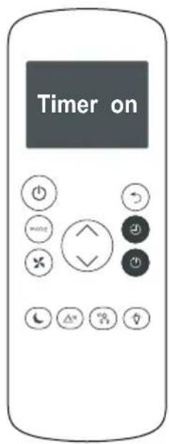
Before you begin using your new air conditioner, make sure to familiarize yourself with its remote control. The following is a brief introduction to the remote control itself. For instructions on how to operate your air conditioner, refer to the Operating Instructions section of this manual.
text_image
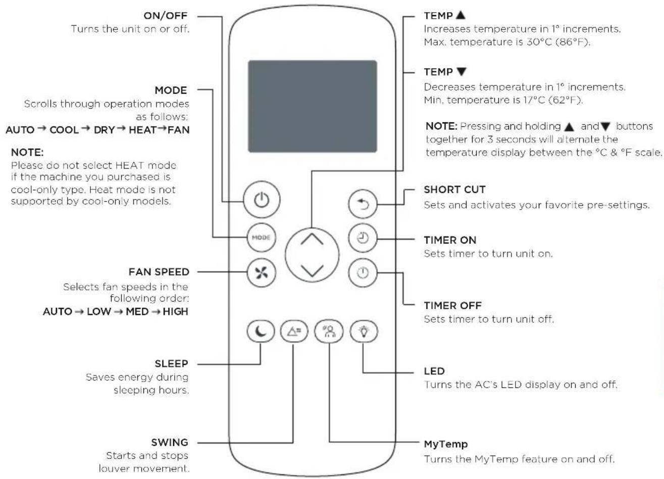
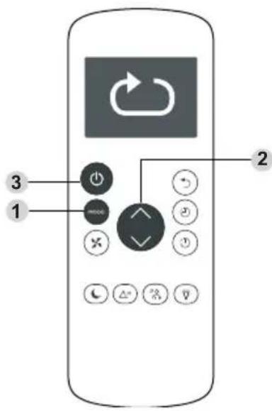
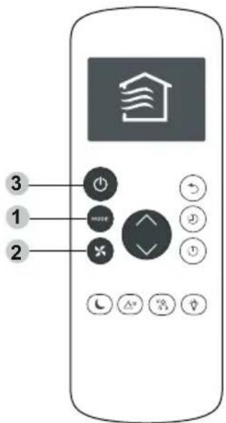
ON/OFF Turns the unit on or off. MODE Scrolls through operation modes as follows: AUTO → COOL → DRY → HEAT → FAN NOTE: Please do not select HEAT mode if the machine you purchased is cool-only type. Heat mode is not supported by cool-only models. FAN SPEED Selects fan speeds in the following order: AUTO → LOW → MED → HIGH SLEEP Saves energy during sleeping hours. SWING Starts and stops louver movement. TEMP ▲ Increases temperature in 1° increments. Max. temperature is 30°C (86°F). TEMP ▼ Decreases temperature in 1° increments. Min. temperature is 17°C (62°F). NOTE: Pressing and holding ▲ and ▼ buttons together for 3 seconds will alternate the temperature display between the °C & °F scale. SHORT CUT Sets and activates your favorite pre-settings. TIMER ON Sets timer to turn unit on. TIMER OFF Sets timer to turn unit off. LED Turns the AC's LED display on and off. MyTemp Turns the MyTemp feature on and off.Handling the Remote Control
NOT SURE WHAT A FUNCTION DOES?
Refer to the Operating Instructions section of this manual for a detailed description of the functions available using the remote.
NOTICE
Button designs on your unit may differ slightly from the example shown.
If the unit does not have a specific function, using that function's button on the remote control will have no effect.
natural_image
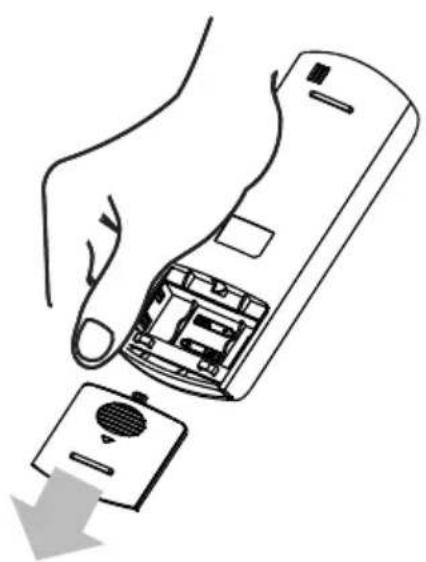
Line drawing of a hand holding a remote control device with a button and a download arrow (no text or symbols)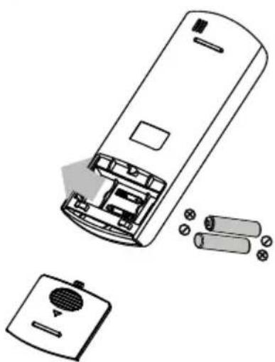
natural_image
Diagram of a remote control casing with battery pack and internal components (no text or symbols)INSERTING AND REPLACING BATTERIES
Your air conditioning unit comes with two AAA batteries. Insert the batteries in the remote control before use.
- Slide the back cover of the remote control downward, exposing the battery compartment.
- Insert the batteries, paying attention to align the (+) and (-) ends of the batteries with the symbols inside the battery compartment.
- Slide the battery cover back into place.
BATTERY NOTES
For optimum product performance:
• Do not mix old and new batteries, or batteries of different types.
- Do not leave batteries in the remote control if you don't plan on using the device for more than 2 months.
BATTERY DISPOSAL
Ensure used batteries are disposed of properly.
TIPS FOR USING REMOTE CONTROL
- The remote control must be used within 26 feet / 8 meters of the unit.
- The unit will beep when it receives a signal from the remote. Curtains, other materials and direct sunlight can interfere with the IR signal receiver.
- In order to properly transmit a command, the ON/OFF indicator must be illuminated on the remote's display. (See the Remote LED Screen Indicators section for more information.)
Remote LED Screen Indicators
Transmission Indicator
Lights up when remote sends signal to unit
MODE display
Displays the current mode, including:
AUTO
- COOL *
- DRY
- HEAT
FAN
ON/OFF display
Appears when the remote is enabled and can send a signal to the unit. If you would like to turn the remote off without affecting the unit, point the remote away from the unit and press the ON/OFF button.
To turn the remote on, point the remote away from the unit and press the ON/OFF button.
The unit will not receive commands from the remote if this indicator is not illuminated.


TIMER ON display
Displays when TIMER ON is set
TIMER OFF display
Displays when TIMER OFF is set

Auto
Timer On Timer Off
Set Temp.


Cool

Dry

Heat


text_image
8.8°F %
Battery display
Low battery detection
SLEEP display
Displays when SLEEP function is activated
MyTemp display
Indicates that the MyTemp function is on
FAN SPEED display
Displays selected FAN SPEED:
HIGH >>>>>
MED >>>>>
LOW >>
This display is blank when set to AUTO speed.
Temperature/Timer display
Displays the set temperature by default, or timer setting when using TIMER ON/OFF functions:
- Temperature range: 17°C-30°C (62°F-86°F)
- Timer setting range: 0-24 hours
This display is blank when operating in FAN mode.
Basic Functions
text_image
Diagram of a mobile phone control panel with labeled buttons and icons, showing function keys and navigation controls.SETTING THE DESIRED TEMPERATURE
The operating temperature range for this unit is 17-30°C (62°F-86°F). You can increase or decrease the set temperature in 1°C or 1°F increments.
Changing the Mode
- To change the operating mode, press the MODE button until the desired mode appears on the remote's display.
- Set the desired temperature.
NOTICE
If the unit does not change when the button is pressed, check that the ON/OFF indicator is illuminated. If it is not, point the remote at the unit and press the ON/OFF button.
text_image
③ ① ②Changing the Fan Speed
To change the fan speed, press the FAN button until the desired fan speed appears on the remote's display.
NOTICE
If the unit does not change when the button is pressed, check that the ON/OFF indicator is illuminated. If it is not, point the remote at the unit and press the ON/OFF button.
Timer Functions
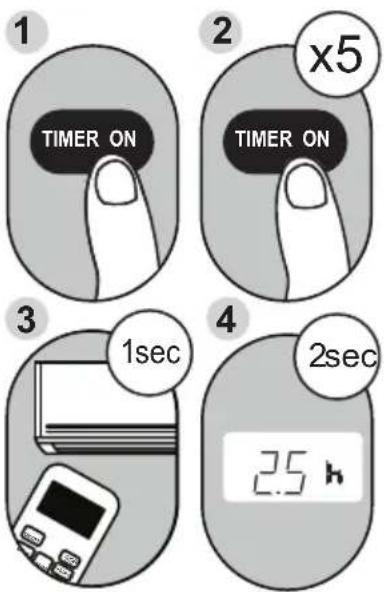
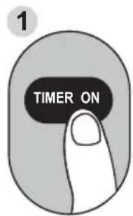
Example: Setting unit to turn on after 2.5 hours.
Your air conditioning unit has two timer-related functions:
TIMER ON - sets the amount of time after which the unit will automatically turn on.
TIMER OFF - sets the amount of time after which the unit will automatically turn off.
TIMER ON Function
The TIMER ON function allows you to set a period of time after which the unit will automatically turn on, such as when you come home from work.
- Press the TIMER ON button. By default, the last time period that you set and an "h" (indicating hours) will appear on the display.
NOTICE
This number indicates the amount of time after the current time after which you want the unit to turn on.
For example, if you set TIMER ON for 2 hours, "2.0h" will appear on the screen, and the unit will turn on after 2 hours.
- Press the TIMER ON button repeatedly to set the time that you want the unit to turn on.
- Wait 2 seconds, then the TIMER ON function will be activated. The digital display on your remote control will then return to the temperature display.
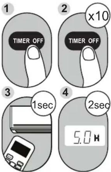
Example: Setting unit to turn off after 5 hours.
TIMER OFF Function
The TIMER OFF function allows you to set a period of time after which the unit will automatically turn off, such as when you wake up.
- Press the TIMER OFF button. By default, the last time period that you set and an "h" (indicating hours) will appear on the display.
NOTICE
This number indicates the amount of time after the current time after which you want the unit to turn off.
For example, if you set TIMER OFF for 2 hours, "2.0h" will appear on the screen, and the unit will turn off after 2 hours.
- Press the TIMER OFF button repeatedly to set the time that you want the unit to turn off.
Timer Functions (cont.)
text_image
Timer onContinue
to press
TIMER ON
or
TIMER OFF
until desired
time is
reached.
- Wait 2 seconds, then the TIMER OFF function will be activated. The digital display on your remote control will then return to the temperature display.
NOTICE
When setting the TIMER ON or TIMER OFF functions, up to 10 hours, the time will increase in 30 minute increments with each press. After 10 hours and up to 24, it will increase in 1 hour increments. The timer will revert to zero after 24 hours.
You can turn off either function by setting the timer to "0.0h".
text_image
1 TIMER ON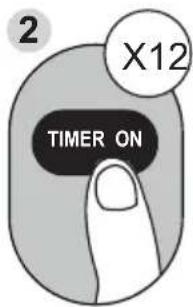
text_image
2 X12 TIMER ON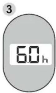
text_image
3 6.0 h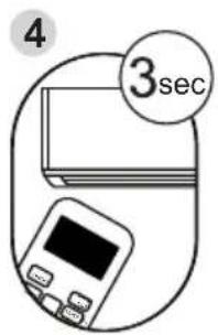
text_image
4 3sec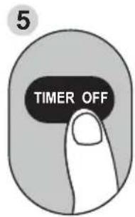
text_image
5 TIMER OFF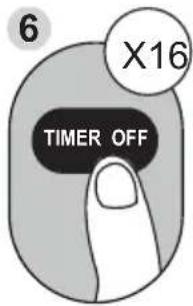
text_image
6 X16 TIMER OFF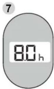
text_image
7 80 h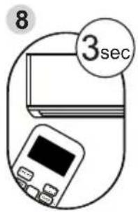
text_image
8 3secSetting Both TIMER ON And TIMER OFF At The Same Time
Keep in mind that the time periods you set for both functions refer to hours after the current time. For example, say that the current time is 1:00 PM, and you want the unit to turn on automatically at 7:00 PM and want it to operate for 2 hours, then automatically turn off at 9:00 PM. Do the following (side figure):
Example: Setting the unit to turn on after 6 hours, operate for 2 hours, then turn off (see the figure below).
Your remote display
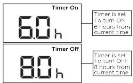
text_image
Timer On 6.0 h Timer is set To turn ON 6 hours from current time Timer Off 8.0 h Timer is set To turn OFF 8 hours from current time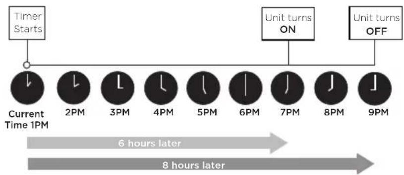
flowchart
graph LR
    A["Timer Starts"] --> B["Current Time 1PM"]
    B --> C["2PM"]
    C --> D["3PM"]
    D --> E["4PM"]
    E --> F["5PM"]
    F --> G["6PM"]
    G --> H["7PM"]
    H --> I["8PM"]
    I --> J["9PM"]
    J --> K["Unit turns OFF"]
    style A fill:#f9f,stroke:#333
    style K fill:#f9f,stroke:#333
    note right of B: 6 hours later
    note left of D: 8 hours later
How to Use the Advanced Functions
SLEEP Function
The SLEEP function is used to decrease energy use while you sleep (and don't need the same temperature settings to stay comfortable).
Note: The SLEEP function is not available in FAN or DRY mode.
SWING Function
Used to stop or start louver movement and set the desired up/down air flow direction. The louver angle changes in 6 degree increments with each press (not all models). By pressing for more than 2 seconds, the louver auto swing feature is activated.
MyTemp Function
The MyTemp function enables the remote control to measure the temperature at its current location.
When using AUTO, COOL, or HEAT functions, measuring ambient temperature from the remote control (instead of from the indoor unit itself) will enable the air conditioner to optimize the temperature around you and ensure maximum comfort.
- Press the button to activate function. The remote control will send temperature signal to the unit every three minutes.
- Press the button again to turn off this function.
SHORTCUT Function
- Used to restore the current settings or resume previous settings.
- Push this button when remote controller is on, the system will automatically revert back to the previous settings including operating mode, setting temperature, fan speed level and sleep feature (if activated).
- By pressing for more than 2 seconds, the system will automatically store the current operation settings including operating mode, setting temperature, fan speed level and sleep feature (if activated).
NOTICE
This device complies with part 15 of the FCC Rules. Operation is subject to the following two conditions: (1) This device may not cause harmful interference, and (2) this device must accept any interference received, including interference that may cause undesired operation.
Note: This equipment has been tested and found to comply with the limits for a Class B digital device, pursuant to part 15 of the FCC Rules. These limits are designed to provide reasonable protection against harmful interference in a residential installation. This equipment generates, uses and can radiate radio frequency energy and, if not installed and used in accordance with the instructions, may cause harmful interference to radio communications. However, there is no guarantee that interference will not occur in a particular installation.
If this equipment does cause harmful interference to radio or television reception, which can be determined by turning the equipment off and on, the user is encouraged to try to correct the interference by one or more of the following measures:
• Reorient or relocate the receiving antenna.
- Increase the separation between the equipment and receiver.
- Connect the equipment into an outlet on a circuit different from that to which the receiver is connected.
- Consult the dealer or an experienced radio/TV technician for help.
DECLARATION OF CONFORMITY
We hereby declare that this AC is in compliance with the essential requirements and other relevant provisions of Directive 1999/5/EC.
SPECIFICATION OF WIRELESS MODULE
| Model: US-SK105 | Dimensions: 41 x 24 x 5 (mm) |
| Antenna Type: Printed PCB Antenna | Operation Temperature: 0°C ~ 45°C / 32°F ~ 113°F |
| Frequency Band: 2400-2483.5MHz | Operation Humidity: 10% ~ 85% |
| Maximum Transmitted Power: <20 dBm Max | Power Input: DC 5V/300 mA |
PRECAUTIONS
- Supports operating systems: iOS 7+ or Android 4+.
-
In the event of a OS update, there may be a delay between the update of the OS and a related software update during which your OS may or may not be supported until a new version is released. Your specific mobile phone or problems in your network may prevent the system from working and Toshiba will not be responsible for any problems that could be caused by incompatibility or network issues.
-
This Smart AC only supports WPA-PSK/WPA2-PSK (recommended) encryption.
Please check the Toshiba Lifestyle website, www.toshiba-lifestyle.com, for updated information.
-
To ensure proper scanning of the QR code, your smart phone must have at least a 5-megapixel camera.
-
Due to unstable network connectivity, requests may time out. If this happens, re-run the network configuration.
-
Due to unstable network connectivity, commands may time out. If this happens, the smartphone app and the actual product may display conflicting information. The information displayed on the actual product is always the most accurate available. Refresh the app to re-sync.
NOTICE
Toshiba will not be responsible for any problems that could be caused by incompatibility or network issues, your wireless router and mobile phone.
SYSTEM OVERVIEW
Devices Required To Use The Smart AC:
- Smart Phone with compatible iOS or Android system.
- Wireless Router (a 2.4GHz network is required to connect).
- Smart Air Conditioner.
DOWNLOAD AND INSTALL THE APP
Android QR code

text_image
QR code image containing encoded data, no visible human-readable text
Apple QR code

text_image
QR code image containing encoded data, no visible human-readable text
Scan to download app.
- You can also go to Google Play or App Store and search for Toshiba NA AC. For more information, please refer to Toshiba Lifestyle website: www.toshiba-lifestyle.com
NOTICE
All the images in this manual are for reference only, your product and app may look slightly different. The actual product and app instructions have to be considered.
CREATE YOUR ACCOUNT
- Make sure your smartphone is connected to your wireless router and your wireless router has a working 2.4GHz internet connection.
• It is recommended to activate your account immediately to be able to recover your password by email.

text_image
AT&T LTE 8:30 PM ¥29% TOSHIBA AC NA Mail Password Login Forgot password? Sign up6.1 Press "Sign Up".

text_image
Enter your Email address Password Confirm Password I have read and agree to the terms and privacy6.2 Enter your email address and password.

text_image
Sign up Enter your Email address Password Confirm Password Register I have read and agree to the terms and privacy.6.3 Press "Register".

text_image
AT&T 10:00 AM Forgot password Enter your email address. Reset Password6.4 If you forget your password, press "Forgot password?" on the main menu and enter your email address. Then press "Reset Password".
NOTICE
• Make sure your smartphone is able to connect to the wireless network which will be used.
• Make sure also that the device is not connecting to other networks in range.
NOTICE
Declaration of Conformity
CONTAINS FCC ID: 2ADQOMDNA21
CONTAINS IC : 12575A-MDNA21
In Canada, it should comply with CAN ICES-3(B)/NMB-3(B)
This device complies with Part 15 of the FCC Rules and it contains licence-exempt transmitter(s)/receiver(s) that comply with Innovation, Science and Economic Development Canada's licence-exempt RSS(s). Operation is subject to the following two conditions:
(1) This device may not cause interference; and
(2) This device must accept any interference, including interference that may cause undesired operation of the device.
Only operate the device in accordance with the instructions supplied. Changes or modifications to this unit not expressly approved by the party responsible for compliance could void the user's authority to operate the equipment. This device complies with FCC radiation exposure limits set forth for an uncontrolled environment. In order to avoid the possibility of exceeding the FCC radio frequency exposure limits, human proximity to the antenna shall not be less than 20cm (8 inches) during normal operation.
Note: This equipment has been tested and found to comply with the limits for a Class B digital device, pursuant to part 15 of the FCC Rules. These limits are designed to provide reasonable protection against harmful interference in a residential installation. This equipment generates, uses and can radiate radio frequency energy and, if not installed and used in accordance with the instructions, may cause harmful interference to radio communications. However, there is no guarantee that interference will not occur in a particular installation. If this equipment does cause harmful interference to radio or television reception, which can be determined by turning the equipment off and on, the user is encouraged to try to correct the interference by one or more of the following measures:
• Reorient or relocate the receiving antenna.
- Increase the separation between the equipment and receiver.
- Connect the equipment into an outlet on a circuit different from that to which the receiver is connected.
- Consult the dealer or an experienced radio/TV technician for help.
Company will not be liable for any issues and problems caused by Internet, Wireless Router and Smart Devices. Please contact the original provider to get further help.
Supplier's Declaration of Conformity
47 CFR § 2.1077 Compliance Information
Responsible Party U.S. Contact Information
Midea America Corporation
300 Kimball Dr
Parsippany NJ
07054
Telephone number or internet contact information: Midea.com/us
FCC Compliance Statement (products subject to Part 15)
This device complies with Part 15 of the FCC Rules. Operation is subject to the following two conditions: (1) This device may not cause harmful interference, and (2) this device must accept any interference received, including interference that may cause undesired operation.

WARNING: Chemical Burn Hazard. Keep batteries away from children.
This product contains a lithium button/coin cell battery. If a new or used lithium button/coin cell battery is swallowed or enters the body, it can cause severe internal burns and can lead to death in as little as 2 hours. Always completely secure the battery compartment. If the battery compartment does not close securely, stop using the product, remove the batteries, and keep it away from children. If you think batteries might have been swallowed or placed inside any part of the body, seek immediate medical attention.
TOSHIBA
TOSHIBA
natural_image
Line drawing of a portable air purifier with control panel and side arm (no text or symbols)GUIDE D'UTILISATION
Operation of Current Device
text_image
Plug in & press RESET RESET TESTThe power supply cord contains a measurement current device that senses damage to the power cord.
Test your power supply cord as follows:
- Plug in the air conditioner.
- The power supply cord will have TWO buttons on the plug head. Press the TEST button. You will notice a click as the RESET button pops out.
- Press the RESET Button. You will notice a click as the button engages.
- The power supply cord is now supplying electricity to the unit. (On some products this is also indicated by a light on the plug head.)
NOTICE

text_image
Grounding type wall receptacle Do not, under any circumstances, cut, remove or bypass the grounding prong. Power supply cord with 3-prong grounding plug and current detection device.The power supply cord with this air conditioner contains a current detection device designed to reduce the risk of fire.
In the event that the power supply cord is damaged, it can not be repaired. It must be replaced with a cord from the manufacturer.
NOTICE
- Do not use this device to turn the unit on or off.
• Always make sure the RESET button is pushed in for correct operation. - The power supply must be replaced if it fails to reset when either the TEST button is pushed, or it can not be reset. Please contact Customer Service.

AVERTISSEMENT
text_image
Technical diagram of a refrigerator with numbered labels pointing to different parts of the cabinet.text_image
Technical diagram of a refrigerator with numbered components and labeled partsnatural_image
Simple diagram with four rectangular boxes, one containing a rounded rectangle and three empty (no text or symbols)natural_image
Simple line drawing of a window frame with three panes and a shaded vertical panel on the right (no text or symbols)
natural_image
Simple line drawing of a cabinet or shelf with two horizontal panels and a gray bottom section (no text or symbols)natural_image
Diagram of a bent pipe with coiled insulation, no text or symbols presentnatural_image
Diagram showing a mechanical assembly with cross-sectional views and an arrow indicating transformation (no text or symbols present)natural_image
Line drawing of an air conditioner unit with a fan emitting vapor (no text or symbols)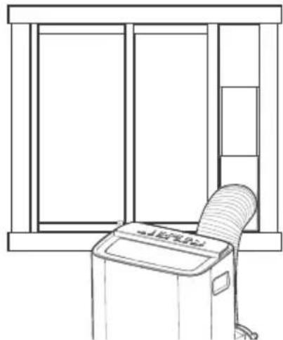
natural_image
Line drawing of a window with a computer monitor and fan (no text or symbols)natural_image
Technical illustration of a portable air conditioner unit with a magnified inset showing internal components (no text or symbols)natural_image
Technical line drawing of a mechanical device with internal components and directional arrows indicating flow or movement (no text or symbols present)natural_image
Line drawing of a portable air conditioner unit with lid and side panel (no text or symbols)Étape 3
natural_image
Illustration of hands using a handheld device to adjust or install a component, with an upward arrow indicating action (no text or symbols present)Étape 5
natural_image
Illustration of hands cleaning a textured surface with a faucet above (no text or symbols)Étape 4
natural_image
Line drawing of a hand cleaning a kitchen appliance with a cloth (no text or symbols)text_image
Diagram of a mobile phone control panel with labeled buttons and function iconsTEMP
natural_image
Line drawing of a hand holding a remote control device with an open rear panel and a downward arrow indicating action (no text or symbols)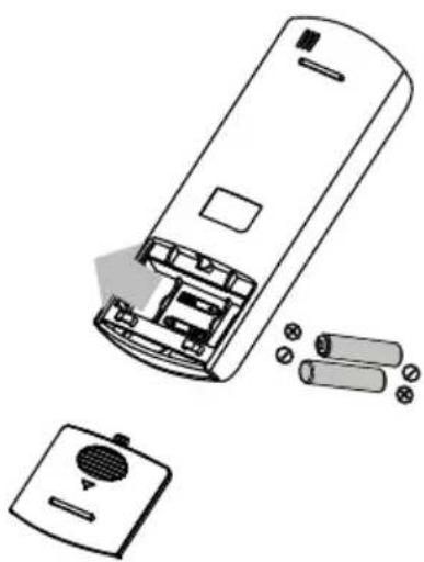
natural_image
Line drawing of a remote control casing with internal components and battery pack (no text or symbols)INSERTION ET REMPLACEMENT DES PILES
text_image
Diagram of a remote control device with labeled buttons and function iconsRÉGLAGE DE LA TEMPÉRATURE SOUHAITÉE
DÉCLARATION DE CONFORMITÉ
text_image
QR code image containing encoded data, no visible human-readable text

text_image
QR code image containing encoded data, no visible human-readable text
text_image
AT&T LTE 9:30 PM ¥29% TOSHIBA AC NA Mail Password Login Forgot password? Sign up
text_image
Sign up Enter your Email address Password Confirm Password file size I have read and agree to the terms and privacytext_image
Sign up Enter your Email address Password Confirm Password Register I have need and agree to the terms and privacy.