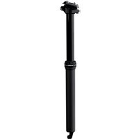
LEV Integra - Bike accessory Kind Shock - Free user manual and instructions
Find the device manual for free LEV Integra Kind Shock in PDF.


| Product Type | Telescopic Seatpost |
| Brand | Kind Shock |
| Model | LEV Integra (and LEV-Ci, LEV-Si, e30-i, Crux-i, eTen-i) |
| Compatible Diameters (seat tube) | 27.2 mm, 30.9 mm, 31.6 mm, 34.9 mm |
| Body Material | Aluminum (LEV Integra) or Carbon (LEV-Ci) |
| Recommended Return Pressure | 100 to 250 psi (do not exceed 250 psi) |
| Seat Collar Torque (frame) | 6 to 7 N·m |
| Remote Lever Torque (alloy) | 4 to 5 N·m |
| Remote Lever Torque (polycarbonate) | 1 to 3 N·m |
| Seat Bolt Torque | 10 N·m (8 N·m for LEV-Ci), 15 N·m (Crux-i), 22 N·m (eTen-i) |
| Control Type | Handlebar cable lever, internal routing |
| Main Function | Lower and raise the saddle continuously over full travel |
| Intended Use | MTB, road bike, cyclocross (depending on frame compatibility) |
| Warranty | 2 years, original purchaser, non-transferable |
| Periodic Maintenance | Every 6 months minimum, cleaning and lubrication by a qualified technician |
| Safety Precautions | Check before each use, do not disassemble, observe torque specifications |
| Frame Compatibility | Requires appropriate seat tube diameter and internal cable routing |
| Tools Required for Installation | Allen keys 3 mm, 4 mm, 5 mm, 6 mm, torque wrench, cable cutter |
| Return Speed Adjustment | Via Schrader valve under top cap, high-pressure pump recommended |
| Spare Parts | Available from KS after-sales service (cable ends, housings, etc.) |
Frequently Asked Questions - LEV Integra Kind Shock
User questions about LEV Integra Kind Shock
0 question about this device. Answer the ones you know or ask your own.
Ask a new question about this device
Download the instructions for your Bike accessory in PDF format for free! Find your manual LEV Integra - Kind Shock and take your electronic device back in hand. On this page are published all the documents necessary for the use of your device. LEV Integra by Kind Shock.
USER MANUAL LEV Integra Kind Shock
This user manual covers the following models: LEV-Ci, LEV Integra, LEV-Si, e30-i, Crux-i, eTen-i
K5
LEV CI, LEV INTEGRA, CRUX-I and eTEN-I USER MANUAL
| English | 1 |
| German | 22 |
| French | 43 |
| Italian | 64 |
| Spanish | 85 |
| Chinese | 106 |
| Japanese | 127 |
Copyright © 2017 Kind Shock Hi-Tech Co. Ltd.
All Rights Reserved
K5
HEIGHT ADJUSTABLE SEATPOST USER MANUAL
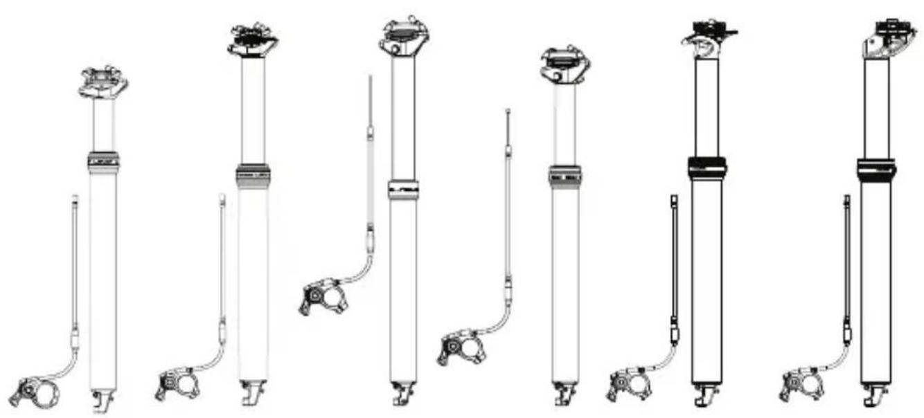
This user manual covers the following models: LEV-Ci, LEV Integra, LEV-Si, e30-i, Crux-i, eTen-i
PLEASE READ THIS FIRST
Thank you for purchasing a new KS Height Adjustable Seatpost. Your new seatpost is warranted for a period of two years from the date of purchase. The warranty is expressly limited to the repair or replacement of the defective part and is the sole remedy of the warranty. The warranty applies only to the original owner and is not transferrable. Proof of purchase is required to validate warranty eligibility. The warranty does not cover normal wear and tear, routine maintenance, improper installation or improper use of the seatpost. Modification of the seatpost in any manor shall void the warranty. Kind Shock Hi-Tech Co. Ltd. shall not be responsible for incidental or individual costs incurred by the warranty service provider that are not covered by this warranty. The user assumes the risk of any personal injury or property damage, including damage to the seatpost, and any other losses, if the seatpost is modified or improperly used at any time. This warranty gives the consumer specific legal rights and those rights vary from state to state. This warranty does not affect the statutory rights of the consumer.
ATTENTION
This is a high performance product. It will give you reliable service if it is installed properly and regularly maintained by an authorized KS Service Center. Please read through these instructions fully and follow them careful before you install your new seatpost.
WARNING
KS Height Adjustable Seatposts must be regularly maintained by an a qualified service technician. If you need assistance locating a qualified service technician, more information can be found at http://www.kssuspension.com. Service center locations can be found at www.kssuspension.com. Do not disassemble your seatpost. Disassembly could cause damage and severe personally injury as some of the contents are under pressure. Failure to follow these warnings and instructions will immediately void your warranty.
BEFORE YOU INSTALL THE SEATPOST
Please be sure your new KS seatpost is designed to fit in your frame. All LEV Integra models are designed to fit either 27.2mm, 30.9mm, 31.6mm or 34.9mm seat tube inner diameters in frames originally designed for internal cable routing. Improper fit may cause slippage, faulty performance, injury and may result in void of warranty.

KS Suspension DOES NOT recommend modification or alteration of your frame in any way. Doing so may void your frame or bicycle's warranty and may result in frame failure which could lead to injury or death.

Make sure your frame is clean and free of debris, grease and the inside of your seat tube is smooth and free of any object that may score the seatpost.

Apply grease to all seatpost bolt threads.

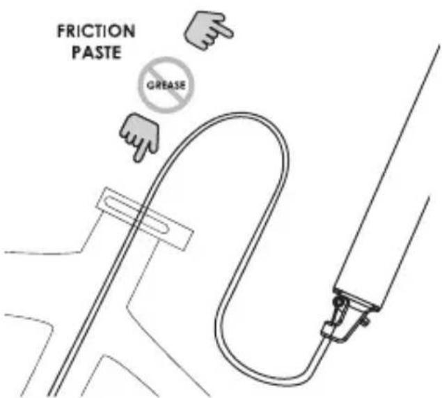
Apply a friction or anti-seize compound to the inside of the seat tube and inserted surface of the seatpost. Do not use grease.

LEV-Ci: This seatpost uses a carbon fiber composite mast. Always install in a clean dry frame and always use fiber prep or suitable compound.
Always use the torque wrench when tightening the seatpost binder bolt. DO NOT EXCEED 5n-m.
SEATPOST INSTALLATION
SEATPOST ORIENTATION
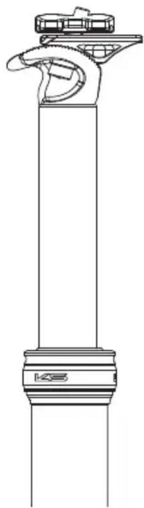
Since Integra models remote cable is internally routed and in-line with the seatpost, there is only one position for saddle orientation:

SEATPOST INSTALLATION
MINIMUM INSERTION DISTANCE
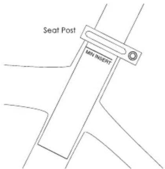
All seat post models must be inserted into the bicycle's seat tube to cover the minimum insertion line indicated on the seat post.

Insufficient insertion of the seat post into the bicycle frame's seat tube could result in damage to the seat post and/or bicycle and may result in a loss of control of the bicycle which may lead to serious injury or death.
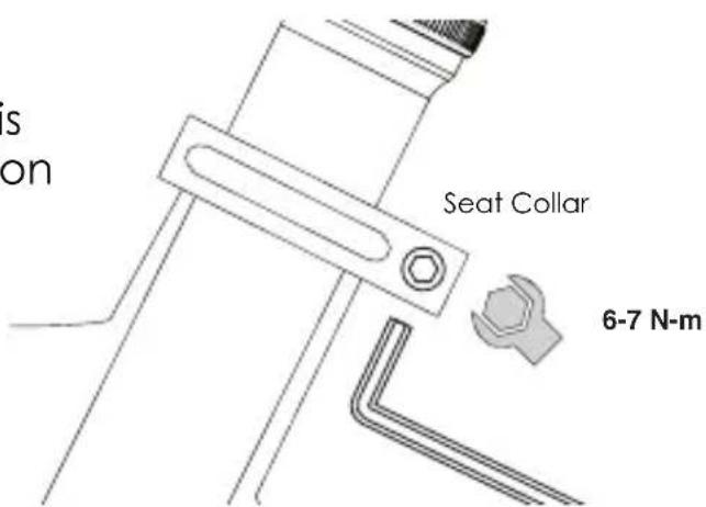
SEAT COLLAR TORQUE
Tighten your frame's seat collar to a maximum torque of 7 N-m. Do not over torque your frame's seat collar as this may inhibit proper function of your seat post.

Do not over torque your frame's seat collar as this may inhibit proper function of your seat post.
INSTALLATION
ATTENTION!
Please read the following instructions carefully and install your LEV Ci, LEV Integra, LEV-Si, e30-i, Crux-i and eTen-i according to the steps detailed below.
Your KS height adjustable seatpost is a precision piece of cycling equipment that requires a specific understanding of bicycle maintenance and assembly to install. If you are not certain you have the appropriate skills or tools to properly install this product, please contact your local bicycle dealer or service provider for assistance.
Detailed installation and service videos for all models can be viewed at http://kssuspension.com/support/tech-info/.
WARNING!
LEV Ci, LEV Integra, LEV-Si, e30-i, Crux-i and eTen-i use internal cable routing and is designed to be compatible with bicycle frames that provide for such cable routing.
DO NOT DRILL OR MODIFY YOUR FRAME IN ANY WAY. Doing so will void the Warranty of LEV Ci, LEV Integra, LEV-Si, e30-i, Crux-i and eTen-i and in most cases void the warranty of your bicycle. Modification of your frame in any way may result in frame failure which could result in injury or death.
If you are unsure if LEV Ci, LEV Integra, LEV-Si, e30-i, Crux-i and eTen-i are compatible with your frame, contact your bicycle frame manufacturer or KS USA at www.kssuspension.com.
INSTALLATION
DETERMINING CABLE AND HOUSING LENGTH
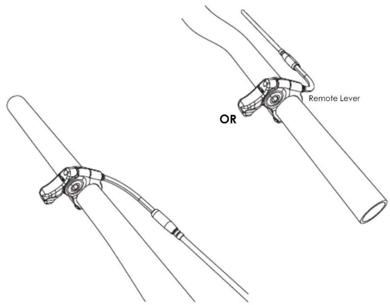
Temporarily install the remote lever in the desired final location. The remote can be installed on either the right or left side of the handlebar.
NOTE: you will use this position to determine cable length but remove and reinstall the lever again in a later step.
Install the supplied elbow noodle with integrated barrel adjuster and insert cable housing into the barrel adjuster.
INSTALLATION
DETERMINING CABLE AND HOUSING LENGTH
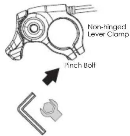
Using a 3mm Hex wrench, loosen the remote lever clamp pinch bolt and remove the bolt. Slide the (non-hinged) lever clamp on your handlebar and position it in the desired location. Tighten to a torque of 1-3 N-m.
NOTE: Aftermarket models of LEV Integra and LEV-Si use the KGSL alloy remote with hinged lever clamp. See below for installation instructions.

WITH ODI LOCK-ON™ COMPATIBLE GRIP (AM ONLY)
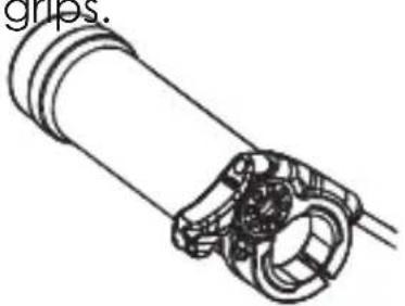
The alloy remote lever clamp can be used to replace the inner lock ring on ODI LOCK-ON TM compatible grips. Remove the inner lock ring on your grip. Replace with the seat post remote lever clamp. Follow the instructions above. NOTE: Polycarbonate remote lever clamp is not hinged and not compatible with ODI LOCK-ON TM compatible grips.
INSTALLATION
DETERMINING CABLE AND HOUSING LENGTH
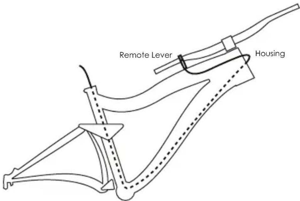
With the housing and noodle in place at the remote lever, route the housing through your bicycle frame per your bicycle frame manufacturers specifications.
To determine the correct length for your housing, pull the housing to remove excess slack with the handlebars turned 90-degree from the forward position. Be sure the housing is long enough to wrap around the head tube as shown to not impede with steering.
NOTE: Do not permanently affix your housing in place. You will need it free to move it in a later step.
INSTALLATION
DETERMINING CABLE AND HOUSING LENGTH
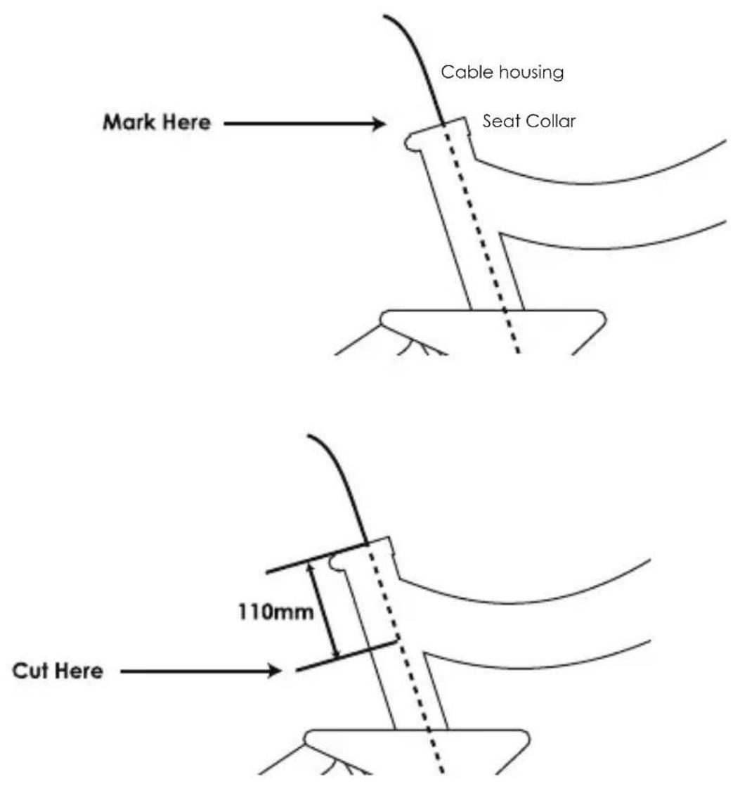
Mark the location on your cable housing at the seat collar as it protrudes from the seat tube. Pull the cable housing out of the seat tube and make another mark 110mm in the direction of the handlebar. This will be your final housing length. Cut the housing to length.
NOTE: This 110mm measurement applies to all travel options.
CABLE INSTALLATION
CONNECTING THE INNER WIRE
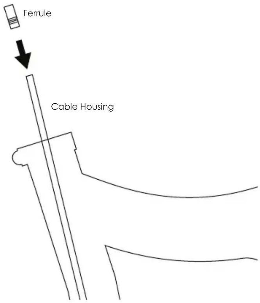
With the housing still routed through your frame, install the ferrule on the end of housing at the seat collar.
CABLE INSTALLATION
CONNECTING THE INNER WIRE
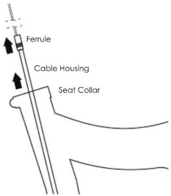
Feed the inner wire through the remote lever, integrated barrel adjuster and cable housing.
![graph TD A["Inner Wire"] --> B["Remote Lever"] B --> C["Ferrule Integrated Barrel Adjuster"] C --> D["Cable Housing"]](/content/2026/04/727226/images/80a0b59c776a13ef8df5d0ac3398ed629cfb495f9bb2784cc011153959bd43be.jpg)
Pull the cable slack out from the seat collar.
CABLE INSTALLATION
Hold the free end of the cable and cable housing to the cable entry point. Mark this length on the cable and cable housing with a marking pen or tape.
Using a pair of bicycle cable cutters, trim the cable housing to this measured length. DO NOT cut the inner wire at this time.
Option 1: Using a standard shifter cable.
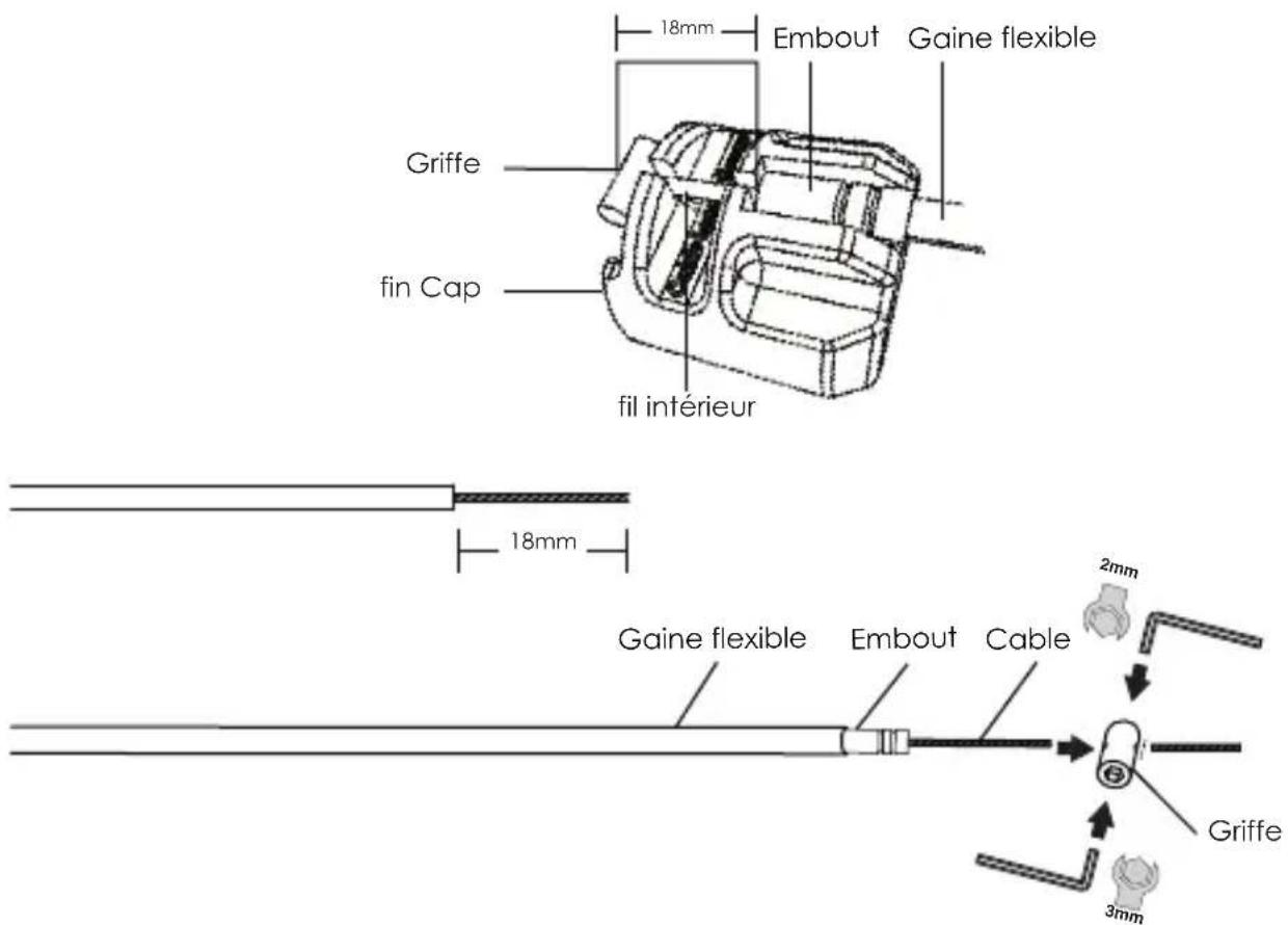
Mark the inner wire to a length 18mm longer than the cable housing or use the gauge molded into the supplied protective cap as shown:
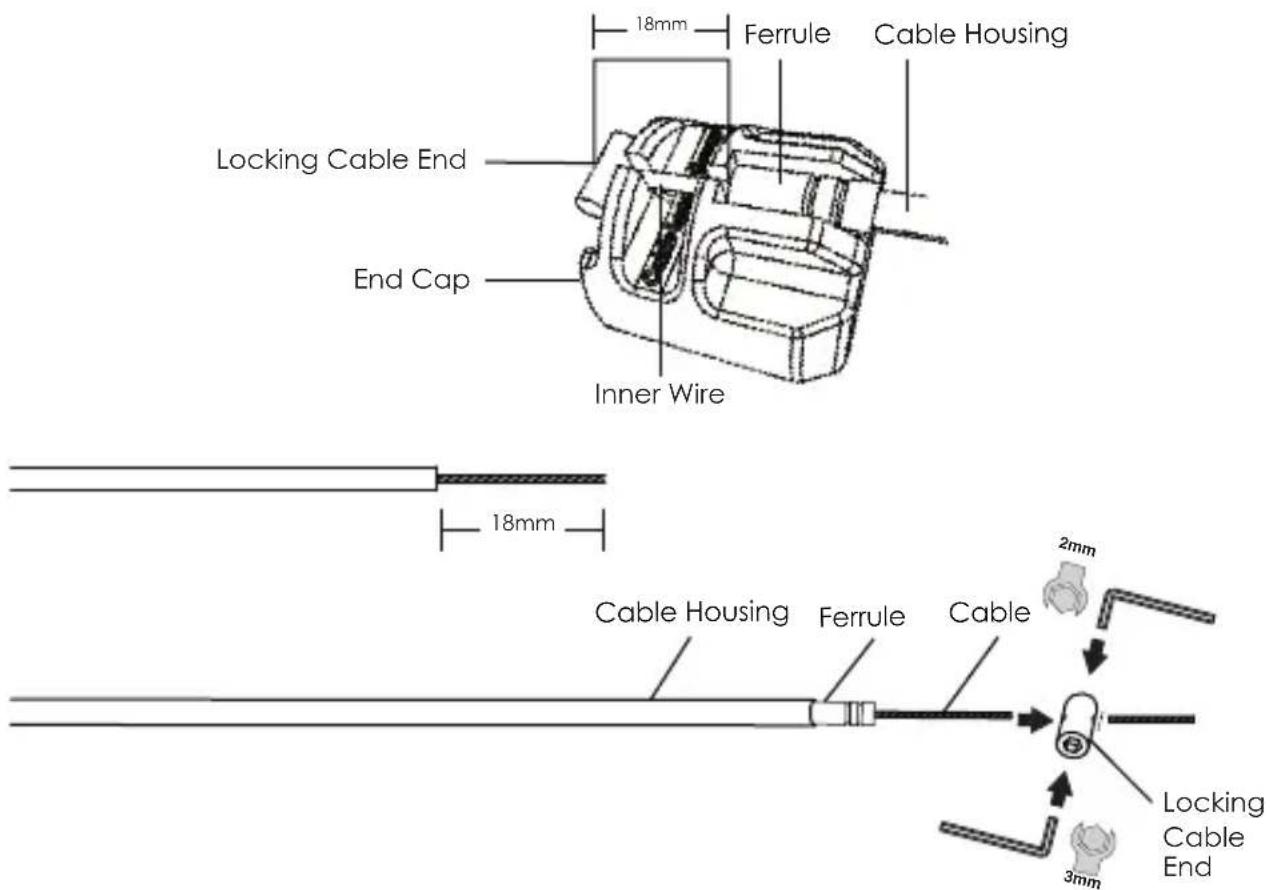
Tighten the locking cable end to the cable using both a 3mm and 2mm Hex wrench. Ensure the inner wire is flush with the locking cable end.
CABLE INSTALLATION
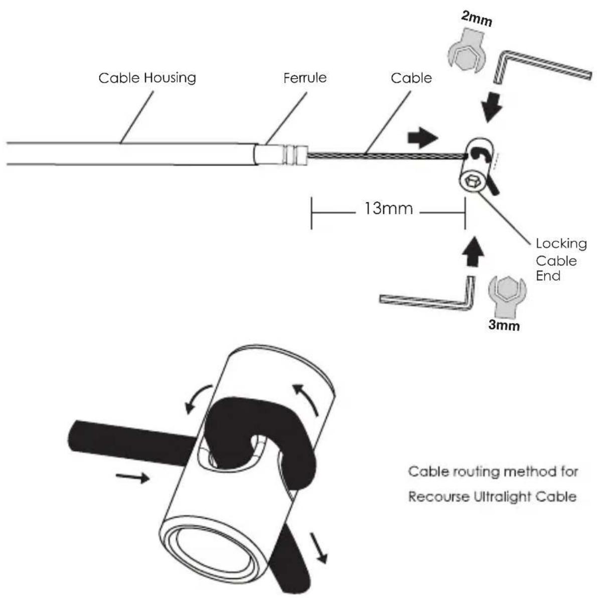
Option 2: Using Recourse Ultralight cable system
Install the LEV-Ci ferrule on the cable housing. Route the Recourse inner wire as shown. Tighten the locking cable end leaving 13mm spacing as shown. Trim the excess inner wire to be flush with the locking cable end.
INSTALLATION
CONNECTING THE INNER WIRE
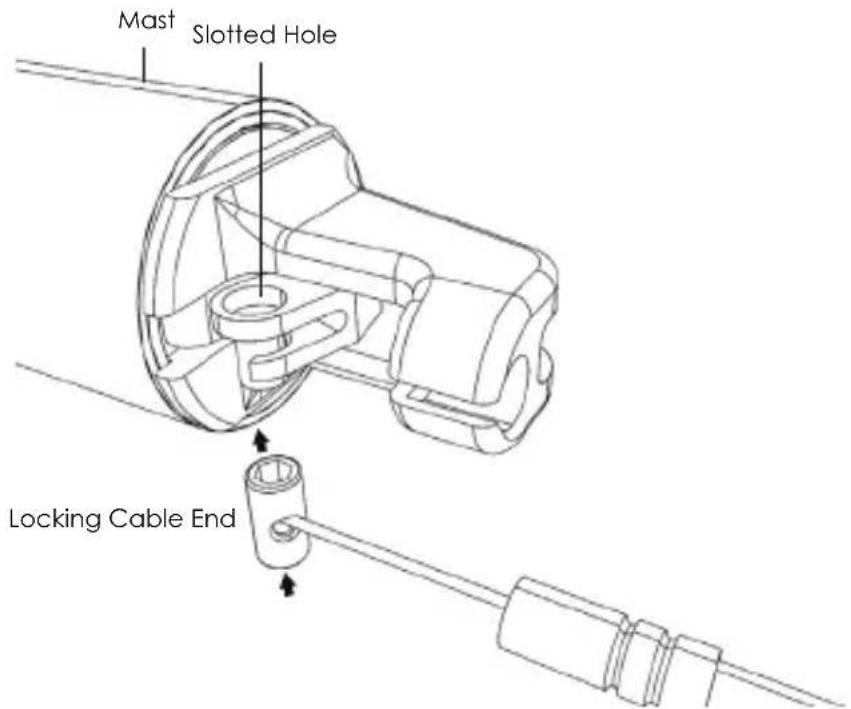
① Insert the Locking Cable End through the slotted hole.
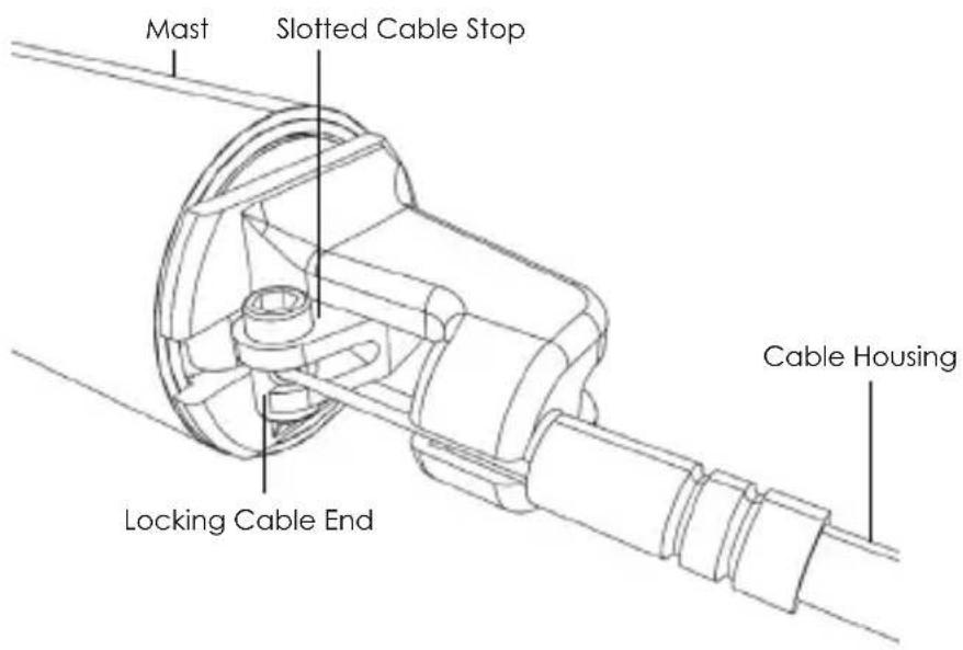
② Insert the housing into the slotted cable stop.
INSTALLATION
INSTALLING ON THE BIKE
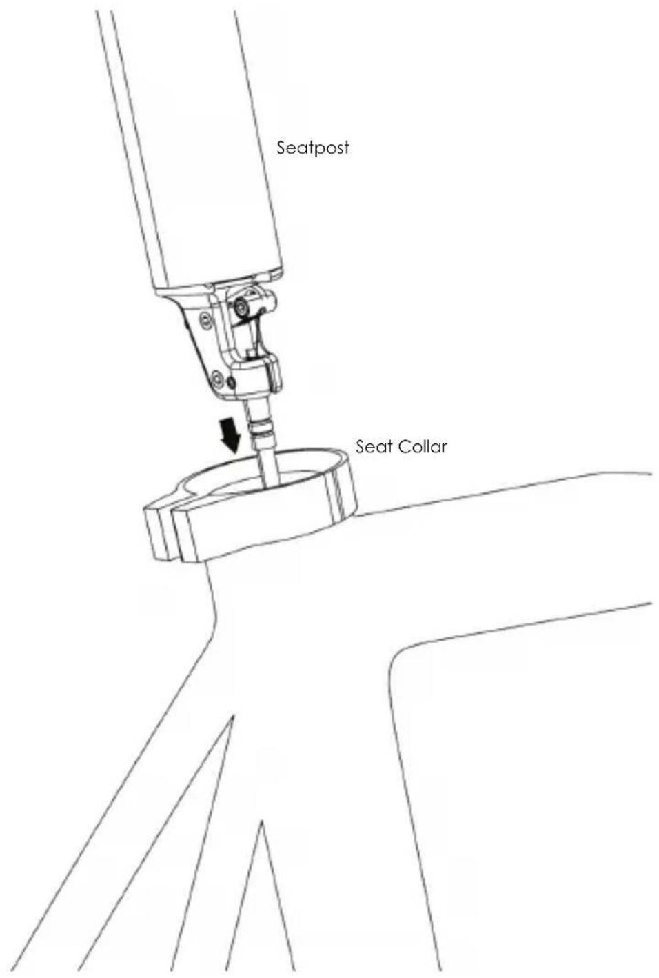
Place your seatpost into your seat collar while taking up the cable slack from where it enters the bicycle frame.
SADDLE INSTALLATION
AFTER SETTING SEATPOST ORIENTATION IN YOUR FRAME
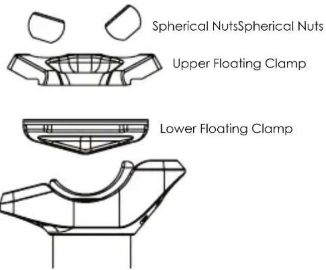
Once you have oriented your seatpost within your seat tube ensuring the saddle is aligned to point forward, you will need to install your saddle. Remove the two saddle head clamp bolts, spherical nuts, upper and lower floating clamp using a 4mm Hex wrench.
Note: The lower clamp body may slide down the stanchion tube at this point.
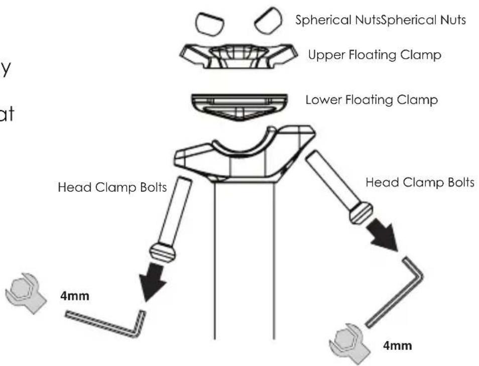
To install the saddle, replace the two saddle head clamp bolts, spherical nuts, upper and lower floating clamp in the order in which they were removed.
Before tightening, place the rails of your saddle between the upper and lower floating clamps so that the rails seat in the channel provided by the lower floating clamp.
Using a 4mm Hex wrench, tighten the two head clamp bolts until the desired saddle angle is achieved. Then tighten both bolts evenly to a maximum torque of 10 N-m (8 N-m LEV-Ci.)
SADDLE INSTALLATION
CRUX-i
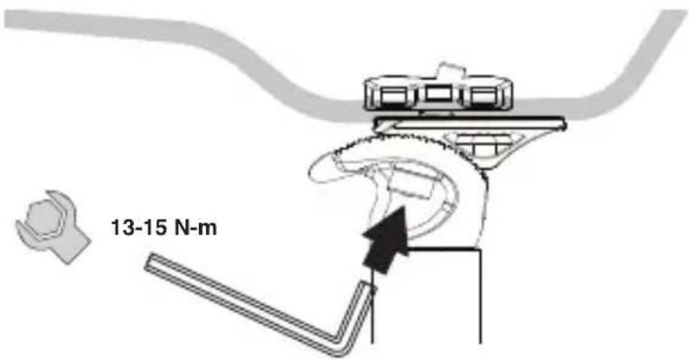
Using a 5mm Hex wrench, loosen the two head clamp bolts until they are nearly free of the upper half of the saddle clamp. Set the fore/aft and angle position of the saddle. Tighten the two head clamp bolts to a maximum torque of 15 N-m.
ETEN-i
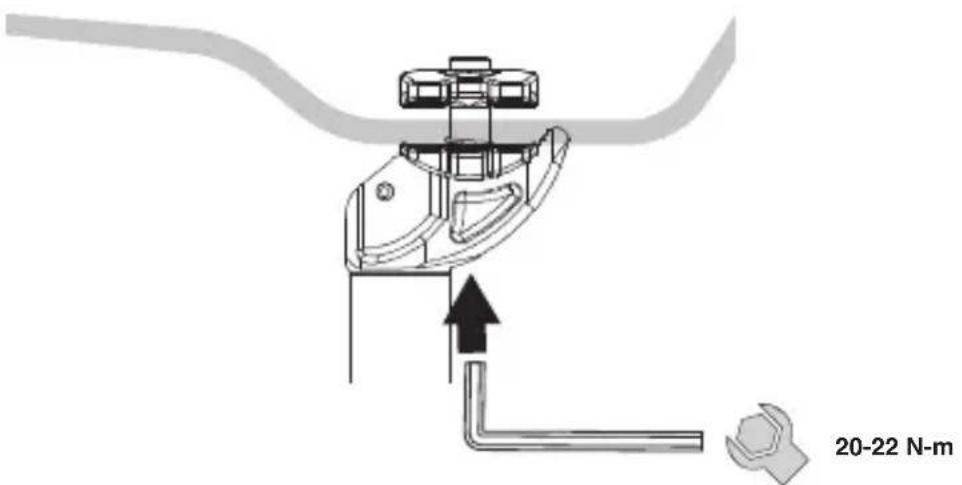
Using a 6mm Hex wrench, loosen the single head clamp bolt until it is nearly free of the upper half of the saddle clamp. Set the fore/aft and angle position of the saddle. Tighten the head clamp bolt to a maximum torque of 22 N-m.
ADJUSTING THE RETURN SPEED
(LEV-Ci, LEV Integra and LEV-Si Only)
NOTE: All LEV Integra models come with suitable pressure for the return spring. Test the return speed of LEV Integra before you make adjustments. If air pressure adjustments still must be made, remove the saddle and saddle clamp parts at top end of the stanchion tube.
Attach a compatible shock pump and adjust to your desired pressure. KS recommends our AIR-8 High Pressure pump for best results.

NOTE: Recommended operating pressures is 100-250psi. Do not exceed 250psi.
USING YOUR SEAT POST
FOR THE FIRST TIME
When using your seat post for the first time, it may be necessary to give the post a firm downward “nudge” to start the initial movement. This is due to the seal’s natural tendency to migrate oil away from the seal surface. This is only necessary prior to the first use or after a long period of non-use. Once the post is cycled through its travel the first time, it will distribute oil on the seal and resume its normal function.
RAISING AND LOWERING THE SADDLE
To lower the saddle, weight the saddle firmly with your hand or sit on the bike while pressing and holding the actuation lever or remote. Release the lever when the desired height is reached.
To raise the saddle, actuate your seat post by pulling the lever or handlebar remote. Unweight the saddle and release the lever when the desired height is reached.
You can raise and lower your saddle to any desired position within the seat post's travel.
SAFETY AND MAINTENACE
BEFORE EACH RIDE
Before each ride, check that the seat post is secure in the frame and that all clamping bolts are tightened to their specified torque values. Make sure that your seat post does not show sign of excessive wear and is not leaking. Check that the seat post functions properly. Make sure that the maximum raised position of the seat post is not too high for the rider to properly maintain control of the bicycle.
PERIODIC MAINTENANCE
Your KS seat post requires periodic service to maintain consistent function. Please see your local dealer to have this service performed.
Routine maintenance should be done at regular intervals. Interval duration will depend on frequency of use and conditions. Post should be cleaned and lubricated at least once every 6 months. Wet or severely dusty conditions will require more frequent maintenance. If a high pressure water is used to wash the bicycle, more frequent maintenance is recommended due to the increased chance of water entering the system. If degradation of performance occurs, perform maintenance as soon as possible.
Videos of service procedures on all models are available at http://kssuspension.com/support/tech-info/.
For more information, please contact your local Service Center. Service Center contact information can be found at http://www.kssuspension.com.
K5
MONTAGE
ETEN-i
http://kssuspension.com/support/tech-info/.
AVERTISSEMENT
INSTALLATION
INSTALLATION
DETERMINATION DE LA LONGUEUR DU CABLE ET DE LA GAINÉ
Mark the inner wire to a length 18mm longer than the cable housing or use the gauge molded into the supplied protective cap as shown:
ETEN-i
Questo manuale é riferito al modello: LEV-Ci, LEV Integra, LEV-Si, e30-i, Crux-i, eTen-i
DA LEGGERE PRIMA DELL'USO
INSTALLAZIONE
DETERMINARE LA LUNGHEZZA DI CAVO E GUAINA
INSTALLAZIONE
DETERMINARE LA LUNGHEZZA DI CAVO E GUAINA
CONNECTING THE INNER WIRE
ETEN-i
Crux-i eTen-iLEV-Ci, LEV Integra,
LEV-Si and e30-i
INSTALACIÓN
PARA DETERMINAR LA LONGITUD DEL CABLE Y LA FUNDA.
INSTALACIÓN
DETERMINAR LA LONGITUD DEL CABLE Y LA FUNDA
ETEN-i
本用戶手冊包括下列型號:LEV-Ci, LEV Integra, LEV-Si, e30-i, Crux-i, eTen-i
保固期限
感謝您購買全新的KS可調高低座管。
座管安装
LEV-Si and e30-i
Crux-i eTen-iLEV-Ci, LEV Integra,
座管安装
安全線位置
拉線安裝
決定內線與外線正確長度:
超輕內線的走線方式
安装
連接內導線
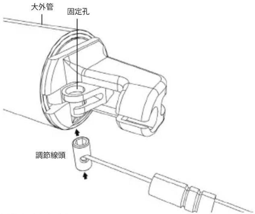
① 將調節線頭穿過固定孔
ETEN-i
LEV-Si and e30-i
Crux-i eTen-iLEV-Ci, LEV Integra,
シートポストの取り付け方法
最低差込ライン
取り付け方法
ケーブルとハウジングの長さ
取り付け方法
ケーブルとハウジングの長さ
ウルトラライトケーブルの取り回し図
インストール
インナーワイヤを接続する
ETEN-i
get down and dirty
Rev.2015.12.a3
KS USA
26741 Portola Pkwy, Suite 1E658
Foothill Ranch, CA 92610
(949) 742-1180
www.kssuspension.com
Copyright 2015 Kind Shock High Tech Co. Ltd. Rev.010517
- K5
- LEV CI, LEV INTEGRA, CRUX-I AND ETEN-I USER MANUAL
- HEIGHT ADJUSTABLE SEATPOST USER MANUAL
- PLEASE READ THIS FIRST
- ATTENTION
- WARNING
- BEFORE YOU INSTALL THE SEATPOST
- SEATPOST INSTALLATION
- SEATPOST ORIENTATION
- MINIMUM INSERTION DISTANCE
- SEAT COLLAR TORQUE
- INSTALLATION
- DETERMINING CABLE AND HOUSING LENGTH
- WITH ODI LOCK-ON™ COMPATIBLE GRIP (AM ONLY)
- CABLE INSTALLATION
- CONNECTING THE INNER WIRE
- OPTION 1: USING A STANDARD SHIFTER CABLE
- OPTION 2: USING RECOURSE ULTRALIGHT CABLE SYSTEM
- INSTALLING ON THE BIKE
- SADDLE INSTALLATION
- AFTER SETTING SEATPOST ORIENTATION IN YOUR FRAME
- CRUX-I
- ETEN-I
- ADJUSTING THE RETURN SPEED
- USING YOUR SEAT POST
- FOR THE FIRST TIME
- RAISING AND LOWERING THE SADDLE
- SAFETY AND MAINTENACE
- BEFORE EACH RIDE
- PERIODIC MAINTENANCE
- MONTAGE
- AVERTISSEMENT
- DETERMINATION DE LA LONGUEUR DU CABLE ET DE LA GAINÉ
- DA LEGGERE PRIMA DELL'USO
- INSTALLAZIONE
- DETERMINARE LA LUNGHEZZA DI CAVO E GUAINA
- INSTALACIÓN
- PARA DETERMINAR LA LONGITUD DEL CABLE Y LA FUNDA
- DETERMINAR LA LONGITUD DEL CABLE Y LA FUNDA
- 保固期限
- 座管安装
- 拉線安裝
- 安装
- 連接內導線
- シートポストの取り付け方法
- 最低差込ライン
- 取り付け方法
- ケーブルとハウジングの長さ
- インストール
Brand : Kind Shock
Model : LEV Integra
Category : Bike accessory