TF 334 - Electric saw HUSQVARNA - Free user manual and instructions
Find the device manual for free TF 334 HUSQVARNA in PDF.

User questions about TF 334 HUSQVARNA
0 question about this device. Answer the ones you know or ask your own.
Ask a new question about this device
Download the instructions for your Electric saw in PDF format for free! Find your manual TF 334 - HUSQVARNA and take your electronic device back in hand. On this page are published all the documents necessary for the use of your device. TF 334 by HUSQVARNA.
USER MANUAL TF 334 HUSQVARNA
natural_image
Three black-and-white icons: warning triangle, open book, and trash bin (no text or symbols)Husqvarna®
natural_image
Technical line drawing of a mechanical device with no visible text or symbolsDC 350 EX
EN Operator's manual 2-27
Transportation, storage and disposal.... 22
Technical data 24
Accessories.... 26
Declaration of Conformity.... 27
Introduction
Owner responsibility

WARNING: Processing of concrete and stone by methods such as cutting, grinding or drilling, especially during dry operation, generates dust that comes from the material being processed, which frequently contains silica. Silica is a basic component of sand, quartz, brick clay, granite and numerous other minerals and rocks. Exposure to excessive amount of such dust can cause:
Respiratory disease (affecting your ability to breathe), including chronic bronchitis, silicosis and pulmonary fibrosis from exposure to silica. These diseases may be fatal;
Skin irritation and rash.
Cancer according to NTP* and IARC* */ National Toxicology Program, International Agency for Research on Cancer.
Take precautionary steps:
Avoid inhalation of and skin contact with dust, mist and fumes.
Wear and ensure that all bystanders wear appropriate respiratory protection such as dust masks designed to filter out microscopic particles. (See OSHA 29 CFR Part 1926.1153)
To minimize dust emissions use an appropriate dust collector.
It is the owner's/employer's responsibility that the operator has sufficient knowledge about how to use the product safely. Supervisors and operators must have read and understood the Operator's Manual. They must be aware of:
- The product's safety instructions.
- The product's range of applications and limitations.
• How the product is to be used and maintained.
National/Local regulations could restrict the use of this product. Find out what regulations are applicable where you work before you start using the product.
Product description
The product is a dust collector with ATEX approved electrical components. The product is operated by an electric motor. Dust goes through the dust extraction hose into the dust inlet. The product collects the dust particles from the air.
Intended use

WARNING: Only use the power outlet on the product for purposes specified in the instructions.

WARNING: Do not collect ignition sources, hot particles, liquids, explosive material and unstable or pyrophoric particles.
The product is for professional operations only. The product is used for dry suction, intended for indoor and outdoor use in dry conditions. The product is intended to collect and remove dry material from machines and devices. The material can be dangerous and harmful to health.
You can connect an electric power tool to the power outlet. Make sure that the power consumption (W) of the power tool is not more than the maximum power consumption (W) identified on the power outlet.
Do not use the product for other tasks. Only use the product with accessories that are approved by the manufacturer.
text_image
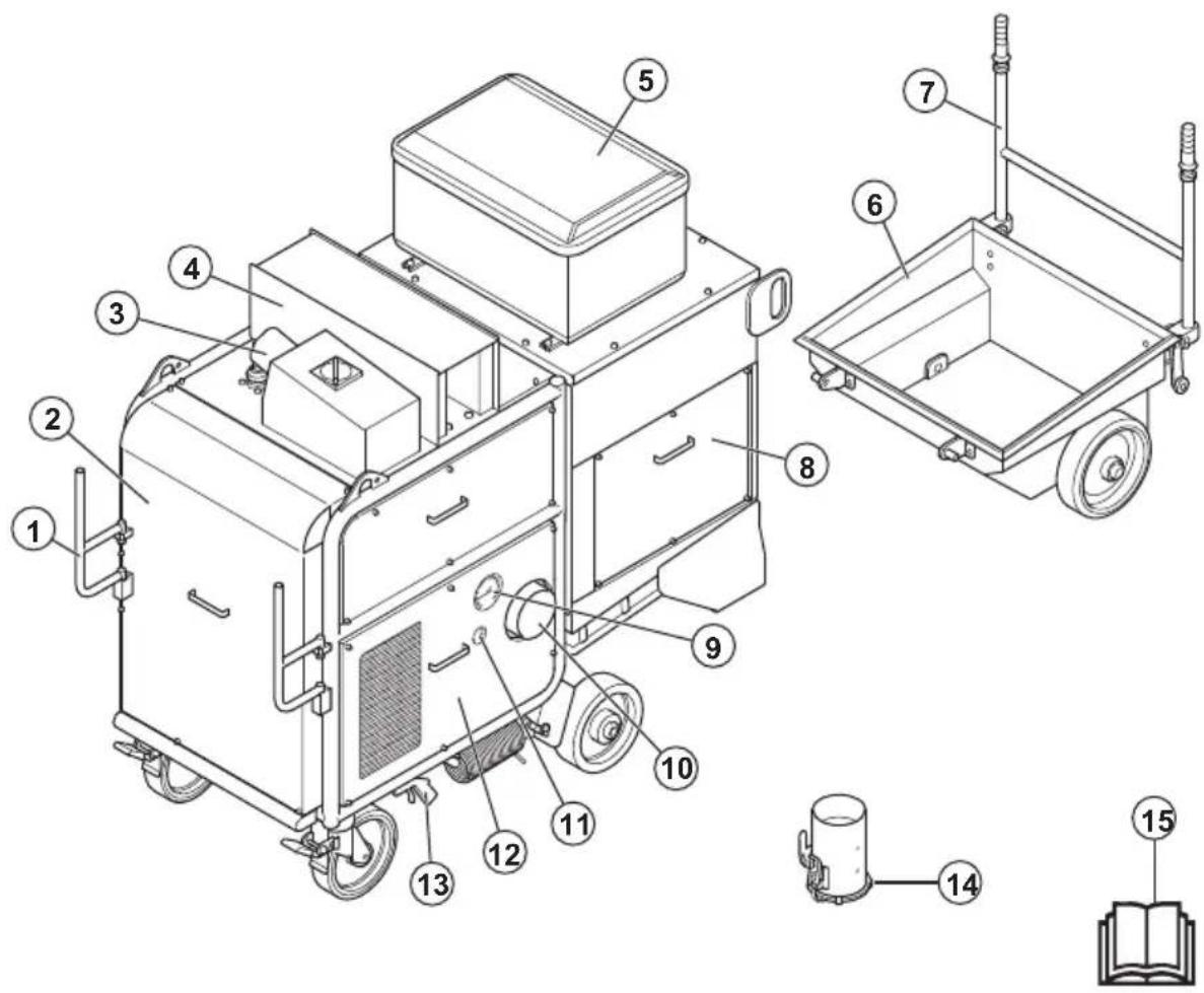
Technical diagram of a mechanical device with numbered components and exploded view, including labeled parts 1 through 15.- Cable support
- Front cover
- ATEX power connector socket with switch
- Silencer
- Control panel. Refer to Control panel overview on page 3.
- Dust container
- Dust container handle
- Filter cover
- Vacuum gauge
- Connection for dust collector hose adapter
- Pressure tank manometer
- Side cover
- Nozzle for pressurized air
- Dust collector hose adapter
- Operator's manual
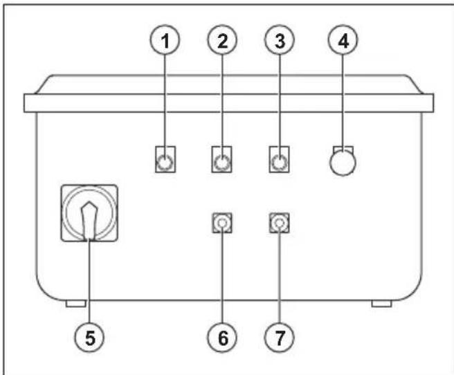
Control panel overview
All electrical components on the product are in the control panel. The control panel is ATEX approved.
text_image
① ② ③ ④ ⑤ ⑥ ⑦- Indicator for incorrect phase
- Indicator for air compressor and fan
- Indicator for motor failure
- Emergency stop button
-
ON/OFF switch and phase converter
-
Air compressor and fan OFF button
- Air compressor and fan ON button
Symbols on the product

Warning: This product can be dangerous and cause serious injury or death to the operator or others. Be careful and use the product correctly.
High voltage.
Lifting point.

Read the manual carefully and make sure that you understand the instructions before you use the product.

Use an approved respiratory protection.

Use approved hearing protection.

Use approved eye protection.

Use approved protective gloves.

Use approved protective boots.

This product is in compliance with applicable EU directives.
Note: Other symbols/decals on the product refer to special certification requirements for some markets.
Type plate
text_image
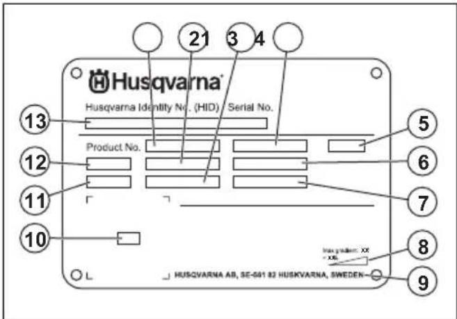
Husqvarna Husqvarna Identity No. (HID) Serial No. 13 Product No. 12 11 10 HUSQVARNA AB, SE-561 82 HUSKVARNA, SWEDEN- 21 3 4 5 6 7 8 9- Product number
- Product weight
- Rated power
- Rated voltage
- Phases
- Rated current
- Frequency
- Maximum slope angle
- Manufacturer
- Scannable code
- Production year
- Model
- Serial number
Product damage
We are not responsible for damages to our product if:
• the product is incorrectly repaired.
• the product is repaired with parts that are not from the manufacturer or not approved by the manufacturer.
• the product has an accessory that is not from the manufacturer or not approved by the manufacturer.
- the product is not repaired at an approved service center or by an approved authority.
Safety
Safety definitions
Warnings, cautions and notes are used to point out specially important parts of the manual.
WARNING: Used if there is a risk of injury or death for the operator or bystanders
if the instructions in the manual are not obeyed.

CAUTION: Used if there is a risk of damage to the product, other materials or the adjacent area if the instructions in the manual are not obeyed.
Note: Used to give more information that is necessary in a given situation.
General safety instructions

WARNING: Read the warning instructions that follow before you use the product.

CAUTION: Always read the manual and warning instructions of the diesel engine before you operate the product.
- This product is a dangerous tool if you are not careful or if you use the product incorrectly. This product can cause serious injury or death to the operator or others. Before you use the product, you must read and understand the contents of this operator's manual.
- This product is not intended for use by persons, including children, with reduced physical, sensory or mental capabilities, or lack of experience and knowledge.
- Save all warnings and instructions.
- Comply with all applicable laws and regulations.
- The operator and the employer of the operator must know and prevent the risks during operation of the product.
- Do not let a person operate the product unless they read and understand the contents of the operator's manual.
- Do not operate the product unless you receive training before use. Make sure that all operators receive training.
- Do not let a child operate the product.
- Only let approved persons operate the product.
- The operator is responsible for accidents that occur to other persons or their property.
- Do not use the product if you are tired, ill, or under the influence of alcohol, drugs or medicine.
- Operating the machine might lead to fatigue. It is important that the operator takes regular breaks.
• Always be careful and use your common sense. - Keep the product clean. Make sure that you can clearly read signs and decals.
-
Do not use the product if it is damaged or does not operate correctly.
-
Do not do modifications to this product.
- Do not operate the product if it is possible that other persons have done modifications to the product.
Safety instructions for operation

WARNING: Read the warning instructions that follow before you use the product.
- Use personal protective equipment. Refer to Personal protective equipment on page 6.
- Do not operate the product without all protective covers installed.
- Make sure that you know how to stop the motor quickly in an emergency.
- Before you go away from the product, stop the motor and disconnect the power cord. Make sure that there is no risk of accidental start.
- Keep hair, loose clothing and all body parts away from openings and moving parts.
- Make sure that you are in a safe and stable position during operation.
- Make sure that there are no loose bolts and nuts.
- Always use approved accessories. Speak to your Husqvarna dealer for more information.
- Make sure that the dust extraction hose is correctly attached to the product with hose clamps and industrial tape.
- Make sure that the parking brakes are engaged and that you are in a safe and stable position during operation.
- Regularly do a check of the contents of the dust storage system at the bottom of the product. Always wear a dust mask when you empty the dust storage system. Comply with the local regulations when you discard the dust.
- Do not point the dust extraction hose at persons.
- Make sure that there is no grease or oil on the handles.
- Do not use the product to collect water or liquids.
- Do not use the product to collect hot, burning or smoking objects.
- Do not use the product to collect flammable or combustible liquids.
- Do not use the product to collect explosive materials.
- Immediately stop the product if dust comes out the filter unit. The primary filters are damaged or not correctly installed.
- Do not use without dust bag and/or filters in place. Replace the dust bag and filters system as given in this manual.
Dust safety
WARNING: Read the warning instructions that follow before you use the product.
- Operation of the product can cause dust in the air. Dust can cause serious injury and permanent health problems. Silica dust is regulated as harmful by several authorities. These are examples of such health problems:
• The fatal lung diseases chronic bronchitis, silicosis and pulmonary fibrosis
- Cancer
- Birth defects
- Skin inflammation
- Use correct equipment to decrease the quantity of dust and fumes in the air and to decrease dust on work equipment, surfaces, clothing and body parts. Example of controls are dust collection systems. Decrease dust at the source where possible. Make sure that the equipment is correctly installed and used and that regular maintenance is done.
- Use approved respiratory protection. Make sure that the respiratory protection is applicable for the dangerous materials in the work area.
- Make sure that the airflow is sufficient in the work area.
- It is the responsibility of the user to analyse the surface to be treated. The surface may not contain any substances which could pose a fire-, explosion or health risk when treated. The user should make a risk assessment on the basis of the information obtained about the surface to be treated and take proper precautions for the work to be performed.
Noise safety

WARNING: Read the warning instructions that follow before you use the product.
- High noise levels and long-term exposure to noise can cause noise-induced hearing loss.
- To keep the noise level to a minimum, do maintenance on and operate the product as given in the operator's manual.
- Use approved hearing protection while you operate the product.
- Listen for warning signals and voices when you use hearing protection. Remove the hearing protection when the product is stopped, unless hearing protection is necessary for the noise level in the work area.
Personal protective equipment
WARNING: Read the warning instructions that follow before you use the product.
• Always use approved personal protective equipment when you operate the product. Personal protective equipment cannot fully prevent injury but it decreases the degree of injury if an accident does
occur. Let your dealer help you select the correct personal protective equipment and when to use them.
- Regularly do a check of the condition of the personal protective equipment.
- Use approved hearing protection.
- Use approved respiratory protection.
- Use approved eye protection with side protection.
- Use protective gloves.
- Use boots with steel toe-cap and non-slip sole.
- Use approved work clothing or equivalent close-fitting clothing that has long sleeves and long legs.
Work area safety

WARNING: Read the warning instructions that follow before you use the product.
- Do not use the product in fog, rain, strong winds, cold weather, risk of lightning or other bad weather conditions.
- Keep children, bystanders and animals away from the work area and at a distance of minimum 5 m/17 ft. from the product.
- Make sure that only approved persons are in the work area.
- Keep work area clean and well lit. Cluttered or dark areas invite accidents.
- Make sure that rough surfaces, for example welded seams or floor joints, do not stop the product.
- Make sure that there are no cables or hoses in the operation direction of the product.
- Make sure that there is sufficient airflow in the work area.
- Make sure that there are no flammable liquids in the work area.
- This appliance is not suitable for use in classified (hazardous) locations, to pick up dusts or liquids of high explosion risk, nor mixtures of combustible dust with liquids.
- Do not pick up anything that is burning or smoking, such as cigarettes, matches, or hot ashes.
- Do not use to pick up flammable liquids, such as gasoline, or use in areas where flammable vapors may be present.
Electrical safety

WARNING: There is always a risk of shocks from electrical products. Do not use the product in bad weather conditions. Do not touch lightning conductors and metal objects. Always use the product as given in this operator's manual to prevent injury.

WARNING: Always use a power supply with RCD (residual-current device). An RCD decreases the risk of electrical shock.

WARNING: High voltage. There are unprotected parts in the power unit. Always disconnect the power plug before you open the door to the electrical box.

WARNING: Only use the socket outlets on the product for purposes specified in the instructions.

CAUTION: The power supply from the product or generator must be sufficient and constant to make sure that the motor operates without problems. Incorrect voltage causes the power consumption and the temperature of the motor to increase until the safety circuit releases. The dimension of the power cord must agree with national and local regulations. The dimension of the mains socket must agree with the amperage for the electrical socket and extension cable of the product.
If the power mains has higher system resistance, short voltage drop can occur when the product is started. This can influence the operation of other products, for example flicker on the lights.
- The power plug must match the outlet. Never modify the plug in any way. Do not use any adapter plugs with earthed (grounded) power tools. Unmodified plugs and matching outlets will reduce risk of electric shock.
- Avoid body contact with earthed or grounded surfaces, such as pipes, radiators, ranges and refrigerators. There is an increased risk of electric shock if your body is earthed or grounded.
- Make sure that the power, fuse and mains voltage are the same as the voltage shown on the rating plate of the product.
• Always stop the product before you disconnect the power plug. - Make sure that the ON/OFF switch is in OFF position before the product is connected to the power supply.
- Always disconnect the power plug during a long product stop.
-
Do not use the product if the supply cord or power plug is damaged. If the supply cord is damaged, it must be replaced by the manufacturer, its service agentor similarly qualified persons in order to avoid a hazard. A damaged power cord can cause serious injury and death.
-
Use the power cord correctly. Do not use the power cord to move, pull or disconnect the product. Pull the power plug to disconnect the power cord. Do not pull the power cord.
- Only operate the product on dry surfaces.
- Keep the product away from rain. Water that goes into the product increases the risk of electrical shock.
- Always disconnect the power cord before you connect or disconnect the connection for the motor cable and the electrical enclosure.
- In order to avoid a hazard due to inadvertent resetting of the thermal cut-out, this appliance must not be supplied through an external switching device, such as a timer, or connected to a circuit that is regularly switched on and off by the utility.
- Make sure that the power supply for the product is supplied by separate transformers that are used for industrial purpose only.
Grounded product instructions

WARNING: Incorrect connection can result in electrical shock. Speak to an approved electrician if you are not sure if your mains outlet is correctly grounded.
Do not do modifications to the power plug from its factory specification. If the power plug or power cord is damaged or must be replaced, speak to your Husqvarna service agent. Obey local regulations and laws.
If you do not fully understand the instructions about the grounded product, speak to an approved electrician.
Use only grounded outdoor extension cables with grounding plugs and grounding outlet that accepts the product power plug.
The product has a grounded power cord and power plug. Always connect the product to a grounded mains outlet. This decreases the risk of electrical shock.
Do not use electrical adapters with the product.
Extension cables
- Use only approved extension cables with applicable properties.
- The rated value on the extension cable must be the same or higher than given on the rating plate of the product.
- Use grounded extension cables.
- When you operate the product outdoors, use an extension cable that is applicable for outdoor operation. This decreases the risk of electrical shock.
-
Keep the connection to the extension cable dry and off the ground.
-
Keep the extension cable away from heat, oil, sharp edges or moving parts. A damaged cable increases the risk of electrical shock.
- Make sure that the extension cable is in good condition and not damaged.
- Do not use the extension cable while it is wound up. This can cause the extension cable to become too hot.
- Make sure that the extension cable is out of the way and the product during operation. This prevents damage to the extension cable.
Safety devices on the product

WARNING: Read the warning instructions that follow before you use the product.
- Do not use the product if the safety devices are damaged or does not operate correctly.
- Do a check of the safety devices daily. If your safety devices are damaged or does not operate correctly, speak to your Husqvarna service agent.
- Do not make modifications on safety devices
Emergency stop button
The emergency stop button is used to quickly stop the product and breaks the mains power supply.
To do a check of the emergency stop button
Refer to Control panel overview on page 3 for information about where the emergency stop button is on your product.
- Turn the emergency stop button clockwise to make sure that the emergency stop button is disengaged.
- Start the product. Refer to To start the product on page 10.
- Push the emergency stop button.
- Make sure that the motor stops.
- Turn the emergency stop button clockwise to disengage.
Motor protection switch
The product has multiple motor protection switches to prevent motor overload. Let an electrician do a check of the motor protection switches if there is a motor overload.
Safety instructions for maintenance

WARNING: Read the warning instructions that follow before you do maintenance on the product.
- Product related accidents can occur during the troubleshooting, servicing and maintenance as the
operator must be in the risk area of the product. The operator must be careful, make a plan and prepare the work to prevent accidents.
- If the maintenance is not done correctly and regularly, the risk of injury and damage to the product increases.
- Use personal protective equipment. Refer to Personal protective equipment on page 6.
- Disconnect the product from the power source before you do the maintenance.
- Do not make modifications to the product. Modifications that are not approved by the manufacturer can cause serious injury or death.
• Always use original accessories and spare parts. Accessories and spare parts that are not approved by the manufacturer, can cause serious injury or death.
- Replace damaged, worn or broken parts.
- Only do the maintenance as given in this operator's manual. Let an approved service agent do all other servicing.
- If the replacement of the supply cord is necessary, this has to be done by the manufacturer or his agent in order to avoid a safety hazard.
- Only let an approved electrician do all checks of the electric components.
- Be careful when you handle the filters. If you damage the filters, there is a risk of dust dispersion. Always use approved respiratory protection. Refer to Personal protective equipment on page 6.
- The manufacturer, or an instructed person, must do a technical inspection at least annually. The technical inspection includes an inspection of the filters for damage, air tightness of the product and correct function of the control mechanism. In addition, the filtration efficiency of the product must be tested at least annually, or more frequently as may be specified by national requirements. If the test is not conducted the main filters must be replaced by new ones.
- When carrying out service or repair operations, all contaminated items which cannot be satisfactorily cleaned are to be disposed of; such items shall be disposed of in impervious bags in accordance with any current regulation for the disposal of such waste.
- All the machine parts shall be regarded as contaminated when removed from the working area and appropriate action taken to prevent dust dispersal.
- The outside of the machine should be decontaminated by vacuum cleaning methods and wiped clean or treated with sealant before being taken out of a working area.
- For user servicing, the machine shall be dismantled, cleaned and serviced, as far as is reasonably practicable, without causing risk to the maintenance staff and others. Suitable precautions include decontamination before dismantling, provision for local filtered exhaust ventilation where the machine
is dismantled, cleaning of the maintenance area and suitable personal protection.
- It is necessary to provide for an adequate AIR CHANGE RATE ACR in the room if the exhaust
air is returned to the room. Refere to National regulations.
Operation
Introduction
WARNING: Before you operate the product, you must read and understand the safety chapter.
To do before you operate the product
WARNING: To prevent the risk of injury, make sure that you attach the product plug fully to the extension cable. Do regular checks of the connection while you operate the product to make sure that it is fully attached. Do not use an extension cable that makes a loose connection.
Note: Read the operator's manual of the attached equipment carefully. If specified requirements or settings are given for the secondary product, make sure that you obey these.
- Read the operator's manual carefully and make sure that you understand the instructions.
- Do the daily maintenance. Refer to Maintenance schedule on page 11.
- Make sure that the work area is clean and bright.
- Use personal protective equipment. Refer to Personal protective equipment on page 6.
- Make sure that the product is installed correctly.
- Make sure that the frequency and voltage shown on the type plate agrees with the power supply voltage. This is also applicable for the extension cables.
- Make sure that the power plug is connected correctly.
To attach the dust collector hose
- Install the dust collector hose adapter on the air intake.
natural_image
Technical line drawing of a mechanical clamp or bracket assembly with no visible text or symbols- Attach the dust collector hose with hose clamps and industrial tape.
a) For hoses with 150 mm/6 in. diameter, attach the dust collector hose around the dust collector hose adapter.
b) For hoses with 130 mm/5 in. diameter, attach the dust collector hose adapter around the dust collector hose.
To engage and disengage the parking brake
The parking brake must be engaged before you start the product.
• To disengage the parking brake, push the lock lever up.
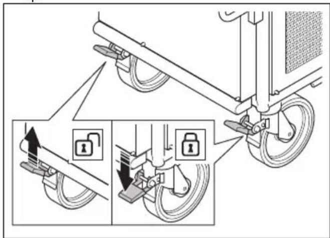
text_image
Diagram illustrating bicycle suspension system with lock mechanism and safety instructions• To engage the parking brake, push the lock lever down.
Water separator
The water separator removes dirt, oil and water from the air. Moist and dirty air decrease the life of the primary filters. Empty the water separator daily or when the water level is 10 mm below the level indicator mark. Refer to To drain the water from the water separator on page 19.
Vacuum gauge
The vacuum gauge shows the condition of the primary filters. If the value on the vacuum gauge is 20 cmH2O or higher, it is necessary to clean the primary filters.
Pressure tank manometer
The pressure tank manometer shows the pressure in the pressure tank. The air in the pressure tank cleans the primary filters. The pressure is approximately 7 bar/100 PSI during operation.
To connect a secondary product
- Connect the power plug of the secondary product to an applicable power supply or to the ATEX power connector socket on the product.
CAUTION: Make sure that the power plug of the secondary product is fully connected to the ATEX power socket.
-
Make sure that the dust extraction hose between the product and the secondary product is connected with hose clamps and industrial tape.
-
Make sure that the dust extraction hose is in good condition and can move freely.
To connect the product to a power source
-
Connect the power plug of the product to a grounded mains outlet or other power source.
-
Make sure that the mains voltage agrees with the type plate on the product.
To start the product
-
Connect the dust extraction hose between the product and the secondary product. Refer to To attach the dust collector hose on page 9 and To connect a secondary product on page 10.
-
Connect the product to a power supply. Refer to To connect the product to a power source on page 10.
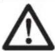
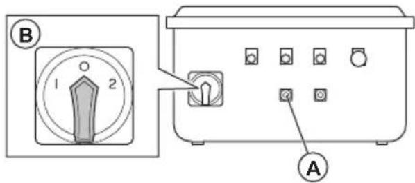
-
Set the ON/OFF switch to the "1" position (A).
text_image
A C D 1 2 B E- Look at the indicator for incorrect phase (B). If the indicator is on, do the steps that follow to change the phases:
a) Set the ON/OFF switch to the "0" position (C). b) Set the ON/OFF switch to the "2" position (D). c) Make sure that the indicator for incorrect phase is off.
- Push the ON button for the air compressor and the fan (E).
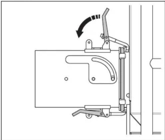
To stop the product
- If you stop the product temporarily, close the air intake valve in the dust collector hose adapter.
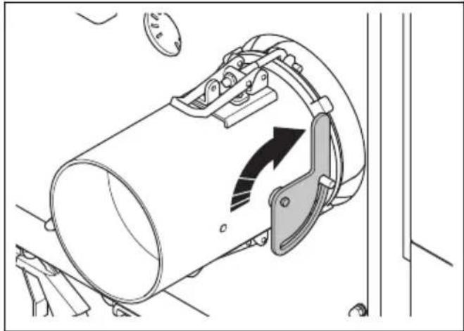
natural_image
Technical diagram of a mechanical clamp or bracket assembly with directional arrows indicating motion (no text or symbols present)Note: When the air compressor and the fan are on during a short stop, the product cleans the primary filters.

WARNING: Always close the air intake valve in the dust collector hose adapter when you stop the product temporarily. If the air intake is not closed, dust goes into the air. The dust particles are dangerous to your health.
- If you stop the product for more than 1 hour, do the steps that follow:
a) Close the air intake valve.
b) After 5 minutes, push the OFF button for the air compressor and the fan (A).
text_image
B 1 2 Ac) Set the ON/OFF switch to the position "0" (B).
d) Disconnect the power plug from the power supply.
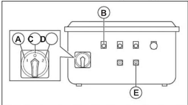
To empty the dust container
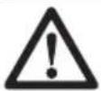
WARNING: Be careful when you empty the dust container, a full dust container can be heavy.

WARNING: Use approved respiratory protection when you empty the dust container. Refer to Personal protective equipment on page 6.
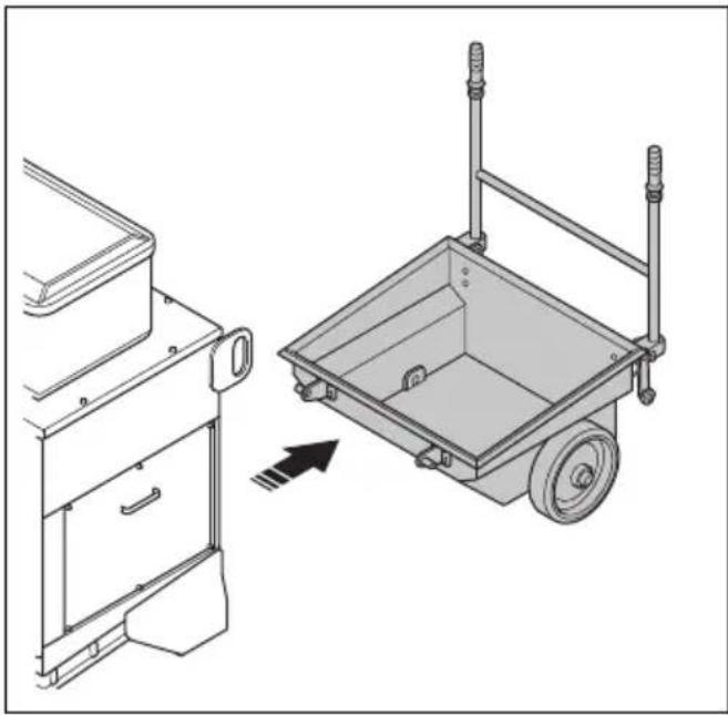
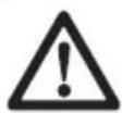
- Turn the handles to release the lockpins.
natural_image
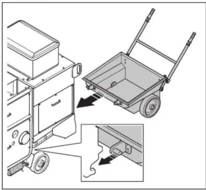
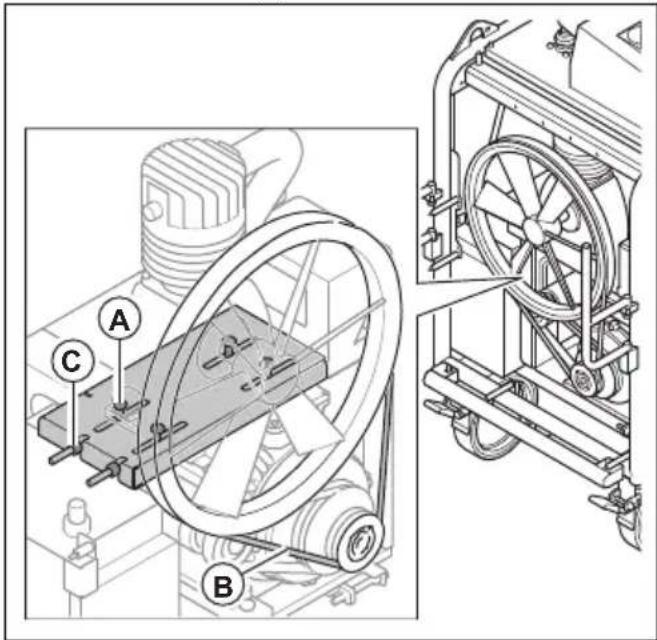
Technical line drawing of a mechanical device with mounting brackets and a close-up inset showing internal components (no text or symbols)- Remove the dust container.
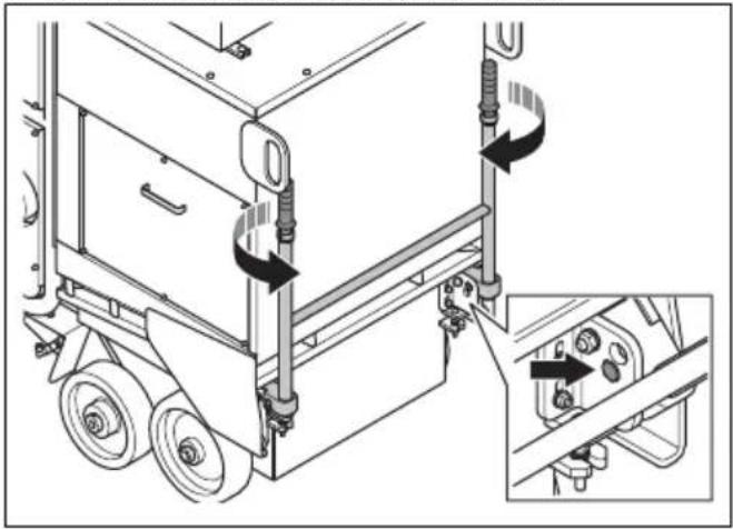
natural_image
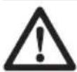
Technical line drawing of a two-part mechanical device with a pull-up view showing the front panel and side panel (no text or symbols)-
Obey local regulations for disposal of the contents of the dust container.
-
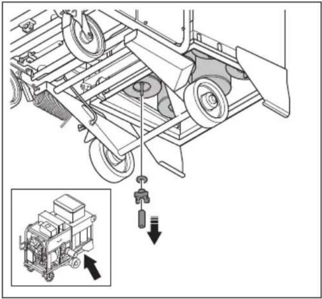
Install the dust container in the opposite sequence. Make sure that the dust container is correctly installed.
natural_image
Technical illustration of a mechanical device with a pull-up of a wheelbarrow and a close-up view of the component (no text or symbols present)
WARNING: If the dust container is not correctly installed, dust can go into the air.
Maintenance
Introduction
WARNING: Read and understand the safety chapter before you do maintenance on the product.
Maintenance schedule
* = General maintenance done by the operator. The instructions are not given in this operator's manual.
X = The instructions are given in this operator's manual.
O = The instructions are not given in this operator's manual. Let an approved service agent do the maintenance.
| General product maintenance Daily Weekly | Each 3 months | Yearly | Each 2 years | ||
| Make sure that the power plug and extension cable are in good condition and not damaged. | * | ||||
| Do a check of the electrical components, the cables, and the connections for wear and damages. | * | ||||
| Examine the electric motor for dirt and damage. | * | ||||
| Make sure that the dust extraction hose is not damaged or blocked. | * | ||||
| Empty the dust container. X | |||||
| Make sure that the dust extraction hose is correctly installed. | X | ||||
| Dispose dust from the product. X | |||||
| Do a check of all safety devices. X | |||||
| Drain water from the water separator. X | |||||
| Drain water from the pressure tank. X | |||||
| Do a check of the oil level in the air compressor. ^1 | X | ||||
| Clean the air compressor filter. X | |||||
| Clean the filter of the water separator. Replace if it is necessary. | X | ||||
| Do a check of the V-belt tension. X | |||||
| Clean the top section of the filter unit. O | |||||
| Replace the air compressor filter. X | |||||
| Do a complete servicing and cleaning of the product. | O | ||||
| Replace the oil in the air compressor. ^2 | X |
To clean the product
• Always clean all the equipment after use. Use a vacuum cleaner.
- Do not use a high-pressure washer to clean the product.
- Keep the air openings clean and clear to make sure that the product always has sufficient air flow.
To clean the air compressor filter
CAUTION: Do not use a high-pressure washer or water to clean the air compressor filter.
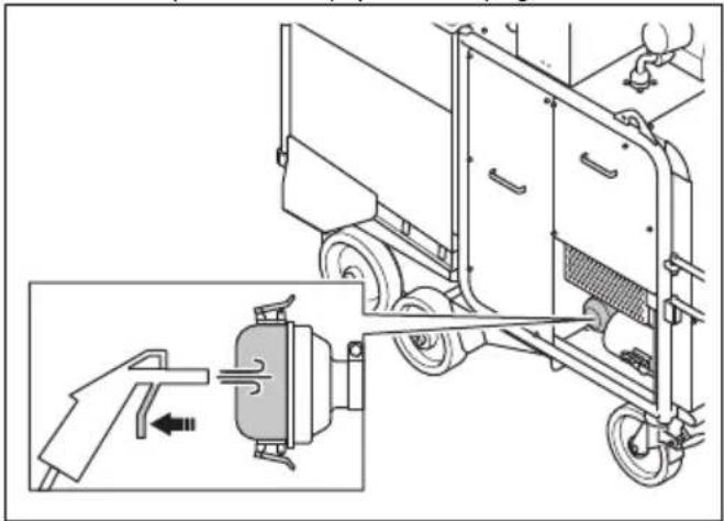
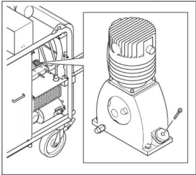
- Clean the front of the filter housing with pressurized air. Use approved respiratory protection. Refer to Personal protective equipment on page 6.
natural_image
Technical diagram of a vehicle's internal components and assembly, showing a hand operating a valve and a motor assembly (no text or labels)- Open the filter housing.
text_image
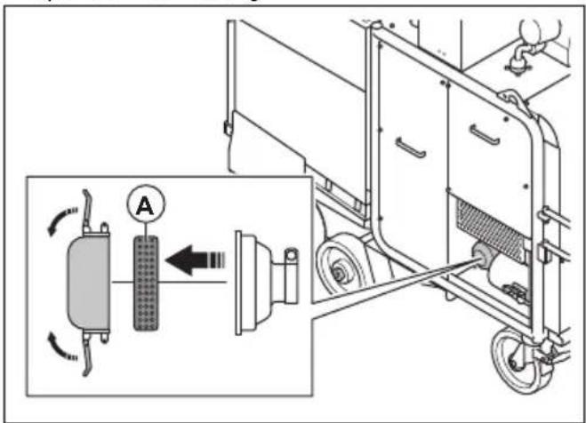
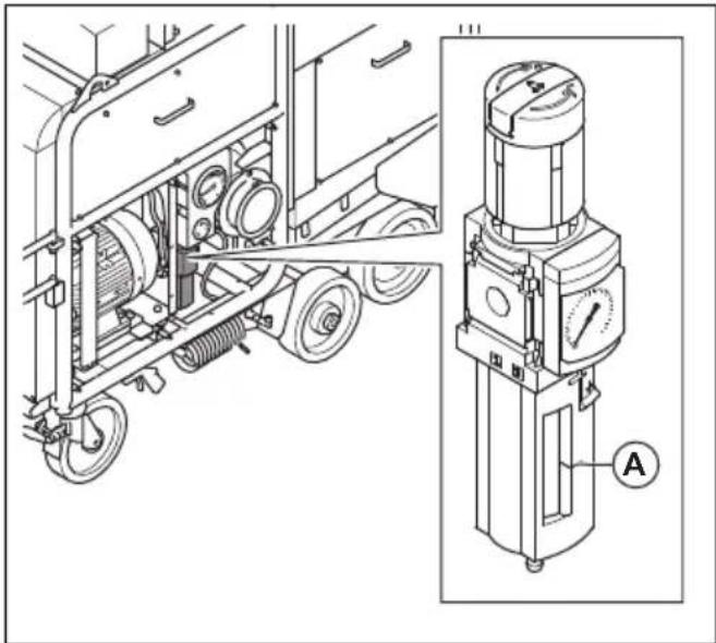
Technical diagram showing a mechanical assembly with labeled components and directional arrows, including a magnified inset of a component labeled 'A'.-
Remove the air compressor filter (A).
-
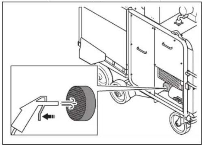
Clean the air compressor filter with pressurized air. Use approved respiratory protection. Refer to Personal protective equipment on page 6.
natural_image
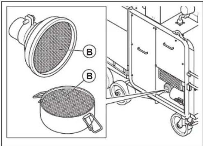
Technical illustration of a vehicle chassis with a hand operating a wheel, showing internal components and motion direction (no text or symbols)- Clean the 2 halves (B) of the filter housing with a lint-free cloth.
natural_image
Technical illustration of a kitchen appliance with labeled parts (no text or symbols present)Replace the air compressor filter if you cannot fully clean it or if it is damaged.
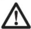
To clean the filter in the water separator
-
Stop the product. Refer to To stop the product on page 10.
-
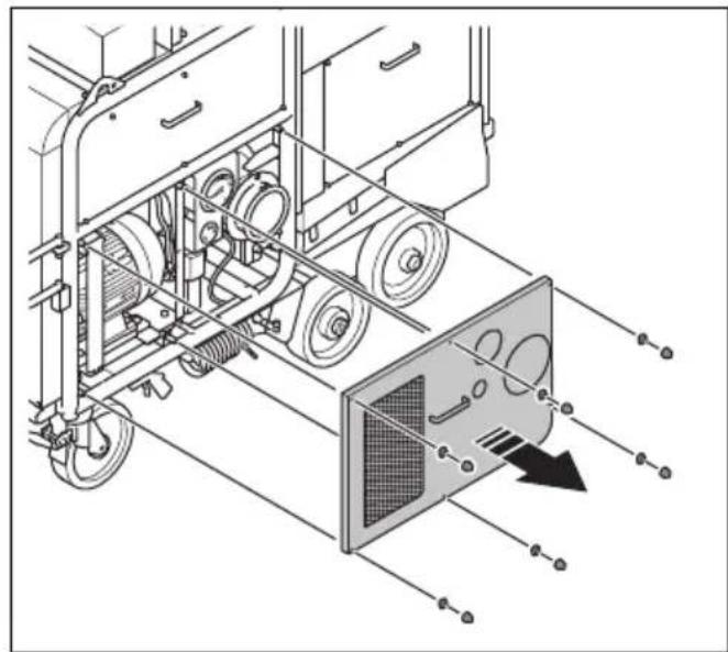
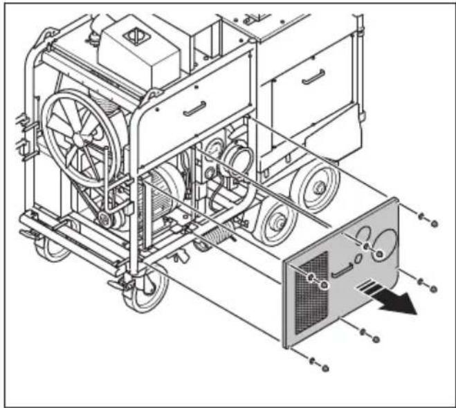
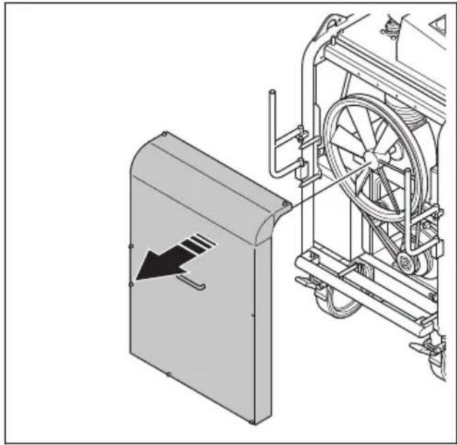
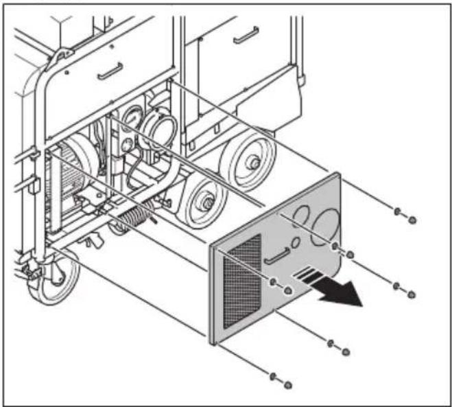
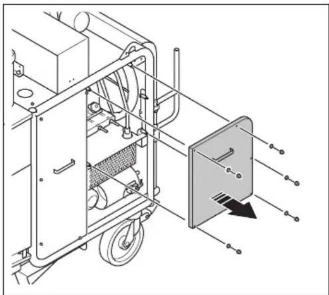
Remove the 6 nuts, the 6 washers and the left side cover.
natural_image
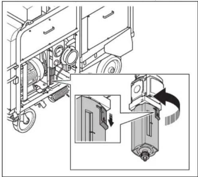
Technical line drawing of a vehicle chassis with wheels and a panel, showing internal components and motion arrows (no text or symbols)- Push down the lock button on the water separator, turn the filter bowl counterclockwise and pull it down.
natural_image
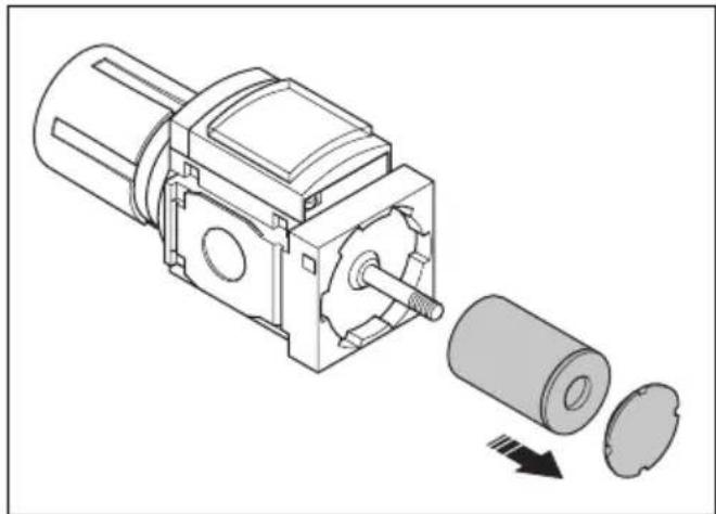
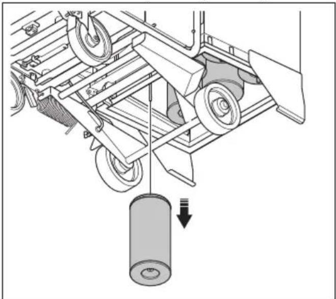
Technical illustration of a mechanical assembly with exploded view and close-up detail (no text or symbols)- Remove the filter screw and the filter.
natural_image
Technical illustration of a mechanical assembly showing a motor and a cylindrical component with a downward arrow indicating motion (no text or symbols present)- Clean the filter with warm water.
- Dry the filter with pressurized air.
- Install the filter and the filter screw.
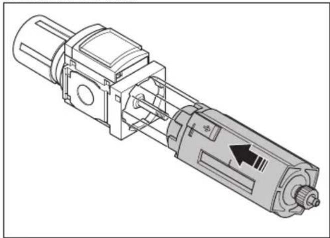
- Install the filter bowl.
natural_image
Technical line drawing of a mechanical device with internal components and a directional arrow (no text or symbols)- Turn the filter bowl clockwise until you hear a click.
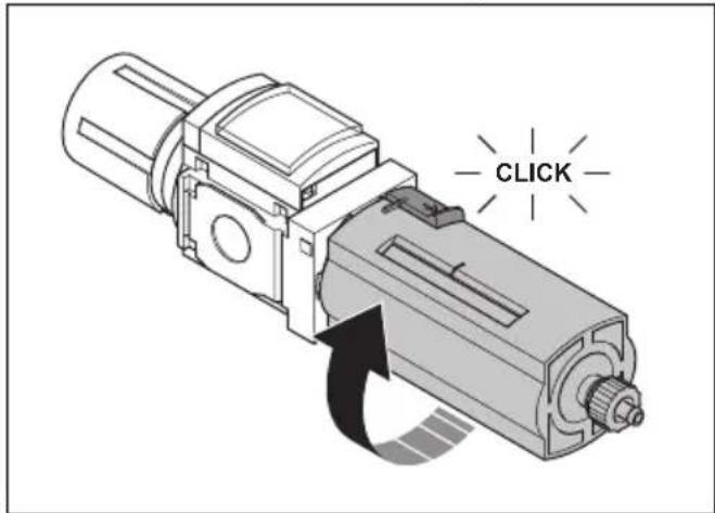
text_image
CLICKReplace the filter in the water separator if you cannot fully clean it or if it is damaged.
To clean the primary filters

WARNING: Always close off the air intake when the pulse cleaning cycle runs. If the air intake is not closed, dust can come in to the air. The dust particles are dangerous to your health.
- Start the product. Refer to To start the product on page 10.
- Stop the fan. Refer to To stop the product on page 10.
- Keep the air compressor on for 30 minutes while the product is not in operation. Pressurized air goes through the primary filters and cleans them.
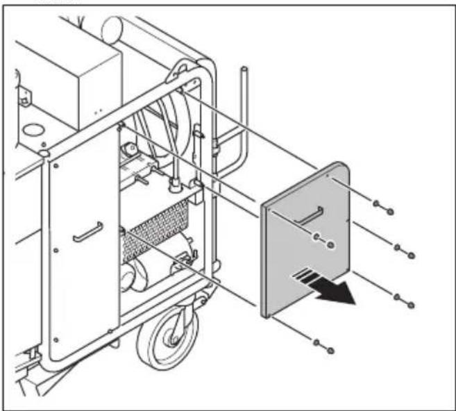
To replace the primary filters
WARNING: Be careful when you remove the primary filters. The particles in the primary filters are dangerous to your health. Always use personal protective equipment when you replace the primary filters. Refer to Personal protective equipment on page 6.
CAUTION: Replace all 6 primary filters at the same time.
- Stop the product. Refer to To stop the product on page 10.
-
Remove the dust container. Refer to To empty the dust container on page 11.
-
Remove the nut, the knob and the rubber seal.
natural_image
Technical line drawing of a mechanical lifting device with an inset showing a zoomed-in view of the component (no text or symbols present)- Remove the filter and put it in a plastic bag.
natural_image
Mechanical assembly diagram showing a cart with wheels and a pulley system (no text or symbols)-
Discard the plastic bag with the primary filter correctly. Refer to local regulations.
-
Install the new filter, the rubber seal, the knob and the nut.

WARNING: If the primary filters are not installed correctly, dust can come in to the air. The dust particles are dangerous to your health.
- Do the same replacement procedure on the other 5 primary filters.
To do a check of the tension in the V-belts
The product has 2 V-belts: 1 for the motor and 1 for the air compressor.

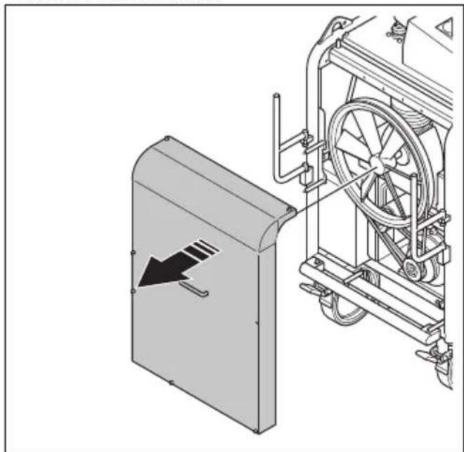
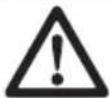
WARNING: Only remove the front cover when the product is disconnected from the mains outlet and the motor has fully stopped.

WARNING: Do not operate the product without the front cover installed.
-
Stop the product. Refer to To stop the product on page 10.
-
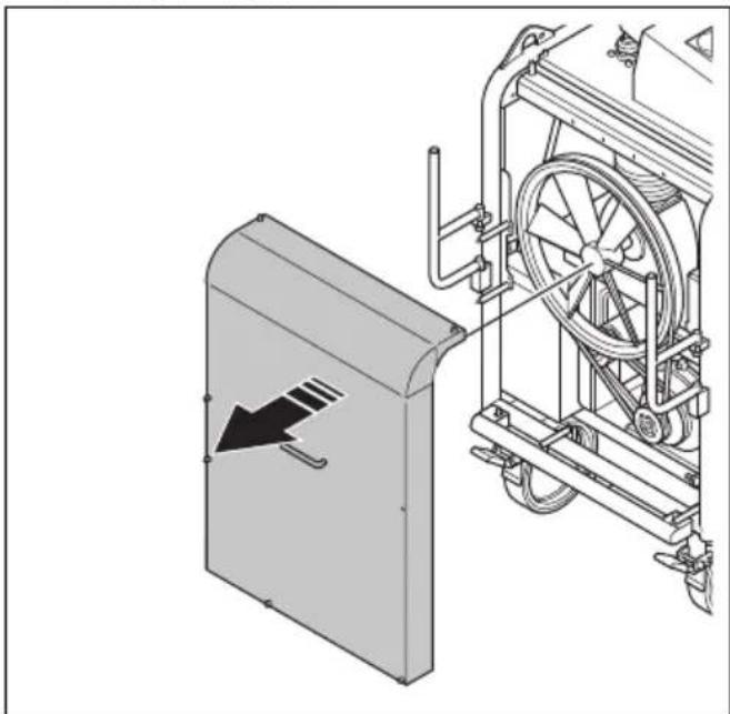
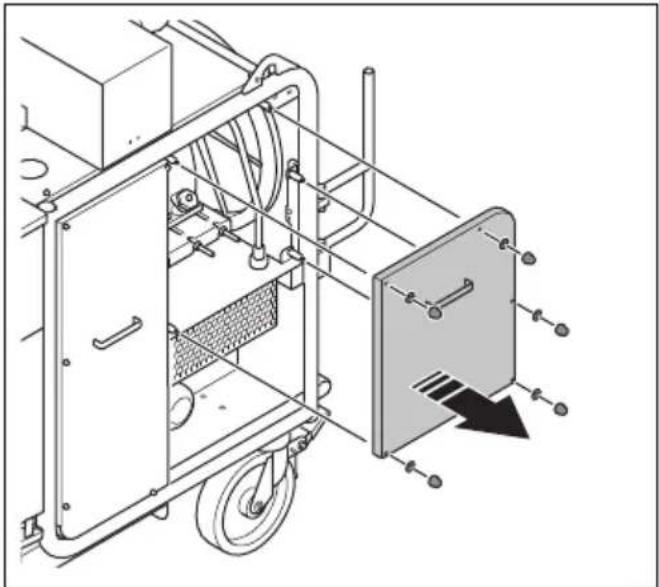
Remove the front cover.
natural_image
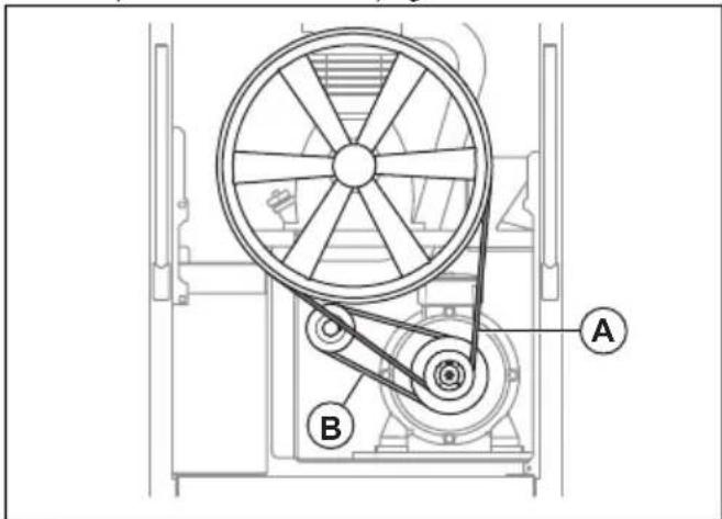
Technical illustration of a mechanical device with a directional arrow indicating motion, showing internal components and no visible text or symbols.- Examine the V-belts (A) and (B) for damages and wear. Replace the V-belts if it is necessary. Refer to To replace the V-belts on page 17.
text_image
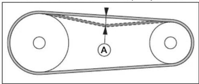
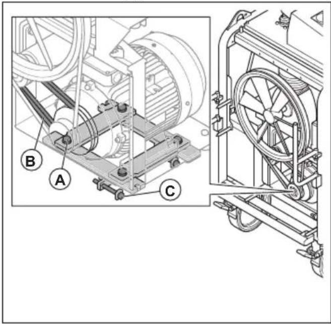
Technical diagram of a mechanical device with labeled components A and B, showing wheel and pulley system.- Push the V-belts with your thumb to examine the tension. If you can push the V-belts a distance of 10–15 mm (A), the tension is correct. If you use a belt tension instrument the correct frequency is 70 Hz.
text_image
Diagram of a belt drive system with pulleys and belt, labeled point A-
Adjust the tension of the V-belts if it is necessary. Refer to To adjust the tension in the V-belt for the motor on page 16 or To adjust the tension in the V-belt for the air compressor on page 17.
-
Install the front cover.
To adjust the tension in the V-belt for the motor
WARNING: Only remove the front cover when the product is disconnected from the mains outlet and the motor has fully stopped.

WARNING: Do not operate the product without the front cover installed.
-
Stop the product. Refer to To stop the product on page 10.
-
Remove the front cover.
natural_image
Technical illustration of a mechanical device with a directional arrow indicating motion, showing internal components and assembly (no text or symbols)- Remove the 6 nuts, the 6 washers and the left side cover.
natural_image
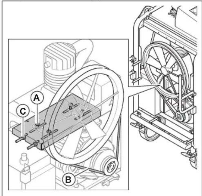
Technical line drawing of a mechanical device with wheels and a panel, showing internal components without any text or symbols.- Loosen the 4 bolts (A).
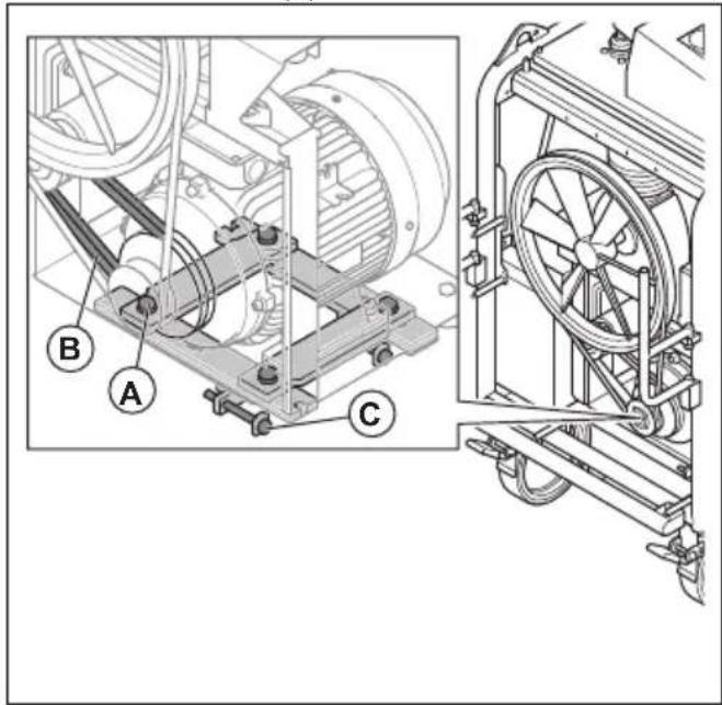
text_image
Technical diagram of a mechanical assembly with labeled parts A, B, and C, showing internal components and external view.- To increase the tension in the V-belt for the motor (B), loosen the 2 bolts (C). To decrease the tension, tighten the bolts (C).
CAUTION: This procedure also adjusts the tension in the V-belt for the air compressor.
-
Do a check of the tension in the V-belt for the air compressor. Refer to To adjust the tension in the V-belt for the air compressor on page 17.
-
If it is necessary, adjust the tension in the V-belt for the air compressor. Refer to To adjust the tension in the V-belt for the air compressor on page 17.
-
Install the front cover and the left side cover.
To adjust the tension in the V-belt for the air compressor

WARNING: Only remove the front cover when the product is disconnected from the mains outlet and the motor has fully stopped.

WARNING: Do not operate the product without the front cover installed.
- Stop the product. Refer to To stop the product on page 10.
- Remove the front cover.

natural_image
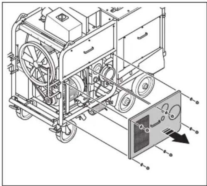
Technical illustration of a mechanical device with a directional arrow indicating motion, showing internal components and no visible text or symbols.- Remove the 5 nuts, the 5 washers and the right side cover.
natural_image
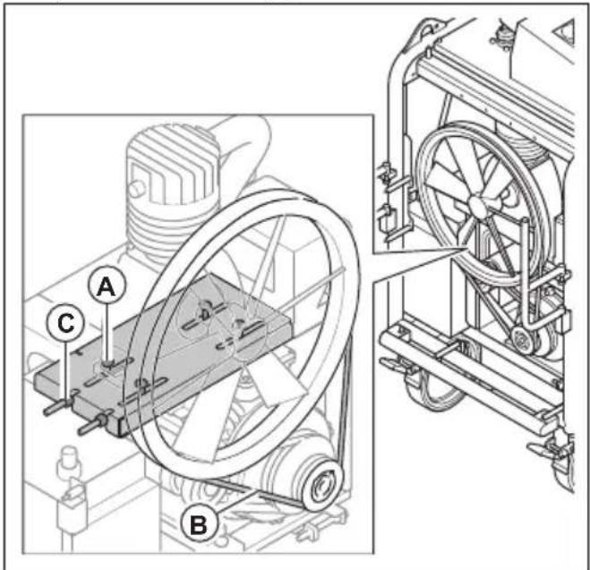
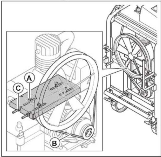
Technical line drawing of a mechanical device with wheels and a panel, showing no text or symbols- Loosen the 4 bolts (A).
text_image
Technical diagram of a mechanical device with labeled components A, B, and C, showing internal components and assembly details.- To increase the tension in the V-belt for the air compressor (B), loosen the 2 bolts (C). To decrease the tension, tighten the 2 bolts (C).
- Install the front cover and the right side cover.
To replace the V-belts
WARNING: Only remove the front cover when the product is disconnected from the mains outlet and the motor has fully stopped.
WARNING: Do not operate the product without the front cover installed.
-
Stop the product. Refer to To stop the product on page 10.
-
Remove the front cover.
natural_image
Technical illustration of a mechanical device with a directional arrow indicating motion (no text or symbols present)- Remove the 6 nuts, the 6 washers and the left side cover.
natural_image
Technical line drawing of a mechanical device with wheels and a panel, showing internal components without any text or symbols.- Remove the 5 nuts, the 5 washers and the right side cover.
natural_image
Technical line drawing of a mechanical device with wheels and a panel, showing no text or symbols- Do the steps that follow to replace the V-belt for the motor:
a) Loosen the 4 bolts (A).
text_image
Technical diagram of a mechanical device with labeled components A, B, and C, showing internal components and external fan assembly.b) Loosen the 2 bolts (B) until there is no tension in the V-belt for the motor.
c) Replace the V-belt for the motor.
d) Adjust the tension in the V-belt for the motor.
Refer to To adjust the tension in the V-belt for the motor on page 16.
- Do the steps that follow to replace the V-belt for the air compressor:
a) Loosen the 4 bolts (A).
text_image
Technical diagram of a mechanical device with labeled components A, B, and C, showing internal components and external view.b) Loosen the 2 bolts (B) until there is no tension in the V-belt for the air compressor.
c) Replace the V-belt for the air compressor.
d) Adjust the tension in the V-belt for the air compressor. Refer to To adjust the tension in the V-belt for the air compressor on page 17.
- Install the front cover and the 2 side covers.
To drain the water from the water separator
- Stop the product. Refer to To stop the product on page 10.
- Remove the 6 nuts, the 6 washers and the left side cover.
natural_image
Technical line drawing of a vehicle chassis with wheels and a door panel, showing internal components without any text or symbols.- Do a check of the water level in the water separator. It is necessary to drain the water separator when water level is 10 mm below the level indicator mark (A), or after 200 h of operation.
natural_image
Technical line drawing of a truck-mounted industrial machine with attached pressure gauge (no text or symbols)- Put a container below the water separator to collect the water.
- Push the outlet ring (B) up.
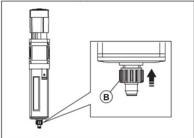
text_image
Technical diagram showing a mechanical assembly with labeled component B and directional arrow- Release the outlet ring when all the water is drained.
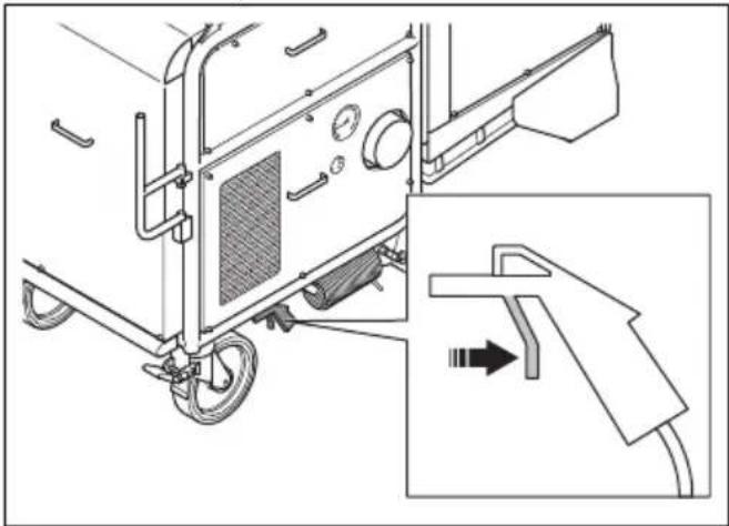
To drain the water from the pressure tank
You must drain water from the pressure tank daily. Use the pressure in the product to drain the water from the pressure tank.
- Start the product. Refer to To start the product on page 10.
-
Look at the manometer. Wait until the pressure is 7 bar.
-
Operate the nozzle for pressurized air. The water drains from the nozzle for pressurized air. Drain the water until the pressure is 0 bar.
natural_image
Technical line drawing of a vehicle chassis with attached components and a close-up inset showing a hand holding a tool (no text or symbols present)To do a check of the oil level in the air compressor
CAUTION: A too low oil level can do damage to the engine. Do a check of the oil level before you start the product.
Do a check of the oil level in the air compressor each 50 hours of operation during the 300 first hours of operation. The product uses more oil for the air compressor during the first period of operation. After the first 300 hours of operation, do a check of the oil level in the air compressor weekly.
- Put the product on level ground.
- Remove the 5 nuts, the 5 washers and the right side cover.
natural_image
Technical line drawing of a mechanical device with wheels and a panel, showing no text or symbols- Remove the oil dipstick from the oil fill plug.
natural_image
Technical line drawing of industrial equipment including a motor and a cylindrical housing (no text or symbols)- Clean the oil from the dipstick.
- Put the dipstick fully into the oil tank.
- Remove the dipstick.
-
Examine the oil level on the dipstick.
-
If the oil level is low, fill with oil and do a check of the oil level again. Refer to Technical data on page 24 for the correct type of oil.
To replace the oil in the air compressor
Replace the oil in the air compressor after the first 300 hours of operation. After this, replace the oil in the air compressor each 2 years.
- Start the product. Refer to To start the product on page 10.
- Let the product become warm.
- Stop the product. Refer to To stop the product on page 10.
- Remove the 5 nuts, the 5 washers and the right side cover.
natural_image
Technical line drawing of a mechanical device with wheels and a panel, showing internal components and alignment lines (no text or symbols)- Put a container below the oil drain plug.
- Remove the oil fill plug (A) and the oil drain plug (B).
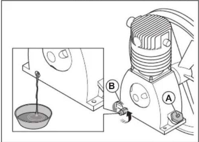
text_image
Technical diagram showing a mechanical device with labeled parts A and B, including a bucket and lever mechanism.- Let the oil drain into the container.
-
Install the oil drain plug.
-
Fill the air compressor oil tank with 1 l of oil. Refer to Technical data on page 24 for correct type of oil.
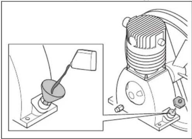
natural_image
Technical line drawing of a mechanical device with a lever and base mount (no text or symbols)
CAUTION: Do not use engine oil.
- Install the oil fill plug.
- Discard the drained oil correctly. Obey local environmental regulations.
Troubleshooting
| Problem Cause Solution | ||
| The filter cleaning system does not operate correctly. | There is no pressure or not sufficient pressure in the pressure tank. | Do a check of the pneumatic system. |
| Clean the air compressor filter. Replace if it is necessary. Refer to To clean the air compressor filter on page 12. | ||
| There is too much moisture in the pressure tank. | Use the nozzle for pressurized air to remove all moisture from the pressure tank. Refer to To drain the water from the pressure tank on page 19. | |
| The Programmable Logic Controller (PLC) does not operate correctly or the settings are incorrect. | Speak to an approved service agent. | |
| The motor is on but there is no suction. | The primary filters are dirty. | Clean the primary filters. Refer to To clean the primary filters on page 14. Replace the primary filters if it is necessary. Refer to To replace the primary filters on page 14. |
| There is a leakage in the dust collection system. | Do a check of the dust storage system for seals and leakages. Replace if it is necessary. | |
| The dust extraction hose is incorrectly installed or damaged. | Do a check of the dust extraction hose. Replace if it is necessary. | |
| The tension of the V-belts is incorrect. Do a check of the tension of the V-belts. | ||
| The indicator for phase sequence control is on. | The phases are incorrect. | Change the phase sequence. Refer to To start the product on page 10. |
| The indicator for motor failure is on. | The motor protection switch releases because of motor overload. | Make sure that you use the correct power supply. |
| Let an electrician do a check of the fault. | ||
| Dust comes out in the air from the silencer. | The primary filters are damaged or incorrectly installed. | Do a check of the primary filters. Replace if it is necessary. Refer to To replace the primary filters on page 14. |
| Unusual noises comes from the product. | There are loose screws and nuts. Tighten all screws and nuts. | |
| There is a fault with the bearings. Speak to an approved service agent. | ||
| The silencer is damaged. | Do a check of the silencer. Replace if it is necessary. | |
| The pressure in the pressure tank is less than 7 bar. | The filter for the water separator is dirty or damaged. | Clean the filter for the water separator. Replace if it is necessary. |
| The filter for the compressor is dirty or damaged. | Clean the air compressor filter. Replace if it is necessary. Refer to To clean the air compressor filter on page 12. | |
| There is a leakage in the tubes. Speak to an approved service agent. | ||
| The control valve is damaged. Speak to an approved service agent. | ||
| There is no pressure or not sufficient pressure in the pressure tank. | The pneumatic system is damaged. Do a check of the pneumatic system. | |
| The compressor filter is dirty. | Clean the air compressor filter. Replace if it is necessary. Refer to To clean the air compressor filter on page 12. | |
Transportation, storage and disposal
Transportation

WARNING: Be careful during transportation. The product is heavy and can cause injury or damage if it falls or moves during transportation.

CAUTION: Do not tow the product behind a vehicle.
- Make sure that the electrical cable and dust extraction hose are disconnected before transportation. Close the air intake when the dust extraction hose is disconnected.
- Remove the collected dust before transportation.
-
The wheels let you move the product shorter distances. For longer distances, lock the wheels and lift the product to move it or put the product on a vehicle.
-
Put some type of protection on the product during transportation. The protection keeps rain and snow away from the product.
- Make sure that there is no pressure in the pressure tank before transportation.
To move the product

WARNING: Wait until all moving parts are stationary before you move the product.

WARNING: Use protective boots with steel toe-cap and non-slip sole.
- Push or pull the product by the handle.
To move the product up and down a ramp

WARNING: Be very careful when you move the product up and down ramps. The product is heavy and there is a risk of injury if the product falls or moves too quickly.
WARNING: For ramps with a steep slope, always use a winch. Do not walk or stay below or near the product.
WARNING: Do not move the product on steep slopes. Look at the rating plate on the product for information about the maximum slope angle.
• To move the product down a ramp, operate the product forward slowly.
• To move the product up a ramp, operate the product rearward slowly.
- Do not turn the product to the left or to the right more than 45^ on a ramp.
To lift the product
WARNING: Make sure that the lifting equipment has the correct specification to lift the product safely. The type plate on the product shows the product weight.
WARNING: Do not walk or stay below or near a lifted product. Keep bystanders away from the work area.
WARNING: Do not lift a damaged product. Make sure that the lifting eyes are correctly installed and not damaged.
-
Remove the collected dust from the product.
-
Put straps through the lifting eyes and use lifting equipment to lift the product.
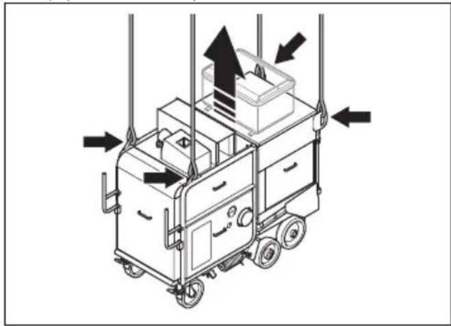
natural_image
Diagram of a mobile kitchen cart with directional arrows indicating airflow or movement (no text or symbols)- Lift the product slowly.
To attach the product to a transportation vehicle
Use the lifting eyes to attach the product to the transportation vehicle.
- Attach the tie-down straps in the lifting eyes.
- Attach and tighten the tie-down straps to the transportation vehicle.
Storage
CAUTION: Do not put the product in storage outdoors. Always keep the product indoors.
- Keep the product in a dry and frost-free area.
- Clean the product and do a complete servicing before you put the product in storage.
- Keep the product in a locked area to prevent access for children or persons that are not approved.
- Remove dust from the dust collector.
Disposal of the product
- Obey the local recycling requirements and applicable regulations.
- When the product no longer is used, send it to a Husqvarna dealer or discard it at a recycling location.
Technical data
| DC 350 EX 50 Hz | |
| Rated power, W 5500 | |
| Rated voltage, V 400 | |
| Rated frequency, Hz 50 | |
| Rated current, A 63 | |
| Cable length, m/ft. 15/50 | |
| Power cord type 4x16 mm | 2 |
| Maximum airflow, m^3/h 1250 | |
| Maximum under pressure, mbar 52 | |
| Weight, kg/lb 707/1559 | |
| Diameter dust hose connection. mm/in. 130/5 or 150/6 | |
| Oil for the air compressor BOGE Syprem 8000 K compres- sor oil | |
Note: If your product requires an electrical specification that is not in the table, speak to a Husqvarna service agent for more information.
Noise emissions
| Sound power level, LWA dB (A) ^1 | 101 |
| Sound pressure level at the operator's ear, LP dB (A) ^2 | 85 |
| ^1 Sound power leveldetermined according to EN ISO 3747. Measured on concrete surface. Uncertainty Kwa 2.5 dB | |
| ^2 Sound pressure level determined according to EN ISO 11202. Measured on concrete surface. Uncertainty Kpa 2.5 dB | |
Noise and vibration declaration statement
These declared values were obtained by laboratory type testing in accordance with the stated directive or standards and are suitable for comparison with the declared values of other products tested in accordance with the same directive or standards. These declared
values are not suitable for use in risk assessments and values measured in individual work places may be higher. The actual exposure values and risk of harm experienced by an individual user are unique and depend upon the way the user works, in what material the product is used, as well as upon the exposure time and the physical condition of the user, and the condition of the product.
Extension cables
| Cable length Cross section | ||||
| ≤ 16 A ≤ 32 | A ≤ 63 A ≤ 125 A | |||
| Calculated at a pre-fuse GG ^3 : 16 amp 32 amp 63 | amp 125 amp | |||
| >20m 1.5 mm | ^2 | 2.5 mm ^2 | 10 mm ^2 | 25 mm ^2 |
| 20m >50m 2.5 mm | ^2 | 4 mm ^2 | 10 mm ^2 | 25 mm ^2 |
| 50m >75m 4 mm | ^2 | 6 mm ^2 | 16 mm ^2 | 35 mm ^2 |
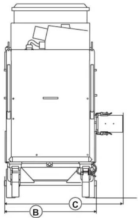
Product dimensions
natural_image
Technical line drawing of a mechanical device with labeled dimensions B and C (no text or symbols beyond labels)
natural_image
Technical line drawing of a mechanical device with labeled dimensions A and D (no text or symbols beyond labels)| A Length, mm/in. 1832/72 | ||
| B Width with out dust collector hose adapter, mm/in. 793/31 | ||
| C Widht with dust collector hose adapter, mm/in. 1018/40 | ||
| D Height, mm/in. 1680/66 |
Accessories
| Available accessory Item number | |
| Primary filter cartridge M-class 534 33 49-01 |
Declaration of Conformity
EU Declaration of Conformity
We, Husqvarna AB, SE-561 82 Huskvarna, Sweden, tel: +46-36-146500, declare on our sole responsibility that the product:
| Description Dust collector | |
| Brand Husqvarna | |
| Type/Model DC 350 EX | |
| Identification Serial numbers dating from 2025 and onwards | |
complies fully with the following EU directives and regulations:
| Directive/Regulation Description | |
| 2006/42/EC "relating to machinery" | |
| 2014/30/EU "relating to electromagnetic compatibility" |
and that the following standards and/or technical specifications are applied;
EN ISO 12100:2010, EN 60204-1:2006
Partille, 2025-03-06
text_image
Christian HyberChristian Nyberg
Senior Director, R&D Heavy Equipment
Husqvarna AB, Construction Division
Responsible for technical documentation

UK Importer:
Husqvarna UK Ltd
Preston Road, Co. Durham
DL5 6UP
Inhalt
Einleitung.... 28
Sicherheit....31
Betrieb.... 36
Wartung.... 39
Fehlersuche.... 49
text_image
Technical diagram of a mechanical device with numbered components and exploded view, including labeled parts 1 through 15.text_image
Husqvarna Husqvarna Identity No. (HID) Serial No. 13 Product No. 12 11 10 HUSQVARNA AB, SE-861 82 HUSKVARNA, SWEDEN 5 6 7 8 9natural_image
Technical line drawing of a mechanical clamp or bracket assembly with no visible text or symbolstext_image
Technical diagram showing mechanical assembly with lock and lock switch mechanism, including directional arrows and component placement.natural_image
Diagram of a mechanical device with a rotating lever and clamping mechanism (no text or symbols)natural_image
Technical line drawing of a mechanical device with mounting brackets and a close-up inset showing internal components (no text or symbols)natural_image
Technical line drawing of a two-part mechanical device with a pull-up view showing the front panel and side panel (no text or symbols)natural_image
Technical illustration of a mechanical cart with a puller and attached housing, showing motion arrows (no text or symbols)
natural_image
Technical line drawing of a mechanical device with a zoomed-in view showing internal components (no text or symbols)text_image
Technical diagram showing a mechanical assembly with labeled components and a magnified inset of a cylindrical component with a dial indicator.natural_image
Technical illustration of a vehicle's wheel assembly with a magnified inset showing the wheel being inserted (no text or symbols present)natural_image
Technical line drawing of a kitchen appliance with labeled parts (no text or symbols present)natural_image
Technical line drawing of a vehicle chassis with wheels and a panel, showing internal components and motion arrows (no text or symbols)natural_image
Technical illustration of a mechanical assembly with exploded view and close-up detail (no text or symbols)natural_image
Technical line drawing of a mechanical assembly showing a motor and a cylindrical component with a downward arrow indicating motion (no text or symbols)natural_image
Technical line drawing of a mechanical assembly with no visible text or symbolsnatural_image
Technical diagram of a mechanical assembly with a zoomed-in inset showing a component detail (no text or symbols present)natural_image
Mechanical assembly diagram showing a pulley system with a cylindrical component and wheels (no text or symbols)natural_image
Technical line drawing of a mechanical device with a directional arrow indicating movement or force (no text or symbols present)text_image
Technical diagram of a mechanical pulley system with labeled components A and Btext_image
Diagram of a belt drive system with pulleys and belt, labeled point Anatural_image
Technical line drawing of a mechanical device with a directional arrow indicating motion (no text or symbols present)natural_image
Technical line drawing of a mechanical device with wheels and a panel, showing internal components without any text or symbols.text_image
Technical diagram of a mechanical assembly with labeled components A, B, and C, showing exploded and assembled views.natural_image
Technical line drawing of a mechanical device with a directional arrow indicating motion (no text or symbols present)natural_image
Technical line drawing of a mechanical device with wheels and a panel, showing internal components and a directional arrow (no text or symbols)text_image
Technical diagram of a mechanical device with labeled components A, B, and C, showing internal components and assembly views.natural_image
Technical illustration of a mechanical device with a directional arrow indicating motion, showing internal components and no visible text or symbols.natural_image
Technical line drawing of a mechanical device with wheels and a panel, showing internal components without any text or symbols.natural_image
Technical line drawing of a mechanical device with wheels and a panel, showing internal components and alignment (no text or symbols)text_image
Technical diagram of a mechanical device with labeled components A, B, and C, showing internal components and assembly details.text_image
Technical diagram of a mechanical device with labeled components A, B, and C, showing internal components and external view.natural_image
Technical line drawing of a vehicle chassis with wheels and a door panel, showing mechanical components without any text or symbols.natural_image
Technical line drawing of a mechanical assembly with labeled components (no text or symbols present)text_image
Technical diagram of a mechanical device with labeled component B and directional arrow indicating assembly or movement.natural_image
Technical line drawing of a vehicle chassis with attached components and a hand gesture showing motion (no text or symbols)natural_image
Technical line drawing of a mechanical device with wheels and a panel, showing no text or symbolsnatural_image
Technical line drawings of industrial equipment components, including a motor and a heat exchanger (no text or symbols)natural_image
Technical line drawing of a mechanical device with wheels and a panel, showing internal components and alignment lines (no text or symbols)text_image
Technical diagram showing a mechanical device with labeled parts A and B, including a bucket and a rod inserted into a bowl.natural_image
Technical line drawing of a mechanical device with a lever and housing (no text or symbols)Fehlersuche
natural_image
Technical line drawing of a mobile cart with directional arrows indicating movement or force (no text or symbols present)natural_image
Technical line drawing of a mechanical device with labeled dimensions B and C (no text or symbols beyond labels)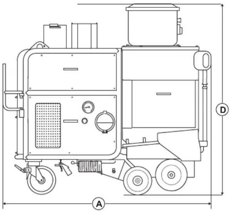
natural_image
Technical line drawing of a mechanical device with labeled dimensions A and D (no text or symbols beyond labels)Senior Director, R&D Heavy Equipment
Husqvarna AB, Construction Division
Preston Road, Co. Durham
DL5 6UP
Sommaire
Introduction.... 56
Sécurité....59
Utilisation.... 63
Entretien.... 66
text_image
Technical diagram of a mechanical device with numbered components and exploded view, including labeled parts 1 through 15.natural_image
Technical line drawing of a mechanical clamp or bracket assembly with no visible text or symbolstext_image
Technical diagram showing mechanical assembly with lock mechanism and directional arrows indicating motion or force directionsnatural_image
Technical diagram of a mechanical device with a rotating lever and clamping mechanism (no text or symbols)natural_image
Technical line drawing of a wheeled cart with mechanical components and a close-up inset showing a component detail (no text or symbols)natural_image
Technical line drawing of a two-door electrical cabinet with a pull-up of its side panel (no text or symbols)natural_image
Technical illustration of a mechanical device with a pull-up of a wheelbarrow and a close-up view of the component (no text or symbols present)
natural_image
Technical line drawing of a mechanical device with a zoomed-in view showing internal components (no text or symbols)text_image
Technical diagram showing a mechanical assembly with labeled components and directional arrows indicating motion or movement.natural_image
Technical line drawing of a mechanical device with a close-up inset showing a component being inserted into a circular component (no text or symbols present)natural_image
Technical illustration of a mechanical device with two views: top shows a meshed plate, bottom shows a cooking pot (no text or symbols)natural_image
Technical line drawing of a vehicle chassis with wheels and a door panel, showing mechanical components without any text or symbols.natural_image
Technical illustration of a mechanical assembly with exploded view and close-up detail (no text or symbols)natural_image
Technical illustration of a mechanical assembly showing a motor and a cylindrical component with a downward arrow indicating motion (no text or symbols present)natural_image
Technical line drawing of a mechanical assembly with no visible text or symbolsnatural_image
Technical line drawing of a mechanical assembly with a zoomed-in inset showing a component detail (no text or symbols present)natural_image
Mechanical assembly diagram showing a pulley system with a cylindrical component and wheels (no text or symbols)natural_image
Technical line drawing of a mechanical device with a directional arrow indicating motion (no text or symbols present)text_image
Technical diagram of a mechanical device with labeled components A and B, showing pulley and wheel assembly.text_image
Diagram of a belt drive system with pulleys and belt, labeled point Anatural_image
Technical line drawing of a mechanical device with a directional arrow indicating left motion (no text or symbols present)natural_image
Technical line drawing of a mechanical device with wheels and a panel, showing internal components without any text or symbols.text_image
Technical diagram of a mechanical assembly with labeled components A, B, and C, showing internal components and external view.natural_image
Technical illustration of a mechanical device with a directional arrow indicating motion (no text or symbols present)natural_image
Technical line drawing of a mechanical device with wheels and a panel, showing no text or symbolstext_image
Technical diagram of a mechanical device with labeled components A, B, and C, including a detailed view of the wheel assembly.natural_image
Technical line drawing of a mechanical device with a directional arrow indicating motion (no text or symbols present)natural_image
Technical line drawing of a mechanical device with wheels and a door panel, showing internal components without any text or symbols.natural_image
Technical line drawing of a mechanical device with wheels and a panel, showing internal components and alignment (no text or symbols)text_image
Technical diagram of a mechanical device with labeled components A, B, and C, showing internal components and assembly views.text_image
Technical diagram of a mechanical device with labeled components A, B, and C, showing internal components and assembly.natural_image
Technical line drawing of a vehicle chassis with wheels and a door panel, showing internal components without any text or symbols.natural_image
Technical line drawing of a mechanical assembly with labeled components (no text or symbols present)natural_image
Technical diagram of a mechanical device with an inset showing a component labeled B (no text or symbols present)natural_image
Technical line drawing of a vehicle chassis with attached components and a hand gesture indicator (no text or symbols)natural_image
Technical line drawing of a mechanical device with wheels and a panel, showing no text or symbolsnatural_image
Technical line drawings of industrial equipment components, including a motor and a heat exchanger (no text or symbols)natural_image
Technical line drawing of a mechanical device with wheels and a panel, showing internal components and alignment lines (no text or symbols)text_image
Technical diagram showing a mechanical device with labeled parts A and B, including a bucket and lever mechanism.natural_image
Technical line drawing of a mechanical device with a lever and housing, shown from two different angles (no text or symbols present)
natural_image
Diagram of a mobile cart with directional arrows indicating movement or force, no text or symbols presentnatural_image
Technical line drawing of a mechanical device with labeled dimensions B and C (no text or symbols beyond labels)
natural_image
Technical line drawing of a mechanical device with labeled dimensions A and D (no text or symbols beyond labels)Husqvarna AB, division Construction
Responsable de la documentation technique

UK Importer:
Husqvarna UK Ltd
Preston Road, Co. Durham
DL5 6UP
Inhoud
Inleiding....84
Veiligheid.... 87
Werking....91
Onderhoud....94
Probleemoplossing.... 104
text_image
Technical diagram of a portable industrial machine with numbered components and exploded viewtext_image
Husqvarna Husqvarna Identity No. (HID) Serial No. 13 Product No. 12 11 10 L 21 3 4 5 6 7 8 9 HUSQVARNA AB, SE-561 82 HUSKVARNA, SWEDENnatural_image
Technical line drawing of a mechanical clamp or bracket assembly with no visible text or symbolstext_image
Technical diagram showing mechanical assembly with lock and locking mechanism, including magnified views of key componentsnatural_image
Diagram of a mechanical device with a rotating lever and clamping mechanism (no text or symbols)natural_image
Technical line drawing of a wheeled cart with mechanical components and directional arrows indicating motion (no text or symbols)natural_image
Technical line drawing of a two-door electrical cabinet with a pull-up of its side panel (no text or symbols)natural_image
Technical illustration of a mechanical device with a pull-up of a wheelbarrow and a close-up view of the component (no text or symbols present)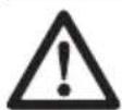
natural_image
Technical line drawing of a vehicle's internal components and a hand tool, showing assembly and insertion (no text or symbols)text_image
Technical diagram showing a mechanical assembly with labeled components and directional arrows indicating motion or movement.natural_image
Technical diagram of a vehicle's internal components and a close-up of a mechanical component with motion arrows (no text or symbols)text_image
Technical diagram showing components of a mechanical device with labeled parts A and B, including a meshed lid and a motor cart.natural_image
Technical line drawing of a vehicle chassis with wheels and a door panel, showing internal components without any text or symbols.natural_image
Technical line drawing of a mechanical assembly with exploded view and close-up detail (no text or symbols)natural_image
Technical illustration of a mechanical assembly showing a motor and a cylindrical component with a downward arrow indicating motion (no text or symbols present)natural_image
Technical line drawing of a mechanical assembly with no visible text or symbolsWAARSCHUWING: Sluit de
natural_image
Technical line drawing of a mechanical assembly with a zoomed-in inset showing internal components (no text or symbols)natural_image
Mechanical assembly diagram showing a cart with wheels and a cylindrical component under load (no text or symbols)natural_image
Technical line drawing of a mechanical device with a directional arrow indicating flow or movement (no text or symbols present)text_image
Technical diagram of a mechanical pulley system with labeled components A and Bnatural_image
Diagram of a belt drive system with pulleys and belt, showing center point A (no text or labels)natural_image
Technical line drawing of a mechanical device with a directional arrow indicating motion (no text or symbols present)natural_image
Technical line drawing of a mechanical device with wheels and a panel, showing internal components without any text or symbols.- Draai de 4 bouten (A) los.
text_image
Technical diagram of a mechanical assembly with labeled parts A, B, and C, showing internal components and external view.natural_image
Technical illustration of a mechanical device with a directional arrow indicating motion (no text or symbols present)natural_image
Technical line drawing of a mechanical device with wheels and a panel, showing no text or symbols- Draai de 4 bouten (A) los.
text_image
Technical diagram of a mechanical device with labeled components A, B, and C, showing internal components and external view.natural_image
Technical line drawing of a mechanical device with a directional arrow indicating motion (no text or symbols present)natural_image
Technical line drawing of a mechanical device with wheels and a panel, showing internal components without any text or symbols.natural_image
Technical line drawing of a mechanical device with wheels and a panel, showing no text or symbolstext_image
Technical diagram of a mechanical device with labeled components A, B, and C, showing internal components and assembly details.text_image
Technical diagram of a mechanical device with labeled components A, B, and C, showing internal components and assembly details.natural_image
Technical line drawing of a mechanical assembly with wheels and a panel, showing no text or symbolsnatural_image
Technical line drawing of a mechanical assembly with labeled components (no text or symbols present)text_image
Technical diagram showing a mechanical assembly with labeled component B and directional arrownatural_image
Technical line drawing of a mechanical device with a close-up inset showing a hand holding a tool (no text or symbols present)natural_image
Technical line drawing of a mechanical device with wheels and a panel, showing no text or symbolsnatural_image
Technical line drawing of industrial equipment including a cart and a heat exchanger (no text or symbols)natural_image
Technical line drawing of a mechanical device with wheels and a panel, showing no text or symbolstext_image
Technical diagram showing a mechanical device with labeled parts A and B, including a bucket and a rod inserted into a bowl.natural_image
Technical line drawing of a mechanical device with a lever and base mount (no text or symbols)
natural_image
Isometric line drawing of a mobile kitchen cart with directional arrows indicating movement or force (no text or symbols)natural_image
Technical line drawing of a mechanical device with labeled dimensions B and C (no text or symbols beyond labels)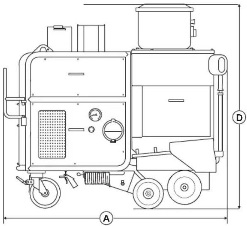
natural_image
Technical line drawing of a mechanical device with labeled dimensions A and D (no text or symbols beyond labels)Senior Director, R&D Heavy Equipment
Husqvarna AB, Construction Division
Preston Road, Co. Durham
DL5 6UP
Husqvarna®
www.husqvarnaconstruction.com
Original instructions
Originalanweisungen