
Gloria HPS-2.5-1200 - Energy storage battery HAIER - Free user manual and instructions
Find the device manual for free Gloria HPS-2.5-1200 HAIER in PDF.

User questions about Gloria HPS-2.5-1200 HAIER
0 question about this device. Answer the ones you know or ask your own.
Ask a new question about this device
Download the instructions for your Energy storage battery in PDF format for free! Find your manual Gloria HPS-2.5-1200 - HAIER and take your electronic device back in hand. On this page are published all the documents necessary for the use of your device. Gloria HPS-2.5-1200 by HAIER.
USER MANUAL Gloria HPS-2.5-1200 HAIER
official website NAHUI Nahui Intelligent APP
GLORIA
HPS-2.5-(350\~2400)
Energy storage controller system
QingDao Nahui Intelligent Technologies Co., Ltd.
Room 205-2, Building 4, No. 7 Keji 1st Road, Aoshanwei Street Office, Jimo District, Qingdao City, Shandong Province, P.R. China
service-nahui@haier-europe.com
www.nahui-newenergy.com
If the product size and parameters are changed,
the latest information of our company shall
prevail without prior notice.
2024 10.15 A1.0

Multilingual manual QR code

Scan the QR code to download the user manual in other languages

natural_image
White Haier air purifier device with control panel and external ports (no visible text or symbols on body)EN
Installation Guide 01-08
- Important Note 01
- Packing Details 02
- Product Size 02
- Product Introduction 03
- Installation Requirements 03
- Installation Steps 04
- System Connection 06
- Check Before Power On 06
- Test Operation Process 07
- App Connection 07
- Indicator Light Definition 08
DE
- This document will be updated from time to time due to product upgrade or other reasons. Under no circumstances may this document replace the User Manual and the safety instructions on the product.
- Before any operation, please read the User Manual and relevant standards and specifications carefully, which can be obtained on the website of www.nahui-newenergy.com.
- Please read the manual completely for all equipment operations, master the safety matters related to operation, and be familiar with local standards and relevant safety specifications of electrical systems.
- Please use insulating tools and wear personal protective equipment when operating.
- Failure to follow the requirements of this document and the User Manual for equipment related operations may cause casualties or equipment damage, and Haier will not assume any responsibility.
02/Packing Details
| Name NameQuantity | Quantity | ||
| Energy storage controller system | 1 | Expansion bolt assembly M8*60 | 2 |
| Wall bracket | 1 | Quick installation guide | 1 |
| 3m PV extension cable | 2 | Installing positioning paper | 1 |
| 1.5m AC Cable | 1 | Open-end wrench | 1 |
| Smart plug | 1 | Meter or Smart Meter | Optional |
Warning Label On Energy Storage Controller System
 | All external power connections must be disconnected before the maintenance operation of the energy storage controller system. |  | There is a high voltage after the energy storage is powered on, and there is still a residual voltage after the energy storage is powered off, which needs to be discharged to safe voltage. |
| [YCAS] | The temperature of the hot surface of the equipment may be higher than 60°C, so be careful of burns. |  | Read the instructions before operating the energy storage controller system. |
 | High-voltage danger, it is forbidden to connect and disconnect wires, disassemble the chassis and replace devices under live conditions. |  | Protective grounding. |
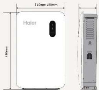
03/Product Size
HPS-2.5-350, HPS-2.5-400,
HPS-2.5-600, HPS-2.5-800,
HPS-2.5-1000, HPS-2.5-1200,
HPS-2.5-1600, HPS-2.5-2000,
HPS-2.5-2400
text_image
510mm 190mm Haier 810mm04/Product Introduction
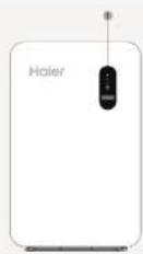
(1) Display screen
(2) Photovoltaic input positive port
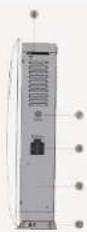
(3) Photovoltaic input negative port
(6) Wifi antenna
(10) External grounding point(9) Product nameplate
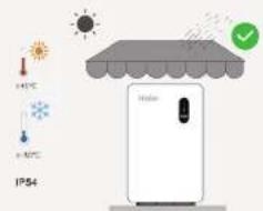
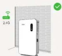
05/Installation Requirements
Be suitable for indoor, living room, balcony, garden, sunshade and other home places.
text_image
IP54 + 10°C - 10°C + 20°C + 20°C + 20°C + 20°C + 20°C + 20°C + 20°C + 20°CEnsure the coverage of Wifi network signals.
text_image
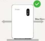
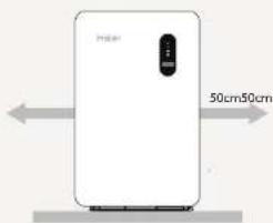
2.4GWhen installing, 50cm should be reserved in the left and right space to ensure the requirements of heat dissipation and safety isolation during installation.sunshade and other home places.
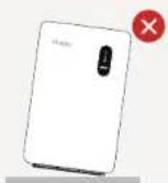
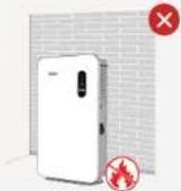
No tilt mounting. Ensure that there are no inflammable,
explosive and other dangerous goods around when installing the product.
06/Installation Steps
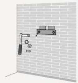
- Make sure to avoid the water and electricity lines in the wall before drilling to avoid danger! - Place the hanging plate vertically on the wall. It is recommended to select the hole position shown in the figure, mark the drilling position and drill the hole, and keep the drilling depth is greater than 60mm.
Step 1
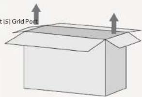
Firstly, take the product out of the box.
text_image
(5) Grid PortStep 3
According to the positioning paper template, place it on the wall, mark the installation hole position, and punch holes with an impact drill.

text_image
Hole spacing: 160mmStep 2
When installing, it is necessary to ensure that the product is at least 50cm away from both sides of the wall, and heat dissipation is ensured. It should be installed in a waterproof, dry and ventilated environment.
text_image
50cm50cmStep 4
Use the vacuum cleaner to clean the dust in the hole, take out the expansion screw, plug the expansion nut into the hole, and use a rubber hammer to completely plug the expansion nut into the hole.
natural_image
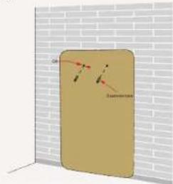
3D diagram of a rectangular object with internal lines and a label 'Supervision' against a brick wall background (no readable text or symbols)Step 5
Install the wall bracket.
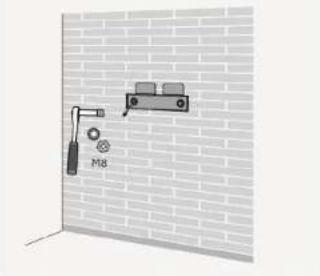
natural_image
Diagram of a wall-mounted pulley system mounted on a brick wall, no text or symbols presentStep 6
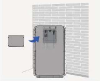
Remove the four screws of the backboard on the back of the product, and be careful to save the screws.
natural_image
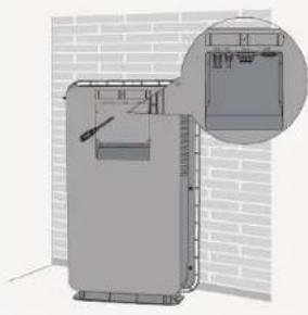
3D architectural rendering of a fire extinguisher with a close-up inset showing internal components (no text or symbols)Step 7
Connect the prepared PV+, PV- and AC wires to the corresponding positions of the product, ensure that the connection is undamaged, and then reinstall the backplane.
natural_image
Diagram of a door with a blue arrow pointing to the interior panel, set against a brick wall background (no text or symbols)Step 8
Align the mounting holes on the back of the product and insert them into the fixing bracket from top to bottom to ensure that the product can be placed on the ground, that is, the product is fixed and installed.
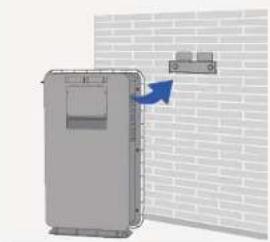
natural_image
3D diagram of a door mechanism with a blue arrow pointing to a wall-mounted device (no text or symbols present)07/System Connection
- Before connecting to the power grid, first ensure that the grid voltage and frequency meet the requirements of the energy storage controller system. For detailed parameters, please refer to the "Technical Parameters" in the User Manual; otherwise, it is needed to contact the power company to solve it.
- Verify your country requirements if you need to obtain the access permission of the local power company to connect the energy storage controller system to the power grid;
- The power strip connected between EPS output port and Grid needs to be purchased by yourself.
- Before connecting the PV modules, to avoid any damage not covered by the warranty, please verify the configuration chosen respect the main parameters. Verify the power (Pmax) installed does not exceed 1200W, the sum of the current (Imp) of each parallel configured panel is less than 28A, and the sum of the voltage (Voc) of each serial configured panel is less than 150V.
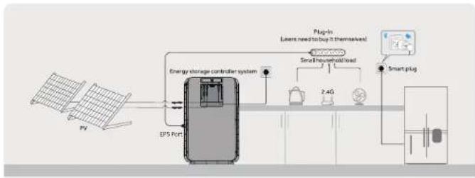
flowchart
graph LR
    A["PV"] --> B["Energy storage controller system"]
    B --> C["2.4G"]
    C --> D["Smart plug-in (Latent need to buy it themselves)"]
    D --> E["Small household load"]
    E --> F["Plug-in (Latent need to buy it themselves)"]
    F --> G["Smart plug"]
    G --> H["Ground"]
    B --> I["EPS Port"]
08/Check Before Power On
Inspection items Acceptance standard
| Equipment installed in place | The equipment is installed correctly, firmly and reliably. |
| Reasonable cable layout | The cable layout is reasonable and meets the user's requirements. |
| Binding tape | Tie the tape evenly, and leave no sharp corners at the cut. |
| Switch disconnected | The product start switch is in the off state, and the LED and LCD are in the off state. |
| Cable connected in place | DC, AC and Comm connection is correct, firm and reliable. |
| Backplate installation | Backboard is installed in and fixed with the 4 screws |
| The installation environment meets the requirements | The installation space is reasonable, the environment is clean and tidy, and there is no construction residue. |
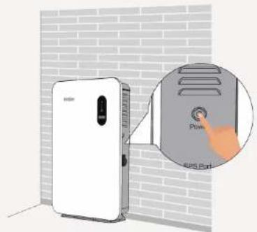
09/Test Operation Process
Step 1: Check that the external wiring harness is connected normally;
Step 2: When the button is in ON state, the light is green;
Step 3: When powered on for the first time, Observe whether the LCD screen are on and LED indicator is red.
Step 4: Perform the first commissioning using the dedicated app Nahui Intelligent.
text_image
Diagram showing a white air purifier connected to a wall-mounted device with a hand pointing to the screen labeled 'Power & 2.0V'.10/App Connection
- Scan the QR code or enter the link to download the APP to the mobile phone, and register/log in according to the operation instructions;
- APP Android / iOS download address:
https://server-hr.shuoxd.com:8443/resources/od m/download-hr.html
* For more detailed contents of the App, please refer to the Nahui Intelligent User Manual.


Nahui Intelligent APP User Manual
11/Indicator Light Definition
- LED light + LCD screen is used as the human-machine interaction interface, and the LED indicator on the front panel of the inverter can indicate the current working state of the inverter.
| Indicator | Color | Explanation | |
| [028Z] | Blue is always on | Discharging | |
| Blue is flicking | Charging | ||
| [22XT] | Green is always on The system is upgrading | ||
 | Red is always on | System failure or alarm | |
| LCD indicator | Fault code |
| Please refer to the User manual |
Note:
- If the test operation fails, please refer to the "Fault Code" in the User Manual.
- Please refer to "Indicator Definition" in the User Manual for the indicator definition.
natural_image
Simple line drawing of an open box with two upward arrows indicating top and bottom (no text or symbols)Schritt 2
text_image
Procam 50cm90cmSchritt 3
natural_image
Simple 3D illustration of a beige rectangular object with a red diagonal line and small symbols, set against a white brick wall (no text or labels)Schritt 5
natural_image
Diagram of a mechanical device labeled M8 mounted on a brick wall, no text or symbols presentSchritt 6
natural_image
3D rendering of a mechanical device with a close-up inset showing internal components (no text or symbols visible)Schritt 7
natural_image
Diagram of a mechanical device with a blue arrow indicating direction, set against a brick wall background (no text or symbols)Schritt 8
natural_image
Diagram of a door-mounted device mounted on a brick wall, with a blue arrow indicating rotation (no text or symbols present)text_image
Diagram showing a white electronic device connected to a wall-mounted control panel with a magnified inset highlighting the '4KG Pull' button.10/App-Verbindung
natural_image
Simple line drawing of an open box with two upward arrows indicating top and bottom (no text or symbols)Fase 2
text_image
H269 50cm50cmFase 3
natural_image
Illustration of a beige door with red markings against a brick wall background (no text or symbols)
natural_image
Diagram of a wall-mounted device mounted on a brick wall, with no visible text or symbolsFase 6
natural_image
3D architectural rendering of a building interior with brick walls and a close-up inset showing internal components (no text or symbols)Fase 7
natural_image
Exterior view of a gray electrical enclosure with a blue arrow pointing to its side panel, against a brick wall background (no text or symbols)Fase 8
natural_image
Diagram of a door with a blue arrow pointing to a wall-mounted cabinet (no text or symbols present)
flowchart
graph LR
    A["PV"] --> B["Internal control on installed range"]
    B --> C["Power supply unit"]
    C --> D["DC/DC"]
    D --> E["Ground"]

text_image
Diagram showing a white air purifier device with a magnified inset highlighting the 'Pump' button and 'EOS port' label.natural_image
Simple line drawing of an open box with two upward arrows indicating growth (no text or symbols)Étape 3
natural_image
Simple 3D diagram of a rectangular panel with a small red line and label 'i' on its side, set against a brick wall background (no text or symbols)Étape 5
Installez le support mural.
natural_image
Diagram of a wall-mounted device mounted on a brick wall, labeled 'M8' (no text or symbols beyond label)natural_image
3D rendering of a mechanical device with a close-up inset showing internal components (no text or symbols visible)natural_image
Diagram showing a device with a blue arrow pointing to a component, set against a brick wall background (no text or symbols)Étape 8
natural_image
3D diagram of a door with a blue arrow pointing to a wall-mounted cabinet (no text or symbols present)05/Installation Requirements
natural_image
Simple line drawing of an open box with two upward arrows indicating growth (no text or symbols)Paso 2
natural_image
Illustration of a beige rectangular object with red arrows pointing to it, set against a brick wall (no text or symbols)natural_image
Diagram of a wall-mounted device mounted on a brick wall, showing a bracket and hanging weights (no text or symbols)natural_image
3D rendering of a mechanical device with a close-up inset showing internal components (no text or symbols visible)natural_image
Diagram of a door with a blue arrow pointing to the front panel, set against a brick wall background (no text or symbols)Paso 8


