AW12TE1VHA - Air Conditioning HAIER - Free user manual and instructions
Find the device manual for free AW12TE1VHA HAIER in PDF.

User questions about AW12TE1VHA HAIER
0 question about this device. Answer the ones you know or ask your own.
Ask a new question about this device
Download the instructions for your Air Conditioning in PDF format for free! Find your manual AW12TE1VHA - HAIER and take your electronic device back in hand. On this page are published all the documents necessary for the use of your device. AW12TE1VHA by HAIER.
USER MANUAL AW12TE1VHA HAIER
natural_image
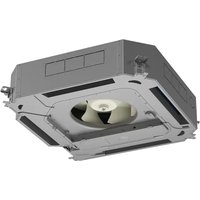
Exterior view of a Haier air conditioner unit with fan blades (no text or symbols on the device itself)Tempo SERIES
TABLE OF CONTENTS
UNIT DIMENSIONS .... 4
CLEARANCES....6
SYSTEM 7
Part 1: General....7
Part 2: Performance and Operating Range ....7
Part 3: Installation Requirements .... 11
Part 4: Electrical Requirements....11
OUTDOOR UNIT....12
Part 1: General....12
Part 2: Installation 12
Part 3: Components ...... 12
WALL MOUNT INDOOR UNIT....13
Part 1: General....13
Part 2: Installation Requirements .... 13
Part 3: Electrical Requirements .... 13
Part 4: Components ...... 14
CONTROLS AND ACCESSORIES....15
Part 1: YR-HG Wireless Control....15
Part 2: Wired Controllers .... 15
Part 3: QAWF01A WiFi Adapter 16
Part 4: WK-B Interface Kit 16
LIMITED WARRANTY 17
UNIT DIMENSIONS
1U09TE1VHA / AW09TE1VHA
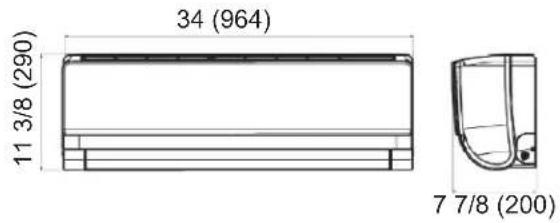
1U12TE1VHA / AW12TE1VHA
text_image
34 (964) 11 3/8 (290) 7 7/8 (200)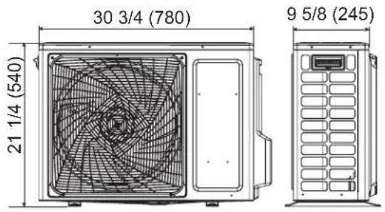
text_image
30 3/4 (780) 21 1/4 (540) 9 5/8 (245)1U09TE2VHA / AW09TE2VHA
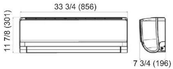
1U12TE2VHA / AW12TE2VHA
text_image
33 3/4 (856) 11 7/8 (301) 7 3/4 (196)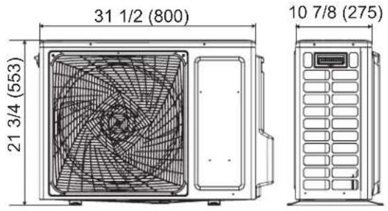
text_image
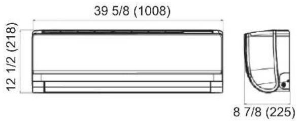
31 1/2 (800) 21 3/4 (553) 10 7/8 (275)1U18TE2VHA / AW18TE2VHA
text_image
39 5/8 (1008) 12 1/2 (218) 8 7/8 (225)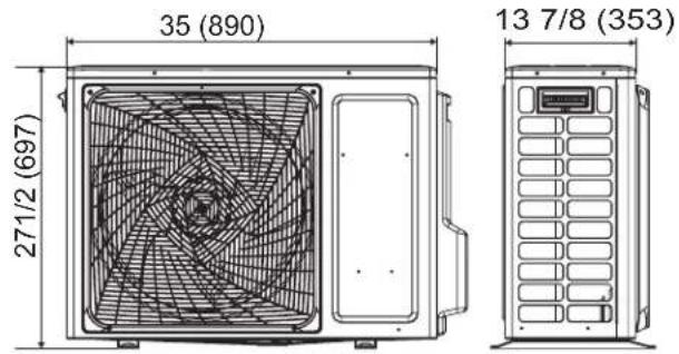
text_image
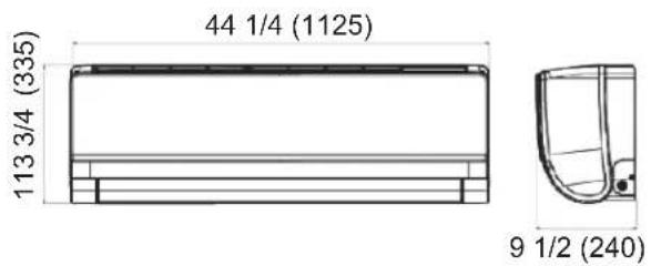
35 (890) 271/2 (697) 13 7/8 (353)1U24TE2VHA / AW24TE2VHA
text_image
44 1/4 (1125) 113 3/4 (335) 9 1/2 (240)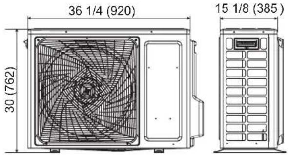
text_image
36 1/4 (920) 30 (762) 15 1/8 (385)1U24TL2HFA / AW24TL2HFA, 1U3036TL2HFA / AW30TL2HFA, 1U3036TL2HFA / AW36TL2HFA
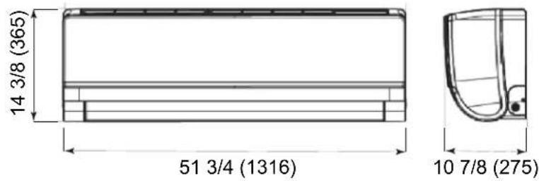
text_image
14 3/8 (365) 51 3/4 (1316) 10 7/8 (275)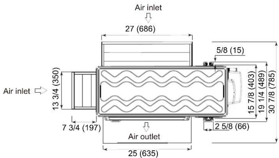
text_image
Air inlet 27 (686) 5/8 (15) 13 3/4 (350) 15 7/8 (403) 19 1/4 (489) 30 7/8 (785) 7 3/4 (197) 2 5/8 (66) Air outlet 25 (635)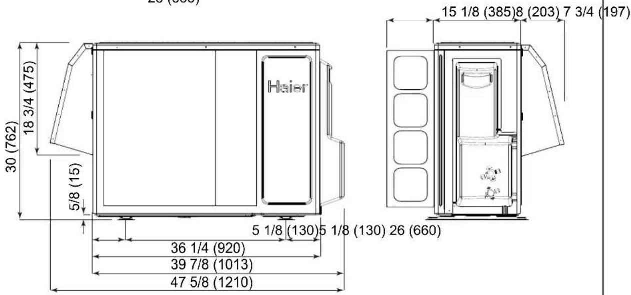
text_image
26 (800) 15 1/8 (385)8 (203) 7 3/4 (197) 18 3/4 (475) 30 (762) 5/8 (15) 5 1/8 (130) 5 1/8 (130) 26 (660) 36 1/4 (920) 39 7/8 (1013) 47 5/8 (1210)MINIMUM CLEARANCES
(Appearance may vary)
This picture is for reference only, as your product may look different. Read your manual before installation. Explain the operation of the unit to the user according to this manual.
text_image
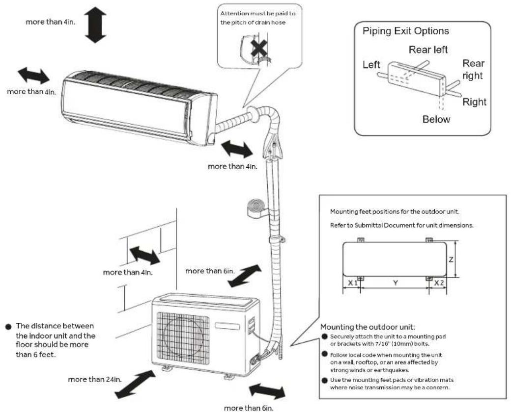
more than 4in. more than 4in. more than 4in. more than 6in. more than 24in. more than 6in. Attention must be paid to the pitch of drain hose. Piping Exit Options Rear left Left Rear right Right Below Mounting feet positions for the outdoor unit. Refer to Submittal Document for unit dimensions. Z X1 Y X2 ● The distance between the indoor unit and the floor should be more than 6 feet. Mounting the outdoor unit: ● Securely attach the unit to a mounting pad or brackets with 7/16" (10mm) bolts. ● Follow local code when mounting the unit on a wall, rooftop, or an area affected by strong winds or earthquakes. ● Use the mounting feet pads or vibration mats where noise transmission may be a concern.(1) Single-unit installation (unit: in. (mm.))
text_image
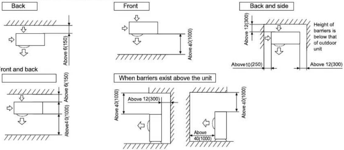
Back Front Back and side Height of barriers is below that of outdoor unit Above 12(300) Above 12(300) Above 40(1000) Above 40(1000) Above 6(150) Above 6(150) Above 10(250) Above 40(1000) Above 40(1000) Above 6(150) Front and back When barriers exist above the unit Above 12(300) Above 40(1000) Above 40(1000)Part 1: General
1.1 Description
A. The Haier Tempo heat pump air conditioner shall be a variable capacity, mini-split type system comprised of a single outdoor and a single wall-mounted indoor unit.
1.2 Toxicity
A. The heat pump system shall participate in RoHS compliance and listed in the directory.
Part 2: Performance and Operating Range
2.1 Operating Range
A. 1U09TE1VHA, 1U12TE1VHA, 1U09TE2VHA, 1U12TE2VHA, 1U18TE2VHA, 1U24TE2VHA, 1U24TL2HFA, and 1U3036TL2HFA heat pump models shall provide cooling at a temperature range of 23^115^ (-5°\~46°C) without a wind baffle.
B. 1U09TE1VHA, 1U12TE1VHA, 1U09TE2VHA, 1U12TE2VHA, 1U18TE2VHA and 1U24TE2VHA heat pump models shall provide cooling at a temperature range of 14^ 115^ (-10°\~46°C) with a front wind baffle.
C. 1U24TL2HFA and 1U3036TL2HFA heat pump models shall provide cooling at a temperature range of -4^ 115^ (-20^ 46^) with a front wind baffle.
D. 1U24TL2HFA and 1U3036TL2HFA heat pump models shall provide cooling at a temperature range of -40^ 115^ ( -40^ 46^ ) with a front, side and rear wind baffle.
2.2 Performance
The system shall perform within the specified operating window found on the following table.
A. Cooling performance rating shall be verified following AHRI 210/240 standards of 80°F DB/67°F WB (27°/19°C) indoor temperature and 95°F DB/75°F WB (35°/24°C) outdoor temperature.
B. Heating performance rating shall be verified following AHRI 210/240 standards of 70°F DB/60°F WB (21°/16°C) indoor temperature and 47°F DB/43°F WB (8°/6°C) outdoor temperature.
SYSTEM
Specifications:
Compressor Type: DC Inverter Driven Rotary
Voltage/Cycle/Phase: 115/60/1:09TE1, 12TE1
| Model Name | System 09TE1 12TE1 | ||
| Outdoor 1U09TE1VHA 1U12TE1VHA | |||
| UPC 6-88057-40817-0 6-88057-40819-4 | |||
| Indoor AW09TE1VHA AW12TE1VHA | |||
| UPC 6-88057-40816-3 6-88057-40818-7 | |||
| Cooling | Rated Capacity Btu/hr 9,000 12,000 | ||
| Capacity Range Btu/hr 3,100~12,000 4,100-12,500 | |||
| Rated Power Input W 810 | 1,200 | ||
| SEER/EER | 16/11.0 | 16/11.0 | |
| Moisture Removal pt../h | 2.5 | 3.4 | |
| Heating | Heating Capacity Range Btu/hr | 4,100-12,000 | 4,500-16,000 |
| Rated Heating Capacity 47°F Btu/hr | 10,000 | 12,000 | |
| COP | 3.25 2.93 | ||
| Rated Heating Capacity 17°F Btu/hr | 5,600 | 7,800 | |
| Max. Heating Capacity 17°F Btu/hr | 7,500 11,200 | ||
| Max. Heating Capacity 5°F Btu/hr | 6,900 | 8,930 | |
| Max. Heating Capacity -4°F Btu/hr | 5,300 | 7,100 | |
| Rated Power Input W 850 | 1,000 | ||
| HSPF | 9.0 | 9.0 | |
| Operating Range | Cooling °F (°C) | 14-115°F (-10-46°C) | 14-115°F (-10-46°C) |
| Heating °F (°C) | -4-75°F (-20-24°C) | -4-75°F (-20-24°C) | |
| Outdoor Unit | Maximum Fuse Size A | 20 | 20 |
| Minimum Circuit Amp A 18 | 18 | ||
| Outdoor Noise Level dB | 47 | 50 | |
| Dimension: Height in (mm) | 21 1/4 (540) | 21 1/4 (540) | |
| Dimension: Width in (mm) | 30 11/16 (780) | 30 11/16 (780) | |
| Dimension: Depth in (mm) 9 5/8 (245) | 9 5/8 (245) | ||
| Weight Ship/Net - lbs (kg) | 66.2/58.4 (30/26.5) | 71.7/63.9 (32.5/29) | |
| Indoor Unit | Fan Speed Stages | S+Auto | S+Auto |
| Airflow CFM(Turbo/High/Med/Low/Quiet) | 305/295/280/265/240 | 310/300/287/275/245 | |
| Indoor Sound Level dB(Turbo/High/Med/Low/Quiet) | 39/37/33/28/23 | 39/37/33/28/23 | |
| Dimension: Height in (mm) | 11 7/16 (290) 11 7/16 (290) | ||
| Dimension: Width in (mm) | 34 (864) | 34 (864) | |
| Dimension: Depth in (mm) 7 7/8 (200) | 7 7/8 (200) | ||
| Weight (Ship/Net)- Ibs (kg) | 24.7/19.9 (11.2/9.0) | 24.7/19.9 (11.2/9.0) | |
| Refrigerant Lines | Connections | Flare | Flare |
| Liquid O.D. in | 1/4 | 1/4 | |
| Suction O.D. in | 3/8 | 3/8 | |
| Factory Charge Oz | 26.5 35.3 | ||
| Maximum Line Length Ft / m 66/20 | 66/20 | ||
| Maximum Height Ft / m | 33/10 | 33/10 |
Specifications:
Compressor Type: DC Inverter Driven Rotary
Voltage/Cycle/Phase: 208-230/60/1
| Model Name | System 09TE2 12TE2 18TE2 24TE | E2 | |||
| Outdoor 1U09TE2VHA 1U12TE2 | VHA 1U18TE2VHA 1U18 | TE2VHA | |||
| UPC 0-84691-85533-0 0-84691 | 85535-4 6-88057-40821 | 7 6-88057-40823-1 | |||
| Indoor | AW09TE2VHA | AW12TE2VHA | AW18TE2VHA | AW24TE2VHA | |
| UPC 0-84691-85532-3 0-84691 | 85534-7 6-88057-40820 | 0 6-88057-40822-4 | |||
| Cooling | Rated Capacity Btu/hr | 9,000 | 12,000 | 18,000 | 24,000 |
| Capacity Range Btu/hr | 3,800-10,000 | 4,100-13,000 | 5,000-19,000 | 6,500-26,000 | |
| Rated Power Input W | 800 | 1,100 | 1,650 | 2,150 | |
| SEER/EER | 18/11.0 | 18/11.0 | 16/10.0 | 16/10.0 | |
| Moisture Removal pt../h 2.3 | 3.4 | 4.2 | 5.9 | ||
| Heating | Heating Capacity Range Btu/hr | 4,100-11,000 | 4,500-13,000 | 5,400-22,000 | 6,800-28,000 |
| Rated Heating Capacity 47°F Btu/hr | 10,000 | 12,000 | 19,000 26,000 | ||
| COP | 4.15 | 3.79 | 3.22 | 3.22 | |
| Rated Heating Capacity 17°F Btu/hr | 5,000 | 7,500 11,200 | 16,600 | ||
| Max. Heating Capacity 17°F Btu/hr | 7,500 | 10,000 | 16,900 | 20,700 | |
| Max. Heating Capacity 5°F Btu/hr | 6,000 | 8,500 13,600 | 16,400 | ||
| Max. Heating Capacity -4°F Btu/hr | 5,000 | 7,500 11,200 | 13,800 | ||
| Rated Power Input W | 750 | 980 | 1,700 | 2,400 | |
| HSPF | 10 | 10 | 9.0 | 9.0 | |
| Operating Range | Cooling °F (°C) | -4·115°F (-20-46°C) | -4·115°F (-20-46°C) | 0-115°F (-18-46°C) | 0-115°F (-18-46°C) |
| Heating °F (°C) | -4·75°F (-20·24°C) | -4·75°F (-20·24°C) | -4·75°F (-20·24°C) | -4·75°F (-20·24°C) | |
| Outdoor Unit | Maximum Fuse Size A | 15 | 15 | 20 | 25 |
| Minimum Circuit Amp A | 12 | 12 | 17 | 19 | |
| Outdoor Noise Level dB | 48 | 50 | 56 | 53 | |
| Dimension: Height in (mm) | 21 3/4 (553) | 21 3/4 (553) | 27 7/16 (697) | 30(762) | |
| Dimension: Width in (mm) | 31 1/2 (800) | 31 1/2 (800) | 35 (890) | 36 3/16 (920) | |
| Dimension: Depth in (mm) | 10 7/8 (275) | 10 7/8(275) | 13 7/8 (353) | 15 1/8 (385) | |
| Weight Ship/Net - Ibs (kg) | 76.1/63.5 (34.5/28.8) | 82.2/69.7 (37.3/31.6) | 105.8/97.0 (48.0/44.0) | 121.3/112.5 (55.0/51.0) | |
| Indoor Unit | Fan Speed Stages | 5+Auto | 5+Auto | 5+Auto | 5+Auto |
| Airflow CFM (Turbo/High/Med/Low/Quiet) | 421/332/292/242/200 | 426/360/310/265/200 | 545/530/505/475/460 | 665/650/610/570/555 | |
| Indoor Sound Level dB (Turbo/High/Med/Low/Quiet) | 42/36/33/29/26 | 42/38/34/31/26 | 45/43/39/36/33 | 47/45/40/37/34 | |
| Dimension: Height in (mm) | 11 7/8 (301) | 11 7/8(301) | 12 1/2 (318) | 13 3/16 (335) | |
| Dimension: Width in (mm) | 33 3/4 (856) | 33 3/4 (856) | 39 11/16 (1008) | 44 5/16 (1125) | |
| Dimension: Depth in (mm) | 7 3/4 (196) | 7 3/4 (196) | 8 7/8(225) | 9 7/16(240) | |
| Weight (Ship/Net)- Ibs (kg) | 26.9/21.2 (12.2/9.6) | 26.9/21.2 (12.2/9.6) | 33.1/26.5 (15.0/12.0) | 38.6/30.9 (17.5/14.0) | |
| Refrigerant Lines | Connections | Flare | Flare | Flare | Flare |
| Liquid O.D. in | 1/4 | 1/4 | 1/4 | 1/4 | |
| Suction O.D. in | 3/8 | 3/8 | 1/2 | 1/2 | |
| Factory Charge Oz | 32.8 | 40.6 | 40.6 | 67.0 | |
| Maximum Line Length Ft (m) | 66 (20) | 66 (20) | 83 (25) | 83 (25) | |
| Maximum Height Ft (m) | 33 (10) | 33 (10) | 50 (15) | 50 (15) |
SYSTEM
| Model Name | System Low Ambient -40F 24k Low Ambient -40F 30K Low Ambient -40F 36K | |||
| Outdoor 1U24TL2HFA 1U3036TL2HFA 1U3036TL2HFA | ||||
| UPC 084691882459 084691882466 084691882466 | ||||
| Indoor AW24TL2HFA AW30TL2HFA AW36TL2HFA | ||||
| UPC 084691882534 084691882541 084691882558 | ||||
| Cooling | Rated Capacity Btu/hr | 23,000 | 30,000 | 33,000 |
| Capacity Range Btu/hr | 6000-25000 | 7000-32000 | 8000-36000 | |
| Rated Power Input W | 1,900 | 3,000 | 3,900 | |
| SEER2/EER2 | 19/11 | 18/9.5 | 17.5/8 | |
| 23°F Cooling Without Front Baffle | 20,000 | 24,000 | 27,800 | |
| -4°F Cooling with Front Baffle | 23,000 | 30,000 | 33,000 | |
| -40°F Cooling w/dip switch + Front, Side, and Rear Baffle | 23,000 | 30,000 | 33,000 | |
| Moisture Removal Pt./h | 3.60 | 5.20 | 7.30 | |
| Heating | Rated Heating Capacity 47°F Btu/hr | 26,000 | 31,000 | 35,000 |
| Heating Capacity Range Btu/hr | 6000-28000 | 7000-34000 | 8000-39000 | |
| Rated Power Input W | 2,200 | 2,900 | 3,600 | |
| HSPF2 (IV) | 8.6 | 8.5 | 8.5 | |
| HSPF2 (V) | 7.5 | 7.4 | 7.4 | |
| COP@5F | 1.75 | 1.75 | 1.75 | |
| Rated Heating Capacity 17°F Btu/hr | 16,500 | 19,000 | 22,000 | |
| Max. Heating Capacity 17°F Btu/hr | 19,000 | 22,000 | 25,000 | |
| Max. Heating Capacity 5°F Btu/hr | 24,000 | 24,800 | 24,600 | |
| Max. Heating Capacity -4°F Btu/hr | 12,900 | 18,600 | 21,000 | |
| Operating Range | Cooling w/o Baffle °F(°C) | 23°F-115°F(-5~46°C) | 23°F-115°F(-5~46°C) | 23°F-115°F(-5~46°C) |
| Cooling w/Front Baffle °F(°C) | -4°F-115°F(-20~46°C) | -4°F-115°F(-20~46°C) | -4°F-115°F(-20~46°C) | |
| Cooling w/dip switch + Front, Side, and Rear Baffle °F(°C) | -40°F-115°F(-40~46°C) | -40°F-115°F(-40~46°C) | -40°F-115°F(-40~46°C) | |
| Heating °F(°C) | -4°F-75°F (-20~24°C) | -4°F-75°F (-20~24°C) | -4°F-75°F (-20~24°C) | |
| Outdoor Unit | Maximum Fuse Size A | 40 | 40 | 40 |
| Minimum Circuit Amp A | 30 | 30 | 30 | |
| Outdoor Noise Level dB | 61 | 62 | 62 | |
| Dimension: Height in (mm) | 30 (762) | 30 (762) | 30 (762) | |
| Dimension: Width in (mm) | 36 1/4 (920) | 36 1/4 (920) | 36 1/4 (920) | |
| Dimension: Depth in (mm) | 15 1/8 (385) | 15 1/8 (385) | 15 1/8 (385) | |
| Carton Dimension: Height in (mm) | 34 1/8 (868) | 34 1/8 (868) | 34 1/8 (868) | |
| Carton Dimension: Width in (mm) | 42 3/4 (1085) | 42 3/4 (1085) | 42 3/4 (1085) | |
| Carton Dimension: Depth in (mm) | 19 1/8 (485) | 19 1/8 (485) | 19 1/8 (485) | |
| Weight (Ship/Net)- Ibs (kg) | 165/145 (75/65.5) | 165/145 (75/65.5) | 165/145 (75/65.5) | |
| Indoor Unit | Fan Speed Stages | 5+Auto | 5+Auto | 5+Auto |
| Indoor Sound Level dB Cooling (Turbo/High/Med/Low/Qulet) | 53/52/47/42/38 | 55/53/49/43/38 | 56/54/50/44/40 | |
| Indoor Sound Level dB Heating (Turbo/High/Med/Low/Qulet) | 53/52/47/42/38 | 55/53/49/43/38 | 56/54/50/44/40 | |
| Indoor Motor Speed Cooling | 1150/1100/950/800/700 | 1200/1150/975/800/700 | 1250/1200/1000/800/700 | |
| Indoor Motor Speed Heating | 1150/1100/950/800/700 | 1200/1150/975/800/700 | 1250/1200/1000/800/700 | |
| Indoor Fan (CFM) Cooling | 810/750/635/520/440 | 875/810/660/520/440 | 920/875/700/520/440 | |
| Indoor Fan (CFM) Heating | 810/750/635/520/440 | 875/810/660/520/440 | 920/875/700/520/440 | |
| Dimension: Height in (mm) | 14 3/8 (365) | 14 3/8 (365) | 14 3/8 (365) | |
| Dimension: Width in (mm) | 51 3/4 (1316) | 51 3/4 (1316) | 51 3/4 (1316) | |
| Dimension: Depth in (mm) | 10 7/8 (275) | 10 7/8 (275) | 10 7/8 (275) | |
| Carton Dimension: Height in (mm) | 18 7/8 (478) | 18 7/8 (478) | 18 7/8 (478) | |
| Carton Dimension: Width in (mm) | 55 7/8 (1418) | 55 7/8 (1418) | 55 7/8 (1418) | |
| Carton Dimension: Depth in (mm) | 15 7/8 (402) | 15 7/8 (402) | 15 7/8 (402) | |
| Weight (Ship/Net)- Ibs (kg) | 56.2/46.3(25.5/21) | 56.2/46.3(25.5/21) | 56.2/46.3(25.5/21) | |
| Refrigerant Lines | Connections | Flare | Flare | Flare |
| Liquid O.D. in | 3/8 | 3/8 | 3/8 | |
| Suction O.D. in | 5/8 | 5/8 | 5/8 | |
| Factory Charge Oz | 84.7 | 84.7 | 84.7 | |
| Maximum Line Length Ft (m) | 165 (50) | 165 (50) | 165 (50) | |
| Maximum Height Ft (m) | 100 (30) | 100 (30) | 100 (30) |
Part 3: Installation Requirements
3.1 Lineset
A. The connecting refrigerant lines between the indoor and outdoor units are to be supplied by the installer.
B. The tubing must be annealed ACR-type copper, meeting ASTM B280 standards.
C. The connecting tubing between the outdoor and indoor units shall be continuous in all possible situations.
D. The tubing ends must be reamed inside and out, and must be flared using a 45° flaring tool approved for R-410A.
E. Connections to the indoor and outdoor units shall be made with flare nuts that are supplied with the individual units.
F. The flare nuts must be attached to indoor and outdoor units using a torque wrench and back-upwrench.
| Pipe Size | Torque A (inch) Flare | Shape | |
| 1/4 12 | b/ft 16.3 Nm 0.327 | -0.343 | 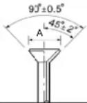 |
| 3/8 27 | b/ft 36.6 Nm 0.472 | -0.488 | |
| 1/2 40 | b/ft 54.2 Nm 0.488 | -0.654 | |
| 5/8 50 | b/ft 67.8 Nm 0.732 | -0.748 | |
| 3/4 80 | b/ft 108.5 Nm 0.902 | -0.917 |
G. Each tube must be insulated with a minimum of 1/2 inch (12.7mm) closed-foam insulation that is UV resistant and meets ASTM Standard E84 25/50 flame spread/smoke development.
H. The lineset between the indoor and outdoor must not exceed the listed maximum length and maximum height difference. See chart below.
| System Models | Liquid | Vapor | Minimum Length | Maximum Length | Maximum Height Difference |
| 1U09TE1VHA | 1/4 in | 3/8 in | 10ft (3m) | 66ft (20m) | 33ft (10m) |
| AW09TE1VHA | |||||
| 1U09TE2VHA | 1/4 in | 3/8 in | 10ft (3m) | 66ft (20m) | 33ft (10m) |
| AW09TE2VHA | |||||
| 1U12TE1VHA | 1/4 in | 3/8 in | 10ft (3m) | 66ft (20m) | 33ft (10m) |
| AW12TE1VHA | |||||
| 1U12TE2VHA | 1/4 in | 3/8 in | 10ft (3m) | 66ft (20m) | 33ft (10m) |
| AW12TE2VHA | |||||
| 1U18TE2VHA | 1/4 in | 1/2 in | 10ft (3m) | 83ft (25.3m) | 50ft (15m) |
| AW18TE2VHA | |||||
| 1U24TE2VHA | 1/4 in | 1/2 in | 10ft (3m) | 83ft (25.3m) | 50ft (15m) |
| AW24TE2VHA | |||||
| 1U24TL2HFA | 3/8 in | 5/8 in | 10ft (3m) | 165ft (50m) | 100ft (30m) |
| AW24TL2HFA | |||||
| 1U3036TL2HFA | 3/8 in | 5/8 in | 10ft (3m) | 165ft (50m) | 100ft (30m) |
| AW30TL2HFA | |||||
| 1U3036TL2HFA | 3/8 in | 5/8 in | 10ft (3m) | 165ft (50m) | 100ft (30m) |
| AW36TL2HFA |
Part 4: Electrical Requirements
4.1 Electrical Supply
A. The 1U09TE1VHA and 1U12TE1VHA heat pump models shall be 115 volts AC, single-phase, 60 hertz. Voltage limitation supplied to the outdoor shall be between 104\~127 volts.
B. The 1U09TE2VHA, 1U12TE2VHA, 1U18TE2VHA, 1U24TE2VHA, 1U24TL2HFA, and 1U3036TL2HFA heat pump models shall be 208/230 volts AC, single-phase, 60 hertz. Voltage limitation supplied to the outdoor shall be between 187\~253 volts.
C. Power supply must be installed in accordance to NEC standards.
4.2 Connecting Wire to Indoor
A. Connecting cable between the indoor unit(s) must be made with 4 conductor - 14 AWG stranded copper wire.
B. Connecting wire must be continuous (without break) unless local code requires power disconnect next to indoor unit. See indoor electrical section 3.1 for the specification.
OUTDOOR UNIT
Part 1: General
1.1 Outdoor Unit
A. The Haier Tempo outdoor unit shall be comprised of a condenser coil with all components and controls necessary to perform the rated operation.
1.2 Warranty
A. The outdoor unit shall be covered by a manufacturer's parts warranty. See Appendix for details.
1.3 Sound Pressure Rating
| Model Sound | Pressure Rating dB (A) |
| 1U09TE1VHA 47 | |
| 1U09TE2VHA 48 | |
| 1U12TE1VHA 50 | |
| 1U12TE2VHA 50 | |
| 1U18TE2VHA 56 | |
| 1U24TE2VHA 53 |
Part 2: Installation
2.1 Condensate
A. The installer must adhere to local building codes for managing condensate water produced by the outdoor unit.
2.2 Clearances
A. The installer must follow the recommended clearances provided in the Installation Manual.
Part 3: Components
3.1 Coil
A. The outdoor coil shall be made with a blue colored hydrophilic coating on the aluminum fins and packed with internally grooved copper tubing, to increase the effective heat exchange surface area by 25%, resulting in higher efficiencies and shorter defrost cycles (approx. 29%.)
B. Coils shall be helium pressure tested at the factory within a range of 600 - 650 PSI.
C. Outdoor unit shall be factory charged with R-410A refrigerant for 25 feet of lineset.
3.2 Fan Motor
A. The outdoor fan motor shall be a brushless, variable speed DCV motor type.
B. The fan motor shall be molded with heat-hardened resin.
C. The fan motor shall have permanently lubricated SRC bearings.
3.3 Fan Blade
A. The outdoor fan blade shall be a UL flame rated plastic-resin design.
B. The fan blade shall be factory balanced in quiet performance and enhanced velocity.
3.4 Compressor
A. The compressor shall be a DC rotary type and A-PAM inverter-driven for stable operation in lower and higher frequency.
B. The compressor shall be vairable speed, variable capacity.
C. The compressor shall have an internal overload protection device.
D. The compressor shall use PVE (FV50S) refrigerant oil for better anti-wear effectiveness, superior resistance to capillary tube blockage and no hydrolysis compared to POE oil.
3.5 4WV
A. The outdoor unit shall contain a four-way reversing valve (4WV) to change system mode from cool to heat.
3.6 EEV
A. The refrigerant flow shall be regulated by an electronic expansion valve (EEV).
B. The outdoor control shall monitor the refrigerant flow through the EEV using a pulse-operated coil.
C. The EEV shall maintain the target of 10^ F ( 5.5^ C) of superheat.
3.7 Base Pan
A. The base pan shall be constructed of commercial grade DC51/DC52 hot-dip galvanized steel with coating.
B. The outdoor unit shall ship with a drain port adapter sized for 1/2 inch tubing to manage condensate run off.
OUTDOOR UNIT
Part 3: Components (continued)
3.9 Copper Piping
A. All internally connected copper tubing shall conform to ASTM B280 tubing tolerances.
3.10 Outdoor Enclosure Materials
A. The outdoor cabinet shall be constructed of commercial grade DC51/DC52 hot-dip galvanized steel with coating.
3.11 Defrost
A. The outdoor unit shall have a reverse-cycle (hot gas) defrost system to maximize heat pump operation and minimize energy consumption.
3.12 Accumulator
A. The accumulator shall be connected to the compressor return line to prevent liquid refrigerant from entering the compressor during operation.
WALL MOUNT INDOOR UNIT
Part 1: General
1.1 Description
A. The wall mounted indoor section completes the system when connected to the matching outdoor unit and field-supplied piping and wiring.
1.2 Warranty
A. The wall mounted indoor unit shall be covered by a manufacturer's parts warranty. See Appendix for detail.
1.3 Sound Pressure Rating
| Model Blower | Pressure Sound Rating dB(A)(Turbo/High/Medium/Low/Quiet) |
| AW09TE1VHA 3 | 9/37 /33/28/23 |
| AW09TE2VHA 4 | 2/36/33/29/26 |
| AW12TE1VHA 3 | 9/37 /33/28/23 |
| AW12TE2VHA 4 | 2/38/34/31/26 |
| AW18TE2VHA 4 | 5/43/39/36/33 |
| AW24TE2VHA 4 | 7/45/40/37/34 |
Part 2: Installation Requirements
2.1 Condensate
A. The wall mouted indoor shall be shipped with a insulated polyethylene condensate tubing (5/8" ID) attached from the factory.
B. The wall mounted indoor unit shall ship with a 6.5 ft (2m) corrugated drain tube that connects to the insulated drain tube.
C. The wall mounted indoor unit shall be a gravity drain.
2.2 Clearances
A. The installer must follow the minimum clearances illustrated in the Installation Manual when installing the indoor unit.
2.3 Mounting
A. The wall mounted indoor unit shall ship with a galvanized metal wall bracket.
B. The wall bracket shall have multiple anchor points to provide the installer with many options to firmly attach the wall mounted indoor unit to the wall.
C. The field-supplied mounting hardware must be sufficient to adequately support the indoor unit.
WALL MOUNT INDOOR UNIT
Part 3: Electrical Requirements
3.1 Electrical Disconnect
A. Connecting wire must be continuous (without break) unless local code requires a disconnect at the indoor unit.
| Model Fan Motor Rating (HP) |
| AW09TE1VHA 0.064 |
| AW09TE2VHA 0.064 |
| AW12TE1VHA 0.064 |
| AW12TE2VHA 0.064 |
| AW18TE2VHA 0.064 |
| AW24TE2VHA 0.094 |
B. If a disconnect is required by local code, it must be a 3-pole, single-throw type.
Part 4: Components
4.1 Coil
A. The indoor coil shall be made with a blue colored hydrophilic coating on the aluminum fins and packed with internally grooved copper tubing, to increase the effective heat exchange surface area by 25%.
B. Copper tubing shall have inner micro-grooves to increase effective heat transfer capabilities.
C. Coils shall be pressure tested at 600\~650 PSI using helium leak detection.
D. The coil shall be charged with dry nitrogen for shipping at 70\~100 PSI.
4.2 Fan Motor
A. The fan motor shall be a sealed DC multiple-speed resin-packed motor
B. The fan motor shall have permanently lubricated bearings.
C. The AW18TE2VHA and AW24TE2VHA shall have an optimized fan motor and blower design to enable up to 40 feet of air flow.
D. The AW09TE1VHA, AW09TE2VHA, AW12TE1VHA, AW12TE2VHA, AW24TL2HFA, AW30TL2HFA, and AW36TL2HFA shall have an optimized fan motor and blower design to enable up to 60 feet of air flow.
4.3 Fan Blade
A. The fan blade shall be a corrosion-resistant cross-flow blower.
B. The fan shall be designed with optimized diameter and surface area to deliver quiet and even air flow.
4.4 Copper Piping
A. The coil shall be connected to a length of insulated annealed copper.
B. The ends of the tubing shall have male flare connections.
4.5. Air Louvers
A. The supply air shall be distributed by horizontal and vertical motorized louvers.
B. Air Louvers shall provide wide angle of operation for both horizontal (120°) and vertical (90° from top to down) airflow movement to provide room comfort for each corner.
4.6 Display
A. The wall mounted indoor unit shall have a 4.5 × 1.1 -inch backlit temperature display capable of showing set or room temperatures.
B. The display shall also have colored icons representing set mode.
C. The display can be turned off from the wireless remote control.
4.7 WiFi
A. The AW09TE1VHA, AW12TE1VHA, AW18TE2VHA and AW24TE2VHA wall mounted indoor unit shall be capable of connecting to WiFi using an adapter.
B. The AW09TE2VHA, AW12TE2VHA, AW24TL2HFA, AW30TL2HFA, and AW36TL2HFA wall mounted indoor units shall come equipped with WiFi capabilities..
4.8Filter
A. The wall mounted indoor unit shall have removable air filters.
B. The air filters shall be washable and reusable.
4.9 Control
A. The wall mounted indoor unit shall ship with the Standard hand-held remote control.
B. The wall mounted indoor unit shall be compatible with the Simple Wired Controller and the Programmable Wired
4.10 Installation Clip
A. The wall mounted indoor unit shall have a built-in clip that swings out and acts as a kick stand to allow for easier access to the rear of the unit during installation and repair.
CONTROLS AND ACCESSORIES
Part 1: Standard Remote Control
1.1 General
A. Standard Remote Control shall be compatible with Haier wall mounted and cassette indoor units.
B. Standard Remote Control shall come packaged with wall mounted and compact cassette indoor units
1.2 Connection
A. Standard Remote Control shall be infrared.
1.3 Warranty
A. The warranty shall cover all defects in workmanship or material for a period of 1 year. Haier will provide a new or refurbished controller at its sole discretion.
1.4 Features
A. The wireless control shall have a power button, individual mode buttons (Heat, Cool, Dry), temperature +/-, fan speed, vertical and horizontal louver adjustments.
B. The wireless control shall be capable of setting a precise temperature of ±1^ ( ±0.5^ ).
C. The wireless control shall have a backlight.
D. The wireless control shall have a child lock function.
E. The wireless control shall have the ability to turn on/off the indoor unit display.
F. The wireless control shall display either Fahrenheit or Celsius.
Part 2: Wired Controllers
2.1 General
A. The wired controller shall be a wall-mounted.
2.2 Connection
A. The wired controller shall connect to an indoor unit using the supplied cable.
B. Two wired controllers can connect to one indoor unit.
C. A single wired controller shall be able to connect up to 16 of the same model type of indoor units. The connected units shall work in unison as a single zone.
2.3 Compatibility
A. The wired controller shall be compatible with all Haier indoor units. Connection to a wall mounted unit requires a WK-B adapter. If multiple indoor units are connected to the controller, a WK-B adapter is required for each indoor unit.
2.4 Warranty
A. The warranty shall cover all defects in workmanship or material for a period of 1 year. Haier will provide a new or refurbished controller, at its sole discretion.
2.5 Programmable Wired Controller Feature
A. The controller shall have a color display.
B. The wired controller shall have a power button, individual mode buttons (heat, cool, dry), temperature +/-, fan speed, vertical and horizontal louver adjustments.
C. The wired controller shall be capable of setting a precise temperature of ±1^ ( ±0.5^ ).
D. The wired controller shall have a backlight.
F. The wired controller shall have a child lock function.
G. The wired controller shall display either Fahrenheit or Celsius.
H. The wired controller shall have the ability to display indoor ambient temperature.
I. The wired controller shall have a Clean Filter reminder.
J. The wired controller shall display error codes.
K. The wired controller shall be able to be programmed for daily or weekly settings.
CONTROLS AND ACCESSORIES
Part 2: Wired Controllers (continued)
2.7 Simplified Wired Controller Features
A. The wired controller shall have large physical buttons for easy operation.
B. The wired controller shall have a power button, a mode button (heat, cool, dry), a fan speed button, a temperature up button and a temperature down button.
C. The wired controller shall be capable of setting a precise temperature of ±1^ ( ±0.5^ ).
D. The wired controller shall have a backlight.
E. The wired controller shall have vertical and horizontal louver control.
F. The wired controller shall have a child lock function.
G. The wired controller shall display either Fahrenheit or Celsius.
H. The wired controller shall have the ability to display indoor ambient temperature.
I. The wired controller shall have a Clean Filter reminder.
J. The wired controller shall display error codes.
K. The wired controller shall have an infrared receiver that can receive commands from a Haier hand-held remote control.
Part 3: QAWF01A WiFi Adapter
3.1 General
A. The QAWF01A WiFi adapter shall connect to a smart device app that will provide the user the ability to set mode, temperature, and fan speed of the indoor unit.
3.2 Connection
A. The WiFi adapter shall connect to the indoor wall mounted unit via the USB port.
B. The WiFi adapter shall have an app that is compatible with both iOS and Android.
C. The WiFi adapter shall be paired with existing 2.4GHz network
D. The WiFi adapter shall comply with Part 15 of the FCC rules.
3.3 Compatibility
A. The WiFi adapter shall be compatible with all wall mounted indoor units.
3.4 Warranty
A. The warranty shall cover all defects in workmanship or material for a period of 1 year. Haier will provide a new or refurbished controller, at its sole discretion.
3.5 Features
A. The WiFi adapter shall be Google Home compatible.
B. The WiFi adapter shall be Amazon Alexa compatible.
C. The homeowner shall have the ability to install and configure the WiFi adapter.
Part 4: WK-B Interface Kit
4.1 General
A. The WK-B adapter shall be used when connecting a wired controller to a wall mounted indoor unit.
4.2 Connection
A. The WK-B adapter shall connect to the indoor unit with a supplied 3-wire cable.
B. The wired controller shall connect to the WK-B with a supplied 3-wire cable.
4.3 Compatibility
A. The WK-B adapter shall be compatible with all Haier mini-split and multi-split wall mounted indoor units.
B. The WK-B adapter shall be compatible with the Simplified and Programmable Haier wired controllers.
4.4 Warranty
A. The warranty shall cover all defects in workmanship or material for a period of 1 year. Haier will provide a new or refurbished controller, at its sole discretion.
LIMITED WARRANTY
For the product models listed on Attachment 1 (the "Product"), this Standard Limited Warranty is provided to the Original Owner of the Product:
| For The Period Of: Haier Will Replace: | |
| 5 year limited parts warrantyFrom the date of the original purchase | This limited warranty cover all defects in workmanship or material for the mechanical and electrical parts contained in the Product (“Defective Parts”) for a period of 5 years from the Date of Purchase. Haier will provide new or refurbished parts, or a replacement for all or part of the unit, at its sole discretion, to your licensed HVAC technician installer. This warranty also covers all defects in workmanship or material for the unit controller for a period of 1 year. The remote controller is covered by 1-year accessory warranty. The ductless system is covered by standard warranty. Haier will provide a new or refurbished controller, at its sole discretion. |
| 7 year compressor warranty from the date of the original purchase | The compressor contained in this product is warranted for a period of 7 years from the Date of Purchase. Haier will provide a new or refurbished compressor, or a replacement for all or part of the unit, at its sole discretion, to your licensed HVAC technician installer. |
WHAT IS THE DATE OF PURCHASE
The “Date of Purchase” is the date that the original installation is complete and all product start-up procedures have been properly completed and verified by the installer's invoice. If the installation date cannot be verified, then the Date of Purchase will be sixty (60) days after the manufacture date, as determined by the Product's serial number. You should keep and be able to provide your original sales receipt from the installer as proof of the Date of Purchase. In new construction, the Date of Purchase will be the date the owner purchased the residence from the builder.
WHO IS COVERED
Owner occupied: The "Original Owner" of this product, which means the original owner (and his or her spouse) of the residence where the Product was originally installed. Subject to the law of the state or province where the Product is installed, this warranty is not transferable to subsequent owners or if the product is moved to a different residence after the initial installation. Non-owner occupied: This limited warranty is provided for product 1) installed in a) single family or multi-family non-owner occupied residential buildings, or b) non-industrial commercial applications, (such as office buildings, retail establishments, hotels/motels) where the product is not subjected to an atmosphere with corrosives or high levels of particulates (such as soot, aerosols, fumes, grease), and 2) if the product is maintained annually by a licensed HVAC technician (proof of annual maintenance is required). The "Original Owner" of the product, means the original owner of the building where the product was originally installed. For new construction, the purchaser of the building from the builder will also be considered an original owner. This warranty is not transferable to subsequent owners or if the product is moved to a different location after the initial installation.
HOW CAN YOU GET SERVICE
Contact your licensed HVAC technician installer. All installation and service must be performed by a licensed HVAC technician. Failure to use a licensed HVAC technician for installation of this Product voids all warranty on this Product..
THIS WARRANTY DOES NOT COVER
• Damage from improper installation.
- Damage in shipping.
- Defects other than from manufacturing (i.e., workmanship or materials).
- Damage from misuse, abuse, accident, alteration, lack of proper care and/or regular maintenance, or incorrect electrical voltage or current.
- Damage resulting from floods, fires, wind, lightning, accidents or similar conditions.
- Damage from installation or other services performed by other than a licensed HVAC technician.
- Labor and related services for repair or installation of the Product.
• A Product purchased from an online retailer.
- Damage as a result of subjecting Product to an atmosphere with corrosives or high levels of particulates (such as soot, aerosols, fumes, grease).
- A Product sold and/or installed outside of the 50 United States, the District of Columbia, or Canada.
- Batteries for the controller and other accessories provided with the Product for installation (e.g., plastic hose).
- Normal maintenance, such as cleaning of coils, cleaning filters, and lubrication.
- For Product installed in non-owner occupied applications, Product that has not been maintained annually by a licensed HVAC technician (proof required).
LIMITED WARRANTY
10 YEAR STANDARD REGISTERED LIMITED WARRANTY
All "Indoor and Outdoor Products," identified in Attachment 1, registered by the installer or the Original Owner within 60 days of the Date of Purchase shall receive a Standard Registered Limited Warranty, which shall be identical to the Standard Base Warranty, except that the Limited Parts Warranty shall be for a term of 10 Years and the Limited Compressor Warranty shall be for a term of 10 years. All Product not registered within 60 days of the Date of Purchase shall be subject to the Standard Base Warranty. Some states and provinces do not allow warranty terms to be subject to registration; in those states and provinces the longer terms for Limited Parts Warranty and the Limited Compressor Warranty apply.
THIS LIMITED WARRANTY IS GIVEN IN LIEU OF ALL OTHER WARRANTIES, EXPRESS OR IMPLIED, INCLUDING THE WARRANTIES OF MERCHANTABILITY AND FITNESS FOR A PARTICULAR PURPOSE.
The remedy provided in this warranty is exclusive and is granted in lieu of all other remedies. This warranty does not cover incidental or consequential damages. Some states and provinces do not allow the exclusion of incidental or consequential damages, so this limitation may not apply to you. Some states and provinces do not allow limitations on how long an implied warranty lasts, so this limitation may not apply to you. This warranty gives you specific legal rights and you may also have other rights which vary by state and province. This warranty covers units within the 50 United States, the District of Columbia and Canada. This warranty it provided by GE Appliances a Haier company, Louisville, KY 40225.
ATTACHMENT 1
The "Product" is defined as Haier brand Ductless Split Units. The "Product" contains 2 sub-categories of goods: "Indoor and Outdoor Products" and "Selected Installation Products," which are further defined below: "Indoor and Outdoor Products" can further be identified by the following model number descriptions: 1U*, 2U*, 3U*, 4U*, AB*, AD*, AL*, AM*, AW*, AF*, MVA* MVH* "Selected Installation Products," identified by the following model number descriptions: PB-* FQG-*-, AH1-*-, MS1-*- and MS3-*
TABLE DES MATIÈRES
DIMENSIONS DE L'APPAREIL ....20
DÉGAGEMENTS DU SYSTÈME....22
SYSTÈME 23
Tension/Cycle/Phase: 208-230/60/1
| Nom de modèle | Système 09TE2 12TE2 18TE2 24 | TE2 | |||
| Extérieur 1U09TE2VHA 1U12TE2 | VHA 1U18TE2VHA 1U18 | TE2VHA | |||
| UPC 0-84691-85533-0 0-84691 | 85535-4 6-88057-40821 | -7 6-88057-40823-1 | |||
| Intérieur AW09TE2VHA AW12TE2 | VHA AW18TE2VHA | TE2VHA AW24 | TE2VHA | ||
| UPC 0-84691-85532-3 0-84691 | 85534-7 6-88057-40820 | -0 6-88057-40822-4 | |||
| Climatisation | Capacité nominale Btu/h | 9,000 | 12,000 | 18,000 24,000 | |
| Plage de capacités Btu/h | 3,800-10,000 | 4,100-13,000 | 5,000-19,000 | 6,500-26,000 | |
| Puissance d'entrée nominale W | 800 | 1,100 | 1,650 | 2,150 | |
| SEER/EER | 18/11.0 | 18/11.0 | 16/10.0 | 16/10.0 | |
| Suppression d'humidité pt./h | 2.3 | 3.4 | 4.2 | 5.9 | |
| Chauffage | Plage des capacités de chauffage Btu/h | 4,100-11,000 | 4,500-13,000 | 5,400-22,000 | 6,800-28,000 |
| Capacité de chauffage nominale 47 °F Btu/h | 10,000 | 12,000 | 19,000 26,000 | ||
| COP | 4.15 | 3.79 | 3.22 | 3.22 | |
| Capacité chauffage nominale 17 °F(-8 °C) Btu/h | 5,000 7,500 11,200 | 16,600 | |||
| Capacité chauffage max. 17 °F (-8 °C) Btu/h | 7,500 | 10,000 | 16,900 20,700 | ||
| Capacité chauffage max. 5°F(-15 °C)Btu/hr | 6,000 8,500 13,500 | 16,400 | |||
| Capacité chauffage max. -4°F (-20 °C)Btu/hr | 5,000 7,500 11,200 | 13,800 | |||
| Puissance d'entrée nominale W | 750 | 980 | 1,700 | 2,400 | |
| HSPF | 10 | 10 | 9.0 | 9.0 | |
| Plage de fonctionnement | Climatisation °F (°C) | -4·115°F (-20-46°C) | -4·115°F (-20-46°C) | 0-115°F (-18-46°C) | 0-115°F (-18-46°C) |
| Chauffage °F (°C) | -4·75°F (-20·24°C) | -4·75°F (-20·24°C) | -4·75°F (-20·24°C) | -4·75°F (-20·24°C) | |
| Unité extérieure | Calibre fusible max. - A | 15 | 15 | 20 | 25 |
| Intensité circuit min. - A | 12 | 12 | 17 | 19 | |
| Niveau sonore extérieur - dB | 48 | 50 | 56 | 53 | |
| Dimension : Hauteur - po (mm) | 21 3/4 (553) | 21 3/4 (553) | 27 7/16 (697) | 30(762) | |
| Dimension : Largeur - po (mm) | 31 1/2 (800) | 31 1/2 (800) | 35 (890) | 36 3/16 (920) | |
| Dimension : Profondeur po (mm) | 10 7/8 (275) | 10 7/8(275) | 13 7/8 (353) | 15 1/8 (385) | |
| Poids (Exp./Net) - lb (kg) | 76.1/63.5 (34.5/28.8) | 82.2/69.7 (37.3/31.6) | 105.8/97.0 (48.0/44.0) | 121.3/112.5 (55.0/51.0) | |
| Unité intérieure | Phases vitesse ventilateur | 5+Auto | 5+Auto | 5+Auto 5+Auto | |
| Débit d'air (Turbo/Haut/Moy/Bas/Silence) pi3/min | 421/332/292/242/200 | 426/360/310/265/200 | 545/530/505/475/460 | 665/650/610/570/555 | |
| Niveau sonore intérieur (Turbo/Haut/Moy/Bas/Silence) dB | 42/36/33/29/26 | 42/38/34/31/26 | 45/43/39/36/33 | 47/45/40/37/34 | |
| Dimension : Hauteur po (mm) | 11 7/8 (301) | 11 7/8(301) | 12 1/2 (318) | 13 3/16 (335) | |
| Dimension : Largeur po (mm) | 33 3/4 (856) | 33 3/4 (856) | 39 11/16 (1008) | 44 5/16 (1125) | |
| Dimension : Prof. po (mm) | 7 3/4 (196) | 7 3/4 (196) | 8 7/8(225) | 9 7/16(240) | |
| Poids (Exp./Net) - lb (kg) | 26.9/21.2 (12.2/9.6) | 26.9/21.2 (12.2/9.6) | 33.1/26.5 (15.0/12.0) | 38.6/30.9 (17 .5/14.0) | |
| Tuyaux de réfrigérant | Raccords | Flare | Flare | Flare | Flare |
| Liquide D.E. po | 1/4 | 1/4 | 1/4 | 1/4 | |
| Aspiration D.E. po | 3/8 | 3/8 | 1/2 | 1/2 | |
| Charge d'usine oz | 32.8 | 40.6 | 40.6 | 67.0 | |
| Longueur conduite max. pi (m) | 66 (20) | 66 (20) | 83 (25) 83 (25) | ||
| Hauteur max. pi (m) | 33 (10) | 33 (10) | 50 (15) 50 (15) |