
QS24WP2BEB - Air Conditioning HAIER - Free user manual and instructions
Find the device manual for free QS24WP2BEB HAIER in PDF.

| Product type | Reversible air conditioning (heat pump) ductless split |
| Brand | Haier |
| Model | QS24WP2BEB |
| Refrigerant | R454B (flammable) |
| Power supply | 230 V ~ 60 Hz (14/4 AWG cable recommended) |
| Main functions | Cooling, heating, ventilation, dehumidification, automatic mode |
| Operating range (cooling) | 14 °F to 115 °F (-10 °C to 46 °C) for Tempo 230V models |
| Operating range (heating) | -15 °F to 75 °F (-26 °C to 24 °C) for FlexFit models |
| Refrigerant leak sensor | Factory installed for QS**WP2BEB models |
| Minimum installation clearances | 4 in (10.2 cm) from ceiling, 4 in from sides, 5 ft 11 in (1.8 m) from floor |
| Minimum room area (with sensor) | Varies by refrigerant charge; e.g., for charge ≤3.9 lb: no restriction |
| Indoor unit type | High wall, ductless |
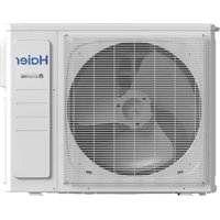
| Outdoor unit | Installed separately (see specific manual) |
| Air filter | Washable, regular removal and cleaning recommended |
| Remote control | Wireless, included with bracket and AAA batteries |
| Parts warranty | 5 years (standard), 10 years (registered online within 60 days) |
| Remote control warranty | 1 year |
| Compliance | UL 60335-2-40 Edition 4 |
| Connectivity | Wi-Fi (software update recommended) |
| Optional accessory | Wired controller QACT17* |
Frequently Asked Questions - QS24WP2BEB HAIER
User questions about QS24WP2BEB HAIER
0 question about this device. Answer the ones you know or ask your own.
Ask a new question about this device
Download the instructions for your Air Conditioning in PDF format for free! Find your manual QS24WP2BEB - HAIER and take your electronic device back in hand. On this page are published all the documents necessary for the use of your device. QS24WP2BEB by HAIER.
USER MANUAL QS24WP2BEB HAIER
Duct less Single Zone with Highwall Indoor Unit
natural_image
Line drawing of a Haier air conditioner unit (no text or symbols on the device itself)Design may vary by model number.
This owner's manual is only printed in English and French. For Spanish version, please visit
GEAppliancesairandwater.com
KEEP THESE INSTRUCTIONS.
TABLE OF CONTENTS
PACKAGE CONTENTS....2
IMPORTANT SAFETY INFORMATION .... 3
Step 1 - Preparation....13
Step 2 - Installation of Indoor Unit .... 15
Wall Brackets....17
Step 3 - Installation of Outdoor Unit .... 17
Step 4 - Safety Switch Control Wiring .... 17
Step 5 - Final Check....18
LIMITED WARRANTY 21
PACKAGE CONTENTS
Included Items
A. Mounting plate 1 B. Installation template 1 C. Screw suite 1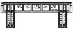 | 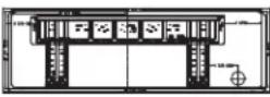 | 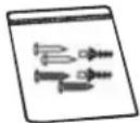 | ||
D. Wireless remote controller and holder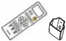 | 1E. Dry battery AAA | 2 | F. Copper nuts | 2 |
G. Operation manual | 1H. Installation manual | 1 | I. Indoor Unit | 1 |
IMPORTANT SAFETY INFORMATION
WARNING
For your safety; the information in this manual must be followed to minimize the risk of fire, electric
shock, or personal injury.
- Use this equipment only for its intended purpose as described in this manual.
- This heat pump must be properly installed in accordance with these instructions before it is used.
- All wiring should be rated for the amperage value listed on the rating plate. Use only copper wiring.
- All electrical work must be completed by a qualified electrician and completed in accordance with local and national building codes.
For any service which requires entry into the refrigerant sealed system, Federal regulations require that the work is performed by a technician having a Class II or Universal certification.
- All air conditioners contain refrigerants, which under federal and/or local law must be removed prior to product disposal. If you are getting rid of an old product with refrigerants, check with the company handling disposal.
• These R454B heat pumps systems require that contractors and technicians use tools, equipment and safety standards approved for use with this refrigerant. - DO NOT use equipment certified for R22,R32 or R410A refrigerant only.
WARNING
RISK OF ELECTRIC SHOCK. Could cause injury or death.
- An adequate ground is essential before connecting the power supply or charging with refrigerant.
- Disconnect all connected electric power supplies before servicing.
- Aluminum building wiring may present special problems - consult a qualified electrician.
- The surrounding conditions (ambient temperature, direct sunlight, and rainwater) shall be noticed during electrical wiring, with effective protective measures being taken.
-
The dedicated branch circuit must be used, and leakage protector with sufficient capacity must be installed.
-
Repair or replace immediately all electrical wiring that has become frayed or otherwise damaged. Do not use wiring that shows cracks or abrasion damage along its length or at either end.
- When the unit is in the STOP position, there is still voltage to the electrical controls.
- Copper wire cable in line with local standards shall be used as the power line and connector wire.
- Both the indoor unit and outdoor unit shall be reliably earthed.
- Wiring for the outdoor unit shall be made first and then the indoor unit. The air conditioner can only be powered on after wiring and pipe connection.
WARNING
RISK OF FIRE. Could cause injury or death.
- Do not store or use combustible materials, gasoline or other flammable vapors or liquids in the vicinity of this or any other appliance.
ATTENTION
- Please do not use extension cords in this system.
- Aluminum building wiring may have special problems, please consult a licensed electrician.
- If the unit has the leak detection system installed, the unit must be powered except for service.
READ AND SAVE THESE INSTRUCTIONS
IMPORTANT SAFETY INFORMATION
For more help, visit geappliancesairandwater.com or call the technical support line at 1.844.487.9443
BEFORE YOU BEGIN
Read these instructions completely and carefully.
- IMPORTANT — Save these instructions for local inspector's use.
- IMPORTANT – Observe all governing codes and ordinances.
- Note to installer – Be sure to leave these instructions with the Consumer.
- Note to consumer – Keep these instructions for future reference.
- Skill level – A licensed certified technician (to handle refrigerant, recovery, etc) and a qualified electrician are required for installation and service of this split heat pump system.
- Proper installation is the responsibility of the installer.
- Product failure due to improper installation is not covered under the limited warranty.
- For personal safety, this system must be properly grounded.
- Protective devices (fuses or circuit breakers) acceptable for installation are specified on the nameplate of each unit.
- Make sure to minimize wiring or plumbing inside the wall when installing.
WARNING
- This product is not intended for use by persons (including children) with reduced physical, sensory or mental capabilities, or lack of experience and knowledge, unless they have been given supervision or instruction concerning use of the appliance by a person responsible for their safety.
- Children should be supervised to ensure that they do not play with the product.
- Ensure that the unit shall be installed in accordance with local and national wiring codes.
- For the dimensions of the space necessary for correct installation of the appliance, including the minimum permissible distances to adjacent structures, refer to this document.
- Ensure only approved units are connected together and that all refrigerant line dimensions and refrigerant charging requirements are followed to prevent exceeding the maximum operating pressure.
- ONLY connect units that are labeled with the same refrigerant.
- Any damage of electrical supply must be replaced by the manufacturer, its service agent or similarly qualified persons in order to avoid a hazard.
- Means for disconnection must be incorporated in the fixed wiring in accordance with wiring rules. Disconnect ampere rating must be at least 115% of the Minimum Circuit Ampacity listed on the rating plate for this product. Disconnect must be installed within sight and readily accessible. Refer to local and national electric code for any additional requirements specified in your region of install.
Safety Awareness
- Procedures: Operation shall be made as per controlled procedures to minimize the probability of risks.
- Area: Area shall be divided and isolated appropriately, and operation in an enclosed space shall be avoided. Before the refrigeration system is started or energized, ventilation or opening of the area shall be guaranteed.
- Site inspection: The refrigerant shall be checked.
- Fire control: A fire extinguisher and a "No Smoking" sign shall be placed in the installation area during installation. The installation area shall remain free from fire/ignition sources during installation.
READ AND SAVE THESE INSTRUCTIONS
IMPORTANT SAFETY INFORMATION
Unpacking Inspection
Indoor unit: nitrogen is sealed during the delivery of indoor units (inside the evaporator), and the red sign at the top of the green plastic seal cap on the evaporator air pipes of the indoor unit shall be checked first after unpacking. In case the sign is raised, the nitrogen sealed still exists. Afterwards, the black plastic seal cap at the joint of evaporator liquid pipes of the indoor unit shall be pressed, to check whether nitrogen still exists. In case no nitrogen is released, ensure the indoor unit does not have a leak before continuing with installation.
Inspection on Installation Environment
- Power supply, switches or other high-temperature articles such as the ignition source and oil heater shall be avoided below the indoor unit.
- The power supply shall be provided with grounding wire and be reliably grounded.
- User shall verify in advance whether water/electricity/gas pipelines are hidden in the wall in locations that may be punctured with an electric drill. It is recommended that the through-wall holes reserved shall be used as much as possible.
Safety Principles of Installation
- Favorable ventilation shall be maintained at the place of installation (doors and windows are opened).
- Open fire or high-temperature heat source (including welding, smoking and oven) higher than 548^ F is not allowed within the scope of flammable refrigerant.
- Anti-static measures shall be taken, such as the wearing of cotton clothes and cotton gloves.
- The place of installation shall be convenient for installation or maintenance and cannot be adjacent to heat source and flammable and combustible environment.
- In case of refrigerant leakage of the indoor unit during installation, the valve of the outdoor unit shall be closed immediately, and windows shall be opened, and all the personnel shall be evacuated. After the leakage of refrigerant is handled, the indoor environment shall be subject to concentration detection. Further handling is not allowed until the safety level is reached.
- In case the product is damaged, it must be delivered to the maintenance point. Welding of refrigerant pipelines at the user's site is not allowed.
- The installation position of air conditioner shall be convenient for installation or maintenance. Barriers shall be avoided around the air inlet/outlet of the indoor/outdoor unit, and the electrical appliance, power switches, sockets, valuables, and high-temperature products within the scope of both sidelines of the indoor unit shall be avoided.
CAUTION
- Refrigerant should be only added or removed by a licensed HVAC technician.
- Before adding additional refrigerant, perform air purging from the refrigerant pipes and indoor unit using a vacuum pump, then charge additional refrigerant.
READ AND SAVE THESE INSTRUCTIONS
Requirements for Operation, Service and Installation of Appliances Using Flammable Refrigerants
WARNING
- Do not use means to accelerate the defrosting process or to clean, other than those recommended by the manufacturer.
- The appliance shall be stored in a room without continuously operating ignition sources (for example: open flames, an operating gas appliance or an operating electric heater.
- Do not pierce or burn.
- Be aware that refrigerants may not contain an odor.
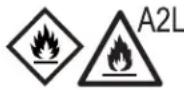
Warning; Flammable Materials, Refrigerant class per ISO 817

Owner's Manual; Operating Instructions

Read Owner's Manual

Service Indicator; Read Technical Manual
General
– During installation, due to the extended refrigerant pipes, additional REFRIGERANT may be charged. Please complete the REFRIGERANT label provided in the manual, and securely paste it near the appliance marking.
– Handling, installation, cleaning, servicing and disposal of refrigerant must comply with the local regulation and the instruction.
– Servicing shall be performed only as recommended by the manufacturer.
- Spaces where refrigerant pipes are allowed shall comply with the below requirement:
- that piping material, pipe routing, and installation shall include protection from physical damage in operation and service, and be in compliance with national and local codes and standards, such as ASHRAE 15, IAPMO Uniform Mechanical Code, ICC International Mechanical Code, or CSA B52. All field joints shall be accessible for inspection prior to being covered or enclosed.
- that the installation of pipe-work shall be kept to a minimum.
- that mechanical connections made at joints that made in the installation between parts of the refrigerating system in shall be accessible for maintenance purposes.
- that protection devices, piping, and fittings shall be protected as far as possible against adverse environmental effects, for example, the danger of water collecting and freezing in relief pipes or the accumulation of dirt and debris.
- that piping in refrigeration systems shall be so designed and installed to minimize the likelihood of hydraulic shock damaging the system.
- that precautions shall be taken to avoid excessive vibration or pulsation.
Requirements for Operation, Service and Installation of Appliances Using Flammable Refrigerants
General (cont.)
- that after completion of field piping for split systems, the field pipework shall be pressure tested with an inert gas and then vacuum tested prior to refrigerant charging, according to the following requirements:
- The minimum test pressure for the low side of the system shall be the low side design pressure and the minimum test pressure for the high side of the system shall be the high side design pressure, unless the high side of the system, cannot be isolated from the low side of the system in which case the entire system shall be pressure tested to the low side design pressure.
- The test pressure after removal of pressure source shall be maintained for at least 1 hour with no decrease of pressure indicated by the test gauge, with test gauge resolution not exceeding 5% of the test pressure.
- During the evacuation test, after achieving a vacuum level specified in the manual or less, the refrigeration system shall be isolated from the vacuum pump and the pressure shall not rise above 1500 microns within 10 min. The vacuum pressure level shall be specified in the manual, and shall be the lessor of 500 microns or the value required for compliance with national and local codes and standards, which may vary between residential, commercial, and industrial buildings.
- that field-made refrigerant joints indoors shall be tightness tested according to the following requirements: The test method shall have a sensitivity of 5 grams per year of refrigerant or better under a pressure of at least 0.25 times the maximum allowable pressure. No leak shall be detected.
Qualification of workers
The manual shall contain specific information about the required qualification of the working personnel for maintenance, service and repair operations. Every working procedure that affects safety means shall only be carried out by competent persons.
Examples for such working procedures are:
- breaking into the refrigerating circuit;
- opening of sealed components;
- opening of ventilated enclosures.
The competent persons are trained by the national training organizations or manufacturers that are accredited to teach the relevant national competency standards that may be set in legislation. The achieved competence should be documented by a certificate.
Information on servicing
Prior to beginning work on systems containing FLAMMABLE REFRIGERANTS, safety checks are necessary to ensure that the risk of ignition is minimized. For repair to the REFRIGERATING SYSTEM, the below requirement shall be completed prior to conducting work on the system:
- Work shall be undertaken under a controlled procedure so as to minimise the risk of a flammable gas or vapor being present while the work is being performed.
– All maintenance staff and others working in the local area shall be instructed on the nature of work being carried out. Work in confined spaces shall be avoided.
- The area shall be checked with an appropriate refrigerant detector prior to and during work, to ensure the technician is aware of potentially toxic or flammable atmospheres. Ensure that the leak detection equipment being used is suitable for use with all applicable refrigerants, i. e. non-sparking, adequately sealed or intrinsically safe.
- If any hot work is to be conducted on the refrigerating equipment or any associated parts, appropriate fire extinguishing equipment shall be available to hand. Have a dry powder or CO2 fire extinguisher adjacent to the charging area.
Requirements for Operation, Service and Installation of Appliances Using Flammable Refrigerants
Information on servicing (cont.)
- No person carrying out work in relation to a REFRIGERATING SYSTEM which involves exposing any pipe work shall use any sources of ignition in such a manner that it may lead to the risk of fire or explosion. All possible ignition sources, including cigarette smoking, should be kept sufficiently far away from the site of installation, repairing, removing and disposal, during which refrigerant can possibly be released to the surrounding space. Prior to work taking place, the area around the equipment is to be surveyed to make sure that there are no flammable hazards or ignition risks. “No Smoking” signs shall be displayed.
- Ensure that the area is in the open or that it is adequately ventilated before breaking into the system or conducting any hot work. A degree of ventilation shall continue during the period that the work is carried out. The ventilation should safely disperse any released refrigerant and preferably expel it externally into the atmosphere.
- Where electrical components are being changed, they shall be fit for the purpose and to the correct specification. At all times the manufacturer's maintenance and service guidelines shall be followed. If in doubt, consult the manufacturer's technical department for assistance.
– The following checks shall be applied to installations using FLAMMABLE REFRIGERANTS:
- marking to the equipment continues to be visible and legible. Markings and signs that are illegible shall be corrected;
- refrigerating pipe or components are installed in a position where they are unlikely to be exposed to any substance which may corrode refrigerant containing components, unless the components are constructed of materials which are inherently resistant to being corroded or are suitably protected against being so corroded.
– Repair and maintenance to electrical components shall include initial safety checks and component inspection procedures. If a fault exists that could compromise safety, then no electrical supply shall be connected to the circuit until it is satisfactorily dealt with. If the fault cannot be corrected immediately but it is necessary to continue operation, an adequate temporary solution shall be used. This shall be reported to the owner of the equipment so all parties are advised.
– Initial safety checks shall include:
- that capacitors are discharged: this shall be done in a safe manner to avoid possibility of sparking;
- that no live electrical components and wiring are exposed while charging, recovering or purging the system;
• that there is continuity of earth bonding.
Repairs to sealed components, intrinsically safe components
– Sealed electrical components shall be replaced.
– Intrinsically safe components must be replaced.
– Replace components only with parts specified by the manufacturer. Other parts may result in the ignition of refrigerant in the atmosphere from a leak.
Cabling
Check that cabling will not be subject to wear, corrosion, excessive pressure, vibration, sharp edges or any other adverse environmental effects. The check shall also take into account the effects of aging or continual vibration from sources such as compressors or fans.
Requirements for Operation, Service and Installation of Appliances Using Flammable Refrigerants
Detection of flammable refrigerants
- Under no circumstances shall potential sources of ignition be used in the searching for or detection of refrigerant leaks. A halide torch (or any other detector using a naked flame) shall not be used.
– The following leak detection methods are deemed acceptable for all refrigerant systems.
- Electronic leak detectors may be used to detect refrigerant leaks but, in the case of FLAMMABLE REFRIGERANTS, the sensitivity may not be adequate, or may need re-calibration. (Detection equipment shall be calibrated in a refrigerant-free area.) Ensure that the detector is not a potential source of ignition and is suitable for the refrigerant used. Leak detection equipment shall be set at a percentage of the LFL of the refrigerant and shall be calibrated to the refrigerant employed, and the appropriate percentage of gas (25 % maximum) is confirmed.
- Leak detection fluids are also suitable for use with most refrigerants but the use of detergents containing chlorine shall be avoided as the chlorine may react with the refrigerant and corrode the copper pipe-work.
NOTE: Examples of leak detection fluids are:
- bubble method,
-
fluorescent method agents.
-
If a leak is suspected, all naked flames shall be removed/extinguished.
- If a leakage of refrigerant is found which requires brazing, all of the refrigerant shall be recovered from the system, or isolated (by means of shut off valves) in a part of the system remote from the leak. Removal of refrigerant shall be according to the manual.
Removal and evacuation
- When breaking into the refrigerant circuit to make repairs – or for any other purpose – conventional procedures shall be used. However, for flammable refrigerants it is important that best practice be followed, since flammability is a consideration. The following procedure shall be adhered to:
a) safely remove refrigerant following local and national regulations;
b) purge the circuit with inert gas;
c) open the circuit by cutting or brazing.
- The refrigerant charge shall be recovered into the correct recovery cylinders if venting is not allowed by local and national codes. For appliances containing flammable refrigerants, the system shall be purged with oxygen-free nitrogen to render the appliance safe for flammable refrigerants. This process might need to be repeated several times.
- Compressed air or oxygen shall not be used for purging refrigerant systems.
Charging procedures
– In addition to conventional charging procedures, the following requirements shall be followed.
- Ensure that contamination of different refrigerants does not occur when using charging equipment. Hoses or lines shall be as short as possible to minimise the amount of refrigerant contained in them.
- Cylinders shall be kept in an appropriate position according to the instructions.
- Ensure that the REFRIGERATING SYSTEM is earthed prior to charging the system with refrigerant.
- Label the system when charging is complete (if not already).
– Extreme care shall be taken not to overfill the REFRIGERATING SYSTEM.
- Prior to recharging the system, it shall be pressure-tested with the appropriate purging gas. The system shall be leak-tested on completion of charging but prior to commissioning. A follow up leak test shall be carried out prior to leaving the site.
Requirements for Operation, Service and Installation of Appliances Using Flammable Refrigerants
Decommissioning
– Before carrying out this procedure, it is essential that the technician is completely familiar with the equipment and all its detail. It is recommended good practice that all refrigerants are recovered safely. Prior to the task being carried out, an oil and refrigerant sample shall be taken in case analysis is required prior to re-use of recovered refrigerant. It is essential that electrical power is available before the task is commenced.
a) Become familiar with the equipment and its operation.
b) Isolate system electrically.
c) Before attempting the procedure, ensure that:
- mechanical handling equipment is available, if required, for handling refrigerant cylinders;
- all personal protective equipment is available and being used correctly;
- the recovery process is supervised at all times by a competent person;
- recovery equipment and cylinders conform to the appropriate standards.
d) Pump down refrigerant system, if possible.
e) If a vacuum is not possible, make a manifold so that refrigerant can be removed from various parts of the system.
f) Make sure that cylinder is situated on the scales before recovery takes place.
g) Start the recovery machine and operate in accordance with instructions.
h) Do not overfill cylinders (no more than 80 % volume liquid charge).
i) Do not exceed the maximum working pressure of the cylinder, even temporarily.
j) When the cylinders have been filled correctly and the process completed, make sure that the cylinders and the equipment are removed from site promptly and all isolation valves on the equipment are closed off.
k) Recovered refrigerant shall not be charged into another REFRIGERATING SYSTEM unless it has been cleaned and checked.
Labeling
– Equipment shall be labeled stating that it has been de-commissioned and emptied of refrigerant. The label shall be dated and signed. For appliances containing FLAMMABLE REFRIGERANTS, ensure that there are labels on the equipment stating the equipment contains FLAMMABLE REFRIGERANT.
Requirements for Operation, Service and Installation of Appliances Using Flammable Refrigerants
Recovery
- When removing refrigerant from a system, either for servicing or decommissioning, it is recommended good practice that all refrigerants are removed safely.
- When transferring refrigerant into cylinders, ensure that only appropriate refrigerant recovery cylinders are employed. Ensure that the correct number of cylinders for holding the total system charge is available. All cylinders to be used are designated for the recovered refrigerant and labelled for that refrigerant (i. e. special cylinders for the recovery of refrigerant). Cylinders shall be complete with pressure-relief valve and associated shut-off valves in good working order. Empty recovery cylinders are evacuated and, if possible, cooled before recovery occurs.
- The recovery equipment shall be in good working order with a set of instructions concerning the equipment that is at hand and shall be suitable for the recovery of all appropriate refrigerants including, when applicable, FLAMMABLE REFRIGERANTS. In addition, a set of calibrated weighing scales shall be available and in good working order. Hoses shall be complete with leak-free disconnect couplings and in good condition. Before using the recovery machine, check that it is in satisfactory working order, has been properly maintained and that any associated electrical components are sealed to prevent ignition in the event of a refrigerant release. Consult manufacturer if in doubt.
– The recovered refrigerant shall be returned to the refrigerant supplier in the correct recovery cylinder, and the relevant waste transfer note arranged. Do not mix refrigerants in recovery units and especially not in cylinders. - If compressors or compressor oils are to be removed, ensure that they have been evacuated to an acceptable level to make certain that FLAMMABLE REFRIGERANT does not remain within the lubricant. The evacuation process shall be carried out prior to returning the compressor to the suppliers. Only electric heating to the compressor body shall be employed to accelerate this process. When oil is drained from a system, it shall be carried out safely.
Required Tools for Installation
- 5/8" (16mm), 7/8" (22mm), 1" (25mm) or adjustable wrench
- Adhesive tape
- Conduit cable clamp 1/2
• #2 phillips screwdriver - Drill
• R454b flaring tool - Hex wrench
- Hole saw 2 14 "
- Refrigerant scale
- Level
- Manifold gauge set
- Measuring tape
- Micron gauge
-
Mini-split adapter ( 5/16 " F to 1/4 " M)
-
Nitrogen*
- Pipe cutter
- Razor knife
- Reamer
- Saddle clamp (L.S.) w/ screws
- Sealant, non-expanding (for lineset hole)
- Soap/water solution* or gas leakage detector
- Stud finder
- Torque wrench
- Vacuum pump
- Wire strippers
- All usual and customary HVAC hand and power tools, meters, and testing devices
* consumable
INSTALLATION INSTRUCTIONS
MINIMUM CLEARANCES
(Appearance may vary)
This picture is for reference only. Your product may look different. Read your manual before installation. Explain the operation of the unit to the user according to this manual.
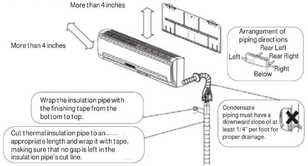
NOTE: * Right piping direction is not possible with refrigerant leak sensor installed.
NOTE: **The suggested placement of the unit is at least 5 feet 11 inches from the floor to the bottom of the unit and at least 4 inches from the ceiling to the top of the unit.
Supplied by Installer
Refrigerant Line Set: for sizing please refer to the Outdoor Unit Rating Plate
• 14/4 AWG SOOW Non-Shielded Stranded Copper Cable
• R454B Refrigerant (if extra charge is needed, see next section)
• Refrigerant Line Insulation (follow local code requirements)
- PVC Pipe (optional)
• Condensate Drain Tubing Clamp
• 16/2 AWG Shielded SOOW Cable for high speed communication
IMPORTANT
NOTE: This air conditioner is designed to be operated under condition as follows and performance may be reduced outside of these operating temperatures.
| Operating Range | Cooling | Tempo 115V | 23°F~115°F(-5°C~46°C)Arctic |
| FlexFit | |||
| Tempo 230V 14°F~115°F(-10°C~46°C) | |||
| Heating | Tempo 115V | -4°F~75°F(-20°C~24°C) | |
| Tempo 230V | |||
| FlexFit -15°F~75°F(-26°C~24°C) | |||
| Arctic -31°F~75°F(-35°C~24°C) | |||
NOTE:
To achieve most efficient operation, operate the indoor unit with fan speed in Auto mode. In Cooling mode, use a set temperature of 78^ F ( 25.5^ C) or higher. In Heating mode, use a set temperature of 73^ F ( 22.5^ C) or lower.
INSTALLATION INSTRUCTIONS
Step 1 - Preparation
A. Before installing the indoor unit, determine allowable room size ^1 .
Refer to the outdoor unit installation instructions for calculating the total refrigerant charge. Measure the area of the space that will be conditioned by the indoor unit, and refer to the below table :
| Highwall without Refrigerant Leak Sensor Installed | |||||||||||||||
| Maximum Charge | Ibs ≤ | 3.9 | 4 | 4.5 | 5 | 5.5 | 6 | 6.5 | 7 | 7.5 | 8 | 5 | 9 | 9.5 | 10 |
| oz ≤ | 62.4 | 64 | 72 | 80 | 88 | 96 | 104 | 112 | 120 | 128 | 136 | 144 | 152 | 160 | |
| Minimum Room Size | ft ^2 No | restriction 74 | 83 | 92 | 101 | 110 | 120 | 129 | 138 | 147 | 166 | 186 | 208 | 230 | |
If your room size is smaller than the minimum room size listed above, a refrigerant leak sensor may be required.
NOTE: Models QS**WP2BEB and QS06WP2BE* already have refrigerant leak sensor factory-installed.
See below table:
| Highwall with Refrigerant Leak Sensor Installed | |||||||||||||||
| Maximum Refrigerant Charge | lbs | ≤3.9 | 4.0 | 4.5 | 5.0 | 5.5 | 6.0 | 6.5 | 7.0 | 7.5 | 8.0 | 8.5 | 9.0 | 9.5 | 10.0 |
| oz | ≤62.4 | 64 | 72 | 80 | 88 | 96 | 104 | 112 | 120 | 128 | 136 | 144 | 152 | 160 | |
| Minimum Room Size - Single Zone Outdoor Unit | ft^2 | No restriction | 74 83 | 92 10 | 1 110 | 120 129 | 138 147 | 156 165 | 175 184 | ||||||
| Minimum Room Size - Multi Zone Outdoor Unit | ft^2 | No restriction | 60 63 | 75 83 | 90 98 | 105 113 | 120 128 | 135 143 | 150 | ||||||
Installation in rooms smaller than the minimum sizes listed above are not allowed based on the standard of UL60335-2-40 Edition 4 ^4 .
1: Calculated based on a minimum install height of 5 ft 11 inches (1.8m) measured from the floor to the bottom of the indoor unit.
2: UL60335-2-40 Edition 4 has been adopted by majority of state and local codes. A limited number of local and state codes may require compliance to UL 60335-2-40 Edition 3. Please refer to our website at geappliancesairandwater.com for guidance on installations in those localities.
NOTE: Additional room area may be needed for different installation altitudes. Please use "Altitude Adjustment Factor" table below by multiplying minimum room size by the altitude adjustment factor based on install altitude.
Altitude Adjustment Factor
| Altitude (m) | 0 | 200 | 400 | 600 | 800 | 1000 | 1200 | 1400 | 1600 |
| Altitude (ft) | 0 | 660 | 1310 | 1970 | 2620 | 3280 | 3940 | 4590 | 5250 |
| Adj. Factor | 1 | 1 | 1 | 1 | 1.02 | 1.05 | 1.04 | 1.1 | 1.12 |
| Altitude (m) | 1600 | 1800 | 2000 | 2200 | 2400 | 2600 | 2800 | 3000 | 3200 |
| Altitude (ft) | 5250 | 5910 | 6560 | 7220 | 7870 | 8530 | 9190 | 9810 | 10500 |
| Adj. Factor | 1.12 | 1.15 | 1.18 | 1.21 | 1.25 | 1.28 | 1.32 | 1.36 | 1.4 |
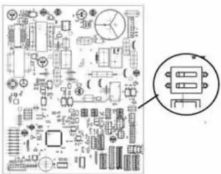
B. If leak sensor is not needed or installed, make sure to flip dip switch 3-2 to OFF (see right picture).
Missing this step will result in getting error code bA.
If leak sensor is needed, please go to step C.
natural_image
Pure electrical circuit lines without any symbolsINSTALLATION INSTRUCTIONS
Step 1 - Preparation (cont.)
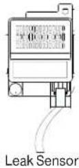
C. Install the Leak Sensor.
Step 1: Find the bracket and remove it from the unit.
Leak sensor bracket is pre-installed on the backside of the unit, please find it and remove it from the unit.
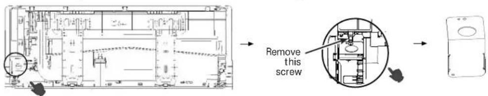
Step 2: Attach the leak sensor into the bracket. (Be sure to use the provided flat screw.)
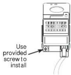
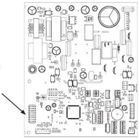
Step 3: Connect the leak sensor to the unit PCB.
Remove the electrical box cover and route the refrigerant leak sensor wire from the back of the unit, pull the PCB out and connect the refrigerant leak sensor to port CN3 on the PCB. Please ensure to route the wire for the refrigerant leak sensor from the back of the high wall to the front, under the electrical box. Please also organize any loose wire so that it doesn't prevent the install of the electrical box cover.
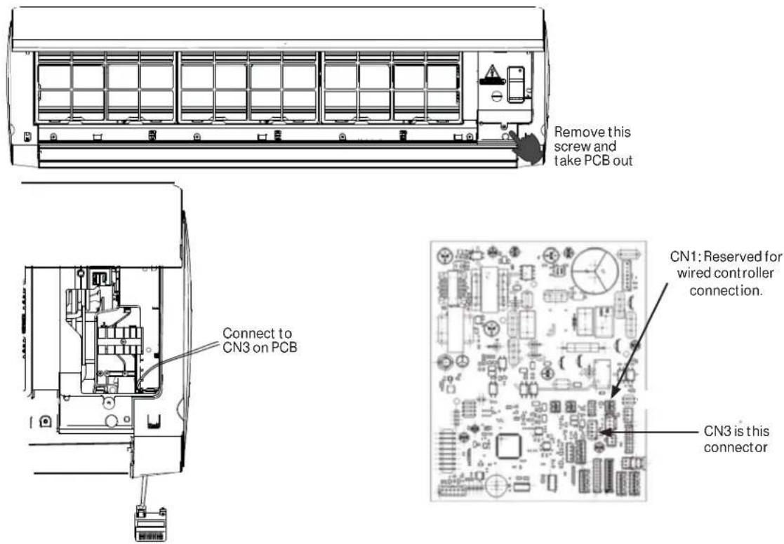
Step 4: Install the bracket with the sensor back to the original location.
INSTALLATION INSTRUCTIONS
Step 1 - Preparation (cont.)
D. Capacity Adjustment (for GS06WP2BE\* models only)
To adjust the software so that the indoor unit runs at 4K Btu/hr capacity, flip dip switch 5-4 to OFF and dip switch 5-3 to ON.
Location of Dip Switched for 6K to 4K capacity adjustment
natural_image
Pure electrical circuit lines without any symbolsStep 2 - Installation of the Indoor Unit
A. Select the Indoor location:
- Do not allow any heat or steam near the unit.
- Select a location where there are no obstacles in front of the unit.
- Make sure that condensate drainage can be conveniently routed away.
- Do not install near a doorway.
- Ensure that the space around the left and right of the unit is more than 4". The unit should be installed as high on the wall as possible but allow a minimum of 4" from the ceiling.
- Use a stud finder to locate and mark stud locations for mounting and to prevent unnecessary damage to the wall.
• Install in a location that is strong enough to withstand the full weight and vibration of the unit. - Leave enough space to allow access for routine maintenance.
- Select a location that gives easy access to removing and cleaning air filters.
• Install in a location that is 3 ft. or more away from other electrical appliances, such as televisions and audio devices.
Wall Brackets
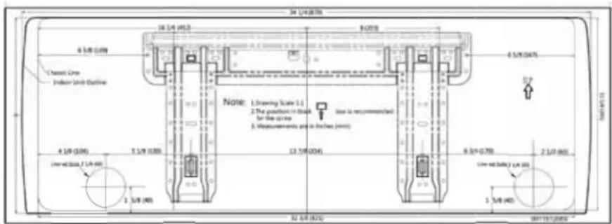
A cardboard template for the mounting plate is included with many of the indoor units. It serves as an easier way of determining where to mount the wall bracket and where to cut the hole for piping.
When mounting the unit, use a stud finder to secure the upper-most holes to the structure of the building. Use load rated anchors to attach other portions of the bracket to the wall.
EXAMPLE
INSTALLATION INSTRUCTIONS
Step 2 - Installation of the Indoor Unit (Cont.)
B. Install the Mounting Plate
- Remove plastic bag, tape, and mounting plate from the back of the indoor unit.
- Place the mounting plate on the wall in the desired location taking into account the minimum clearances necessary for proper operation.
- Using a level, verify that the mounting plate is horizontal and mark the screw locations.
- Attach the mounting plate to the wall with the supplied screws.
- Wall anchors are supplied if not able to align all screw holes with studs.
- Be sure that the mounting plate has been attached firmly and that applied weight is evenly distributed by each screw. (At least one screw in wall stud, others can use wall anchors.)
- The piping for the indoor unit may be routed to and from the unit in one of several directions: left, left rear, right, right rear, or right below.
- Knockouts are provided on the unit case for Left, Right, and Right Below usage.
NOTE: Make sure that support structure for unit has proper load bearing capabilities.
C. Install the Tubing
- Measure and mark the location where the piping hole is to be drilled.
-
Follow these steps to move the drain pipe if the pipe location will be on the left side of the unit.
-
Remove the stopper in the left drain hole and knockout the molded plug inside the port.
- Transfer the corrugate drain hose from the right side to the left side.
-
Insert stopper into right side drain port. Using soap as a lubricant and a small screwdriver will allow for easier seating of the stopper.
-
Drill the lineset hole using a 2 1/4" hole saw. Angle the drill with a downward pitch to the outside wall so that the outside wall hole will be at least a 1/4" lower than the inside hole. This allows for proper drainage of condensate.
- Install the lineset hole flange at the hole opening on the inside wall.
NOTE: The flange is prescored. It may be necessary to modify the flange to fit properly behind the wall unit housing.
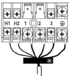
D. Electrical Connections for the Indoor Unit
NOTE: Be certain all wiring complies with local building codes and NEC and that the supply voltage for this system is correct. Refer to rating label electrical ratings.
- Place the indoor unit on a solid work surface before making electrical connections.
- Both the outer plastic and inner galvanized steel cover plates must be removed to make the electrical connections for the indoor unit.
- Raise the front cover to access the screws for removing these covers.
- Route the 14/4 AWG wiring through the slot in the back of the unit and into the front access panel.
- Using a wire stripper, remove the insulation and separate the 4 wires.
- Spade terminals are recommended. If spade terminals are not used then the wires should not be twisted prior to connecting to the screw terminals.
- Make wiring connections at each terminal according to wiring diagram. Take note of the color of the wire at each terminal and ensure the wires are connected to the outdoor unit accordingly.
- Ensure each wire is under the screw terminal plate and the plate is tightened with no fraying.
- Ensure the 14/4 cable is secured under the strain relief bracket.
- After the terminal block wiring is completed, replace both cover plates and lower the front casing.
NOTE: When making the H1 and H2 connection to the outdoor unit, use 16/2 stranded shielded cable.
Indoor Unit Control Wiring
INSTALLATION INSTRUCTIONS
Step 2 - Installation of the Indoor Unit (Cont.)
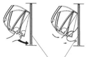
E. Mount Indoor Unit to Mounting Plate
- Bundle the refrigerant piping, drain piping, and wiring with tape and carefully rout the bundle through the piping hole.
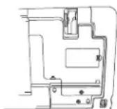
- With the top of the indoor unit closer to the wall, hang the indoor unit on the upper hooks of the mounting plate. Slide the unit slightly side to side to verify proper placement.
- Rotate the lower portion of the indoor unit to the mounting plate, and lower the unit onto the lower hooks of the mounting plate. (see illustration)
- Verify the unit is secured and flush to the wall.
- Indoor Unit installation is finished at this time.
natural_image
Diagram showing two mechanical or structural states with arrows indicating motion, no text or symbols presentmounting plate
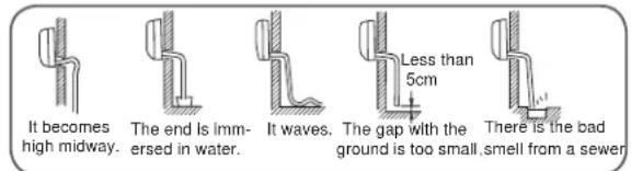
F. Condensate Drainage Pipe
- Verify the condensate drain line has a constant pitch downward for proper water flow. There should be no kinks or rises in the tubing which may cause a trapping effect of the water (see illustration).
- Optional: Can use PVC pipe by connecting a 1" ID PVC pipe to the drain line coming out of the wall and running to desired location.
STOP
G. To Remove the Indoor Unit
- Slightly raise the entire unit.
- Pull the lower portion of the unit off the lower hooks and pull slightly away from the wall.
- Lift the upper portion of the unit off the upper hooks.
Step 3 - Installation of the Outdoor Unit
Please refer to outdoor installation manual in outdoor carton.
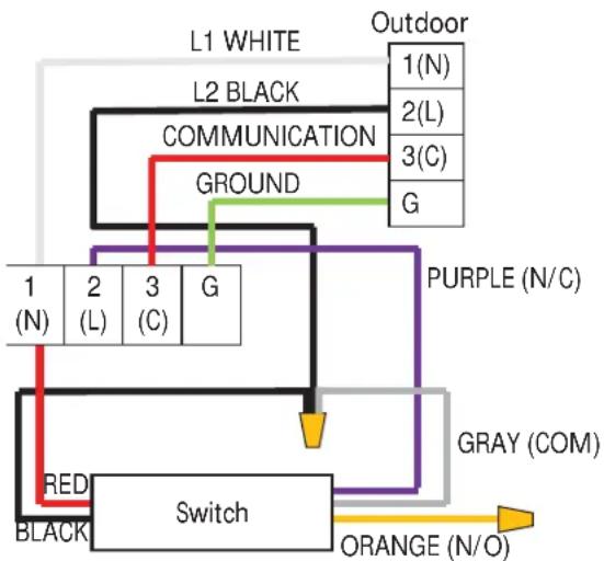
Step 4 - Safety Switch Control Wiring
If a condensate flood switch is required, follow sample wiring diagram.
flowchart
graph TD
    A["L1 WHITE"] --> B["COMMUNICATION"]
    C["L2 BLACK"] --> B
    D["Outdoor"] --> E["GROUND"]
    F["1(N)"] --> G["1(N)"]
    H["2(L)"] --> I["2(L)"]
    J["3(C)"] --> K["3(C)"]
    L["G"] --> M["G"]
    N["PURPLE (N/C)"] --> O["Gray (COM)"]
    P["RED"] --> Q["Switch"]
    R["BLACK"] --> Q
    S["ORANGE (N/O)"] --> T["Orange"]
    U["Ground"] --> V["Ground"]
INSTALLATION INSTRUCTIONS
Step 5 - Final Check
Explaining Operation to the End User
- Using the User Manual, explain to the user how to use the air conditioner/heat pump, (the remote controller, adding/removing the air filters, placing or removing the remote controller from the remote control holder, cleaning methods, precautions for operation, etc.)
- Review precautions for operation.
- Recommend that the user read the Operating Instructions carefully.
Check Items for Test Run
☐ No gas leak from linesets?
□ Are the linesets insulated properly?
☐ Are the connecting wirings of indoor and outdoor firmly inserted to the terminal block?
☐ Is the connecting wiring of indoor and outdoor fixed?
□ Is condensate draining correctly?
☐ Is the ground wire securely connected? Is the indoor unit securely fixed?
☐ Is power source voltage correct according to local code?
□ Is there any odd noise?
☐ Does the cooling temperature drop between 20-30°F?
☐ Does the heating temperature raise between 35-40°F?
□ Is the room temperature display accurate?
Verify Refrigerant Leak Sensor Function
When a refrigerant leak or other leak sensor related error is detected, the indoor fan will turn on at high speed, and the compressor on the outdoor unit will turn off. These functions can be verified by temporarily disconnecting the leak sensor from the indoor unit and waiting up to 30 seconds for the system response. The leak sensor connects to connector CN3 on the indoor PCB (see section C for reference). When the system is powered on and the leak sensor is disconnected, the indoor unit should display "Ac," turn on the fan at high speed, and turn the compressor in the outdoor unit off. When the system is powered off, the leak sensor is disconnected, and the system is powered on, the indoor unit should display "bA," turn on the fan at high speed, and turn the compressor on the outdoor unit off.
Software Notice
To ensure product is functioning optimally and with the latest feature set, connect AC unit to WiFi and update with latest software. Refer to Owner's Manual on how to connect WiFi.
QACT17\* wired controller (optional accessory)
If installing a wired controller, use 18/2 stranded wire and connect the wiring to connector CN1 on the indoor unit PCB. See section C of Step 1 in this manual for the location of CN1 on the PCB.
INSTALLATION INSTRUCTIONS
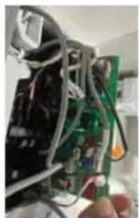
Refrigerant Leak Sensor Replacement Instructions
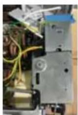
This maintenance operation is applicable for 6k through 24k models. Specific maintenance steps as shown in the figures below. Remove the old leak sensor by performing steps 1 to 4 in sequence and repeat steps 4 to 1 to reinstall the new leak sensor.
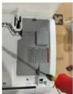
natural_image
Close-up of a white electronic device with a red tool inserted, showing internal components and wiring (no visible text or symbols)- Remove front cover.
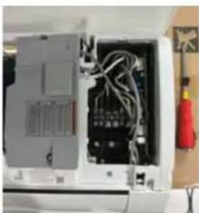
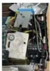
natural_image
Interior view of an electronic device showing internal wiring and components (no visible text or symbols)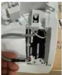
natural_image
Close-up of a hand holding a small electronic device with visible wiring and components (no text or symbols)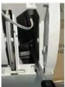
natural_image
Close-up of a mechanical device with internal components and wiring (no visible text or symbols)- Remove leak sensor.
natural_image
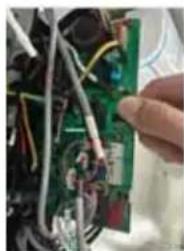
Close-up of electronic circuit board with wires and components (no visible text or symbols)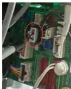
natural_image
Close-up of an electronic circuit board with visible components and wiring (no readable text or symbols)- Pull out the PCB and unplug the refrigerant leak sensor from CN3.
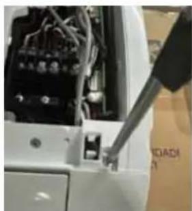
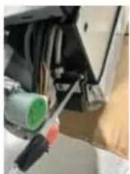
natural_image
Close-up of a white car interior with visible wiring and a screwdriver inserted (no text or symbols)- Remove right trim panel.
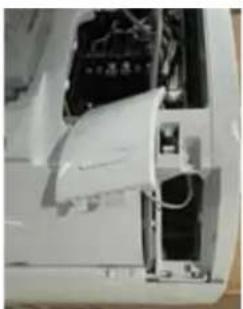
natural_image
Close-up of a white electronic device with visible internal components and wiring (no text or symbols)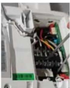
natural_image
Interior view of an electrical enclosure with visible wiring and components (no readable text or symbols)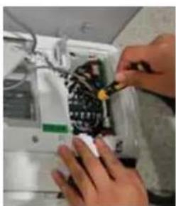
natural_image
Close-up of hands installing or repairing a black electronic component with wires (no visible text or symbols)- Remove 1 screw to remove the terminal block (QS06WP2BE* models only).
INSTALLATION INSTRUCTIONS
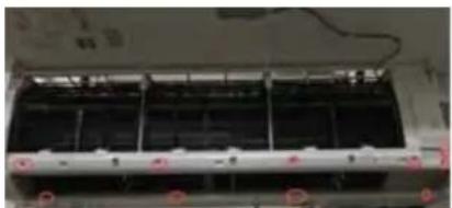
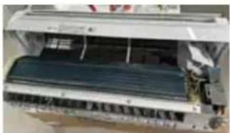
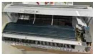
This maintenance operation is applicable for 30k through 36k models. Specific maintenance steps as shown in the figures below. Remove the old leak sensor by performing steps 1 to 6 in sequence and repeat steps 6 to 1 to reinstall the new leak sensor.

natural_image
Interior view of a vehicle showing a large black panel with three windows and a red rectangular overlay (no visible text or symbols)- Remove the louver.
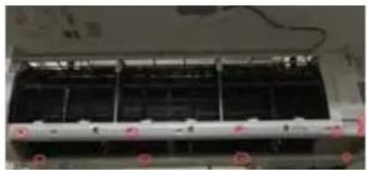
natural_image
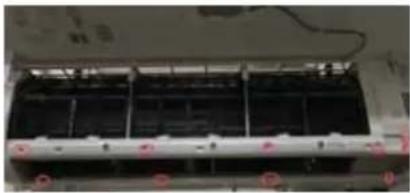
Interior view of an air conditioner unit with cooling fins and ventilation grilles (no visible text or labels)- Remove the screws.
natural_image
Close-up of an air conditioner unit with visible cooling cover and mechanical components (no text or symbols)- Remove the cover by removing these 10 screws.
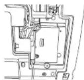
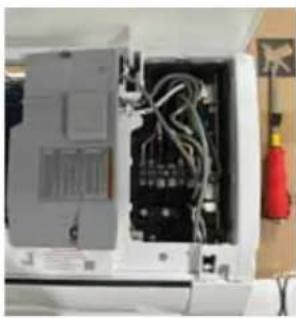
- Remove the electrical box cover.
natural_image
Close-up of a car's engine compartment with visible hoses and a green cylindrical component (no text or symbols)- Remove leak sensor.
natural_image
Close-up of a hand holding a green printed circuit board with wires and components (no visible text or symbols)- Pull out the PCB and unplug the refrigerant leak sensor from CN3.
Haier Ductless HVAC Limited Warranty
HaierAppliances.com
Please save your receipt showing the date of original purchase and the date of installation.
For the product models listed on Attachment 1 (the "Product"), this Standard Limited Warranty is provided to the Original Owner of the Product:
| For the Period of: | |
| 1 Year Remote Controller Warranty From the date of the original installation | If the Remote Controller proves to be defective due to improper workmanship and/or material for a period of one (1) year from the date of installation, Haier will provide a new or refurbished controller, as Haier's sole discretion. |
| 5 Year Limited Parts Warranty From the date of the original installation | If any parts should prove to be defective due to improper workmanship and/or material for a period of five (5) years from the date of installation, Haier will place any defective parts without charge for the part. Parts used for replacement may be new or refurbished parts, determined at Haier's sole discretion, and provided to your licensed HVAC technician installer. |
| 10 Year Registered Limited Parts Warranty From the date of the original installation(ONLINE REGISTRATION REQUIRED at HaierAppliances.com)MUST BE A RESIDENTIAL SINGLE FAMILY HOME | If any of the parts should prove defective due to improper workmanship and/or material for a period of ten (10) years from the date of installation, Haier will replace any defective parts without charge for the part. The replacement part is warranted for the remainder of the original ten (10) year warranty period. Parts used for replacement may be new or refurbished parts, determined at Haier'sx sole discretion, and provided to your licensed HVAC technician installer. This Registered Limited Parts Warranty requires online registration within sixty (60) days from the original date of installation or occupancy.NON-RESIDENTIAL/ COMMERCIAL APPLICATIONS ARE NOT ELIGIBLE FOR THIS REGISTERED LIMITED PARTS WARRANTY. |
LABOR NOT COVERED
These limited warranties DO NOT include labor or any other costs incurred for service, maintenance, repair, removing, replacing, installing, complying with local building or electrical codes, shipping or handling, replacement of the system, compressors or other parts.
EXCLUDED COMPONENTS
The following components are not covered by this warranty: cabinets, cabinet pieces, air filters, driers, refrigerant, refrigerant line sets, belts, wiring, fuses, oil nozzles, unit accessories and any parts not affecting unit operation.
WHAT IS THE DATE OF PURCHASE
The “Date of Purchase” is the date the Product is purchased by the Original Owner. The “Date of Installation” is the date that the original installation was completed, and all Product start-up procedures were properly completed and verified on the installer’s invoice. If the installation date cannot be verified, then the Date of Installation will either be sixty (60) days after the manufacture date, as determined by the Product’s serial number or thirty (30) days from the Date of Purchase. You should keep and be able to provide your original sales receipt from the installer as proof of the Date of Purchase and the Date of Installation. For new construction, the Date of Purchase will be the date of purchase of the residence by the Owner from the builder.
Haier Ductless HVAC Limited Warranty
WHO IS COVERED
Owner occupied: The “Original Owner” means the original owner (and his or her spouse) of a residential single family where the Product was originally installed.
Non-Owner occupied: The "Non-Owner occupied" is defined as a) single family or multi-family residential buildings that are not Owner Occupied, or b) light commercial applications, (such as office buildings, retail establishments, hotels/motels).
For Non-owner occupied, this limited warranty requires that the Product be installed and maintained annually by a licensed HVAC technician (proof of annual maintenance is required).
HOW CAN YOU GET SERVICE
Contact your licensed HVAC technician installer. All installation and service must be performed by a licensed HVAC technician. Failure to use a licensed HVAC technician for installation of this Product voids all warranty on this Product.
WHAT HAIER WILL NOT COVER:
- Improper service or installation.
• Damage in shipping. - Defects other than manufacturing defects than workmanship or materials).
- Damage from misuse, abuse, accident, alteration, lack of proper care and/or regular maintenance
- Damage resulting from floods, fires, wind, accidents or similar conditions.
- Product that was not installed or serviced by a licensed HVAC technician.
- Labor and related services for repair or installation of the Product.
- A product purchased from an unauthorized online retailer.
- Damage as a result of subjecting Product to an atmosphere with corrosives or high levels of particulates (such as soot, aerosols, fumes, grease).
- Modification, change or alteration of the equipment, except as directed in writing by Haier.
- Use of contaminated or refrigerant not compatible with the unit
- Operation with system components (indoor unit, outdoor unit, and refrigerant control devices) which are not an AHRI match or meet the specifications recommended by Haier.
• A Product sold and/or installed outside of the 50 United States, the District of Columbia, or Canada.
- Batteries for the controller and other accessories provided with the Product for installation (e.g., plastic hose).
- Normal maintenance, such as cleaning of coils, filters, and lubrication.
• For Product installed in Non-Owner Occupied (i.e., other applications, Product that has not been maintained annually by a licensed HVAC technician (proof required). - Damage caused by a used or unapproved component or part by Haier (e.g., a used and/or unapproved condenser lightning handler).
- Component or parts not provided by Haier.
- Product that has been moved from its original installation to a new residence or building.
- Accident, or neglect or unreasonable use or operation of the equipment including operation of electrical equipment at voltages other than the range specified on the unit nameplate (includes damages caused by brownouts).
- Damage to the product caused by accident, fire, floods or acts of God.
- Incidental or consequential damage caused by defect with this product.
Haier Ductless HVAC Limited Warranty
LEGAL RIGHTS
Some states and provinces do not allow warranty terms to be subject to registration. In those states and provinces, the 10 year Registered Limited Parts Warranty applies. In addition, if allowed by the law of the state or province where the Product is installed, the subsequent owners of the residence or building may have additional rights or longer warranty terms.
REGISTERED LIMITED PARTS WARRANTY COVERAGE REQUIREMENTS
• The unit is a Haier branded unit
• The unit is installed in a residential application
- The unit is properly registered at (HaierAppliances.com) within 60 days after the original date of installation or occupancy.
- The unit is part of a complete AHRI matched system and installed by a state certified or licensed contractor in accordance with the unit installation, operation, and maintenance instructions provided with the unit.
- Indoor and outdoor ductless units are covered only when they are branded Haier and are purchased and installed as a system along with a qualifying unit. (Third party coils are not covered).
• Installation is in compliance with applicable laws, regulations, codes, and ordinances.
- Unit was not ordered via the internet. Proof of purchase may be required.
EXCLUSION OF IMPLIED WARRANTIES
EXCEPT TO THE EXTENT PROHIBITED BY APPLICABLE LAW, THIS LIMITED WARRANTY IS EXCLUSIVE AND GIVEN IN LIEU OF ALL OTHER WARRANTIES, EXPRESS OR IMPLIED, INCLUDING BUT NOT LIMITED TO ANY IMPLIED WARRANTY OF MERCHANTABILITY AND FITNESS FOR A PARTICULAR PURPOSE.
EXCEPT TO THE EXTENT PROHIBITED BY APPLICABLE LAW, THIS LIMITED WARRANTY IS EXCLUSIVE AND GIVEN IN LIEU OF ALL OTHER WARRANTIES, EXPRESS OR IMPLIED, INCLUDING BUT NOT LIMITED TO ANY IMPLIED WARRANTY OF MERCHANTABILITY AND FITNESS FOR A PARTICULAR PURPOSE.
SOME STATES DO NOT ALLOW THE EXCLUSION OR LIMITATION OF INCIDENTAL OR CONSEQUENTIAL DAMAGES, OR ALLOW DISCLAIMERS OF IMPLIED WARRANTIES, SO THE ABOVE LIMITATIONS OR EXCLUSIONS MAY NOT APPLY TO THE CUSTOMER. THIS LIMITED WARRANTY GIVES THE CUSTOMER SPECIFIC LEGAL RIGHTS. CUSTOMERS MAY ALSO HAVE OTHER RIGHTS THAT VARY FROM STATE TO STATE.
The remedy provided in this warranty is exclusive and is granted in lieu of all other remedies. This warranty does not cover incidental or consequential damages. Some states and provinces do not allow the exclusion of incidental or consequential damages, so this limitation may not apply to you. Some states and provinces do not allow limitations on how long an implied warranty lasts, so this limitation may not apply to you. This warranty gives you specific legal rights and you may also have other rights which vary by state and province. This warranty covers Products within the 50 United States, the District of Columbia and Canada.
This warranty is provided by:
GE Appliances, a Haier company
Louisville, KY 40225
Haier Ductless HVAC Limited Warranty
For US Customers: This limited warranty is extended to the original purchaser for products purchased for home use within the USA. In Alaska and Hawaii, the limited warranty does not include the costs of shipping units. Some states do not allow the exclusion or limitation of incidental or consequential damages. This warranty gives you specific legal rights, and you may also have other rights which vary from state to state. To know what your legal rights are, consult your local or state consumer affairs office or your state's Attorney General.
Warrantor: GE Appliances, a Haier company
Louisville, KY 40225
ATTACHMENT 1
Product is defined as a Haier branded Duct less Split Units. The Product contains 2 sub-categories of goods: "Indoor and Outdoor Products" and "Selected Installation Products," which are further defined below: "Indoor and Outdoor Products" can further be identified by the following model number descriptions:, 1G^ , 2G^ , 3G^ , 4G^ , 5G^ , GA^ GS*, US*
Record Keeping
Thank you for purchasing this GE Appliances product. This installation manual will help you get the best performance from your new heat pump.
For future reference, record the model and serial number located on the label on the side of your air conditioner/heat pump, and the date of purchase. Staple your proof of purchase to this manual to aid in obtaining warranty service if needed.
To register your new GE Appliances Duct Free system, go to geappliancesairandwater.com and input the model/serial number information on this page.
Model number
Serial number
Date of purchase
TABLE DES MATIÈRES
CONTENU DE L'EMBALLAGE 25
INFORMATION DE SÉCURITÉ....26
CONDITIONS DE FONCTIONNEMENT 29
INSTRUCTIONS D'INSTALLATION 35
Étape 1 – Préparation .... 36
INSTRUCTIONS D'INSTALLATION
natural_image
Complex electronic circuit board layout with components and connectors (no readable text or symbols)INSTRUCTIONS D'INSTALLATION
natural_image
Diagram showing two mechanical or structural states with arrows indicating motion, no text or symbols presentPlaque de montage
flowchart
graph TD
    A["L1 WHITE"] --> B["COMMUNICATION"]
    C["L2 BLACK"] --> B
    D["Ground"] --> B
    E["1 (N)"] --> F["1 (N)"]
    G["2 (L)"] --> H["2 (L)"]
    I["3 (C)"] --> J["3 (C)"]
    K["G"] --> L["Ground"]
    M["PURPLE (N/C)"] --> N["Gray (COM)"]
    O["ORANGE (N/O)"] --> P["Switch"]
    Q["RED"] --> R["Black"]
    S["Outdoor"] --> T["1(N)"]
    S --> U["2(L)"]
    S --> V["3(C)"]
    S --> W["G"]
INSTRUCTIONS D'INSTALLATION
natural_image
Close-up of a white electronic device with a cable inserted, showing internal components and a red hand holding a tool (no visible text or symbols)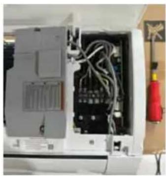
natural_image
Interior view of an open electrical enclosure with visible wiring and components (no text or symbols)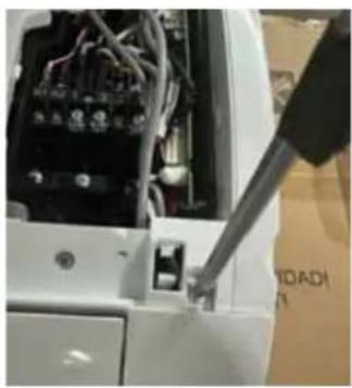
natural_image
Close-up of a white electronic device with visible wiring and components, being adjusted by a tool (no text or symbols)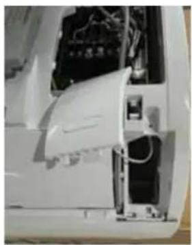
natural_image
Interior view of a white electronic device showing internal components and wiring (no visible text or symbols)natural_image
Close-up of a mechanical device with internal components and wiring (no visible text or symbols)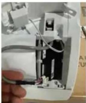
natural_image
Close-up of a hand holding a small electronic device with visible wiring and components (no text or symbols)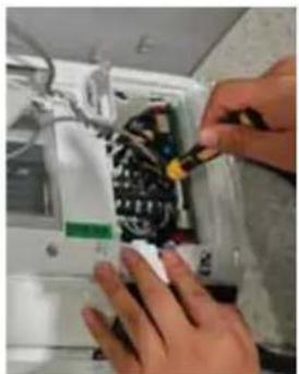
natural_image
Close-up of hands installing or adjusting a mechanical component with visible wiring and components (no text or symbols)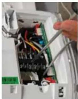
natural_image
Close-up of hands using a power tool to switch an open circuit board (no visible text or symbols)natural_image
Close-up of a hand holding a green electronic circuit board with wires and components (no visible text or symbols)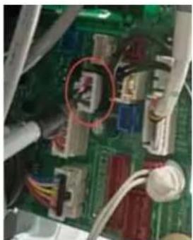
natural_image
Close-up of an electronic circuit board with visible components and wiring (no readable text or symbols)natural_image
Interior view of an air conditioner unit showing cooling panels and ventilation duct (no text or symbols visible)- Retirez le volet.
natural_image
Interior view of an air conditioner unit with visible cooling fins and ventilation ducts (no text or symbols)- Retirez les vis.
natural_image
Close-up of an air conditioner unit with visible cooling fins and ventilation duct (no text or symbols)natural_image
Close-up of a hand using a screwdriver to adjust or install components in a mechanical assembly (no visible text or symbols)natural_image
Close-up of hands holding a green circuit board with wires and components (no visible text or symbols)GE Appliances, a Haier company
Louisville, KY 40225
Garant : GE Appliances, a Haier company Louisville,
KY 40225
Tenue de dossiers
natural_image
Complex electronic circuit board layout with components and connectors (no readable text or symbols)flowchart
graph TD
    A["L1 WHITE"] --> B["COMMUNICATION"]
    C["L2 BLACK"] --> B
    D["Ground"] --> B
    E["1 (N)"] --> F["1 (N)"]
    G["2 (L)"] --> H["2 (L)"]
    I["3 (C)"] --> J["3 (C)"]
    K["G"] --> L["G"]
    M["PURPLE (N/C)"] --> N["ORANGE (N/O)"]
    O["RED BLACK"] --> P["Switch"]
    Q["GRAY (COM)"] --> P
    R["Outdoor"] --> S["1(N)"]
    R --> T["2(L)"]
    R --> U["3(C)"]
    R --> V["G"]
Paso 5 – Control Final
natural_image
Close-up of a hand using a screwdriver to adjust or install electronic components on a white device (no visible text or symbols)- Retire la tapa frontal.
natural_image
Interior view of an electronic device showing internal components and wiring (no visible text or symbols)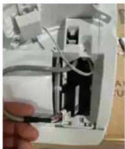
natural_image
Close-up of a hand holding an open electrical socket with visible wiring and components (no text or symbols)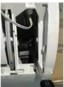
natural_image
Close-up of a mechanical device with internal components and wiring (no visible text or symbols)natural_image
Close-up of electrical wiring and components with no visible text or symbols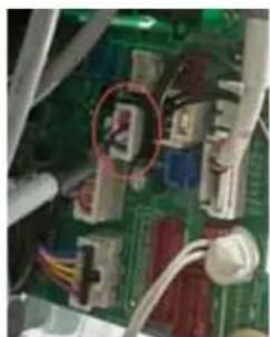
natural_image
Close-up of a green printed circuit board with visible wiring and components (no readable text or symbols)natural_image
Close-up of a white electronic device with visible wiring and a black tool inserted, no text or symbols present.natural_image
Interior view of a white electronic device showing internal components and wiring (no visible text or symbols)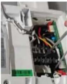
natural_image
Interior view of an electronic device with visible wiring and components (no readable text or symbols)
natural_image
Close-up of hands installing or repairing an electrical circuit board with wires (no visible text or symbols)natural_image
Interior view of an air conditioner unit with cooling fins and ventilation ducts (no visible text or symbols)- Retire la aleta.
natural_image
Interior view of a server rack with black panels and red indicator lights (no visible text or symbols)natural_image
Close-up of an air conditioner unit with visible cooling cover and ventilation slots (no text or symbols)natural_image
Close-up of a mechanical component with a green cylindrical part inserted, showing internal wiring and a tool (no visible text or symbols)natural_image
Close-up of a hand holding a green electronic circuit board with wires and components (no visible text or symbols)GE Appliances, a Haier company
Louisville, KY 40225
Garante: GE Appliances, a Haier company Louisville, KY 40225


- Duct less Single Zone with Highwall Indoor Unit
- TABLE OF CONTENTS
- PACKAGE CONTENTS
- IMPORTANT SAFETY INFORMATION
- WARNING
- RISK OF ELECTRIC SHOCK. Could cause injury or death.
- RISK OF FIRE. Could cause injury or death.
- ATTENTION
- READ AND SAVE THESE INSTRUCTIONS
- BEFORE YOU BEGIN
- Safety Awareness
- Unpacking Inspection
- Inspection on Installation Environment
- Safety Principles of Installation
- CAUTION
- Requirements for Operation, Service and Installation of Appliances Using Flammable Refrigerants
- General
- General (cont.)
- Qualification of workers
- Examples for such working procedures are:
- Information on servicing
- Information on servicing (cont.)
- Repairs to sealed components, intrinsically safe components
- Cabling
- Detection of flammable refrigerants
- NOTE: Examples of leak detection fluids are:
- Removal and evacuation
- Charging procedures
- Decommissioning
- Labeling
- Recovery
- Required Tools for Installation
- INSTALLATION INSTRUCTIONS
- MINIMUM CLEARANCES
- (Appearance may vary)
- Supplied by Installer
- Refrigerant Line Set: for sizing please refer to the Outdoor Unit Rating Plate
- IMPORTANT
- NOTE:
- Step 1 - Preparation
- Before installing the indoor unit, determine allowable room size 1 .
- If leak sensor is not needed or installed, make sure to flip dip switch 3-2 to OFF (see right picture).
- Step 1 - Preparation (cont.)
- Install the Leak Sensor.
- Capacity Adjustment (for GS06WP2BE\* models only)
- Step 2 - Installation of the Indoor Unit
- Select the Indoor location:
- Wall Brackets
- Step 2 - Installation of the Indoor Unit (Cont.)
- Install the Mounting Plate
- Install the Tubing
- Electrical Connections for the Indoor Unit
- Mount Indoor Unit to Mounting Plate
- Condensate Drainage Pipe
- To Remove the Indoor Unit
- Step 3 - Installation of the Outdoor Unit
- Step 4 - Safety Switch Control Wiring
- Step 5 - Final Check
- Explaining Operation to the End User
- Check Items for Test Run
- Verify Refrigerant Leak Sensor Function
- Software Notice
- QACT17\* wired controller (optional accessory)
- Refrigerant Leak Sensor Replacement Instructions
- Haier Ductless HVAC Limited Warranty
- HaierAppliances.com
- LABOR NOT COVERED
- EXCLUDED COMPONENTS
- WHAT IS THE DATE OF PURCHASE
- WHO IS COVERED
- HOW CAN YOU GET SERVICE
- WHAT HAIER WILL NOT COVER:
- LEGAL RIGHTS
- REGISTERED LIMITED PARTS WARRANTY COVERAGE REQUIREMENTS
- EXCLUSION OF IMPLIED WARRANTIES
- ATTACHMENT 1
- Record Keeping
- TABLE DES MATIÈRES
- INSTRUCTIONS D'INSTALLATION
- Tenue de dossiers
- Paso 5 – Control Final
Brand : HAIER
Model : QS24WP2BEB
Category : Air Conditioning