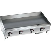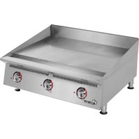
624TF - Grill plate STAR - Free user manual and instructions
Find the device manual for free 624TF STAR in PDF.


User questions about 624TF STAR
0 question about this device. Answer the ones you know or ask your own.
Ask a new question about this device
Download the instructions for your Grill plate in PDF format for free! Find your manual 624TF - STAR and take your electronic device back in hand. On this page are published all the documents necessary for the use of your device. 624TF by STAR.
USER MANUAL 624TF STAR
2M-Z16008 Rev. C 06/2019
natural_image
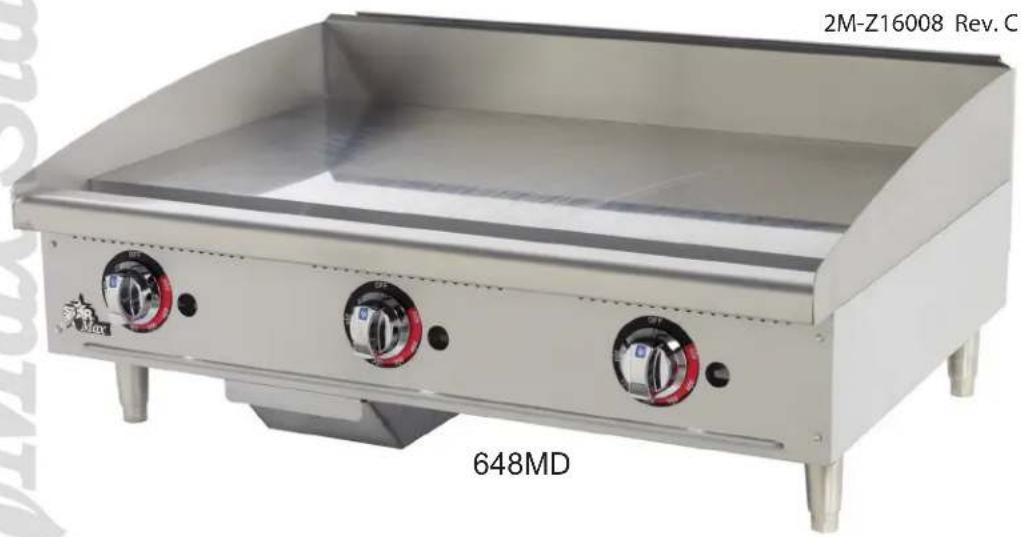
Exterior view of a stainless steel portable grating with three rotary controls (no text or symbols visible)
text_image
STAR®RETAIN THIS MANUAL FOR FUTURE REFERENCE
NOTICE
Using any part other than genuine Star factory supplied parts relieves the manufacturer of all liability.
Star reserves the right to change specifications and product design without notice. Such revisions do not entitle the buyer to corresponding changes, improvements, additions or replacements for previously purchased equipment.
Due to periodic changes in designs, methods, procedures, policies and regulations, the specifications contained in this sheet are subject to change without notice. While Star International Holdings Inc., Company exercises good faith efforts to provide information that is accurate, we are not responsible for errors or omissions in information provided or conclusions reached as a result of using the specifications. By using the information provided, the user assumes all risks in connection with such use.
MAINTENANCE AND REPAIRS
Contact your local authorized service agent for service or required maintenance.
Please record the model number, serial number, voltage and purchase date in the area below and have it ready when you call to ensure a faster service.
Model No.
Serial No.
Voltage
Purchase Date
Authorized Service Agent Listing
Reference the listing provided with the unit
or
for an updated listing go to:
Website: www.star-mfg.com
E-mail customerservice@star-mfg.com
Service Help Desk
Business 8:00 am to 4:30 p.m. Central Standard Time
Hours:
Telephone: (800) 264-7827
Fax: (314) 781-2714
E-mail customerservice@star-mfg.com
Website: www.star-mfg.com
Mailing Address: Star Manufacturing International Inc.
265 Hobson Street
Smithville, TN 37166
U.S.A
| SPECIFICATION | |||||||||
| Model C | Control BTU | Grid Area | Plate Thickness | Weight Dimensions | |||||
| Installed Shipped Width Depth Height | |||||||||
| 615 1 | 20,000 | 304 sq. in (1961 sq. cm) | 1" (2.54 cm) | 83 lb (37.6 kg) | 90 lb (4.8 kg) | 15" (38.1 cm) | 27.75" (70.5 cm) | 15.5" (39.4 cm) | |
| 624 2 | 56,600 | 498 sq in (3213 sq. cm) | 165 lb (74.8 kg) | 175 lb (79.4 kg) | 24" (61 cm) | ||||
| 636 3 | 84,900 | 747 sq in (4820 sq cm) | 247 lb (112 kg) | 262 lb (118.8 kg) | 36" (91.4 cm) | ||||
| 648 4 | 13,200 | 996 sq in (6426 sq cm) | 330 lb (144.7 kg) | 350 lb (158.8 kg) | 48" (122 cm) | ||||
| CONTROL TYPE | |
| MF Manual Control | |
| TF Thermostat Control | |
| TSPF Thermostat & Safety Pilot Control | |
| TCHSF Thermostat & Safety Pilot Control with Chrome Plate |
GENERAL INSTALLATION DATA
This equipment is designed and sold for commercial use only by personnel trained and experienced in its operation and is not sold for consumer use in and around the home nor for use directly by the general public in food service locations.
The Star-Max ^™ model griddles are equipped for use with the types of gas specified on the nameplate.
All units are shipped from the factory for use with natural gas. The unit can easily be converted for use on propane gas: See propane gas.
-IMPORTANT-
The installation of the Appliance should conform to the NATIONAL FUEL GAS CODE "ANSI Z223.1 - LATEST EDITION" AND ALL LOCAL GAS COMPANY RULES AND REGULATIONS.
IN CANADA INSTALLATION SHALL BE IN ACCORDANCE WITH THE CURRENT CAN/CGA-B149.1 NATURAL GAS INSTALLATION CODE OR CAN/CGA-B149.2 PROPANE INSTALLATION CODE AND LOCAL CODES WHERE APPLICABLE.
Improper installation, adjustment, alteration, service or maintenance can cause property damage, injury or death. Read the installation, operating and maintenance instructions thoroughly before installing or servicing the equipment.
For your safety, do not store or use gasoline or other flammable vapors and liquids in the vicinity of this or any other appliance. Keep the appliance area clear and free from combustibles.
This appliance, its pressure regulator and its individual shutoff valve must be disconnected from the gas supply piping system during any pressure testing of that system at test pressures in excess of 1/2 PSIG (3.45KPA).
This appliance and its pressure regulator must be isolated from the gas supply piping system by closing its individual manual shutoff valve during any pressure testing of the gas supply piping system at test pressures equal to or less than 1/2 PSIG (3.45KPA). For your protection, we recommend a qualified installing agency install this appliance. They should be familiar with gas installations and your local gas requirements. In any case, your gas company should be called to approve the final installation. In addition, there should be posted, in a prominent location, detailed instructions to be followed in the event the operator smells gas. Obtain the instructions from the local gas supplier.
For your safety, if you smell gas -
- Do not touch electrical switches.
- Extinguish any open flame.
- Immediately call your gas company.
KEEP THE APPLIANCE AREA FREE AND CLEAR FROM COMBUSTIBLES.
CLEARANCE
For use on non-combustible countertops only.
Combustible and non-combustible material must be at least 48" (120cm) from the top of the appliance and 6" (150mm) from the sides and back. Adequate clearance should also be provided for proper operation and servicing.
AIR SUPPLY
Make certain not to obstruct the flow of combustion and ventilation air. Provisions for adequate air supply must be furnished. The legs supplied with the unit must be installed. Make certain that air intake openings in the bottom of the appliance are not obstructed. They are essential for proper combustion and operation of the appliance.

EXHAUST CANOPY
It is essential that facilities be provided over the griddle to carry off fumes and gases. However, the unit should not be directly connected to a flue or stack.
LEVELING UNIT
This griddle is supplied with (4) feet which must be screwed into the legs attached to the body. Level unit by adjusting the (4) feet which have an adjustment of 1-3/4" (43.75mm) for accurate and perfect lineup with other units. After the griddle is in its final position, adjust the legs to create 1/8 inch slant from back to front on the griddle plate. This will allow grease to run into the grease gutter and provide the proper combustion air for the burners.
DO NOT INSTALL WITHOUT ATTACHING FEET - DO NOT REMOVE FEET.
GAS PIPING
Gas piping shall be of such size and so installed as to provide a supply of gas sufficient to meet the full gas input of the appliance. If the appliance is to be connected to existing piping, it shall be checked to determine if it has adequate capacity. Joint compound shall be used sparingly and only on the male threads of the pipe joints. Such compounds shall be resistant to the action of LP gases. WARNING: Any loose dirt or metal particles which are allowed to enter the gas lines on this appliance will damage the valve and affect its operation. When installing this appliance, all pipe and fittings must be free from loose dirt.
A convertible pressure regulator is provided with each griddle. It should be connected to the inlet pipe at the rear of the unit. The gas supply line is then connected to it. It is shipped set for 6" (15.24cm) water column manifold pressure for use with natural gas.
MANUAL SHUT-OFF VALVE
A manual shut-off valve should be installed upstream from the union and within 6 feet (1.829m) of this appliance.
GAS CONVERSION
This griddle is equipped with fixed orifice hoods and is shipped from the factory for use on either natural or LP gas. To convert to propane gas, install the burner orifice hoods, located in the grease drawer, (NAT orifices are not included) as follows:
- Remove front panel by removing screws located on the front and the bottom.
- Remove the burner(s) from the orifice hood(s). This is accomplished by removing the burner mounting screw(s) and sliding the burner(s) off the hood(s).
- Remove natural gas orifice hood(s) and install the propane hood(s) furnished.
- Reinstall burner(s).
- Reinstall front panel.
- Remove the slotted, or hex-threaded, plug from the pressure regulator. Invert the plug and re-install. The letters "LP or NAT" should now be visible on the plug. LP units the regulator is now set for 10" (25.4cm) water column, and NAT units the regulator is now set for 6" (15.24cm) water column.
- For LP Gas, set manifold pressure to 10" (25.4cm) water column. A 1/8" pipe plug on the supply pipe can be removed for attaching a pressure gauge.
CONNECTING GAS SUPPLY LINE
The gas inlet of the griddle is sealed at the factory to prevent entry of dirt. Do not remove this seal until the actual connection is made to the gas supply line.
CHECKING FOR GAS LEAKS
Soap and water solution or other material acceptable for the purpose shall be used in locating gas leakage. Matches, candle flame, or other sources of ignition shall not be used for this purpose. Check entire piping system for leaks.

LIGHTING INSTRUCTIONS
When griddle is first lit, it will smoke until the preservation oils and impurities are burned off.
- Turn off all knobs and pilot valves.
- Turn on main valve and light all pilots.
- Turn burner knobs to desired setting.
-
To turn burners off, turn knobs off.
-
Turn off main valve to unit and wait 5 minutes to clear gas.
NOTE: The griddles are equipped with standing pilots and should be lit immediately after the gas is turned on.
Pilot flames can be lit and observed through the front panel view ports. However, best access for lighting the pilot is from the bottom of the unit just behind the center wall.
LIGHTING INSTRUCTIONS (TCHSD and TSPD SERIES)
- Turn the control knobs to the "OFF" position.
If the gas valves have been on and gas has escaped through the burners, turn the burners "OFF" and wait 5 minutes to clear the gas.
- Turn the control knob to the "PILOT" position, depress and hold the knob while lighting the pilot. Hold the knob in for 60 seconds or until the pilot stays lit. (Repeat for all burner sections.)
- Depress and turn the control knob to the desired temperature.
- To turn the burners off turn the knob to the "PILOT" position.
- To turn off all gas turn the knob to the "OFF" position. The pilots must be relit to resume cooking settings.

PILOT LIGHT REGULATION
Adjust pilot light flames as small as possible, but high enough to light burner immediately when burner valve is turned on high.
ADJUSTING SAFETY PILOTS (SERIES TCHSF and TSPF ONLY)
A manual pilot valve is provided on the left side of the control to adjust the pilot flame. Adjust the pilot flame so that it is approximately 3/8 to 1/2" tall and a uniform cone shape.
BURNER ADJUSTMENT (MODELS MF ONLY)
- Remove the front panel.
- Turn burner valve knob to "HI" position.
- Close the air shutter on the front of the burner to give a soft blue flame having luminous tips and open to a point where the yellow tips disappear and a hard blue flame is obtained. Repeat for all burners.
BURNER ADJUSTMENT (MODELS TF, TCHSF and TSPF ONLY)
- Remove the front panel.
- Push dial in and set thermostat of one burner to 450^ F ( 229.9^ C).
- Close the air shutter on the front of the burner to give a soft blue flame having luminous tips and open to a point where the yellow tips disappear and a hard blue flame is obtained. Repeat for all burners.
BYPASS ADJUSTMENT ON THROTTLING CONTROL MODELS ONLY
Throttling control models have a minimum flame setting that provides a steady uniform flame across the burner when the control heat setting has been satisfied.
- Set the control at the maximum setting and wait for the burner flame to throttle back.
- Turn the dial to the 200 degree setting. A small steady flame should be visible on all the burner ports. This flame should be approximately 1/8" high.
- An adjustment screw is located either on the front or side of the control housing.
- Turn clockwise to decrease the flame height; turn counterclockwise to increase the flame
To ignite burners, turn burner valve knob to "HI" position. Each burner is controlled by an individual high-low, on-off valve. An infinite number of temperatures may be obtained by turning the burner valve knob to any position between high and low. For overnight shutdown, turn the valves to the "OFF" position.

SEASONING THE GRIDDLE HEATING SURFACE (NON-CHROMIUM SURFACES)
Clean the griddle surface thoroughly. After the griddle has been thoroughly cleaned, it should be seasoned to prevent food from sticking. Before using, and after each thorough scouring, season the griddle heating surface in the following manner:
- Turn the temperature control dial to 350^ F ( 174.9^ C).
- Using a clean cloth, not a spatula, spread a thin film of cooking oil over the griddle cooking surface. This film should remain on the hot griddle surface 1/2 hour.
- Remove excess oil and wipe clean.
- Apply another film of cooking oil over the hot cooking area for another 1/2 hour and again remove excess oil and wipe clean. The griddle surface should now be ready for use.
Even with careful seasoning food may, to some extent, stick to the griddle cooking surface until griddle plate is "broken in."
COOKING (MODELS TF, TCHSF and TSPF ONLY)
Set the thermostat dial knob to the temperature desired. After a short preheating period, the thermostat will automatically maintain the selected temperature.
GREASE PAN
A grease pan is located at the front and can be removed for cleaning from the front. This pan should be checked and emptied when necessary.
EXERCISE EXTREME CARE IN HANDLING THE GREASE PAN CONTAINING HOT GREASE.
GRIDDLE CARE (NON-CHROMIUM AREAS)
It takes very little time and effort to keep the griddle attractive and performing at top efficiency. If grease is permitted to accumulate, it will form a gummy cake and then carbonize into a hard substance which is extremely difficult to remove. To prevent this condition, the following suggestions for cleanliness should be followed:
- After each use, scrape the griddle with a scraper or flexible spatula to remove excess grease and food. A waste drawer is provided for the scrapings. If there is an accumulation of burned on grease and food, the griddle should be thoroughly scoured and reseasoned. Use pumice or griddle stone while the griddle is warm. DO NOT use steel wool because of the danger of steel slivers getting into the food.
- Daily-use a clean cloth and good non-abrasive cleaner to clean the stainless steel body of the griddle. Wipe the polished front with a soft cloth.
- At least once a day remove the waste drawer and wash in the same way as an ordinary cooking utensil. The drawer is removed by pulling forward, up and out.
GRIDDLE CARE (CHROMIUM AREAS)
It takes very little time and effort to keep this Chromium griddle surface sparkling clean and performing at top efficiency. DO NOT allow grease to accumulate as it will carbonize, becoming difficult to remove. To prevent this condition the following cleaning suggestions should be followed.
- Remove excess oil and food regularly with a 4" (100mm) wide Razor Sharp type scraper and wipe surface with a damp cloth.
- Following the scraping, a damp cloth and a non-silicated, non-abrasive, non-chlorinated cleaner such as Bon-Ami may be used to wipe surface clean, followed by wiping with clean wet cloth.
- Follow steps 2 and 3 from above section.
LIMITED EQUIPMENT WARRANTY
Star Manufacturing [as well as its subsidiaries, Toastmaster and Holman] warranties new products to be free from defects in material and/or workmanship for a period of one [1] year from the date of original installation, except as noted below. Defects that occur as a result of normal use, within the time period and limitations defined in this warranty, will at Star's discretion have the parts replaced or repaired by Star or a Star-authorized service agency.
THIS WARRANTY IS SUBJECT TO ALL LISTED CONDITIONS.
Repairs performed under this warranty are to be performed by a Star authorized service agency. Star will not be responsible for charges incurred or service performed by non-authorized repair agencies. In all cases, the nearest Star-authorized service agency must be used. Star will be responsible for normal labor charges incurred in the repair or replacement of a warranted product within 50 miles (80.5 km) of an authorized service agency. Time and expense charges for anything beyond that distance will be the responsibility of the owner. All labor will need to be performed during regular service hours. Any overtime premium will be charged to the owner. For all shipments outside the U.S.A. and Canada, please see the International Warranty for specific details. It is the responsibility of the owner to inspect and report any shipping damage claims, hidden or otherwise, promptly following delivery. No mileage or travel charges will be honored on any equipment that is deemed portable. In general, equipment with a cord and plug weighing less than 50 lb. (22.7 kg) is considered portable and should be taken or shipped to the closest authorized service agency, transportation prepaid.
PORTABLE EQUIPMENT EXAMPLES
- 514LL fryer
• 15MC and 18MCP hot food merchandisers
• QCS1, QCS2, and RCS2 toasters
• 16PD-A pretzel merchandisers
- Condiment dispensers except HPD- and SPD-series models
• All pop-up toasters
- All pastry display cabinets
- All heat lamps
• J4R popcorn machine
• 12NCPW and 15NCPW nacho merchandisers
• Nacho cheese warmers
except 11WLA-series models
• Specialty food warmers except 130R, 11RW, and 11WSA models
• All butter dispensers
- All nacho chip merchandisers
- All accessories
CONTACT
Should you require any assistance regarding the operation or maintenance of any Star equipment; write, phone, fax or email our service department. In all correspondence mention the model number and serial number of your unit, as well as the voltage or type of gas you are using.
Business hours are 8:00 a.m. to 4:30 p.m. Central Standard Time (CST)
Telephone: (800)-264-7827
Fax: (314)-781-2714
Email: Customerservice@star-mfg.com
www.star-mfg.com
WARRANTY EXCLUSIONS
THE FOLLOWING WILL NOT BE COVERED UNDER WARRANTY.
- Any product which has not been used, cleaned, maintained, or installed in accordance with the directions published in the appropriate installation sheet and/or owner's manual as well as national and local codes, including incorrect gas, electrical, or water connection. Star is not liable for any unit which has been mishandled, abused, misapplied, subjected to chlorides, harsh chemicals, or caustic cleaners, damaged from exposure to hard water, modified by unauthorized personnel, damaged by flood, fire, or other acts of nature [or God], or which have an altered or missing serial number.
- Installation, labor, and job checkouts, calibration of heat controls, air and gas burner/bypass/pilot adjustments, gas or electrical system checks, voltage and phase conversions, cleaning of equipment, or seasoning of griddle surface.
- Replacement of fuses or resetting of circuit breakers, safety controls, or reset buttons.
- Replacement of broken or damaged glass components, quartz heating elements, and light bulbs.
- Labor charges for all removable parts in gas charbroilers and hotplates, including but not limited to burners, grates, and radiants.
- Any labor charges incurred by delays, waiting time, or operating restrictions that hinder a service technician's ability to perform service.
- Replacement of items subject to normal wear or items that can easily be replaced during a daily cleaning routine, such as but not limited to knobs, bulbs, fuses, quartz heating elements, baskets, racks, and grease drawers.
- Components that should be replaced when damaged or worn, but have been field-repaired instead [eg. field-welded fry pots]
- Any loss of business or profits.
| PRODUCTS PARTS LABOR | ||
| Star-Ultra Max® fryers, griddles, charbroilers, and hotplates | 2 years | 2 years |
| Star-Max® fryers, griddles, charbroilers, and hotplates | 2 years | 2 years |
| Jetstar® popcorn poppers | 2 years | 2 years |
| StaltekTM roller grill coatings | 5 years | |
| Cast iron grates, burners; and burner shields | 180 days | |
| Star, Toastmaster, or Holman parts sold to repair equipment | 90 days | |
| Service First 1 year | ||
2M-Z16008 Star-Max Gas Griddles
text_image
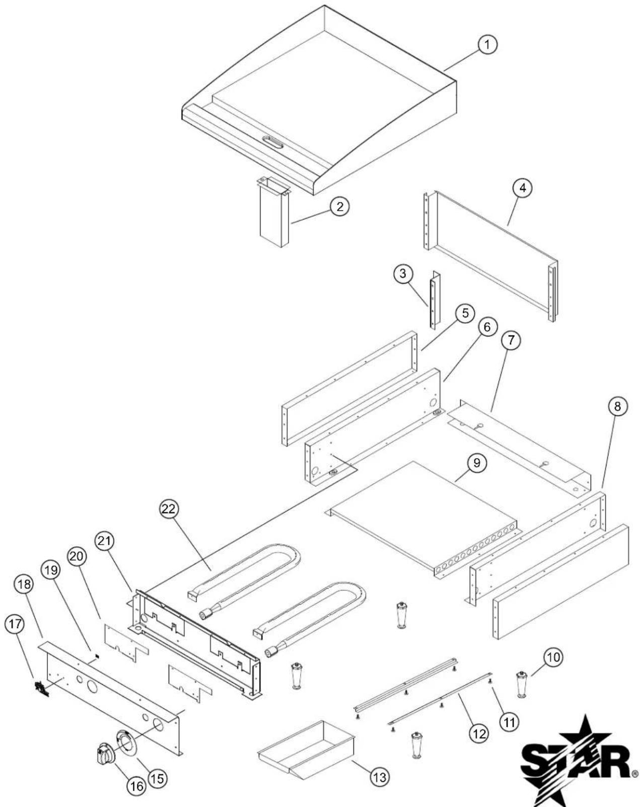
Exploded view diagram of a device with numbered components for identification and assembly reference.MODEL: 624MF,624TF, 624TSPF, 624TCHSF
STAR MANUFACTURING INTERNATIONAL, INC.
SK2598 REV.-06-12-12
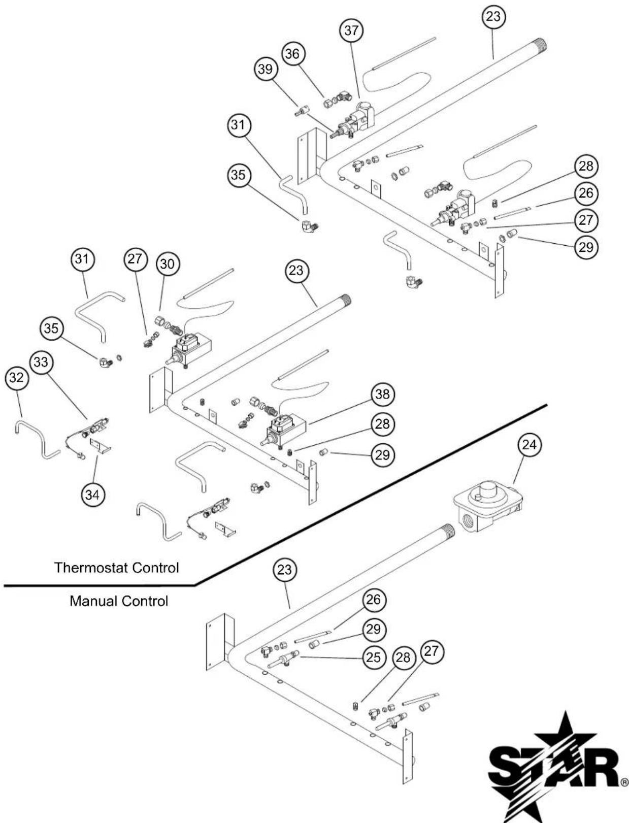
text_image
Thermostat Control Manual ControlMODEL 624MF,624TF, 624TSPF, 624TCHSF
STAR MANUFACTURING INTERNATIONAL, INC.
SK2599
Rev. A
| Fig No Part No Qty Description Application | ||||
| 1 | G3-615315 | CHSF | GRIDDLE PLATE ASSEMBLY | 615MF |
| G3-615316 615TF | ||||
| G3-624320 624MF | ||||
| G3-624321 624TCHSF | ||||
| G3-624322 624TF, 624TSPF | ||||
| G3-624323 DIVIDED PLATE ASSEMBLY 624MF-DIV | ||||
| G3-636316 | CHSF | GRIDDLE PLATE ASSEMBLY | 636MF | |
| G3-636317 636TF | ||||
| G3-636318 636TF, 636TSPF | ||||
| G3-648320 648MF | ||||
| G3-648321 648TCHSF | ||||
| G3-648322 648TF, 648TSPF | ||||
| G3-648323 648TF-TFR | ||||
| G3-648324 648TF-TFL | ||||
| 2 | G3-615304 | CHUTE ASSEMBLY | ALL 615 | |
| G3-624304 ALL 624, 636, 648 | ||||
| 3 | G5-Z4817 | FLUE DIVIDER | ALL 636, 648 | |
| 4 | G3-Z5906 | FLUE | 615MF, 615TF | |
| G5-Z4812 | 624MF, 624TF, 624TSPF, 624TCHSF | |||
| G5-Z4813 | 636MF, 636TF, 636TSPF, 636TCHSF | |||
| G5-Z4814 | 648MF, 648TF, 648TSPF, 648TCHSF | |||
| 5 | G3-Z5945 | SIDE PANEL | ALL | |
| 6 | G3-624302 | SIDE LINER ASSEMBLY LEFT | ALL | |
| 7 | G3-Z5951 | REAR PANEL | 615MF, 615TF | |
| G3-Z5953 | 624MF, 624TF, 624TSPF, 624TCHSF | |||
| G3-Z5955 | 636MF, 636TF, 636TSPF, 636TCHSF | |||
| G3-Z5957 | 648MF, 648TF, 648TSPF, 648TCHSF | |||
| 8 | G3-624303 | SIDE LINER ASSY RIGHT | ALL | |
| 9 | G3-Z5909 | BOTTOM | 615MF,615TF | |
| G3-Z5919 | 624MF, 624TF, 624TSPF, 624TCHSF | |||
| G3-Z5929 | 636MF, 636TF, 636TSPF, 636TCHSF | |||
| G3-Z5939 | 648MF, 648TF, 648TSPF, 648TCHSF | |||
| 10 | 2A-Z5942 | FOOT | ALL | |
| 11 | 2C-8823 | Various | SCREW #8 x 3/8 | ALL |
| 12 | G3-Z6036 | 2 | DRAWER SLIDE | ALL |
| 13 | G3-Y7046 | 1 | GREASE DRAWER | ALL |
| 15 | 2M-Z15449 | 1/2/3/4 | KNOB LABEL MAN LG | 615MF / 624MF / 636MF / 648MF |
| 2M-Z15450 | LABEL GAS T-STAT LG | 615TF / 624TF / 636TF / 648TF | ||
| 2M-Z16011 | 2/3/4 | KNOB LABEL GAS-TSTAT PILOT | 624TSPF/ 624TCHSF/ 636TSPF/ 636TCHSF/ 648TSPF/ 648TCHSF | |
| 16 | G3-Z15791 | 1/2/3/4 | KNOB ASSY LG GAS KEYR | 615TF / 624TF / 636TF / 648TF |
| I4-Z15484 | 2/3/4 | KNOB ASSY LG GAS KEYB | 615MF / 624MF / 636MF / 648MF | |
| 624TSPF / 636TSPF / 648TSPF | ||||
| 624TCHSF / 636TCHSF / 648TCHSF | ||||
IMPORTANT: WHEN ORDERING, SPECIFY VOLTAGE OR TYPE GAS DESIRED
INCLUDE MODEL AND SERIAL NUMBER
OF 3
PAGE 1
Some items are included for illustrative purposes only and in certain instances may not be available.
| Model: 615, 624, 636, 648 Star-Max Gas Griddles | ||||
| Fig No Part No Qty Description Application | ||||
| 17 2M-Z15804 1 STAR-MAX LOGO ALL | ||||
| 18 | G3-Z15797 | 1 FRONT PANEL | 615MF | |
| G3-Z15798 615TF | ||||
| G3-Z15799 624MF | ||||
| G3-Z15806 624TF, 624TSPF, 624TCHSF | ||||
| G3-Z15807 636MF | ||||
| G3-Z15808 636TF, 636TSPF, 636TCHSF | ||||
| G3-Z15809 648MF | ||||
| G3-Z15810 648TF, 648TSPF, 648TCHSF | ||||
| 19 2C-8477 | 3 CLIP .125 PO STL PHOS ALL | |||
| 20 | G3-Z5946 | 1/2/3/4 | BURNER COVER | ALL 615 / 624 / 636 / 648 |
| 21 | G3-Z5905 | 1 CENTER WALL | 615MF, 615TF | |
| G3-Z5915 | 624MF, 624TF, 624TSPF, 624TCHSF | |||
| G3-Z5925 | 636MF, 636TF, 636TSPF, 636TCHSF | |||
| G3-Z5935 | 648MF, 648TF, 648TSPF, 648TCHSF | |||
| 22 | 2F-Z5949 | 1/2/3/4 | BURNER | ALL 615 / 624 / 636 / 648 |
| 23 | 2K-Z5960 | 1 MANIFOLD | 615MF | |
| 2K-Z5961 | 615TF | |||
| 2K-Z5962 | 624MF, 624MFS | |||
| 2K-Z5963 | 624TF, 624TSPF, 624TCHSF | |||
| 2K-Z5964 | 636MF, 636MFS | |||
| 2K-Z5965 | 636TF, 636TSPF, 636TCHSF | |||
| 2K-Z5966 | 648MF, 648MFS | |||
| 2K-Z5967 | 648TF, 648TSPF, 648TCHSF | |||
| 24 | 2J-Z0792 | 1 | PRESSURE REGULATOR | NAT UNITS |
| H3-Z4557 | REGULATOR-GAS 3/4 NPT LP | LP UNITS | ||
| 25 | 2V-Y8832 | 1/2/3/4 | VALVE-MANUAL GAS | 615MF / 624MF / 636MF / 648MF |
| 26 2V-Z6647 1/2/3/4 | PILOT BURNER | 615MF / 624MF / 636MF / 648MF | ||
| 615TF / 624TF / 636TF / 648TF | ||||
| 27 | 2V-6671 | 1/2/3/4 | PILOT VALVE | ALL 615 / 624 / 636 / 648 |
| 28 2P-1453 | 1 | PIPE PLUG | 615MF, 624MF, 636MF, 648MF | |
| 615TF, 624TF, 636TF, 648TF | ||||
| 3/4/5 | 624TSPF / 636TSPF / 648TSPF | |||
| 624TCHSF / 636TCHSF / 648TCHSF | ||||
| 29 | 2A-Y1255 | 2/3/4 | ORIFICE PROPANE | 624 / 636 / 648 LP |
| 2A-Z4930 | 1/2/3/4 | ORIFICE #41, NAT | 624 / 636 / 648 NAT | |
| 30 2K-Z5968 | 2/3/4 FITTING 1/4 MPT X 3/8 CC | 624TSPF / 636TSPF / 648TSPF | ||
| 624TCHSF / 636TCHSF / 648TCHSF | ||||
| 31 2K-Z4921 | 2/3/4 | BURNER TUBE | 624TSPF / 636TSPF / 648TSPF | |
| 624TCHSF / 636TCHSF / 648TCHSF | ||||
| 1/2/3/4 | 615TF / 624TF / 636TF / 648TF | |||
| 32 2K-Z6081 | 2/3/4 PILOT TUBE | 624TSPF / 636TSPF / 648TSPF | ||
| 624TCHSF / 636TCHSF / 648TCHSF | ||||
IMPORTANT: WHEN ORDERING, SPECIFY VOLTAGE OR TYPE GAS DESIRED
INCLUDE MODEL AND SERIAL NUMBER
OF 3
PAGE 2
Some items are included for illustrative purposes only and in certain instances may not be available.
| Model: 615, 624, 636, 648 Star-Max Gas Griddles | ||||
| Fig No | Part No Qty Description | Application | ||
| 33 2J- | Z0804 2/3/4 THERMOCOUPLE-PILOT | 624TSPF / 636TSPF / 648TSPF | ||
| 624TCHSF / 636TCHSF / 648TCHSF | ||||
| 34 G3- | -Z6124 2/3/4 PILOT BRACKET | 624TSPF / 636TSPF / 648TSPF | ||
| 624TCHSF / 636TCHSF / 648TCHSF | ||||
| 35 2A- | 9369 | 1/2/3/4 | ORIFICE FITTING | 615TF / 624TF / 636TF / 648TF |
| 2/3/4 | 624TSPF / 636TSPF / 648TSPF | |||
| 624TCHSF / 636TCHSF / 648TCHSF | ||||
| 36 | 2K-Y7111 | 1/2/3/4 | ELBOW 1/4 MBT X 3/8 CC | 615TF / 624TF / 636TF / 648TF |
| 37 | 2T-Z4293 | 1/2/3/4 | THERMOSTAT | 615TF / 624TF / 636TF / 648TF |
| 38 2J- | Z5959 2/3/4 COMBINATION | CONTROL | 624TSPF / 636TSPF / 648TSPF | |
| 624TCHSF / 636TCHSF / 648TCHSF | ||||
| 39 | 2T-Y7590 | 1/2/3/4 | STEM-T-STAT | 615TF / 624TF / 636TF / 648TF |
ENTRETIEN DU GRIL (SURFACES CHROMÉES)
INSTRUCTIONS D'ALLUMAGE
ROBINET D'ARRÊT MANUEL
2M-Z16008 Rev. A 8/08/12
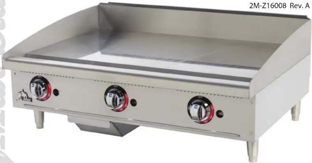
natural_image
Exterior view of a stainless steel grating with three rotary valves (no text or symbols visible)