AB12SC2VHA - Air Conditioning HAIER - Free user manual and instructions
Find the device manual for free AB12SC2VHA HAIER in PDF.

User questions about AB12SC2VHA HAIER
0 question about this device. Answer the ones you know or ask your own.
Ask a new question about this device
Download the instructions for your Air Conditioning in PDF format for free! Find your manual AB12SC2VHA - HAIER and take your electronic device back in hand. On this page are published all the documents necessary for the use of your device. AB12SC2VHA by HAIER.
USER MANUAL AB12SC2VHA HAIER
Installation Instructions
Compact Cassette
natural_image
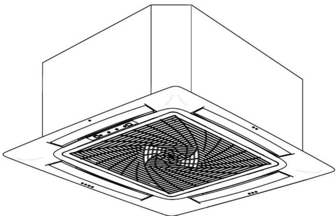
Isometric line drawing of a ceiling fan installation with no text or symbolsDesign may vary by model number.
This manual contains installation instructions for Compact Cassette indoor units. For the FlexFit ^™ series using other style indoor units, refer to the Installation Manual supplied with the indoor unit.
Table of Contents
IMPORTANT SAFETY INFORMATION....4
INSTALLATION INSTRUCTIONS 5
Step 1....9
Step 2....10
Step 3....12
Step 4 12
LIMITED WARRANTY....13
IMPORTANT SAFETY INFORMATION READ ALL INSTRUCTIONS BEFORE USING THE APPLIANCE
WARNING
For your safety, the information in this manual must be followed to minimize the risk of
fire, electric shock, or personal injury.
- Use this equipment only for its intended purpose as described in this manual.
- This heat pump must be properly installed in accordance with these instructions before it is used.
- All wiring should be rated for the amperage value listed on the rating plate. Use only copper wiring.
- All electrical work must be completed by a qualified electrician and completed in accordance with local and national building codes.
- Any servicing must be performed by a qualified individual.
For any service which requires entry into the refrigerant sealed system, Federal regulations require that the work is performed by a technician having a Class II or Universal certification.
- All air conditioners contain refrigerants, which under federal law must be removed prior to product disposal. If you are getting rid of an old product with refrigerants, check with the company handling disposal.
- These R-410A heat pumps systems require that contractors and technicians use tools, equipment and safety standards approved for use with this refrigerant. DO NOT use equipment certified for R22 refrigerant only.
WARNING
RISK OF ELECTRIC SHOCK. Could cause injury or death.
- An adequate ground is essential before connecting the power supply.
- Disconnect all connected electric power supplies before servicing.
- Repair or replace immediately all electrical wiring that has become frayed or otherwise damaged. Do not use wiring that shows cracks or abrasion damage along its length or at either end.
WARNING
RISK OF FIRE. Could cause injury or death.
- Do not store or use combustible materials, gasoline or other flammable vapors or liquids in the vicinity of this or any other appliance.
READ AND SAVE THESE INSTRUCTIONS
FOR MORE HELP, VISIT HAIERAPPLIANCES.COM/DUCTLESS OR GEAPPLIANCES.COM/DUCTLESS
BEFORE YOU BEGIN
Read these instructions completely and carefully.
- IMPORTANT — Save these
instructions for local inspector's use. - IMPORTANT — Observe all governing codes and ordinances.
- Notetoinstaller – Be sure to leave these instructions with the owner.
- Note to consumer – Keep these instructions for future reference.
- Skill level – A licensed certified technician (to handle refrigerant R-410A, recovery, etc) and a qualified electrician are required for installation and service of this split heat pump system.
- Use team lift for mounting the ducted unit.
- Proper installation is the responsibility of the installer.
- Product failure due to improper installation is not covered under the limited warranty.
- For personal safety, this system must be properly grounded.
- Protective devices (fuses or circuit breakers) acceptable for installation are specified on the nameplate of each unit.
- Make sure to avoid wiring or plumbing inside the wall when installing.
CAUTION
- Aluminum building wiring may present special problems - consult a qualified electrician.
- When the unit is in the STOP position, there is still voltage to the electrical controls.
Required Tools for Installation
- 17mm, 22mm, 26mm or Adjustable Wrench
• #2 Phillips Screwdriver - Drill
- 45^ Flaring Tool
- Hex Wrench
- Hole Saw 2 34
- Level
- Manifold Gauge
- Measuring Tape
- Micron Gauge
-
Mini-Split Adapter (5/16"F to 1/4"M)
-
Nitrogen*
- Pipe Cutter
- Razor Knife
- Reamer
- Sealant, non-expanding (for lineset hole)
- Soap/water solution or gas leakage detector
- Stud Finder
- Torque Wrench
- Vacuum Pump
- Wire Strippers
Supplied with Unit
- Condensate connecting tube
- Clamp
-
Flare nuts
-
YR-HG remote (batteries included)
- Insulation
- Mounting Template
Supplied by Installer
| Model Liquid (inch) | Vapor (inch) | |
| AB09SC2VHA 1/4 | 3/8 | |
| AB12SC2VHA 1/4 | 3/8 | |
| AB18SC2VHA 1/4 | 1/2 |
• Insulated copper tubing
- 14/4 (14 gauge – 4 conductor) stranded copper cable
• 3/4 inch PVC for condensate
• Insulation for condensate drain
• 3/8 threaded rod, washers and nuts
- 410A Refrigerant
Installation Instructions: Introduction and Overview
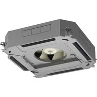
Cassette Product Information
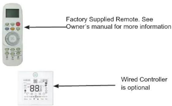
The Cassette Indoor Air Handler ships consists of a cassette assembly and operational louver. The Cassette Indoor Unit is operated via a factory supplied remote control. A wired controller is optional.
The Cassette unit will install between standard dropped ceiling grids. It is mounted using threaded rods that fit into brackets that are located at all four corners of the cassette assembly.
The Cassette unit receives 230 volt line voltage from a connection at the outdoor condensing unit. There is no requirement for independent line voltage connections.
The cassette unit has a built in condensate pump and associated float switch that manages the operation of the condensate pump. A flexible hose is included with the Cassette unit. This hose connects the cassette condensate drain outlet to the buildings condensate drain system.
The motorized louver is controlled via the remote control. The louver has indicator lights that communicate function and diagnostic information to the user and service technician.
Factory provided insulating tape is included with the cassette unit. This tape should be placed over the refrigerant piping connections at the indoor unit to prevent sweating.
text_image
Factory Supplied Remote. See Owner's manual for more information Wired Controller is optionalCompact Cassette (2'X2') Unit Specifications
| Indoor AB09SC2VHA AB12SC2VHA AB18SC2VHA | |||
| Rated Cooling Capacity Btu/hr 9,000 12,000 18,000 | |||
| Rated Heating Capacity Btu/hr 10,000 13,000 19,000 | |||
| Voltage, Cycle, Phase V/Hz/- 208-230/60/1 208-230/60/1 208-230/60/1 | |||
| Fan Speed Stages 5+Auto 5+Auto 5+Auto | |||
| Airflow (Turbo/High/Med/Low/ Quiet) CFM | 410/365/305/265/205 | 410/365/305/265/205 | 470/410/365/295/252 |
| Motor Speed (Turbo/High/Med/Low/ Quiet) RPM | 750/690/620/560/500 | 750/690/620/560/500 | 830/750/690/610/550 |
| Indoor Sound Level dB (Turbo/High/ Med/Low/Quiet) | 42/40/36/32/25 | 42/40/36/32/25 | 45/42/40/36/32 |
| Panel Model PB-700KB (Haier) / ACP22CWA (GE) | PB-700KB (Haier) / ACP22CWA (GE) | PB-700KB (Haier) / ACP22CWA (GE) | |
| Chassis Dimension: Height in (mm) | 10 1/4 (260) | 10 1/4 (260) | 10 1/4 (260) |
| Chassis Dimension: Width in (mm) | 22 7/16(570) | 22 7/16(570) | 22 7/16(570) |
| Chassis Dimension: Depth in (mm) | 22 7/16(570) | 22 7/16(570) | 22 7/16(570) |
| Panel Dimension: Height in (mm) | 2 3/8 (60) | 2 3/8 (60) 2 3/8 (60) | |
| Panel Dimension: Width in (mm) | 27 9/16 (700) | 27 9/16 (700) | 27 9/16 (700) |
| Panel Dimension: Depth in (mm) | 27 9/16 (700) | 27 9/16 (700) | 27 9/16 (700) |
| Weight (Ship/Net)- lbs (kg) | 46.3/37.5 (21/17) | 48.5/40.8 (22/18.5) | 48.5/40.8 (22/18.5) |
| Connections Flare | Flare | Flare | |
| Liquid O.D. in | 1/4 | 1/4 | 1/4 |
| Suction O.D. in | 3/8 | 3/8 | 1/2 |
| Drainpipe Size O.D. in | 1 1/4 | 1 1/4 | 1 1/4 |
| Internal Condensate Pump | Standard | Standard | Standard |
| Max. Drain-Lift height in(mm) | 47 3/16(1,200) | 47 3/16(1,200) | 47 3/16(1,200) |
Installation Instructions: Introduction and Overview
Fresh Air Intake Option
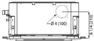
The cassette has a marked area to cut out if outside air is desired. The piping connection should be made with a 4 inch diameter pipe. Outside air should be pre-filtered prior to entry into the cassette.
text_image
Ø 4 (100) 8 1/4 (210)Condensate Handling
The Cassette unit has a built in condensate pump and water level safety switch. There is no option for gravity drain. The condensate pump is rated to lift water up to 47 3/16" from the point of discharge on the cassette assembly.
natural_image
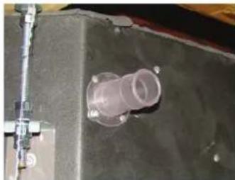
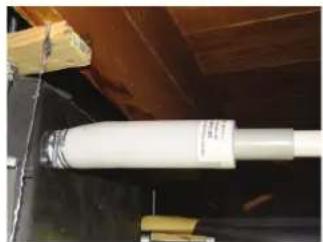
Close-up of a mechanical component with a translucent cylindrical fitting and mounting bracket (no visible text or symbols)The cassette unit comes with a grey connection hose with clamp. This hose is connected to the cassette assembly discharge hose port. The other end of the hose is sized to accept 3/4 "PVC piping. Recommended condensate piping configurations are shown here:
natural_image
Close-up of a white cylindrical object mounted on a dark surface, with no visible text or symbols.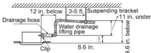
text_image
12 in. below 3-5 ft. Suspended bracket Drainage hose Water drainage lifting pipe 11 in. under Clip 8.6 in. 9.6 in. belowElectrical Power
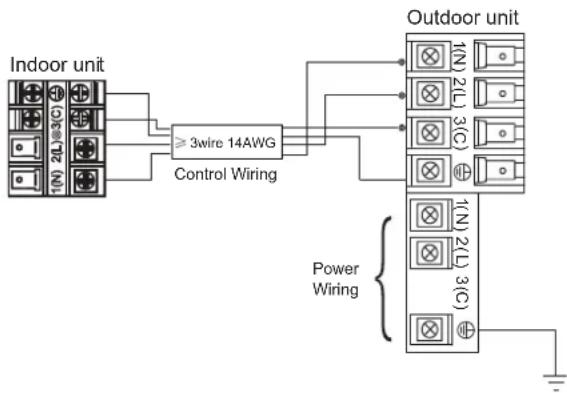
Follow all local codes and regulations when installing electrical wiring.
Route required electrical power to area where the Cassette unit is to be located. Maintain at least a 10 foot separation between TV, Radio or any communication wiring and the power to the indoor unit.
14 Gauge stranded copper wire should be used to make the electrical connection and communication link between indoor and outdoor units.
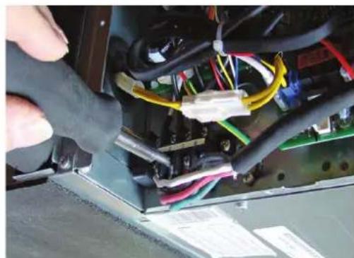
The wiring is connected at the indoor unit electrical terminal blocks screws 1, 2, 3 and ground. There should be no splices in the wires between the indoor and outdoor units as these serve as communication signal wires and electrical power connections. Any accessory added to shut off power to the indoor section should break the Number 2 terminal only.
natural_image
Close-up of a hand using a tool to adjust or install electronic components with visible wiring and connectors (no text or symbols)Air Delivery Clearances
Make certain to maintain proper clearances around the cassette as specified in the installation instructions. Standard clearances for cassette air handlers require 5 feet of clearance in each direction. There should be 8 feet of clearance from the face of the cassette grille to the floor. Inadequate clearances can cause system freezing and temperature control problems.
Service and Maintenance Clearances
Make sure there are adequate clearances for future maintenance and service. Allow enough room to access the condensate pump assembly and the electrical control box.
MINIMUM CLEARANCES (Appearance may vary)
This picture is for reference only. Your product may look different.
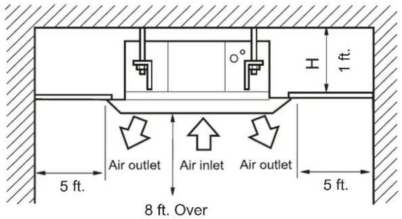
text_image
1 ft. Air outlet Air inlet Air outlet 5 ft. 8 ft. Over 5 ft.Step 1 - Preparation
A. Procedure for selecting the location:
- Place above the ceiling where you have enough space to position the unit.
- Place where the drainage pipe can be properly positioned.
- Place where the inlet and outlet air of the indoor unit will not be blocked.
- Do not install the unit in a place with heavy oil or moisture (e.g. - kitchens and workshops)
- Do not install in a location with destructive gas (such as sulfuric acid gas) or pungent gas (thinner and gasoline) are used or stored.
- Choose a place solid enough to bear the weight and vibration of the unit and where the operation
noise will not be amplified.
• Install where there are no expensive items like a television or piano below the indoor unit.
- Leave enough space for maintenance.
• Install at least 3 ft. away from televisions and radios to avoid interference.
NOTES:
- R-410A refrigerant is a safe, nontoxic and nonflammable refrigerant. However, if there is a concern about a dangerous level of refrigerant concentration in the case of refrigerant leakage, add extra ventilation.
B. Threaded Rod Mounting Information:
The Cassette unit should be mounted to the building structure using threaded rods. The threaded rods should have washers and nuts to allow the height and level of the cassette to be adjusted.
The threaded rods and attachment brackets are field supplied items. The materials required for mounting to the brackets on the cassette assembly include:
• 4-3/8" Threaded Rods
• 4- Mounting Brackets
- 8-Washers
• 8- Nuts (Double nut the assembly as shown)
natural_image
Interior view of a ceiling-mounted industrial or mechanical assembly with transparent structural beams and internal components (no visible text or symbols)Step 2 - Installation of the Cassette Unit
A. Use supplied cardboard template to locate center point of cassette for mounting. Use a plumb bob and string to position cassette by referencing center hole of template. Mark the mounting positions of the threaded rods using the guides on the cardboard template.
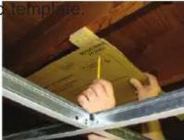
text_image
template.B. Install threaded rods to structure using appropriate fasteners.
natural_image
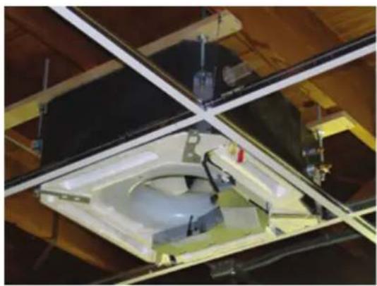
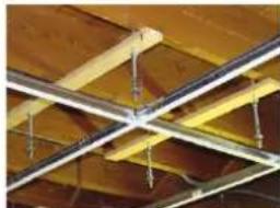
Close-up of ceiling beams and structural beams with diagonal braces (no text or symbols visible)C. Lift the cassette and position the threaded rods into the 4 mounting clips on each corner of the cassette unit.
natural_image
Interior view of a mechanical assembly with intersecting beams and central components (no visible text or symbols)One Inch Recess:
1 inch recess between ceiling surface ad bottom of unit without panel on.
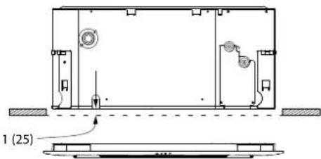
text_image
1 (25)D. Install threaded rods to structure using appropriate fasteners.
natural_image
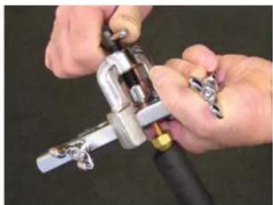
Close-up of hands using a tool to adjust or install a mechanical component (no visible text or symbols)E. Prior to routing the refrigerant lines to the unit, install the supplied flare nuts onto the refrigerator lines. Using an R-410 flaring tool, flare the refrigerant lines. Remove the caps attached to the ends of the refrigerant line connections at the cassette. A nitrogen charge will leak out.
Using a torque wrench, torque the fittings to the proper specifications. (See outdoor Unit Section for flare torque settings.)
natural_image
Close-up of hands using a mechanical clamp or tool to adjust a metal clamp (no text or symbols visible)
natural_image
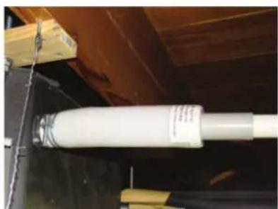
Close-up of industrial machinery components with no visible text or symbolsF. Connect the grey flexible drain hose supplied with the cassette unit to the condensate pump discharge pipe of the cassette. Tighten the clamp securely. Using the 3/4" PVC, connect the flexible hose to the building's condensate drain system.
natural_image
Close-up of a white cylindrical object mounted on a dark surface, with wooden beams and yellow tape visible (no text or symbols)Step 2 - Installation of the Indoor Unit (Cont.)
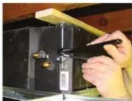
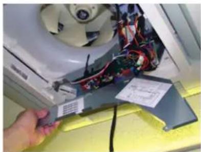
G. Remove the electrical box cover. Remove the rubber grommet and insert a 1/2 inch electrical connector and reducing washer. Route electrical wiring into cassette unit. Connect to wire terminas as indicated in schematic drawing. (USE 14 AWG stranded copper wire only.)
natural_image
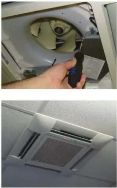
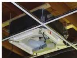
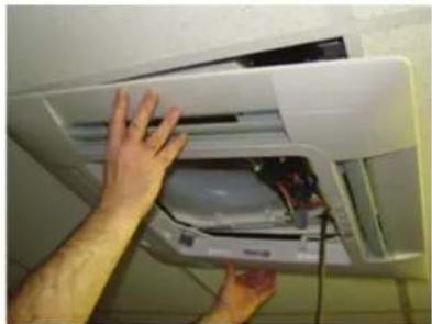
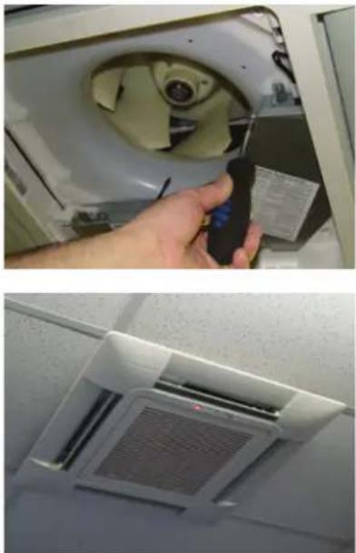
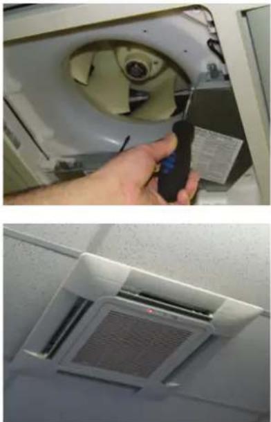
Close-up of a hand inserting electronic components into a white appliance (no visible text or symbols)H. Connect Grille assembly to cassette assembly. Connect wires from louver to the harness on the cassette assembly. There are two wire connections. (See photo for connections.) Secure louver with four screws.
Reinstall electrical box cover. Install return air grille into louver assembly.
Installation is now complete.
natural_image
Person installing or adjusting a white air conditioner unit with visible wiring and components (no text or symbols)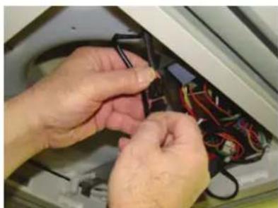
natural_image
Close-up of hands installing or adjusting a black cable with wires inside an open appliance (no visible text or symbols)H (cont.).
natural_image
Two-panel image showing a hand inserting a device into a fan-shaped device and a clean air vent (no text or symbols visible)Step 3 - Electrical Connections
Electrical connections indoor and outdoor units
14 AWG Stranded Copper Wire Only. (Central Controller Not Used)
Maintain 10 feet of separation between TV and any Radio wiring.
flowchart
graph TD
    A["Indoor unit"] --> B["≥3wire 14AWG Control Wiring"]
    B --> C["Outdoor unit"]
    D["Power Wiring"] --> E["1(N) 2(L) 3(C)"]
    D --> F["1(N) 2(L) 3(C)"]
Step 4 - Leak Testing and Evacuation
Refer to the outdoor section Installation Manual for the recommended procedure.
For the product models listed on Attachment 1 (the "Product"), this Standard Limited Warranty is provided to the Original Owner of the Product:
| For The Period Of: GE Appliances, a Haier company Will Replace: | |
| 5 year limited parts warrantyFrom the date of the original purchase | This limited warranty cover all defects in workmanship or material for the mechanical and electrical parts contained in the Product (“Defective Parts”) for a period of 5 years from the Date of Purchase. Haier will provide new or refurbished parts, or a replacement for all or part of the unit, at its sole discretion, to your licensed HVAC technician installer. This warranty also covers all defects in workmanship or material for the unit controller for a period of 1 year. The remote controller is covered by 1-year accessory warranty. The ductless system is covered by standard warranty. Haier will provide a new or refurbished controller, at its sole discretion. |
| 7 year compressor warranty from the date of the original purchase | The compressor contained in this product is warranted for a period of 7 years from the Date of Purchase. Haier will provide a new or refurbished compressor, or a replacement for all or part of the unit, at its sole discretion, to your licensed HVAC technician installer. |
WHAT IS THE DATE OF PURCHASE
The “Date of Purchase” is the date that the original installation is complete and all product start-up procedures have been properly completed and verified by the installer's invoice. If the installation date cannot be verified, then the Date of Purchase will be sixty (60) days after the manufacture date, as determined by the Product's serial number. You should keep and be able to provide your original sales receipt from the installer as proof of the Date of Purchase. In new construction, the Date of Purchase will be the date the owner purchased the residence from the builder.
WHO IS COVERED
Owner occupied: The “Original Owner” of this product, which means the original owner (and his or her spouse) of the residence where the Product was originally installed. Subject to the law of the state or province where the Product is installed, this warranty is not transferable to subsequent owners or if the product is moved to a different residence after the initial installation. Non-owner occupied: This limited warranty is provided for product 1) installed in a) single family or multi-family non-owner occupied residential buildings, or b) non-industrial commercial applications, (such as office buildings, retail establishments, hotels/motels) where the product is not subjected to an atmosphere with corrosives or high levels of particulates (such as soot, aerosols, fumes, grease), and 2) if the product is maintained annually by a licensed HVAC technician (proof of annual maintenance is required). The “Original Owner” of the product, means the original owner of the building where the product was originally installed. For new construction, the purchaser of the building from the builder will also be considered an original owner. This warranty is not transferable to subsequent owners or if the product is moved to a different location after the initial installation.
HOW CAN YOU GET SERVICE
Contact your licensed HVAC technician installer. All installation and service must be performed by a licensed HVAC technician. Failure to use a licensed HVAC technician for installation of this Product voids all warranty on this Product..
THIS WARRANTY DOES NOT COVER
- Damage from improper installation.
- Damage in shipping.
- Defects other than from manufacturing (i.e., workmanship or materials).
- Damage from misuse, abuse, accident, alteration, lack of proper care and/or regular maintenance, or incorrect electrical voltage or current.
- Damage resulting from floods, fires, wind, lightning, accidents or similar conditions.
- Damage from installation or other services performed by other than a licensed HVAC technician.
- Labor and related services for repair or installation of the Product.
• A Product purchased from an online retailer.
• Damage as a result of subjecting Product to an
atmosphere with corrosives or high levels of particulates (such as soot, aerosols, fumes, grease).
- A Product sold and/or installed outside of the 50 United States, the District of Columbia, or Canada.
- Batteries for the controller and other accessories provided with the Product for installation (e.g., plastic hose).
- Normal maintenance, such as cleaning of coils, cleaning filters, and lubrication.
- For Product installed in non-owner occupied applications, Product that has not been maintained annually by a licensed HVAC technician (proof required).
10 YEAR STANDARD REGISTERED LIMITED WARRANTY
All “Indoor and Outdoor Products,” identified in Attachment 1, registered by the installer or the Original Owner within 60 days of the Date of Purchase shall receive a Standard Registered Limited Warranty, which shall be identical to the Standard Base Warranty, except that the Limited Parts Warranty shall be for a term of 10 Years and the Limited Compressor Warranty shall be for a term of 10 years. All Product not registered within 60 days of the Date of Purchase shall be subject to the Standard Base Warranty. Some states and provinces do not allow warranty terms to be subject to registration; in those states and provinces the longer terms for Limited Parts Warranty and the Limited Compressor Warranty apply.
THIS LIMITED WARRANTY IS GIVEN IN LIEU OF ALL OTHER WARRANTIES, EXPRESS OR IMPLIED, INCLUDING THE WARRANTIES OF MERCHANTABILITY AND FITNESS FOR A PARTICULAR PURPOSE.
The remedy provided in this warranty is exclusive and is granted in lieu of all other remedies. This warranty does not cover incidental or consequential damages. Some states and provinces do not allow the exclusion of incidental or consequential damages, so this limitation may not apply to you. Some states and provinces do not allow limitations on how long an implied warranty lasts, so this limitation may not apply to you. This warranty gives you specific legal rights and you may also have other rights which vary by state and province. This warranty covers units within the 50 United States, the District of Columbia and Canada. This warranty it provided by GE Appliances a Haier company, Louisville, KY 40225.
ATTACHMENT 1
The “Product” is defined as Haier brand Ductless Split Units. The “Product” contains 2 sub-categories of goods: “Indoor and Outdoor Products” and “Selected Installation Products,” which are further defined below: “Indoor and Outdoor Products” can further be identified by the following model number descriptions: 1U*, 2U*, 3U*, 4U*, AB*, AD*, AL*, AM*, AW*, AF*, MVA* MVH* “Selected Installation Products,” identified by the following model number descriptions: PB-* FQG-* , AH1-* , MS1-* and MS3-*
Table des matières
CONSIGNES DE SÉCURITÉ IMPORTANTES....16
INSTRUCTIONS D'INSTALLATION 17
Étape 1....21
Étape 2....22
Étape 3....24
Étape 4 24
GARANTIE LIMITÉE 25
CONSIGNES DE SÉCURITÉ IMPORTANTES LISEZ TOUTES LES INSTRUCTIONS AVANT D'UTILISER L'APPAREIL
AVERTISSEMENT
natural_image
Close-up of a metallic pipe fitting mounted on a dark metal frame, with no visible text or symbols.de boitier..
natural_image
Close-up of a white cylindrical object mounted on a dark surface, with wooden beams and yellow supports visible (no text or symbols)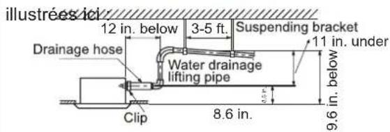
text_image
illustrées ici 12 in. below 3-5 ft. Suspending bracket Drainage hose Water drainage lifting pipe 11 in. under Clip 8.6 in. 9.6 in. belownatural_image
Close-up of a hand using a tool to adjust or install electronic components with visible wiring and connectors (no text or symbols)text_image
1 ft. Air outlet Air inlet Air outlet 5 ft. 8 ft. Over 5 ft. 5 ft.natural_image
Interior view of a ceiling-mounted industrial or mechanical assembly with visible structural components and mounting brackets (no text or symbols)natural_image
Close-up of hands installing or adjusting a wooden beam with a yellow tag, mounted on metal beams (no visible text or symbols)natural_image
Close-up of ceiling beams and fixtures with diagonal braces (no text or symbols visible)natural_image
Close-up of a mechanical assembly with intersecting metal frames and a central component (no visible text or symbols)natural_image
Close-up of hands using a tool to adjust or install a mechanical component (no visible text or symbols)natural_image
Close-up of hands using a mechanical clamp or tool to adjust a metal clamp (no text or symbols visible)
natural_image
Close-up of industrial machinery components with no visible text or symbolsnatural_image
Close-up of a white cylindrical object with a label, suspended in a dark container (no visible text or symbols)Étape 2 - Installation of the Indoor Unit (Cont.)
natural_image
Close-up of a hand holding an open air conditioner cover with visible wiring and components (no text or symbols)natural_image
Person installing or adjusting a white air conditioner unit with visible wiring and components (no text or symbols)
natural_image
Close-up of hands installing or adjusting a black plastic component with wires inside an appliance (no visible text or symbols)H. (suite)
natural_image
Two-panel image showing a hand inserting a fan into an air conditioner cover, and a close-up of the interior air vent (no text or symbols visible)natural_image
Close-up of a metallic pipe fitting mounted on a dark metal frame, with no visible text or symbols.natural_image
Close-up of a white cylindrical object mounted on a dark surface, with wooden beams and no visible text or symbols.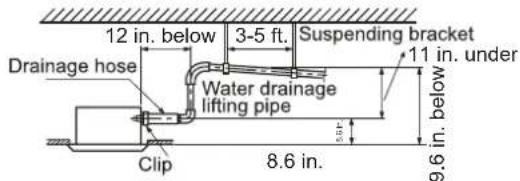
text_image
12 in. below 3-5 ft. Suspending bracket Drainage hose Water drainage lifting pipe Clip 8.6 in. 9.6 in. below 11 in. underCorriente Eléctrica
natural_image
Close-up of a hand using a tool to adjust or install electronic components with visible wiring and connectors (no text or symbols)text_image
1 ft. Air outlet Air inlet Air outlet 5 ft. 8 ft. Over 5 ft. 5 ft.Paso 1 – Préparation
natural_image
Interior view of a ceiling-mounted industrial or mechanical assembly with transparent structural beams and internal components (no visible text or symbols)natural_image
Close-up of hands installing a wooden beam on a metal frame (no visible text or symbols)natural_image
Interior ceiling view of a wooden structure with exposed beams and fixtures (no text or symbols visible)natural_image
Interior view of a ceiling-mounted industrial structure with visible structural beams and components (no text or symbols)natural_image
Close-up of hands using a tool to adjust or install electronic components on a black box (no visible text or symbols)natural_image
Close-up of hands using a mechanical clamp or tool to adjust a metal bracket (no visible text or symbols)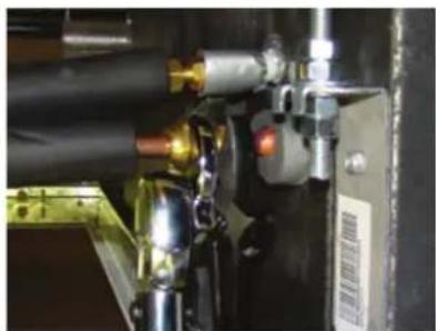
natural_image
Close-up of mechanical components with no visible text or symbolsnatural_image
Close-up of a white cylindrical object mounted on a dark surface, with wooden beams and yellow clamps visible (no text or symbols)Paso 2 - Installation of the Indoor Unit (Cont.)
natural_image
Close-up of a hand inserting electronic components into a white fan or computer chassis (no visible text or symbols)natural_image
Person installing or adjusting a white air conditioner unit with visible wiring and components (no text or symbols)
natural_image
Close-up of hands installing or adjusting cable components on a device (no visible text or symbols)H (cont.).