NV51T5511BSS - Oven SAMSUNG - Free user manual and instructions
Find the device manual for free NV51T5511BSS SAMSUNG in PDF.

User questions about NV51T5511BSS SAMSUNG
0 question about this device. Answer the ones you know or ask your own.
Ask a new question about this device
Download the instructions for your Oven in PDF format for free! Find your manual NV51T5511BSS - SAMSUNG and take your electronic device back in hand. On this page are published all the documents necessary for the use of your device. NV51T5511BSS by SAMSUNG.
USER MANUAL NV51T5511BSS SAMSUNG
Built-In Electric Wall Oven
Installation manual
NV51K7770** / NV51K6650** / NV51*5****

text_image
SAMSUNGinstall_NV10005_DG31-009625-03_EN.ind. 1 2019-11-11 国:13648
SAMSUNG
ContentsContents
Safety informations 2
Related equipment safety 2
Transport 2
Preparation 4
Checklist 4
Prepare to install the oven 4
Location requirements 5
Product dimensions - single ovens (NV51K7770S, NV51K6650S) 5
Product dimensions - single oven (NV51 ^5 S ^** S ^ ) 6
Cabinet dimensions - single ovens 6
Product dimensions - double ovens (NV51K7770D, NV51K6650D) 7
Product dimensions - double oven (NV51*5***D*) 8
Cabinet dimensions - double ovens 8
Installation instructions 10
Prepare built-in oven 10
Remove and replace oven door(s) 11
Electrical connection 13
Install oven 15
Self-diagnosis 16
Temp sensor & Heater check 16
Safety informations
Related equipment safety
Remove all tape and packaging before using the appliance. Dispose of the packaging after unpacking the appliance. Never allow children to play with packaging material.
Never modify or alter the construction of the appliance. For example, do not remove panels, wire covers or screws.
Transport
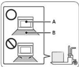
To avoid damage to the oven vent, use the transport method shown in the picture below.
text_image
A B NoA. Front
B. Pallet
Support the bottom of the oven from either side when moving it into the installation location. Leave the unit attached to the shipping pallet until it is in front of the cabinet opening and is ready to be lifted into place.
DANGER
ELECTRICAL SHOCK HAZARD
To avoid risk of electrical shock, personal injury or death; verify your appliance has been properly grounded in accordance with local codes or in absence of codes, with the National Electrical Code (NEC). ANSI/NFPA 70-latest edition.
WARNING
MOVING HAZARD
To avoid risk of severe personal injury; this appliance requires two or more people while handling and moving. Use of appliance moving devices is recommended.
2 English
WARNING
• The information in this manual should be followed exactly.
- A fire or electrical shock may result causing property damage, personal injury or death.
- Important Save this installation manual for local electrical inspector's use.
- Proper Installation - Be sure your appliance is properly installed and grounded by a qualified technician.
- New branch circuit installations (1996 NEC), mobile homes, recreational vehicles, or installations where local codes prohibit grounding through the neutral conductor require 4-wire branch-circuit connection.
- Improper connection of aluminum house wiring to copper leads can result in an electrical hazard or fire. Use only connectors designed for joining copper to aluminum and follow the manufacturer's recommended procedure closely.
- Mounting screws must be used.
- Failure to do so can result in the oven falling out of the cabinet causing serious injury.
CAUTION
- Make sure the cabinets and wall coverings around the oven can withstand the temperature (up to 194 °F [90 °C]) generated by the oven.
• Discoloration, delamination or melting may occur.
- DO NOT remove spacers on the side walls of the built-in oven.
- These spacers center the oven in the space provided. The oven must be centered to prevent excess heat buildup that may result in heat damage or fire.
A WARNING
• The information in this manual should be followed exactly.
- A fire or electrical shock may result causing property damage, personal injury or death.
IMPORTANT NOTE
Proper installation is the responsibility of the installer and product failure due to improper installation is NOT covered under warranty.
WARNING
- DO NOT put any weight on the oven door. Never allow anyone to climb, sit, stand or hang on the oven door.
- The oven could tip and injury might result from food or the oven itself.
WARNING
- The electrical power must be shut off while the electrical connections are being made.
- Failure to do so can result in severe personal injury, death or electrical shock.
IMPORTANT NOTE
- Observe all governing codes and ordinances. This appliance must be properly grounded.
- Keep oven vent ducts unobstructed. The oven vent is located bottom of the oven. This area could become hot during oven use. Never block this vent or place plastic or heat-sensitive items in front of it.
Preparation
Checklist
Use this checklist to verify that you have completed each step of the installation process. This can help you avoid mistakes.
- Before installing the oven, be sure to verify the cabinet dimensions are correct for your unit and the required electrical connections are present.
-
Refer to the installation manual for content regarding Safety, Cabinet Dimensions, Removing Packaging, Electrical Installation, Testing the Installation and Customer Service.
-
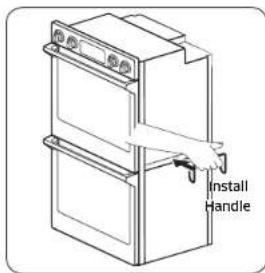
To lift up the oven, hang the install handle onto the side hook of the unit.
-
Move the oven unit into place in front of the cabinet opening, leaving the bottom packaging on the unit to avoid damaging flooring.
-
Team lift the unit directly into the cabinet cutout taking care not to pinch fingers or scratch hands or arms. Make sure the electrical conduit reaches to the connection point properly.
-
Slide the unit all the way into place, making sure to route the electrical conduit correctly.
-
Fasten the oven unit to the cabinetry opening with screws supplied (using Phillips screwdriver).
-
Consult the complete installation instructions and follow the remainder of the procedures listed, including performing an operation test.
-
All product literature and accessories are supplied (may be wrapped or boxed) with the oven.
-
INSTALLER - Leave the literature pack and the accessories with the customer.
-
Hang the install handle onto the side hook of the oven.
Prepare to install the oven
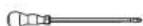
Phillips Screwdriver Drill
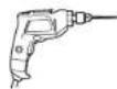
Prepare to install the oven

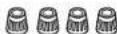
6 screws (M4 L16) 6 Wood Screws For Mounting (4 needed for installation and 2 extra's)
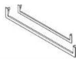
30" (76.2 cm) Metal Bottom Trim
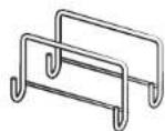
Install Handle (only for double oven)
Materials needed

Junction Box Wire Nuts

^3/_4 " Conduit Connector
4 English

Location requirements
IMPORTANT: Observe all governing codes and ordinances.
- Cabinet opening dimensions that are shown must be used. Given dimensions provide minimum clearance with oven.
- Recessed installation area must provide complete enclosure around the recessed portion of the oven.
- Grounded electrical supply is required. See "Electrical Requirements" section.
- Electrical supply junction box should be located 3" (7.6 cm) maximum below the support surface when the oven is installed in a wall cabinet. A 1" (2.5 cm) minimum diameter hole should have been drilled in the right rear or left rear corner of the support surface to pass the appliance cable through to the junction box.

NOTE
For under counter installation, it is recommended that the junction box be located in the adjacent right or left cabinet. If you are installing the junction box on rear wall behind oven, it is recommended that the junction box be recessed and located in the upper Right of the cabinet.
- Oven support surface must be solid, level and flush with bottom of cabinet cutout.
• Floor must be able to support a single oven weight of 199 lb (90 Kg)
• Floor must be able to support a double oven weight of 331 lb (150 Kg).
IMPORTANT: To avoid damage to your cabinets, check with your builder or cabinet supplier to make sure that the materials used will not discolor, delaminate or sustain other damage. This oven has been designed in accordance with the requirements of UL and CSA International and complies with the maximum allowable wood cabinet temperatures of 194°F (90°C).
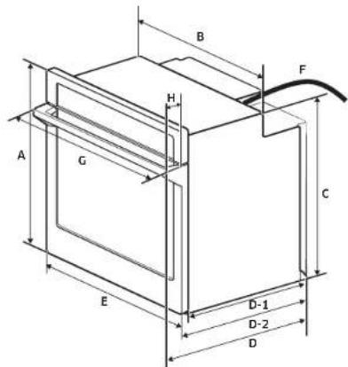
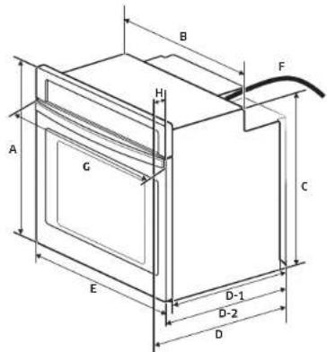
Product dimensions - single ovens (NV51K7770S, NV51K6650S)
text_image
B F H A G C E D-1 D-2 D| DIMENSION | ||
| A 28 | ^13/_16" (73.1 cm) Overall height | |
| B 28 | ^1/_2" (72.4 cm) Recessed width | |
| C 27 | ^2/_16" (69.1 cm) Recessed height | |
| D 26 | ^15/_16" (68.5 cm) Overall depth (with Handle) | |
| D-1 23 | ^1/_3" (58.7 cm) Recessed depth | |
| D-2 24 | ^2/_3" (62.0 cm) Overall depth | |
| E 29 | ^3/_4" (75.6 cm) Door width | |
| F | 47/4" (120 cm) | Conduit length |
| G | 30" (76.0 cm) | Overall width (Handle width) |
| H | 29/16" (6.5 cm) | Handle depth |
English 5
Preparation
Product dimensions - single oven (NV51*5***S*)
text_image
B H F A G C E D-1 D-2 D| DIMENSION | ||
| A 28 | ^13/_15 (73.1 cm) Overall height | |
| B 28 | ^1/_2 (72.4 cm) Recessed width | |
| C 27 | ^1/_15 (69.1 cm) Recessed height | |
| D 26 | ^1/_8 (67.6 cm) Overall depth (with Handle) | |
| D-1 23 | ^1/_8 (58.7 cm) Recessed depth | |
| D-2 24 | ^3/_8 (62.0 cm) Overall depth | |
| E 29 | ^3/_10 (75.6 cm) Overall width (Door width) | |
| F 47 | ^1/_20 (120 cm) Conduit length | |
| G | 28^5/_15 (72.5 cm) Handle width | |
| H | 2^-/_4 (5.7 cm) | Handle depth |
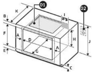
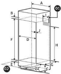
Cabinet dimensions - single ovens
Single Oven Under counter
01 Gas or Electric cooktops may be installed over this oven. See cooktop installation instructions for cutout size. See label on top of approved cooktop models.
02 Gas and Electrical Connections for Gas Cooktop Must be Located in an Adjacent Accessible Location to the Right.
text_image
01 B K I F A D G A H J C 02| DIMENSION | |
| A | Min. 1^1/2 ′′ (1.75 cm) - Overlap of Over Side Edges of Cutout |
| B | Min. 4^1/2 ′′ (10.5 cm) |
| C | 3^3/8 ′′ (9.1 cm) |
| D | Min. 28^1/2 ′′ / Max. 28^5/8 ′′ (Min. 72.4 cm / Max. 72.7 cm) |
| E | Min. 1 ′′ / Max. 1^-1/4 ′′ (Min. 2.5 cm / Max. 3.2 cm) |
| F | Min. 27^1/4 ′′ / Max. 27^4/8 ′′ (Min. 69.2 cm / Max. 69.5 cm) |
| G | Min. 23^1/2 ′′ (Min. 59.7 cm) |
| H | Min 22^ ′′ (Min 55.9 cm) |
| I | Max. 9^1/2 ′′ (Max. 24.1 cm) - Junction Box |
| J 36 | 1/8 ′′ (92.3 cm) - Counter top Height |
| K | 25′′ (63.5 cm) |
6 English
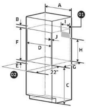
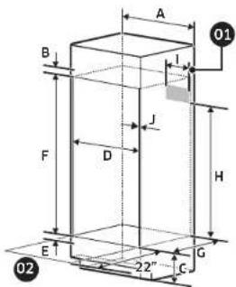
Single Oven Wall Mount
01 Junction Box
02 Allow a minimum of 22" for clearance to adjacent corners, drawers, walls, etc. when door is open
text_image
A B I J F D H E 22" G C 01 02| DIMENSION | |
| A 30" (76.2 cm) | |
| B Min. 1 | ^2/_4 " (3.5 cm) |
| C Min. 3 | 1" (Min. 78.7 cm) |
| D Min. 28 | ^1/_2 / Max. 28^2/_3 " (Min. 72.4 cm / Max. 72.7 cm) |
| E Min. 1" / Max. 1 | ^1/_4 " (Min. 2.5 cm / Max. 3.2 cm) |
| F Min. 27 | ^1/_4 / Max. 27^2/_3 " (Min. 69.2 / Max. 69.5 cm) |
| G Min. 23 | ^1/_2 " (Min. 59.7 cm) |
| H Min. 2 | 2" (Min. 55.9 cm) |
| I Max. 9 | ^1/_2 " (Max. 24.1 cm) - Junction Box |
| J Min. | ^11/_15 " (1.75 cm) - Wooden cabinet thickness |
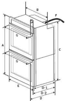
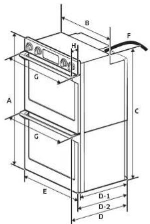
Product dimensions - double ovens (NV51K7770D, NV51K6650D)

text_image
B H F G A C G E D-1 D-2 D| DIMENSION | ||
| A 51 | ^1/_2 (130.7 cm) Overall height | |
| B 28 | ^-/_2 (72.4 cm) Recessed width | |
| C | 49°/s" (126.7 cm) | Recessed height |
| D | 26 ^15 / _16 (68.5 cm) | Overall depth (with Handlc) |
| D-1 | 23°/4" (58.7 cm) Recessed depth | |
| D-2 | 24°/s" (62.0 cm) | Overall depth |
| E | 29°/4" (75.6 cm) | Door width |
| F | 67" (170 cm) | Conduit length |
| G | 30" (76.0 cm) | Overall width (Handle width) |
| H | Z ^2 / _18 (6.5 cm) | Handle depth |
English 7
Preparation
Product dimensions - double oven (NV51*5***D*)
text_image
B H F G A C G E D-1 D-2 D| DIMENSION | ||
| A 51 | ^1/_2 " (130.7 cm) Overall height | |
| B | 28^1/_2 " (72.4 cm) Recessed width | |
| C | 49^7/_6 " (126.7 cm) | Recessed height |
| D | 26^5/_8 " (67.6 cm) | Overall depth (with Handle) |
| D-1 | 23^1/_4 " (58.7 cm) Recessed depth | |
| D-2 | 24^3/_4 " (62.0 cm) | Overall depth |
| E | 29^3/_4 " (75.6 cm) | Overall width (Door width) |
| F | 67 " (170 cm) | Conduit length |
| G | 28^5/_16 " (72.5 cm) | Handle width |
| H | 2^1/_2 " (5.7 cm) | Handle depth |
text_image
A B I J F D H E 22" C G 01 02| DIMENSION | |
| A 30" (76.2 cm) | |
| B Min. 1 | ^3/_16" (3.0 cm) |
| C 12" (30.5 cm) | |
| D Min. 28 | ^1/_2" / Max. 28 ^2/_6" (Min. 72.4 cm / Max. 72.7 cm) |
| E Min. 1" / Max. 1 | ^1/_4" (Min. 2.5 cm / Max. 3.2 cm) |
| F 50 | ^1/_7" (127.6 cm) |
| G Min. 23 | ^1/_7" (Min. 59.7 cm) |
| H Min 47" (Min. 119.4 cm) | |
| I Max. 9 | ^1/_7" (Max. 24.1 cm) - Junction Box |
| J Min. | ^11/_15" (1.75 cm) - Wooden cabinet thickness |
8 English
If codes permit and a separate ground wire is used, it is recommended that a qualified electrical installer determine that the ground path and the wire gauge are in accordance with local codes.
Check with a qualified electrical installer if you are not sure the oven is properly grounded.
This oven must be connected to a grounded-metal permanent wiring system.
Be sure that the electrical connection and wire size are adequate and in
conformance with the National Electrical Code, ANSI/NFPA 70-latest edition or CSA Standards C22.
1-94, Canadian Electrical Code, Part 1 and C22.2 No. O-M91-latest edition, and all local codes and ordinances.
A copy of the above code standards can be obtained from:
National Fire Protection Association
1 Batterymarch Park
Quincy, MA 02169-7471
CSA International
8501 East Pleasant Valley Road
Cleveland, OH 44131-5575
Electrical Connection
To properly install your oven, you must determine the type of electrical connection you will be using and follow the instructions provided in this manual.
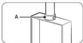
- Oven must be connected to the proper electrical voltage and frequency as specified on the model/serial/rating plate. The model/serial/rating plate is located on the bottom left side of the trim. See the following illustrations.
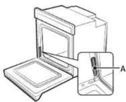
natural_image
Technical line drawing of a mechanical device with an inset view labeled A (no text or symbols present)Single Oven
A. Model/serial/rating plate
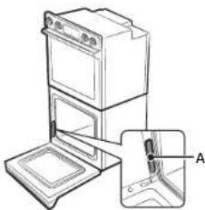
natural_image
Technical line drawing of a mechanical device with an inset view showing a component labeled A (no text or symbols present)Double Oven
A. Model/serial/rating plate
• A circuit breaker is recommended.
- Use the chart below to determine the minimum recommended dedicated circuit protection.
| KW Rating (240 V) KW | Rating (208 V) | Recommended Circuit Size (Dedicated) |
| ≤4.8 KW ≤4.1 KW | 20 Amp | |
| 4.9 KW - 7.5 KW 4.3 | KW - 6.2 KW 30 Amp | |
| 7.3 KW - 9.6 KW 6.3 | KW - 8.3 KW 40 Amp | |
| 9.7 KW - 12.0 KW 8.4 | KW - 10.4 KW 50 Amp |
- Connect directly to the circuit breaker box (or fused disconnect) through flexible, armored or nonmetallic sheathed, copper cable (with grounding wire). See "Electrical Connection" section.
Installation instructions
- Flexible conduit from the oven should be connected directly to the junction box.
- Fuse both sides of the line.
- Do not cut the conduit. The length of conduit provided is for serviceability of the oven.
• A UL listed or CSA approved conduit connector must be provided. - If the house has aluminum wiring, follow the procedure below:
- Connect a section of solid copper wire to the ends of the flexible conduit leads.
- Connect the aluminum wiring to the added section of copper wire using special connectors and/or tools designed and UL listed for joining copper to aluminum.
Follow the electrical connector manufacturer's recommended procedure. Aluminum/copper connection must conform with local codes and industry accepted wiring practices.
For power requirements for models NV51K6650D, NV51K6650S, NV51K7770D, NV51K7770S, NV51 ^5 ^'' D, and NV51 ^5 ^'' S, refer to the following table.
| Model | 240 VAC 208 VAC | |
| kW kW | ||
| NV51K6650D 9.3 7 | 0 | |
| NV51K6650S 4.9 3 | 7 | |
| NV51K7770D 10.6 | 8.0 | |
| NV51K7770S 6.2 4 | 7 | |
| NV51*5***D 8.9 6.7 | ||
| NV51*5***S 4.9 3.7 |
Installation instructions
Prepare built-in oven
A WARNING
Excessive Weight Hazard
Use two or more people to move and install an oven. Failure to do so can result in back or other injury.
- Decide on the final location for the oven. Avoid drilling or cutting into house wiring during installation.
- To avoid floor damage, set the oven on a cardboard prior to installation. Do not use handle or any portion of the front frame for lifting.
- Remove the shipping materials and tape from the oven. Remember to keep the packing materials that may be needed for installation.
- Remove the hardware package from inside of the bag containing literature.
- Remove racks and other parts from inside the oven.
- Move oven and cardboard close to the oven's final location.
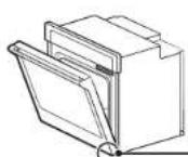
Remove and replace oven door(s)
IMPORTANT: Use two hands to remove oven door. For double ovens, repeat the process for each door. Prior to removing the oven door, prepare a surface where you will place it. This surface should be flat and covered with a soft blanket, or use the corner posts from your packaging material.
Disconnect LED light wire harness (Only NV51K7770\*\* / NV51K6650\*\*)
Locate the LED light wire harness and disconnect it before removing the door.
-Wire Harness
Single Oven Double Oven
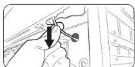
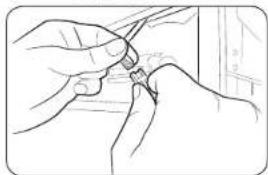
- Carefully pull the wire to reveal the connector.
natural_image
Line drawing of hands holding a small object near a window (no text or symbols)- Disconnect the connector.
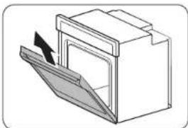
Remove oven door(s)
text_image
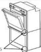
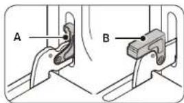
A BA. Oven door hinge lock in locked position
B. Oven door hinge lock in unlocked position
natural_image
Diagram of a door with an open lid and arrow indicating direction (no text or symbols)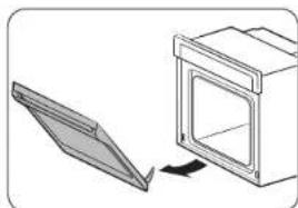
natural_image
Diagram showing a mechanical component being cut off into a housing (no text or symbols present)- Open the oven door.
-
Locate the oven door hinge locks in both corners of the oven door, and then rotate the hinge locks toward the oven door to the unlocked position (see illustration B). If the door hinge lock is not rotated fully, the door will not remove properly.
-
Partially close the door to engage the door latch locks. The door will stop at this point.
-
Partially close the door to engage the door latch locks. The door will stop at this point.
-
Using two hands, grasp the edges of the oven door. Lift and pull the oven door toward you and remove. You may need to gently shift door from side to side as you pull.
- Set the oven door(s) aside on the prepared covered work surface with the oven door resting on its handle.
- To continue with the oven installation, go to the "Positioning Oven Feet for Multiple Cabinet Cutout Heights" section.
Installation instructions
Replace oven door(s)
CAUTION
The door is very heavy. You may need help lifting the door high enough to slide it into the hinge slots. Do not lift the door by the handle.
natural_image
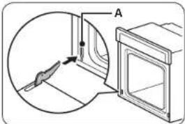
Diagram showing a door mechanism with an arrow and labeled section A, no text or symbols presentA. Slot in the oven cavity for door hinge lock
- Using two hands, grasp side edges of door at the midpoint. Face the oven cavity.
- Locate the slots on each side of the oven cavity for the door hinge locks.
natural_image
Diagram of a door opening with an arrow indicating direction (no text or symbols)- At a 45° angle, align door hinges with slots in the lower front of the oven cavity. Slowly insert door, making sure you maintain the 45° angle. You will know the door is engaged in the slot when you feel a slight drop.
natural_image
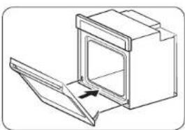
Simple line drawing of a door with an arrow indicating direction (no text or symbols)- Lower the oven door to the fully open position. If the oven door does not open to a full 90°, repeat steps 1 through 3.
- Locate the oven door hinge locks in the corners of the oven door, and rotate the hinge locks toward the oven cavity to the locked position.
See Step 1 (Illustration A) in the "Remove Oven Door(s)" section for proper locked position.
- Close the oven door
- When the hinges are properly installed and the door closed, there should be an even gap between the door and the control panel. If one side of the oven door is hanging lower than the other, the hinge on that side is not properly installed.
- Connect Wire Harness.
Electrical connection
For Double Ovens
WARNING
Electrical Shock Hazard
Disconnect power before servicing.
Use 8 gauge solid copper wire.
Make sure to ground the oven.
Failure to follow these instructions can result in death, fire, or electrical shock.
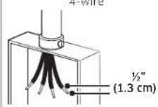
This oven is manufactured with a neutral (white) power supply wire and a cabinet-connected ground (green or bare) wire twisted together.
A. UL listed or CSA approved conduit connector
- Disconnect power.
- Feed the flexible conduit from the oven through the opening in the cabinet.
- Remove junction box cover if it is present.
- Install a UL listed or CSA approved conduit connector to the junction box.
- Route the flexible conduit from the oven to the junction box through a UL listed or CSA approved conduit connector.
- Tighten screws on conduit connector.
- See "Electrical Connection Options Chart" to complete installation for your type of electrical connection.
For Single Ovens
WARNING
Electrical Shock Hazard
Disconnect power before servicing.
Use 8 gauge solid copper wire.
Electrically ground oven
Failure to follow these instructions can result in death, fire, or electrical shock.
Electrical Connection Options Chart
| If your home has: Go to section: | |
 | 4-Wire Cable from Home Power Supply |
 | 3-Wire Cable from Home Power Supply |
NOTE
If the power connection is plugged in improperly, "bAd LinE" appears on the display. Reconnect the power connection properly, and the message disappears.
Installation instructions
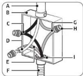
4-Wire Cable from Home Power Supply
IMPORTANT: Use the 4-wire cable from home power supply in the U.S. where local codes do not allow grounding through neutral, New Branch circuit installations (1996 NEC), mobile homes and recreational vehicles, new construction and in Canada.
text_image
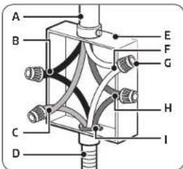
A B C D E F G H IA. Cable from home power supply
B. Black wires (normally L1)
C. Red wires (normally L2)
D. 4-wire flexible conduit from oven
E. Junction box
F. White wires (normally N-neutral)
G. UL listed wire connectors
H. green wires (normally G-ground)
I. UL listed or CSA approved conduit connector
- Connect the 2 black wires (B) together using a UL listed wire connector.
- Connect the 2 red wires (C) together using a UL listed wire connector.
- Untwist white wire from green (or bare) ground wire coming from the oven.
- Connect the 2 white wires (F) together using a UL listed wire connector.
- Connect the green (or bare) ground wire (H) from the oven cable to the green (or bare) ground wire (in the junction box) using a UL listed wire connector.
- Install junction box cover.
3-Wire Cable from Home Power Supply - U.S. Only
IMPORTANT: Use the 3-wire cable from home power supply where local codes permit a 3-wire connection.
text_image
A B C D E F G H IA. Cable from home power supply
B. Junction box
C. Black wires (normally L1)
D. White wires (normally N-neutral)
E. green wires (normally G-ground)
F. 4-wire flexible conduit from oven
G. Red wires (normally L2)
H. UL listed wire connectors
I. UL listed or CSA approved conduit connector
- Connect the 2 black wires (C) together using a UL listed wire connector.
- Connect the 2 white wires (D) and the green (or bare) ground wire (of the oven cable) using a UL listed wire connector.
- Connect the 2 red wires (C) together using a UL listed wire connector.
- Install junction box cover.
Install oven
text_image
Install Handle- Using 2 or more people, lift the oven partially into the cabinet cutout. Hang the install handle onto the side hook of the oven as shown below.
NOTE
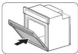
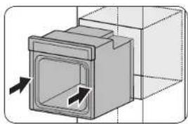
Carefully push against front oven frame.
natural_image
3D diagram of a mechanical component with directional arrows indicating movement or force (no text or symbols)- Push against the seal area of the front frame to push the oven into the cabinet until the back surface of the front frame touches the front wall of the cabinet.
natural_image
Diagram of a door with a magnified inset showing internal components (no text or symbols)-
Push oven completely into the cabinet and center the oven into the cabinet cutout.
-
Remove the tape from front trims.
-
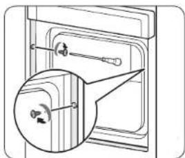
Securely fasten the oven to the cabinet using the screws provided.
- Insert the screws through hole in trim aligning with hole in oven frame. Do not overtighten screws.
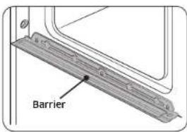
text_image
BarrierWARNING
When inserting the oven, use caution not to deform or damage the barrier underneath.
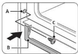
text_image
A B CA. Trim Left
B. Trim Bottom
C. Screw
- The bottom metal trim are shipped in the foam packing.
To install the metal bottom trim, see following instructions.
- Align tab of the bottom trim with a hole in the left side trim of the unit as shown. Repeat on the right side.
- Using one screw on each side of the trim tab, fasten the trim securely to the oven.
NOTE
The bottom trim piece is to cover any unwanted gaps.
6. If the cutout size is larger than 34 inches use of the wider bottom trim is recommended.
NOTE
To select the bottom trim properly, measure the cutout between cabinet and oven. See the following chart.
| TYPE | ||
| Cutout 0 - | ^3/_4" | ^3/_4" - 2^3/_4" |
Self-diagnosis
Temp sensor & Heater check
- After connecting the power, check if the display works properly.
- Remove all accessories (Gliding Rack, Flat-Rack, Smart Divider...etc.) from inside of the oven cavity.
- You cannot proceed with self-diagnosis if the oven cavity is hot or the door is open.
- In this case, "Hot or door" message appears on the display.
- To start self-diagnosis, press both Hidden Keys simultaneously for 5 seconds.
• Refer to the table below for the hidden keys for each model.
| Model NV51K6650** NV51K7770** | ||
| Control panel | ||
| Hidden Key | Keep Warm + "9" | UPPER + LOWERand touch 'Install test' ondisplay. |
| Model NV51*5**** | |
| Control panel | |
| Hidden Key | Keep Warm + "9" |
- If there is no error, 'PASS' appears on the display with an alert sound.
- If there is an error, following message appears on the display with an alert sound.
| Model | All models | ||
| Error code Remark | |||
| Feature | Upper Broil H | 2 | Double/Single Oven |
| Upper Bake H | 1 | ||
| Lower Broil H | 4 | Double Oven Only | |
| Lower Bake H | 3 | ||
- If an error occurs, contact a Samsung service center for further service.
NOTE
If you see any other error messages that are not listed above, please contact a Samsung service center. call e.g. 1-800-SAMSUNG (726-7864)
16 English

Memo


Memo


Memo


SAMSUNG

Scan the QR code* or visit
www.samsung.com/spsn
to view our helpful
How-to Videos and Live Shows
Requires water to be introduced on your smartphones
Please be advised that the Samsung warranty does NOT cover service calls to explain product operation, correct improper installation, or perform normal cleaning or maintenance.
QUESTIONS OR COMMENTS?
| COUNTRY CALL OR VISIT US ONLINE AT | ||
| U.S.AConsumer Electronics | 1-800-SAMSUNG (726-7864) www.samsung.com/us/support | |
| CANADA 1 800-SAMSUNG (726-7864) | www.samsung.com/ca/support (English)www.samsung.com/ca_fr/support (French) | |

DC68-00862A-09
text_image
B F H A G C E D-1 D-2 D| DIMENSIONES | ||
| A 28 | ^1/_w (73.1 cm) Altura total | |
| B 28 | ^1/_2 (72.4 cm) Ancho empotrado | |
| C 27 | ^2/_s (69.1 cm) Altura empotrada | |
| D 26 | ^1/_w (68.5 cm) Profundidad total (con manija) | |
| D-1 23 | ^1/_s (58.7 cm) Profundidad empotrada | |
| D-2 24 | ^2/_s (62.0 cm) Profundidad total | |
| E 29 | ^3/_s (75.6 cm) Ancho de la puerta | |
| F | 47^1/_s (120 cm) | Longitud del conducto |
| G | 30' (76.0 cm) | Ancho total (ancho manija) |
| H | 2^6/_s (6.5 cm) Profuncidad manija | |
Español 5

Preparación
text_image
B H F A G C E D-1 D-2 D| DIMENSIONES | ||
| A 28 | ^3/_16" (73.1 cm) Altura total | |
| B 28 | ^1/_2" (72.4 cm) Ancho empotrado | |
| C 27 | ^3/_16" (69.1 cm) Altura empotrada | |
| D 26 | ^5/_2" (67.6 cm) Profundidad total (con manija) | |
| D-1 23 | ^1/_2" (58.7 cm) | Profundidad empotrada |
| D-2 24 | ^3/_8" (62.0 cm) | Profundidad total |
| E 29 | ^3/_14" (75.6 cm) Ancho total (Ancho de la puerta) | |
| F 47 | ^1/_4" (120 cm) Longitud del conducto | |
| G 28 | ^5/_16" (72.5 cm) | Ancho manija |
| H | 2^1/_4" (5.7 cm) | Profundidad manija |
Dimensiones del gabinete: hornos simples
text_image
01 B K I F A D C A H J 02 E c| DIMENSIONES | |
| A | Min. 1^1/s^2 (1.75 cm) - Superosición ce los bordes laterales de la abertura recortada |
| B | Min. 4^1/s^2 (10.5 cm) |
| C | 3^1/s^2 (9.1 cm) |
| D | Min. 28^1/s^2 / Máx. 26^2/s^2 (Mín. 72.4 cm / Máx. 72.7 cm) |
| E | Min. 1^* / Máx. 1^1/s^2 (Mín. 2.5 cm / Máx. 3.2 cm) |
| F | Min. 27^1/4^* / Máx. 27^1/s^2 (Mín. 69.2 cm / Máx. 69.5 cm) |
| G | Min. 23^1/s^2 (Mín. 59.7 cm) |
| H | Mín 22" (Mín 55.9 cm) |
| I | Máx. 9^1/s^2 (Máx. 24.1 cm) - Caja de empalmes |
| J | 36^1/s^2 (92.3 cm) - Altura de la mesada |
| K | 25" (63.5 cm) |
6 Español
text_image
A B I 01 F J D H E G 22" C 02| DIMENSIONES | |
| A 50" (76.2 cm) | |
| B Min. 1 | 34 " (3.5 cm) |
| C Min. 31" (Min. 78.7 cm) | |
| D Min. 29 | 12 " / Máx. 28 58 " (Min. 72.4 cm / Máx. 72.7 cm) |
| E Min. 1" / Máx. 1 | 14 " (Min. 2.5 cm / Máx. 3.2 cm) |
| F Min. 27 | 14 " / Máx. 27 78 " (Min. 69.2 / Máx. 69.5 cm) |
| G Min. 23 | 15 " (Min. 59.7 cm) |
| H Min. 22" (Min. 55.9 cm) | |
| I Máx. 9 | 15 " (Máx. 24.1 cm) - Caja de empalmes |
| J Min | 12/s " (1.75 cm) - Grosor del gabinete de madera |
text_image
B H F G A C G E D-1 D-2 D| DIMENSIONES | ||
| A 51 | 12 ° (130.7 cm) Altura total | |
| B 28 | -12 ° (72.4 cm) | Ancho empotrado |
| C | 49^/s ° (126.7 cm) | Altura empotrada |
| D | 26^/s ° (68.5 cm) | Profundidad total (con manija) |
| D-1 | 23^/s ° (58.7 cm) | Profundidad empotrada |
| D-2 | 24^/s ° (62.0 cm) | Profundidad total |
| E | 29^/s ° (75.6 cm) | Ancho de la puerta |
| F | 67^ (170 cm) | Longitud del conducto |
| G | 30^ (76.0 cm) | Ancho total (ancho manija) |
| H | 2^/s ° (6.5 cm) | Profundidad manija |
Español 7
Preparación
text_image
B F G A C G E D-1 D-2 D| DIMENSIONES | ||
| A 51 | 12" (130.7 cm) Altura total | |
| B | 28^1/_2" (72.4 cm) | Ancho empotrado |
| C | 49^7/_6" (126.7 cm) | Altura empotrada |
| D | 26^5/_8" (67.6 cm) | Profundidad total (con manija) |
| D-1 | 23^1/_8" (58.7 cm) | Profundidad empotrada |
| D-2 | 24^3/_8" (62.0 cm) | Profundidad total |
| E | 29^3/_4" (75.6 cm) | Ancho total (Ancho de la puerta) |
| F | 67" (170 cm) | Longitud del conducto |
| G | 28^9/_16" (72.5 cm) | Ancho manija |
| H | 2^1/_4" (5.7 cm) | Profundidad manija |
text_image
A B I J F D H E 22" c G 01 02| DIMENSIONES | |
| A 30" (76.2 cm) | |
| B Min. 1 | 12 / 14 " (3.0 cm) |
| C 12" (30.5 cm) | |
| D Mín. 28 | 12 " / Máx. 28 ^2 / ^3 " (Mín. 72.4 cm / Máx. 72.7 cm) |
| E Mín. 1" / Máx. 1 | 14 " (Mín. 2.5 cm / Máx. 3.2 cm) |
| F 50 | 14 " (127.6 cm) |
| G Mín. 23 | 15 " (Mín. 59.7 cm) |
| H Mín. 47" (Mín. 119.4 cm) | |
| I Máx. 9 | 15 " (Máx. 24.1 cm) - Caja de empalmes |
| J Mín. | 11/' (1.75 cm) - Grosor del gabinete de madera |
8 Español
National Fire Protection Association
1 Batterymarch Park
Quincy, MA 02169-7471
CSA International
8501 East Pleasant Valley Road
Cleveland, OH 44131-5575
Conexión eléctrica
natural_image
Technical line drawing of a mechanical device with an inset view labeled A (no text or symbols present)Horno simple
natural_image
Technical line drawing of a mechanical device with an inset showing a close-up view of a component (no text or symbols present)Horno doble
natural_image
Line drawing of two hands holding a small object, no text or symbols present- Desconéctelo.
natural_image
Diagram of a door with an open lid and a directional arrow indicating force or movement (no text or symbols)
natural_image
Diagram showing a mechanical component being cut with an arrow indicating rotation (no text or symbols present)natural_image
Diagram showing a door opening with a tool inside, no text or symbols presentnatural_image
Diagram of a door opening with an arrow indicating direction (no text or symbols)natural_image
Simple line drawing of a door with an arrow indicating direction (no text or symbols)text_image
A B C D E F G H Itext_image
A B C D E F G H Inatural_image
3D diagram of a mechanical component with directional arrows indicating movement or force (no text or symbols)natural_image
Diagram of a door with a screwdriver inserted, showing internal components and a magnified view of the door (no text or symbols present)
Scan this with your smartphone
text_image
B F H A G C E D-1 D-2 Dtext_image
B H F A G C E D-1 D-2 Dtext_image
01 B K I F A D G E A H J C 02| DIMENSIONS | |
| A | Mini 112 /s" (1,75 cm) - Chevauchement des bords latéraux de découpe |
| B | Minimum 412 /s" (10,5 cm) |
| C | 3^12 /s" (9,1 cm) |
| D | Minimum 2812 /s" / Maximum 28^12 /s" (Minimum 72,4 cm / Maximum 72,7 cm) |
| E | Minimum 1 /s" / Maximum 112 /s" (Minimum 2,5 cm / Maximum 3,2 cm) |
| F | Minimum 2712 /s" / Maximum 2712 /s" (Minimum 69,2 / Maximum 69,5 cm) |
| G | Minimum 23^12 /s" (Minimum 59,7 cm) |
| H | Minimum 22 /s" (Minimum 55,9 cm) |
| I | Maximum 912 /s" (Maximum 24,1 cm) - Boîte de jonction |
| J | 3612 /s" (92,3 cm) - Hauteur du plan de travail |
| K | 25 /s" (63,5 cm) |
6 Français
text_image
A B I 01 F J D H E 22" G C 02| DIMENSIONS | |
| A 50" (76,2 cm) | |
| B Minimum 1 | 18 " (3,5 cm) |
| C Minimum 31" (Minimum 78,7 cm) | |
| D | Minimum 2812" / Maximum 2812" (Minimum 72.4 cm / Maximum 72.7 cm) |
| E Minimum 1" / Maximum 1 | 14" (Minimum 2,5 cm / Maximum 3,2 cm) |
| F Minimum 27 | 14" / Maximum 2718" (Minimum 69,2 / Maximum 69,5 cm) |
| G Minimum 23 | 15" (Minimum 59,7 cm) |
| H Minimum 22" (Minimum 55,9 cm) | |
| I Maximum 9 | 12" (Maximum 24,1 cm) - Boîte de jonction |
| J Minimum | 118 " (1,75 cm) - Épaisseur du meuble en bois |
Dimensions de l'appareil (fours doubles - NV51K7770D, NV51K6650D)
text_image
B H F G A C G E D-1 D-2 Dtext_image
B H F G A C G E D-1 D-2 DNational Fire Protection Association
1 Batterymarch Park
Quincy, MA 02169-7471
CSA International
8501 East Pleasant Valley Road
Cleveland, OH 44131-5575
natural_image
Technical line drawing of a mechanical device with an inset view showing a component labeled A (no text or symbols present)Four simple
natural_image
Technical line drawing of a mechanical device with a close-up view of its internal structure (no text or symbols)Four double
natural_image
Line drawing of two hands holding a small object near a window (no text or symbols)natural_image
Diagram of a door with an open lid and arrow indicating direction (no text or symbols)
natural_image
Diagram showing a mechanical component being cut with an arrow indicating rotation (no text or symbols present)text_image
Diagram showing a device with labeled components and directional arrows, likely illustrating a mechanical or electrical assembly.natural_image
Diagram of a mechanical device with an open lid and arrow indicating direction (no text or symbols)natural_image
Simple line drawing of a door with an arrow indicating direction (no text or symbols)text_image
A B C D E F G H Itext_image
A B C D E F G H Inatural_image
3D diagram of a mechanical component with arrows indicating direction, no text or symbols presentnatural_image
Diagram of a door handle mechanism with a magnified inset showing internal components (no text or labels)
Scan this with your smartphone