STAR_PS_03 - Projection screen Fromm & Starck - Free user manual and instructions
Find the device manual for free STAR_PS_03 Fromm & Starck in PDF.

| Product type | Manual projection screen |
| Brand | Fromm & Starck |
| Model | STAR_PS_03 |
| Screen dimensions (W x H) | 2214 x 1245 mm |
| Image format | 16:9 |
| Weight | 5.21 kg |
| Screen material | Matte white projection fabric |
| Installation type | Wall or ceiling mount |
| Deployment mechanism | Manual (pull cord) |
| Power supply | None (manual) |
| Main functions | Image projection, retractable, portable |
| Included items | Screen, mounting kit (rings, cords, elastic bands, wall plugs) |
| Maintenance and cleaning | Clean with a soft, dry cloth. Do not use chemical products. |
| Safety | Do not fold the screen, do not write on it, keep out of reach of children, do not use outdoors in bad weather. |
| Spare parts and repairability | Contact the manufacturer for any defective parts. No user repair. |
| General information | Indoor use only. Assembly recommended by two people. |
Frequently Asked Questions - STAR_PS_03 Fromm & Starck
User questions about STAR_PS_03 Fromm & Starck
0 question about this device. Answer the ones you know or ask your own.
Ask a new question about this device
Download the instructions for your Projection screen in PDF format for free! Find your manual STAR_PS_03 - Fromm & Starck and take your electronic device back in hand. On this page are published all the documents necessary for the use of your device. STAR_PS_03 by Fromm & Starck.
USER MANUAL STAR_PS_03 Fromm & Starck
1


natural_image
Technical line drawing of a structural frame with multiple circular insets showing different component views (no text or symbols)
This User Manual has been translated for your convenience using machine translation. Reasonable efforts have been made to provide an accurate translation; however, no automated translation is perfect nor is it intended to replace human translators. The official User Manual is the English version. Any discrepancies or differences created in the translation are not binding and have no legal effect for compliance or enforcement purposes. If any questions arise related to the accuracy of the information contained in the User Manual, please refer to the English version of those contents which is the official version.
Technical data
| Parameter description | Parameter value |
| Product name | Projector screen |
| Model | STAR_PS_03 |
| Screen dimensions [mm] | 2214x1245 |
| Weight [kg] | 5.21 |
General Description
This manual is intended to assist you for safe and reliable use. The product is designed and manufactured strictly according to technical specifications using the latest technology and components, and maintaining the highest quality standards.
CAREFULLY READ AND UNDERSTAND THIS MANUAL BEFORE USE.
To ensure long and reliable operation of the product, operate and maintain it correctly, strictly in compliance with this manual. The technical data and specifications in this manual are up-to-date. The manufacturer reserves the right to modifications for the purpose of quality improvement.
Explanation of symbols
 | Read the manual before use. |
 | CAUTION! or WARNING! or REMEMBER!General warning sign. |

CAUTION! The figures in this manual are illustrative only and may vary in some details from the actual appearance of the product.
SAFETY OF USE
The term "device" or "product" in the warnings and in the description of the manual refers to
Projector screen
a) If in doubt as to whether the product is working properly or found to be damaged, contact the manufacturer's technical service.
b) Keep this manual for future reference. If the product is to be handed over to a third party, hand it over with this user manual.
c) Keep packaging components and small installation parts out of the reach of children.
d) Keep the product away from children and animals.
e) When using this product with other devices, also follow the other instructions for use.
f) The product is not a toy. Children should not play with the product.
g) Keep the product away from sources of fire and heat.
h) Do not touch the screen surface.
i) Do not write or draw on the surface of the screen.
j) Do not fold the screen!
k) Do not use the product outdoors in bad weather, especially in rain and wind.
I) When using the product outside, do not leave it overnight, regardless of the weather.

CAUTION!
Although the device is designed to be safe, it is recommended to exercise caution and common sense when using it.
ASSEMBLY OF THE UNIT
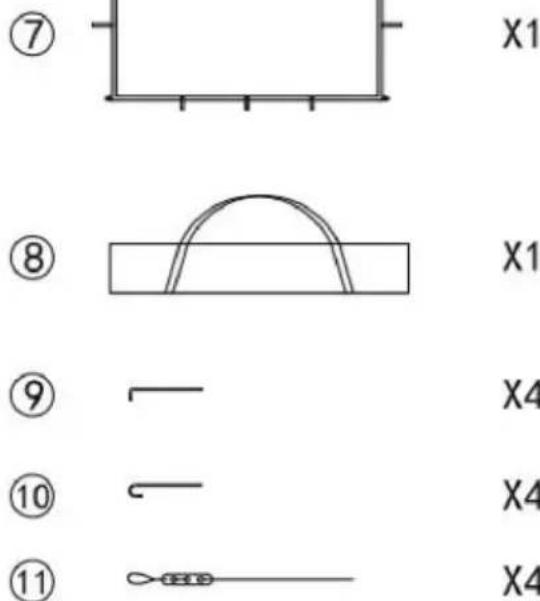
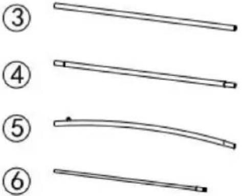
Assembly elements
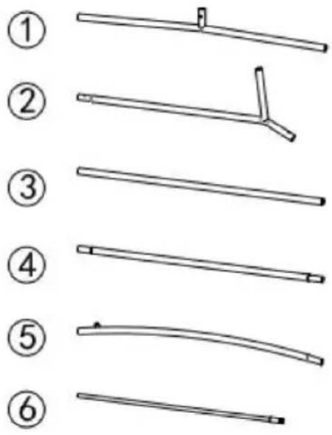
X2
X2
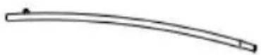
natural_image
Simple line drawing of a bent rod or support structure with no text or symbolsX1
X2

X2

X2

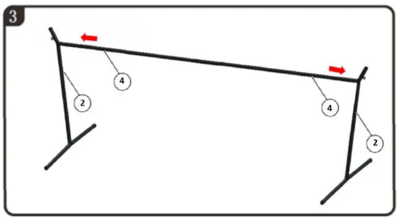
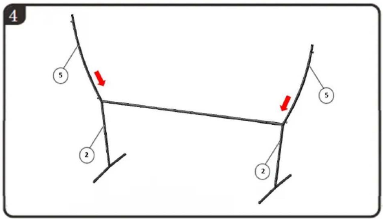
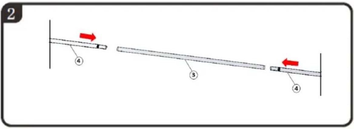
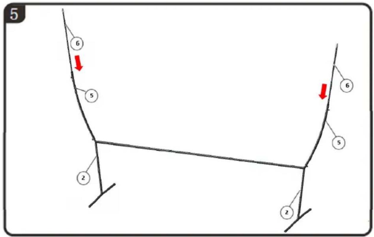
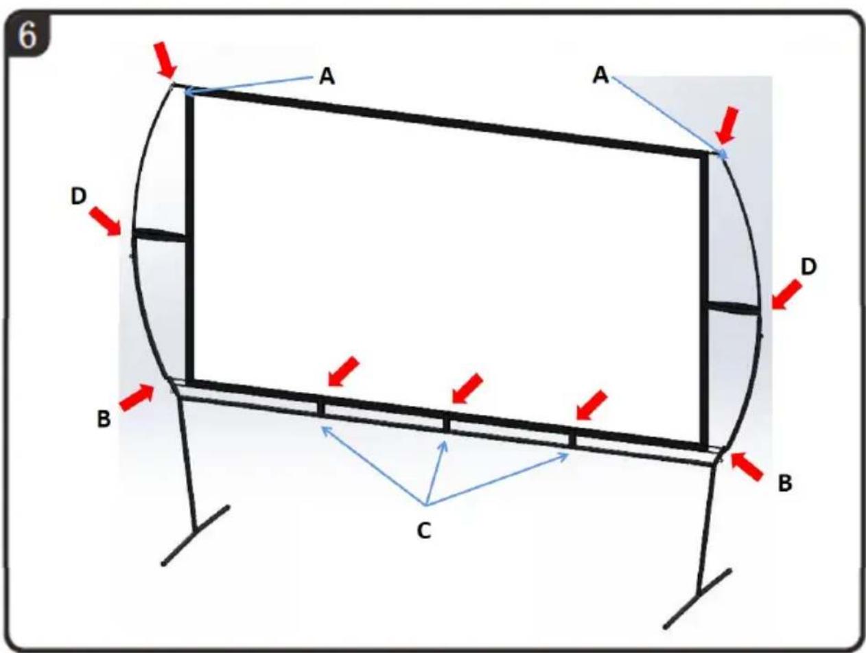
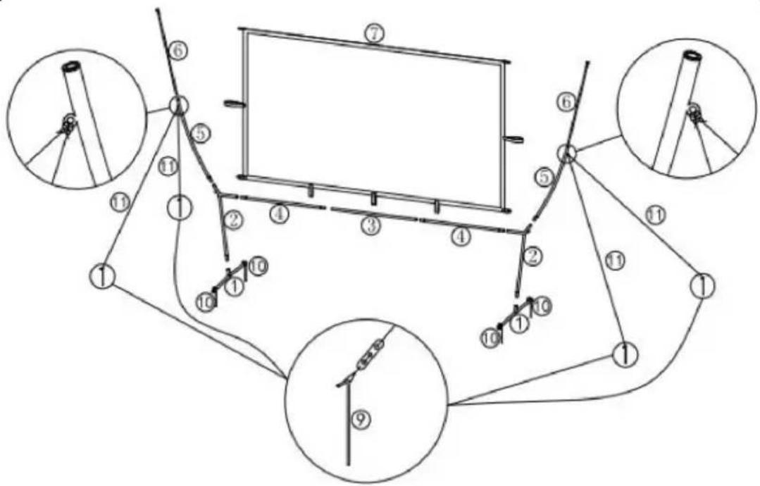
ASSEMBLY
CAUTION! It is recommended that at least two people assembly it.

1


A. Place the rings in the metal tunnels
B. Hang a plastic rope
C. Install the elastic band
D. Install the elastic band
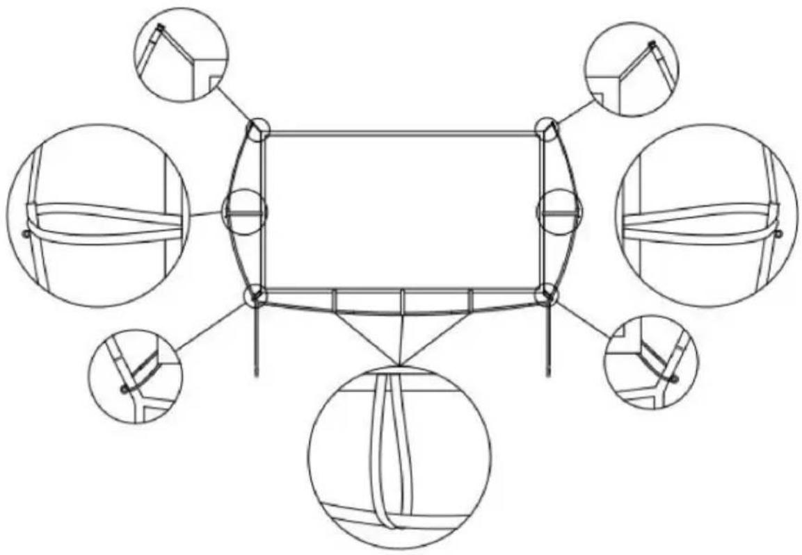
natural_image
Technical line drawing of a structural frame with multiple circular insets showing different component views (no text or symbols)
natural_image
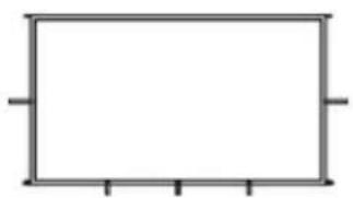
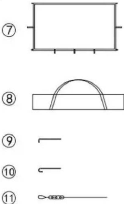
Simple rectangular frame with corner markers (no text or symbols)X1
⑧
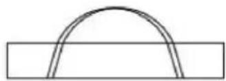
X1
⑨

X4
⑩

X4
⑪

X4
MONTAŻ
natural_image
Technical line drawing of a structural frame with multiple circular insets showing different component views (no text or symbols)1


natural_image
Technical line drawing of a structural frame with multiple circular insets showing different component views (no text or symbols)
X2

X2
X1
X2
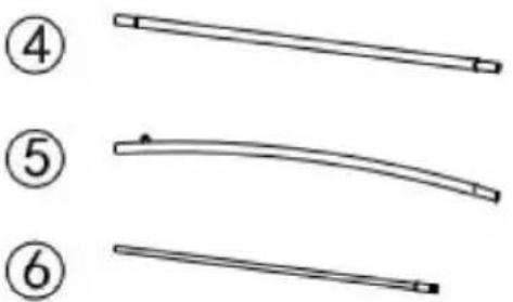
X2
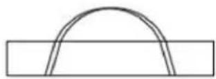
natural_image
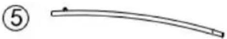
Two curved line segments labeled ⑤ and ⑥, no text or symbols presentX2

ASSEMBLÉE
1


natural_image
Technical line drawing of a structural frame with six circular insets showing different component views (no text or symbols)X2 X2 X1 X2 X2 X2

X1 X1 X4 X4 X4
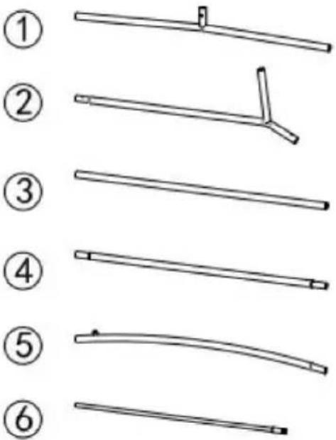
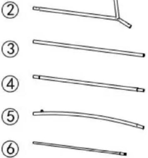
MONTAGGIO
1


natural_image
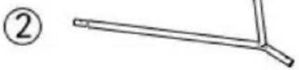
Technical line drawing of a structural frame with multiple circular insets showing different component views (no text or symbols)natural_image
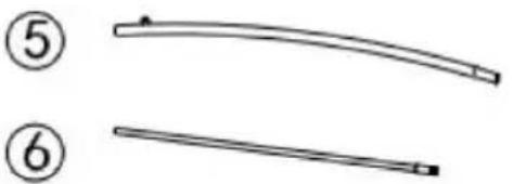
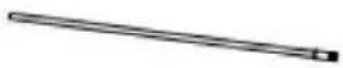
Simple line drawing of a Y-shaped tool or rod (no text or symbols)X2
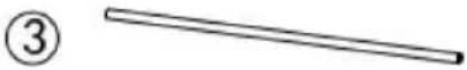
③
X1
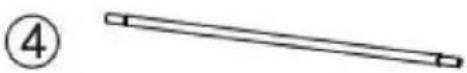
④
X2
⑤
X2
⑥
X2
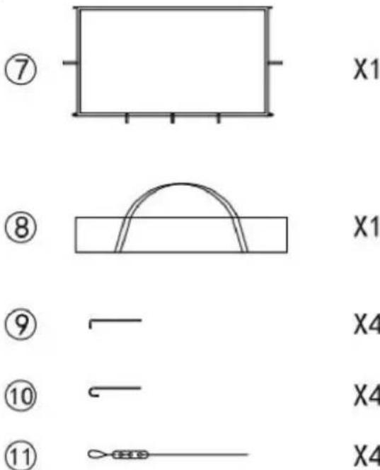
⑦
natural_image
Simple rectangular frame with four corner handles, no text or symbols presentX1
⑧
X1
⑨

X4
⑩

X4
⑪
X4
ASAMBLEA
1


natural_image
Technical line drawing of a structural frame with multiple circular insets showing different component views (no text or symbols)X2

X2
X1
X2
X2
X2
ÖSSZESZERELÉS
1


natural_image
Technical line drawing of a structural frame with multiple circular insets showing different component views (no text or symbols)X2

X2

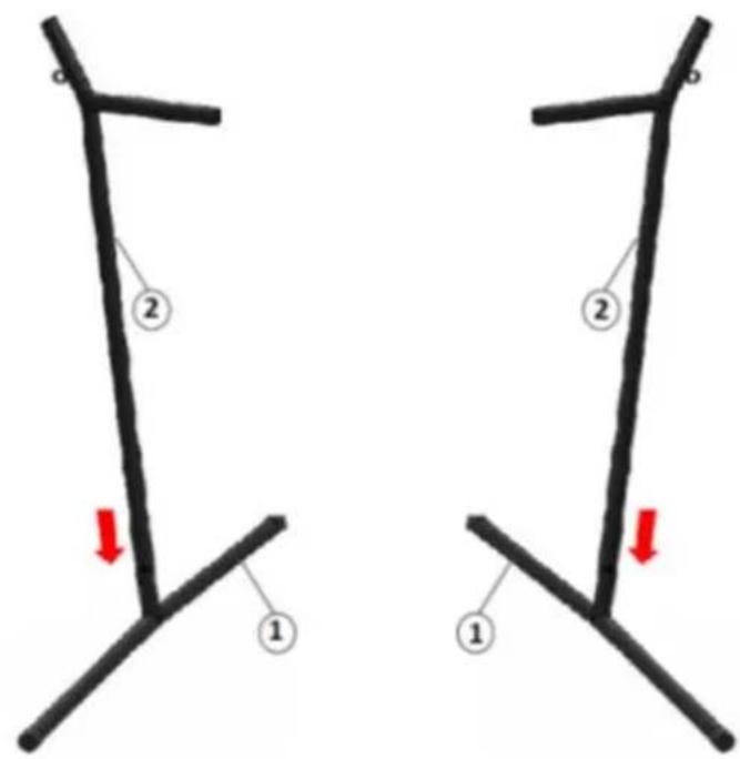
natural_image
Simple line drawing of a bent rod or rod with two ends, labeled with circled number 2 (no text or symbols on the object itself)X1

X2
X2
X2

MONTERING
OBS! Det anbefales, at mindst to personer samler den.
1


natural_image
Technical line drawing of a structural frame with six circular insets showing different component views (no text or symbols)OUR CUSTOMERS' SATISFACTION IS OUR MAIN GOAL! PLEASE CONTACT US WITH QUESTIONS AT:
NASZYM GŁÓWNYM CELEM JEST SATYSFAKCJA KLIENTÓW W PRZYPADKU PYTAŃ PROSIMY O KONTAKT Z PRZEDSTAWICIELEM W DANYM KRAJU:
NAŠÍM HLAVNÍM CÍLEM JE SPOKOJENOST NAŠICH ZÁKAZNÍKŮ! V PŘÍPADĚ OTÁZEK NÁS PROSÍM KONTAKTUJTE NA:
NOTRE BUT PREMIER EST VOTRE SATISFACTION! POUR TOUTE QUESTION, CONTACTEZ NOUS SUR: