
D271055 - Miter saw DEWALT - Free user manual and instructions
Find the device manual for free D271055 DEWALT in PDF.

| Accessory type | Sliding table for miter saw |
| Brand | DeWalt |
| Model | D271055 |
| Weight | 24 kg |
| Support rail dimensions (L x W) | 190 x 1430 mm |
| Sliding table dimensions | 400 x 260 mm |
| Guide length | 1500 mm |
| Compatible blade length | 900 mm |
| Use | Extends miter saw flexibility for straight and miter cuts |
| Safety | Wear safety glasses, keep children away, use a dust extractor |
| Assembly | On DeWalt D27105 miter saw in bench mode, to the left of the machine |
| Adjustment | Table height, parallelism, miter angle |
| Lubrication | No lubrication needed |
| Cleaning | Soft cloth regularly |
| Warranty | 30-day satisfaction, 1 year free maintenance, 1 year manufacturing defect |
| Package contents | Support rail, sliding table, guide, brackets, mounting accessories, Allen key, manual |
Frequently Asked Questions - D271055 DEWALT
User questions about D271055 DEWALT
0 question about this device. Answer the ones you know or ask your own.
Ask a new question about this device
Download the instructions for your Miter saw in PDF format for free! Find your manual D271055 - DEWALT and take your electronic device back in hand. On this page are published all the documents necessary for the use of your device. D271055 by DEWALT.
USER MANUAL D271055 DEWALT
D
E
F1
natural_image
Technical line drawing of a mechanical assembly with no visible text or symbolsF2
G

UDTRÆKSBORD D271055
Tillykke!
You have chosen a DEWALT product. Years of experience, thorough product development and innovation make DEWALT one of the most reliable partners for professional users.
Technical data
| D271055 | |
| Sliding table support rail (width x length) mm 190 x 1430 | |
| Sliding table mm 400 x 260 | |
| Fence mm 1500 | |
| Cutting length mm 900 | |
| Weight kg 24 | |
The following symbols are used throughout this manual:

Denotes risk of personal injury, loss of life or damage to the tool in case of non-observance of the instructions in this manual.
Manufacturer's declaration

D271055
DEWALT declares that this unit has been designed in compliance with 98/37/EEC.
This unit must not be put into service until it was established that the Power Tool to be connected to this unit is in compliance with 98/37/EEC (identified by the CE-marking on the Power Tool).
Director Engineering and Product Development Horst Großmann

D-65510, Idstein, Germany
Safety instructions
Observe the safety regulations in the instruction manual of the Power Tool to be connected to this attachment. Also observe any applicable additional safety rules. Read the following safety instructions before attempting to operate this product.
Keep these instructions in a safe place!
General
1 Keep work area clean
Cluttered areas and benches can cause accidents.
2 Keep children away
Do not let children come into contact with the tool or its attachments. Keep all people away from the work area.
3 Dress properly
Do not wear loose clothing or jewellery. They can be caught in moving parts. Preferably wear rubber gloves and non-slip footwear when working outdoors. Wear protective hair covering to keep long hair out of the way.
4 Wear safety goggles
Also use a face or dust mask in case the operations produce dust or flying particles.
5 Beware of maximum sound pressure
Take appropriate measures for the protection of hearing if the sound pressure of 85 dB(A) is exceeded.
6 Stay alert
Watch what you are doing. Use common sense. Do not operate the tool when you are tired.
7 Use appropriate tool
The intended use is laid down in this instruction manual. Do not force small tools or attachments to do the job of a heavy-duty tool. The tool will do the job better and safer at the rate for which it was intended.
Warning! The use of any accessory or attachment or performance of any operation with this tool, other than those recommended in this instruction manual may present a risk of personal injury.
8 Have your Power Tool Attachment repaired by an authorized DeWALT repair agent
Repair of your Power Tool Attachment being a matter of precision and skill, always take it to your DEWALT Authorized Repair Agent.
Additional safety instructions for sliding tables
The attention of UK users is drawn to the „woodworking machines regulations 1974“ and any subsequent amendments.
- Always mount the sliding table in conformity with the present instructions.
- Do not use the sliding table outdoors in the rain or in a damp environment.
- The sliding table must be stable at all times.
- Keep the work top clear of foreign objects.
- Use the sliding table only with the power tools and accessories specified in this manual.
- Remove any nails, staples and other metal parts from the workpiece.
- Use sharp and undamaged accessories only.
- Keep the sliding table clean and in good condition for better and safer performance. Follow the instructions for maintenance. Keep all controls dry, clean and free from oil and grease.
- As woodworking produces dust and woodchips, the use of dust extraction equipment is recommended.
- Whenever possible, connect a dust extraction device designed in accordance with the relevant regulations regarding dust emission.
Package contents
The package contains:
1 Sliding table support rail
1 Sliding table
1 Fence
2 Mounting brackets
1 Plastic bag containing:
1 fence setting guide
2 squares
1 hook
1 material support
1 measuring tape
1 Plastic bag containing:
1 Allen key
2 washers
2 socket head bolts
2 M8 nuts
1 Plastic bag containing:
1 securing/adjusting hook
1 Instruction manual
1 Exploded drawing
- Check for damage to the tool, parts or accessories which may have occurred during transport.
- Take the time to thoroughly read and understand this manual prior to operation.
Description (fig. A)
Your sliding table D271055 has been designed to extend the versatility of your DEWALT flip-over saw in saw bench mode. This attachment fits to the left-hand side of the machine and is used for straight and mitre crosscuts. In order to gain maximum capacities, the sliding table support rail can be positioned either in the rear position or in the forward position, or anywhere in between.
1 Sliding table support rail
2 Sliding table
3 Mitre quadrant
4 Fence
5 Mitre scale
6 Fence setting guide
Assembly

Do not mount this attachment to any other machine than the DEWALT D27105 in saw bench mode. Also refer to the instruction manual of your flip-over saw.
The mounting brackets (fig. B)
- Place the rear mounting bracket (7) onto the strip (8) and secure it with the socket head bolt (9) and nut (10).
- Mount the front mounting bracket in the same way.
The securing/adjusting hook (fig. C2 - C3)
- Insert the bushing (11) into the hole (12) in the frame (fig. C1).
- Place the lock bracket (13) onto the frame around the bushing.
- Pass the bolt (14) through the bracket and the bushing into the threaded hole on the opposite side of the bushing.
- Tighten the bolt to secure the bracket.
- Slacken the bolts (16) and (17) and slide the securing/adjusting hook (15) to the middle of the sliding table support rail (1) (fig. C2).
- Tighten the bolts temporarily.
- Press the hinge rail (18) of the sliding table into the mounting brackets (7) (fig. C3).
- Swivel the support rail (1) to horizontal position making sure that the fork (19) slides over the lock bracket (13) (fig. C4). Adjust the position of the securing/adjusting hook and the lock bracket as necessary.
- Rotate the securing hook (20) onto the lock bracket (13) and turn on the star grip (21) (fig. C5).
- Adjust the star grip (22) (fig. C3).
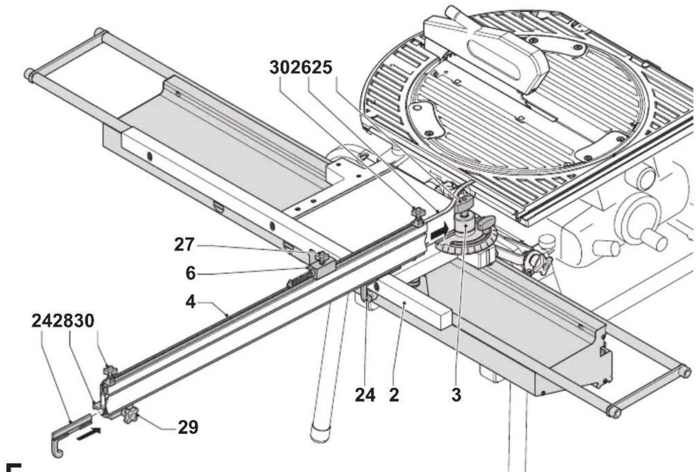
The sliding table (fig. D)
- Carefully engage the bearings (23) onto the right-hand support rail and swivel the sliding table to horizontal position to engage the other bearings on the left-hand support rail.
The fence (fig. E)
- Insert the 90^ guide piece (24) into the fence (4), engaging it into the groove of the sliding table (2).
- Engage the fence (4) into the mitre quadrant (3) up to 1 cm before the blade and tighten the wingnut (25).
- Introduce the measuring tape (26) into the top of the fence.
- Cut off any excess tape at 1 cm.
- Slide on the fence setting guide (6) and lock the star knob (27) temporarily.
- Slide on the material support (28) and lock the star knob (29) temporarily.
- Slide on the squares (30) and lock their star knobs temporarily.
Adjustment
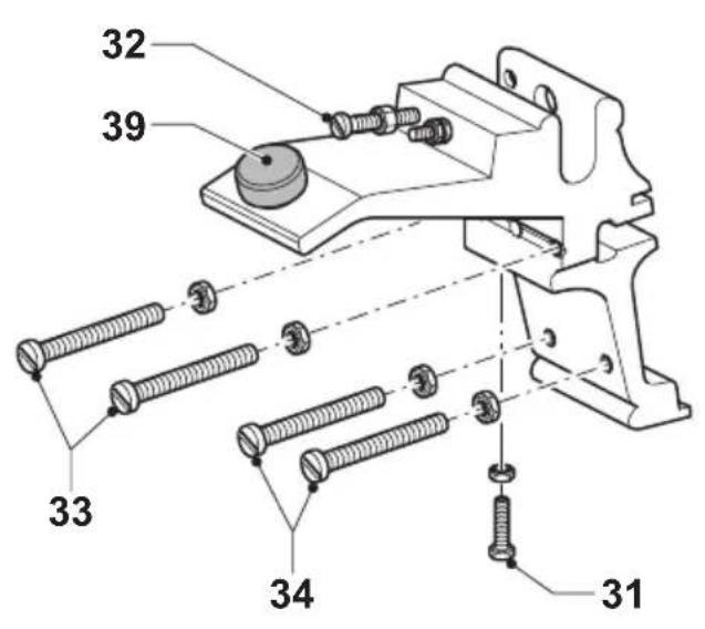
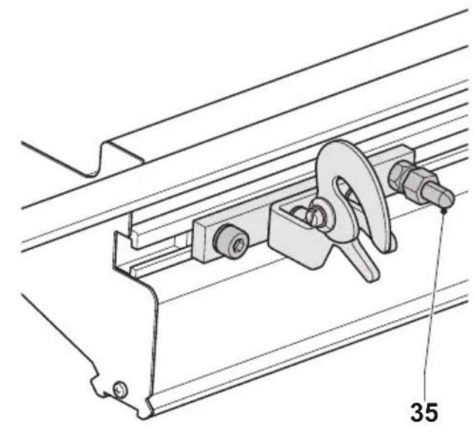
Checking and adjusting the table tops (fig. F1 & F2)
The following procedure assumes that the side panels of the mitre saw are parallel to each other. If the side panels need readjustment due to mobile usage, proceed as follows:
- Fold the legs of the mitre saw.
- Loosen the side panel screws.
- Place the mitre saw on a flat surface.
- Tighten the side panel screws.
- Slide the fence (4) over the table top of your sawing machine to the rear.
- If adjustment is required, proceed as follows:
- Use the bolt (31) and nut for height adjustment (fig. F1).
- Use the upper bolt (32) and nut to lock the mounting rail.
- Use the set screws (33) and (34) to set the table parallel to the blade of your sawing machine.
- Use the protruding bolt (35) and nut to set the sliding table level with the mitre saw table (fig. F2).
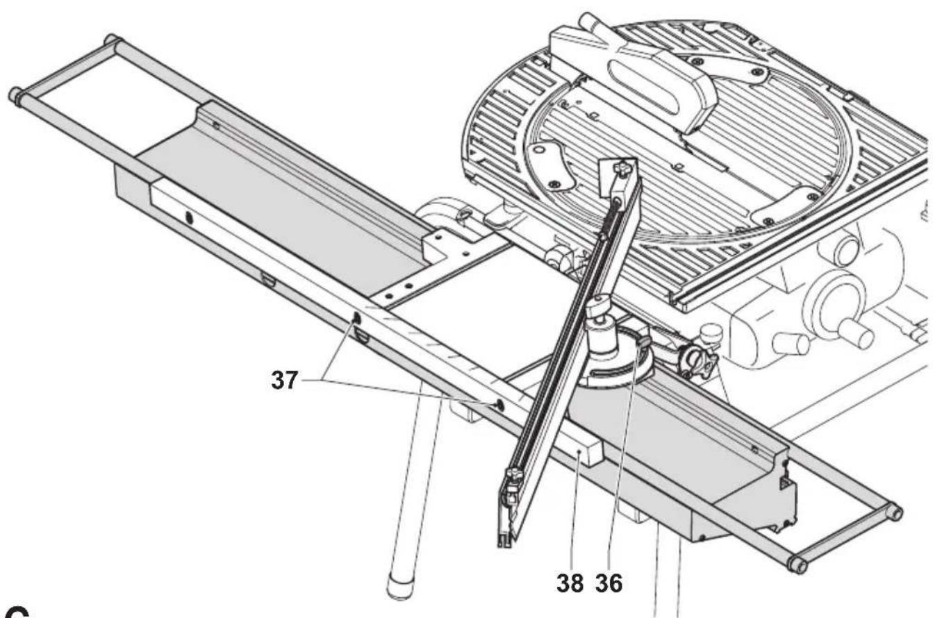
Angle adjustment (fig. G)
- Set the parallel fence to a known angle and lock the wingnut (36).
- If the angle adjustment is incorrect, loosen the Allen screws (37) in the side of the angle beam (38), adjusting it with the aid of a 45^ triangle or the 90^ guide piece (24). Fasten the Allen screws (37).
Instructions for use

Always observe the safety instructions and applicable regulations.
Prior to operation:
- Check that the sawing machine is correctly installed in saw bench mode.
- Check that all guards and fences are in perfect working order and mounted correctly.
- Check again that both tables are perfectly parallel.
- Connect a dust extractor.
Switching on and off

Refer to the instruction manual of your power tool.
Vertical straight cross cut (fig. E & H)
- Set the parallel fence (4) up to 1 cm before the blade. Engage the 90° guide piece (24) in the groove of the sliding table (2) and lock the wingnut (25).
- Press the spring loaded fence setting guide (6) to set its distance on the fence to the tip of the blade and lock the star knob (27).
-
Adjust the tape to show 5 cm at the edge of the fence setting guide (6) and lock the tape (26) with the star knob (30). The tape measure (26) is now calibrated relative to the position of the saw blade.
-
Place your workpiece against the fence.
- Set the fence setting guide (6) using the tape measure (26) to cut the workpiece to the desired length.
- If required, rest the end of the workpiece on the material support (28).
- Push the sliding table (2) to the rear, feeding the material into the blade. Do not force.
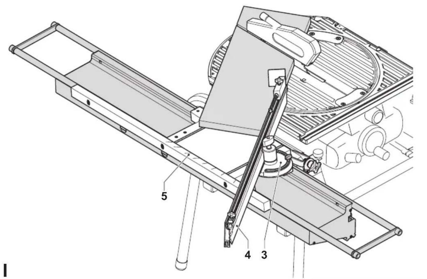
Mitre cuts (fig. 1)
- Disengage the 90^ guide piece from the groove of the sliding table.
- Set the required angle using the mitre quadrant (3) and scale (5).
- Make sure the parallel fence (4) will not be caught by the blade.
- Proceed as for a vertical straight cross-cut.
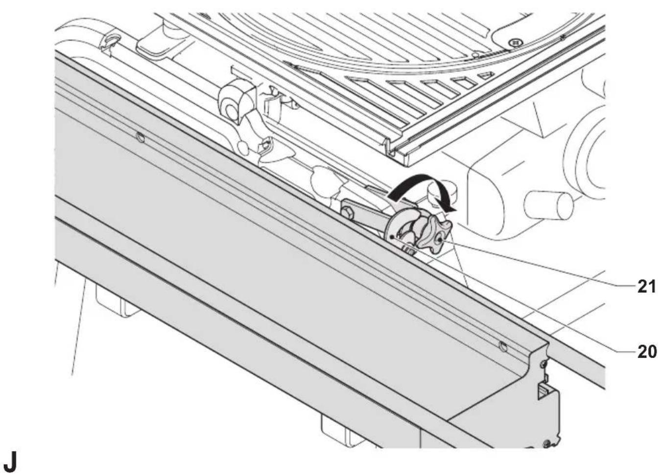
If the sliding table is not being used (fig. C1, F1 & J)
- Loosen the star grip (21), rotate the securing hook (20) up and hinge the sliding table down and out of the way (fig. J). The table now rests on the rubber stops (39) (fig. F1).
- Loosen the bolt (14) and rotate the bracket (13) down and out of the way (fig C1).
Maintenance
Your attachment has been designed to operate over a long period of time with a minimum of maintenance. Continuous satisfactory operation depends upon proper tool care and regular cleaning.

Lubrication
Your attachment requires no additional lubrication.

Cleaning
Regularly clean the attachment with a soft cloth.

Unwanted products and the environment
Take your attachment to an authorized DEWALT repair agent where it will be disposed of in an environmentally safe way.
GUARANTEE
• 30 DAY NO RISK SATISFACTION GUARANTEE •
If you are not completely satisfied with the performance of your DEWALT tool, simply return it within 30 days, complete as purchased, to the point of purchase, for a full refund or exchange. Proof of purchase must be produced.
• ONE YEAR FREE SERVICE CONTRACT •
If you need maintenance or service for your DEWALT tool, in the 12 months following purchase, it will be undertaken free of charge at an authorized DEWALT repair agent. Proof of purchase must be produced. Includes labour and spare parts for the attachments. Excludes accessories.
• ONE YEAR FULL WARRANTY •
If your DEWALT product becomes defective due to faulty materials or workmanship within 12 months from the date of purchase, we guarantee to replace all defective parts free of charge or, at our discretion, replace the unit free of charge provided that:
• The product has not been misused.
• Repairs have not been attempted by unauthorized persons.
• Proof of purchase date is produced.
This guarantee is offered as an extra benefit and is additional to consumers statutory rights.
For the location of your nearest authorized DEWALT repair agent, please use the appropriate telephone number on the back of this manual. Alternatively, a list of authorized DEWALT repair agents and full details on our after-sales service are available on the Internet at www.2helpU.com
MESA DESPLAZABLE D271055
¡Enhorabuena!
Director Engineering and Product Development Horst Großmann

L'emballage contient:
CARRELLO A SQUADRARE D271055
Congratulazioni!
Director Engineering and Product Development Horst Großmann

DeWALT, Richard-Klinger-Straße 11, D-65510, Idstein, Duitsland
Director Engineering and Product Development Horst Großmann

DeWALT, Richard-Klinger-Straße 11, D-65510, Idstein, Tyskland
Sikkerhetsforskrifter
Director Engineering and Product Development Horst Großmann

DeWALT, Richard-Klinger-Straße 11, D-65510, Idstein, Alemanha
Director Engineering and Product Development Horst Großmann

Director Engineering and Product Development Horst Großmann

DeWALT, Richard-Klinger-Straße 11, D-65510, Idstein, Tyskland
Säkerhetsinstruktioner

- UDTRÆKSBORD D271055
- Tillykke!
- Manufacturer's declaration
- Safety instructions
- General
- Keep work area clean
- Keep children away
- Dress properly
- Wear safety goggles
- Beware of maximum sound pressure
- Stay alert
- Use appropriate tool
- Have your Power Tool Attachment repaired by an authorized DeWALT repair agent
- Additional safety instructions for sliding tables
- Package contents
- Description (fig. A)
- Assembly
- The mounting brackets (fig. B)
- The securing/adjusting hook (fig. C2 - C3)
- The sliding table (fig. D)
- The fence (fig. E)
- Adjustment
- Checking and adjusting the table tops (fig. F1 & F2)
- Angle adjustment (fig. G)
- Instructions for use
- Prior to operation:
- Switching on and off
- Vertical straight cross cut (fig. E & H)
- Mitre cuts (fig. 1)
- If the sliding table is not being used (fig. C1, F1 & J)
- Maintenance
- Lubrication
- Cleaning
- Unwanted products and the environment
- GUARANTEE
- MESA DESPLAZABLE D271055
- ¡Enhorabuena!
- CARRELLO A SQUADRARE D271055
- Congratulazioni!
- Sikkerhetsforskrifter
- Säkerhetsinstruktioner
Brand : DEWALT
Model : D271055
Category : Miter saw