
DE3497 - Support table DEWALT - Free user manual and instructions
Find the device manual for free DE3497 DEWALT in PDF.

| Product type | Roller support table |
| Brand | DeWALT |
| Model | DE3497 |
| Length | 1100 mm |
| Width | 460 mm |
| Weight | 19 kg |
| Number of rollers | 3 |
| Roller width | 400 mm |
| Maximum stop length | 2150 mm |
| Power supply | None (manual accessory) |
| Main functions | Support for miter saws, circular saws, and saw benches; support rollers; guide ruler with length stop; cut extension |
| Assembly | Assembly of legs, ruler, stop, and accessories |
| Adjustment | Adjustable height, alignment of ruler and stop |
| Maintenance | No lubrication required |
| Safety | Follow safety instructions of the connected tool |
| Warranty | 30-day satisfaction, 1 year free maintenance, 1 year warranty against manufacturing defects |
| Spare parts and accessories | Optional accessories: machine legs, saw bench supports, etc. Available from dealer |
| Manual | Instruction manual and exploded drawing included |
Frequently Asked Questions - DE3497 DEWALT
User questions about DE3497 DEWALT
0 question about this device. Answer the ones you know or ask your own.
Ask a new question about this device
Download the instructions for your Support table in PDF format for free! Find your manual DE3497 - DEWALT and take your electronic device back in hand. On this page are published all the documents necessary for the use of your device. DE3497 by DEWALT.
USER MANUAL DE3497 DEWALT
 A2 A2 | [B1] | 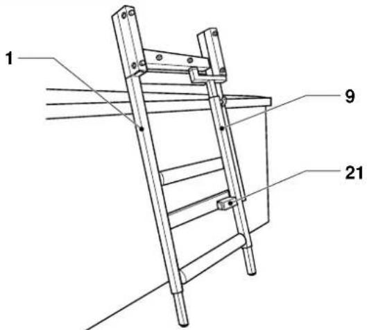 |
 B2 B2 | [C1] | 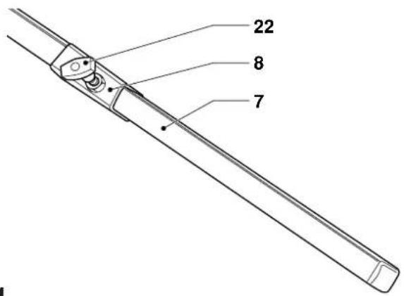 |
 C2 C3 C2 C3 | 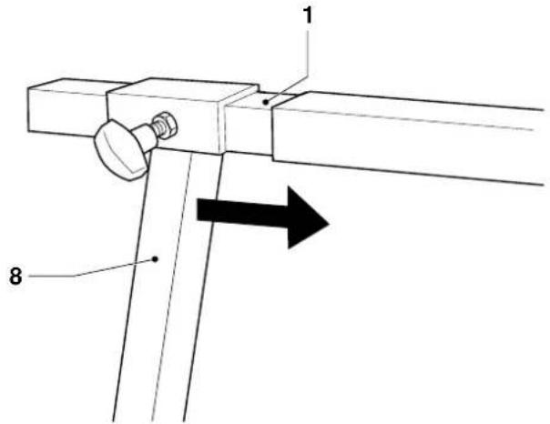 | |
 C4 C4 |
D1
E1
natural_image
Line drawing of a mechanical setup with a bracket and mounting base, no text or symbols presentE2
E4
F1
F2
G1
G2

natural_image
Technical line drawing of a mechanical device with ladder and support legs (no text or symbols)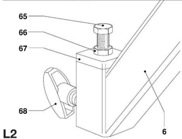
natural_image
Technical line drawing of a mechanical clamp or bracket assembly (no text or symbols)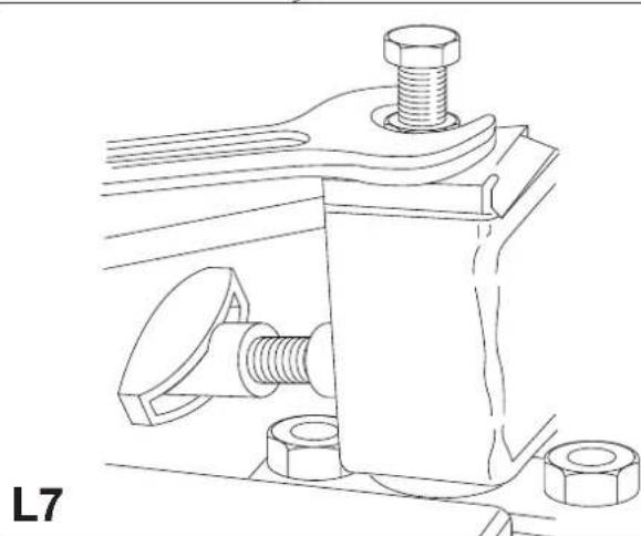
natural_image
Technical line drawing of a mechanical clamp or bracket assembly with bolts and nuts (no text or symbols)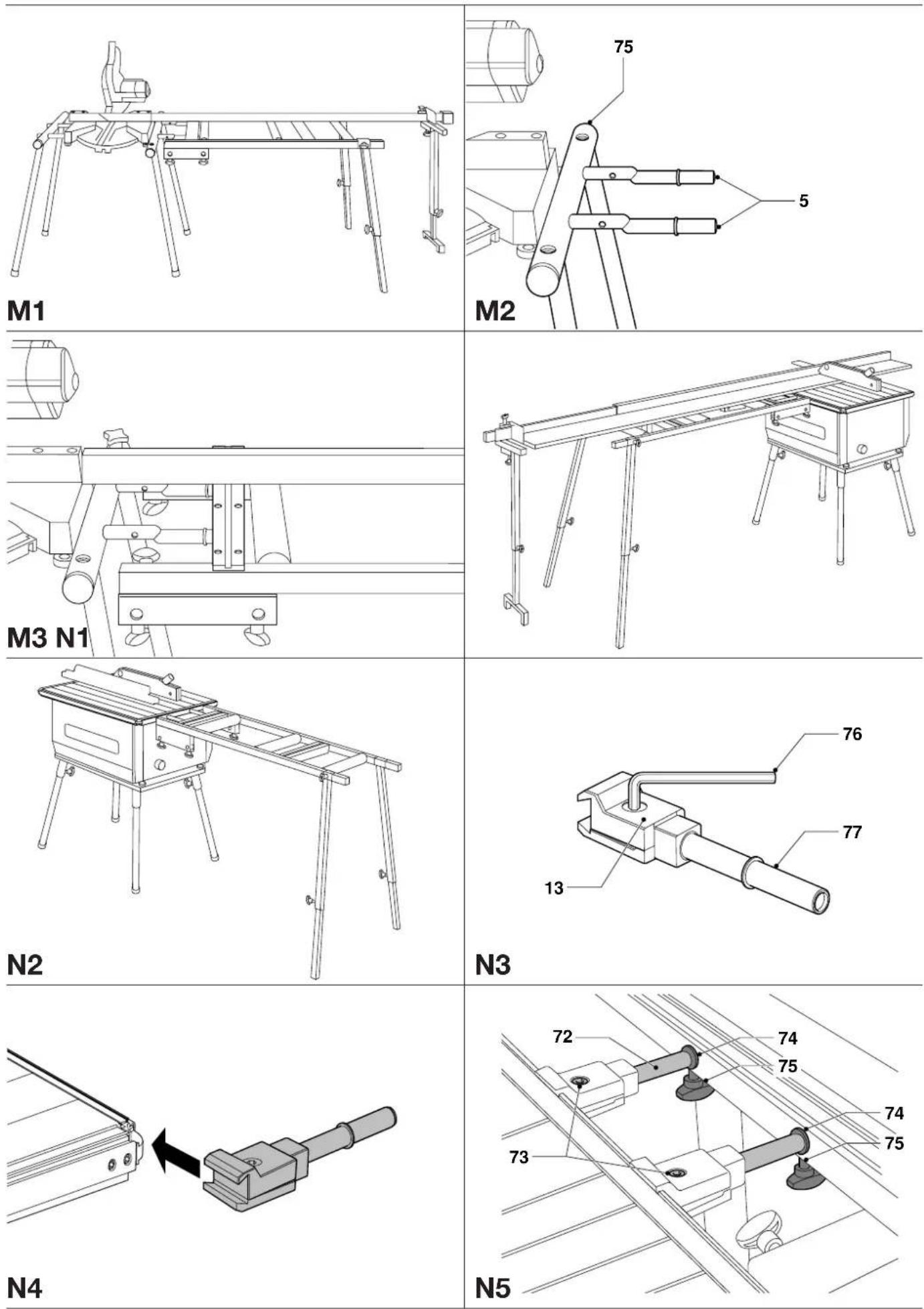
natural_image
Technical diagram of a mechanical assembly with a cylindrical component and rotating arrow, labeled N6 (no text or symbols on the diagram itself)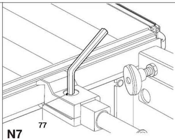
RULLEST∅TTEBORD DE3497
Tillykke!
You have chosen a DeWALT product. Years of experience, thorough product development and innovation make DeWALT one of the most reliable partners for professional users.
Table of contents
| Technical data en - 1 |
| Manufacturer's declaration en - 1 |
| Safety instructions en - 1 |
| Package contents en - 1 |
| Description en - 2 |
| Assembly and adjustment en - 2 |
| Maintenance en - 3 |
| Guarantee en - 4 |
Technical data
| DE3497 | |
| Length mm 1,100 | |
| Width mm 460 | |
| Number of rollers 3 | |
| Roller width mm 400 | |
| Maximum stop length | mm 2,150 |
| Weight kg 19 |
The following symbols are used throughout this manual:

Denotes risk of personal injury, loss of life or damage to the tool in case of non-observance of the instructions in this manual.
Manufacturer's declaration

DE3497
DEWALT declares that this unit has been designed in compliance with 89/392/EEC.
This unit must not be put into service until it was established that the Power Tool to be connected to this unit is in compliance with 89/392/EEC (identified by the CE-marking on the Power Tool).
Director Engineering and Product Development Horst Großmann
X. fopsmann
Observe the safety regulations in the instruction manual of the Power Tool to be connected to this attachment. Also observe any applicable additional safety rules. Read the following safety instructions before attempting to operate this product. Keep these instructions in a safe place!
General
1 Keep work area clean
Cluttered areas and benches can cause accidents.
2 Keep children away
Do not let children come into contact with the tool or its attachments. Keep all people away from the work area.
3 Dress properly
Do not wear loose clothing or jewellery. They can be caught in moving parts. Preferably wear rubber gloves and non-slip footwear when working outdoors. Wear protective hair covering to keep long hair out of the way.
4 Wear safety goggles
Also use a face or dust mask in case the operations produce dust or flying particles.
5 Beware of maximum sound pressure
Take appropriate measures for the protection of hearing if the sound pressure of 85 dB(A) is exceeded.
6 Stay alert
Watch what you are doing. Use common sense. Do not operate the tool when you are tired.
7 Use appropriate tool
The intended use is laid down in this instruction manual. Do not force small tools or attachments to do the job of a heavy-duty tool. The tool will do the job better and safer at the rate for which it was intended.
Warning! The use of any accessory or attachment or performance of any operation with this tool, other than those recommended in this instruction manual may present a risk of personal injury.
8 Have your Power Tool Attachment repaired by an authorized DeWALT repair agent
Repair of your Power Tool Attachment being a matter of precision and skill, always take it to your DeWALT Authorized Repair Agent.
Package contents
The package contains:
1 Partly assembled roller table frame
2 End legs, lower part
2 End legs, upper part
1 Guide fence with extension
2 Guide fence brackets
1 Cut-to-length stop
2 Irregular steel tubes
2 Split clamping brackets
2 Tube brackets
1 Cut-to-length extension support bracket
8 Star knobs
11 Locking knobs
6 Clamping screws M6 x 22
1 Clamping screw M6 x 30
1 Clamping screw M6 x 40
6 Flat washers M6
2 Bolts M8 x 50
4 Bolts M8 x 65
2 Hex nuts M8
2 Spacers M6
1 Tape clamp
1 Tape measure
1 Instruction manual
1 Exploded drawing
- Check for damage to the tool, parts or accessories which may have occurred during transport.
- Take the time to thoroughly read and understand this manual prior to operation.
Description (fig. A1 & A2)
Your DE3497 roller support table has been designed to extend the possibilities of your DEWALT crosscut/mitre saw, flip-over saw or saw bench.
Fig. A1
1 Main frame
2 Guide fence
3 Cut-to-length stop
4 Rollers
5 Steel tubes for crosscut/mitre saws (side mounting)
6 Tube brackets for crosscut/mitre saws (rear mounting)
7 Rear leg, lower part
8 Rear leg, upper part
9 Single support leg
10 Cut-to-length extension
11 Tape measure holder
12 Cut-to-length extension support bracket
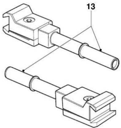
Fig. A2
13 Brackets for saw bench
Assembly and adjustment

Also refer to the manual of the machine to be used with this attachment.
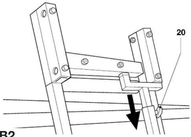
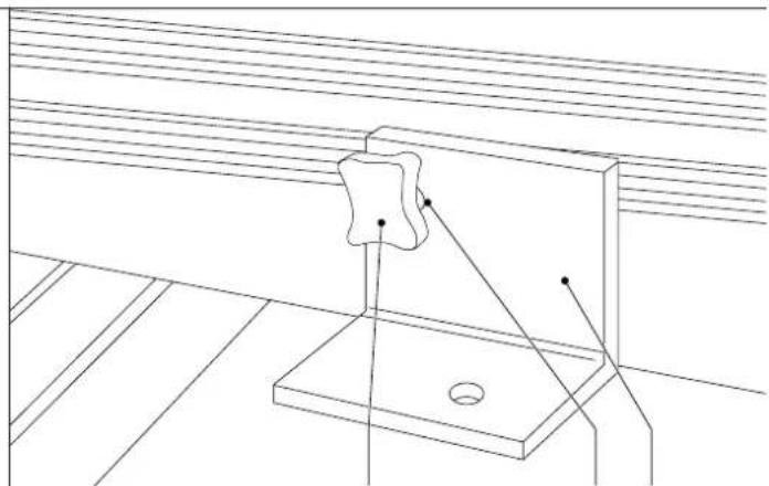
Removing the single support leg (fig. B1 & B2)
The single support leg (9) is clamped to the main frame (1) (fig. B1).
- Place the main frame against the workbench as shown (fig. B1) with the support leg pointing towards you.
- Slacken the locking knob (20).
- Pull the leg down to release it from the upper bracket.
- Remove the leg by sliding it out of the lower bracket (21).
Fitting the end legs (fig. C1 - C4)
- Insert the lower parts (7) into the upper parts (8) of the end legs (fig. C1).
- Insert a locking knob (22) into each of the upper parts.
- Expose the lower parts for approx. 40 cm and tighten the locking knobs.
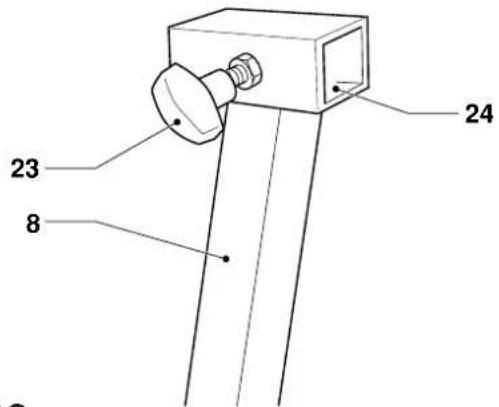
- Insert a locking knob (23) into the square socket (24) on the upper part of each leg (8) (fig. C2).
- Slide a leg (8) onto each side of the end of the main frame (1) (fig. C3). Note that the left and right legs are different. The locking knobs should be facing outwards, the legs should be angled outwards as shown (fig. C4).
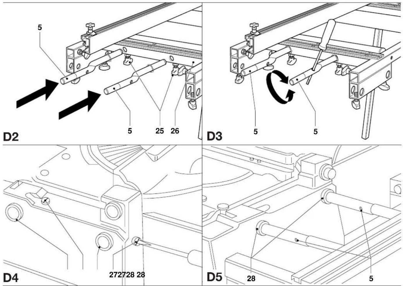
Mounting the roller support table to your flip-over saw in mitre saw mode (fig. D1 - D5)
The roller support table can be mounted either to the left or to the right of the saw (fig. D1). It is also possible to mount a roller support table to both sides.
- Insert two locking knobs (25) into the threaded sockets in the cross member (26) (fig. D2).
-
Insert the short, straight ends of the irregular steel tubes (5) into the holes in the cross member as shown and lightly tighten the locking knobs (25) (fig. D2).
-
Insert a screwdriver into the hole in the tubes as shown to rotate the tubes and align them with the holes (28) in the side of the base of your saw (fig. D3 & D4).
- Adjust the legs to approximately the correct height.
- Slacken the two locking knobs (27) in the base of the saw and move the table towards the saw, guiding the tubes (5) into the holes (28) (fig. D4 & D5).
- Insert only the bright turned end of the tubes into the saw base.
- Rotate the tubes until the table is correctly aligned with the saw table.
- Firmly tighten the locking knobs in the base of the saw and the locking knobs in the cross member.
- Set the legs to the correct height and tighten all locking knobs.
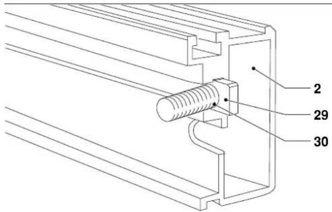
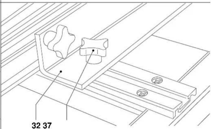
Mounting the guide fence (fig. A, E1 - E4)
The guide fence (2) is provided with a cut-to-length extension (10) (fig. A).
- Insert the foot of one of the clamping screws M6 x 22 (29) into the slot (30) in the fence (2) (fig. E1).
- Place the hole (31) in the upper left corner of the bracket (32) over the clamping screw (fig. E2).
- Place a flat washer M6 on the clamping screw and screw on a star knob (33).
- Mount the second bracket in the same way.
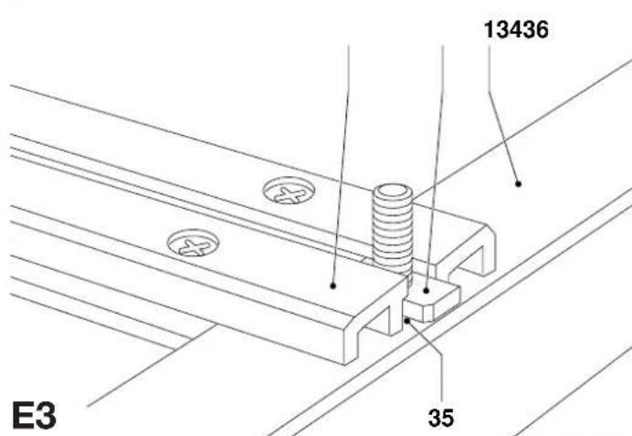
- Insert the foot of a clamping screw M6 x 22 (34) into the slot in each of the two struts (36) (fig. E3).
- Position the brackets (32) with the holes onto the clamping screws.
- Place a flat washer M6 on each of the clamping screws and screw on the star knobs (37) (fig. E4).
- Place and position the fence as required and tighten all clamping screws.
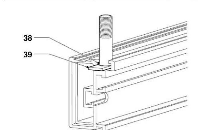
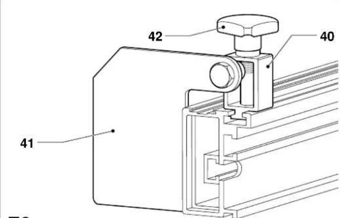
Mounting the cut-to-length stop (fig. F1 & F2)
The stop fits into the narrow slot (38) on top of the fence.
- Insert the foot of the clamping screw M6 x 40 (39) into the slot (38) (fig. F1).
- Place the bracket (40) holding the stop (41) onto the screw as shown (fig. F2).
- Place a flat washer M6 on the clamping screw and screw on a star knob (42).
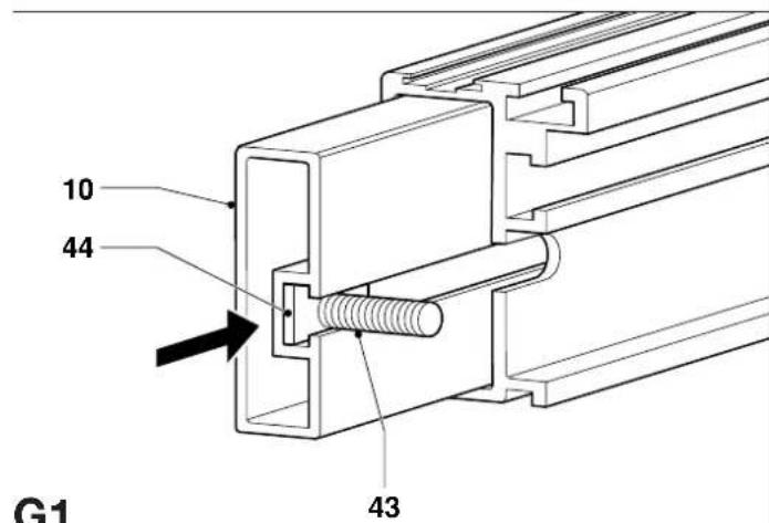
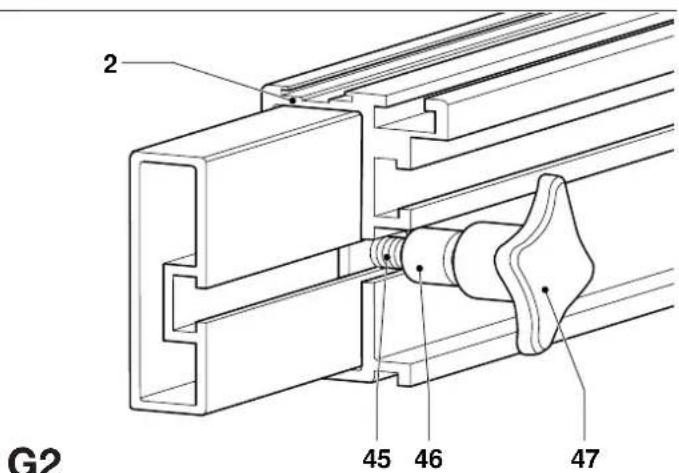
Mounting the cut-to-length extension support bracket (fig. G1 - G5)
This extension doubles the usable length of the cut-to-length stop. It can be mounted to either end of the cut-to-length extension as required.
- Pull out the cut-to-length extension (10) on the required end (fig. G1).
- Insert the foot of a clamping screw M6 x 22 (43) into the end of the slot (44) in the extension.
- Slide the clamping screw until it is located in the cut-out (45) in the fence (2) (fig. G2).
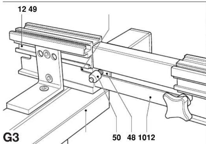
- Insert a locking knob into the socket on the underside of the support bracket.
- Insert the foot of a clamping screw M6 x 22 (48) into the fence extension (10) and slide the support bracket (12) onto the extension (fig. G3).
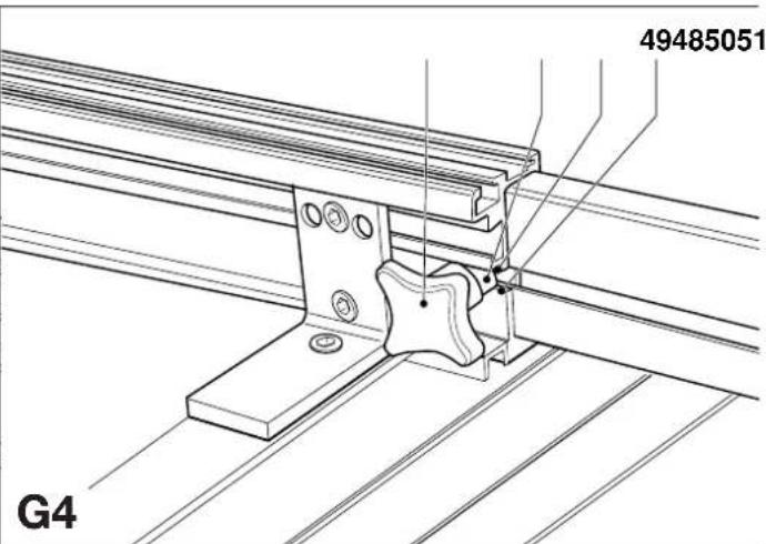
- Slide the clamping screw (48) to the rear until it engages in the cut-out (49) (fig. G4).
- Fit a spacer (50) and a star knob (51) and firmly tighten the star knob.
- Pull the extension out to the required distance and tighten the star knob on the fence.
- Insert the single leg (9) into the socket (52) under the bracket (12) and tighten the locking knob (53) (fig. G5).
- Adjust the height of the single leg.

The single leg must be fastened to the support bracket.
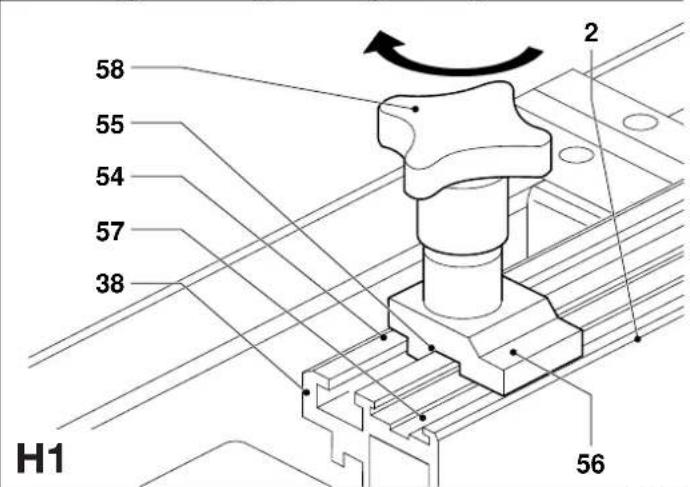
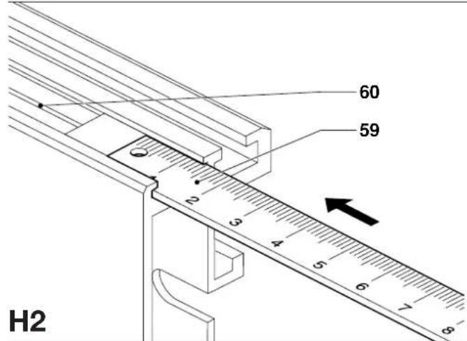
Mounting the tape measure (fig. H1 - H5)
- Insert the foot of the clamping screw M6 x 30 (54) into the narrow slot (38) on top of the fence (2) at the other end than the support bracket (fig. H1).
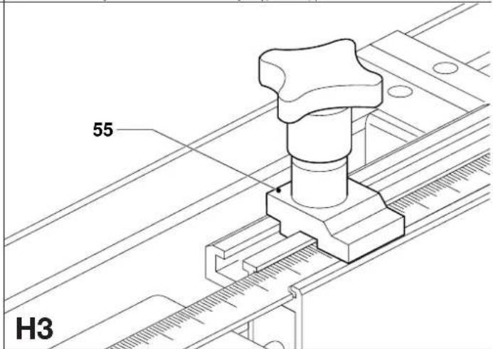
- Place the tape clamp (55) on the clamping screw with the flat clamping surface (56) down into the tape slide (57) (fig. H1).
- Place a flat washer M6 on the clamping screw and screw on a star knob (58).
- Insert the tape measure (59) into the slot (60) on the top of the fence and pull the tape to the front end of the fence (fig. H2).
- Position the tape correctly, taking into account the distance between the saw blade and the end of the fence.
- Clamp the tape using the tape clamp (55) (fig. H3).
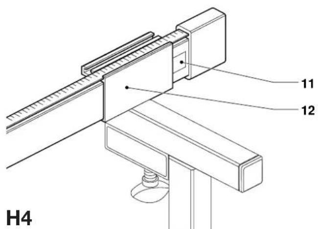
- Insert the tape measure holder (11) into the end of the bracket (12) (fig. H4).
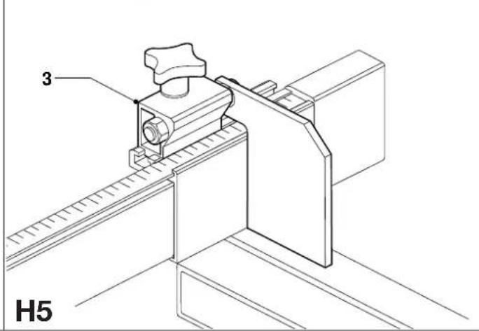
- Loosen the cut-to-length stop (3), slide it out of the fence and insert it into the extension support bracket (fig. H5).
Table adjustments
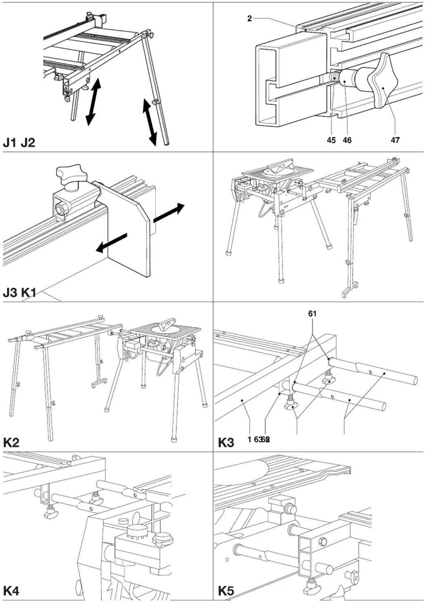
Height (fig. J1)
- After mounting the table to the saw, adjust the height by shortening or extending the legs.
- Check the adjustment using a level.
Fence (fig. J2)
- Loosen the fence support brackets and slide the fence to align it with the fence of the saw.
- Ensure that the fence is exactly parallel from end to end.
Cut-to-length stop (fig. J3)
- Slacken the star knob on the cut-to-length stop.
- Slide the stop along the fence to the desired position.
Mounting the roller support table to your flip-over saw in saw bench mode
Mounting to the side of the saw (fig. K1 - K6)
The roller support table can be mounted either to the left or to the right of the saw as in mitre saw mode. It can also be mounted parallel to the saw table as shown (fig. K1 & K2) to facilitate sawing large boards.
- Insert the short ends of the irregular tubes (5) into the corresponding holes (61) in the lower section (62) of main frame (1) (fig. K3).
- Insert two locking knobs (63) into the corresponding sockets and secure the tubes by tightening the knobs.
- Insert a screwdriver into the hole in the tubes to rotate the tubes and align them with the holes in the side of the base of your saw to connect as shown (fig. K4 & K5).
- Insert only the bright turned end of the tubes into the saw base.
- Rotate the tubes until the table is correctly aligned with the saw table.
- Firmly tighten the locking knobs in the base of the saw and the locking knobs in the table.
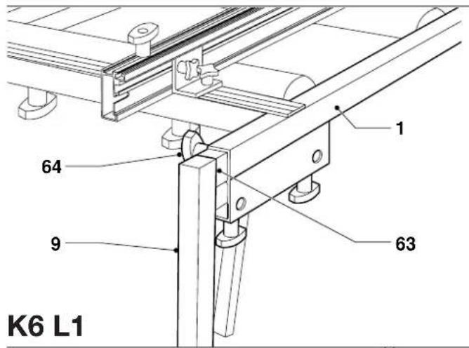
- Mount the single support leg (9) to the outer corner of the main frame by inserting the right angled piece (63) as shown (fig. K6).
- Secure the single support leg using a locking knob (64).
- Set the legs to the correct height and tighten all locking knobs.
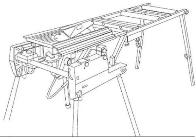
Mounting to the rear of the saw (fig. L1 - L7)
The table can also be mounted to the rear of the saw to support the workpiece after sawing (fig. L1). It is possible to combine this configuration with tables mounted to the sides of the saw.
- Remove the fence (if mounted).
- Take the two bolts M8 x 50 (65) and screw the hex nuts M8 approximately halfway (fig. L2).
-
Screw the bolts into the top of the square section (67) on the end of each bracket (6).
-
Insert two locking knobs (68) into the fronts of the square section as shown (fig. L2).
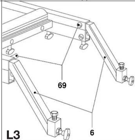
- Fully insert the plain ends of the tube brackets (6) into the end of the mainframe and insert two locking knobs (69) into the sides to secure the brackets (fig. L3).
- Position the table to the rear of the saw, aligning the centre of the front end with the saw blade.
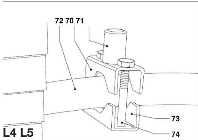
- Place the upper parts (70) of the split clamping brackets with the spigot (71) on the top of the rear linking bar (72), one to each side, aligning them with the tube brackets.
- Place the lower parts (73) of the brackets onto the upper parts from below (fig. L4).
- Secure the brackets using two bolts M8 x 65 (74) each. Lightly tighten the bolts.
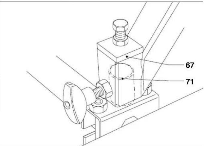
- Lift the table and place the sockets (67) over the spigots (71) (fig. L5).
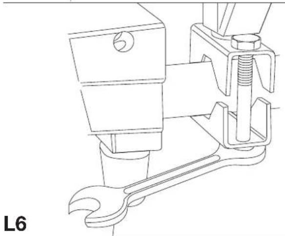
- Loosen the split clamping brackets and adjust them to obtain a good fit (fig. L6).
- Securely tighten the bolts.
- Screw the two height adjustment bolts in the top in or out as required (fig. L7).
- Securely tighten the locking nuts and locking knobs.
- Adjust the height of the legs as described above.
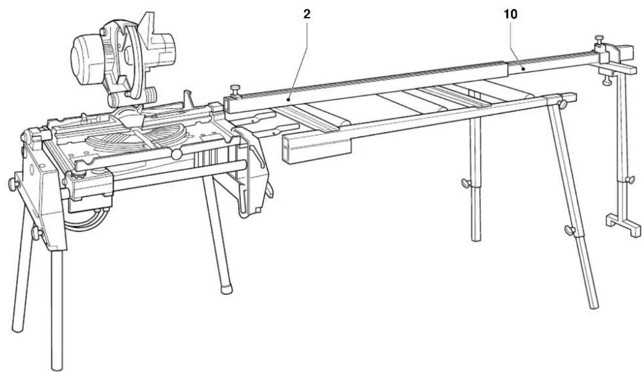
Mounting the roller support table to your crosscut/mitre saw (fig. M1 - M3)
Mounting the table to your crosscut/mitre saw requires the use of the machine legstand available as an option (fig. M1).
- Refer to the appropriate instructions for assembling the legstand.
- On the side where the table is to be mounted, remove the short support bars provided with the legstand.
- Insert the longer end of the tubes (5) through the upper cross support (75) of the legstand and into the holes in the side of the machine (fig. M2).
- Lightly tighten the locking knobs in the machine base.
- Position the cross support as close to the saw as possible.
- Insert the ends of the irregular tubes into the socket holes in the front of the cross member (fig. M3).
- Rotate the tubes until the table is correctly aligned with the saw table.
- Firmly tighten all locking knobs.
- Adjust the height of the legs.
- Place and position the fence as required.
Mounting the roller support table to your saw bench (fig. A2, N1 - N7)
Mounting the table to your saw bench requires the use of two brackets available as an option (fig. A2). The table can be mounted to the sides (fig. N1) or to the rear (fig. N2) of the saw bench.
• Take the brackets (13) and slacken the Allen screws (77) (fig. N3).
- Slide the brackets onto the dovetail at the appropriate side of the saw bench (fig. N4).
- Insert the tube ends into the holes in the cross member as shown (fig. N5).
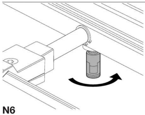
- Tighten the locking knobs in the cross member and adjust the height of the roller table as described above (fig. N6).
- Tighten the Allen screws (77) (fig. N7).
- Adjust the roller table fence as required.
Consult your dealer for further information on the appropriate accessories.
Maintenance
Your DeWALT attachment has been designed to operate over a long period of time with a minimum of maintenance. Continuous satisfactory operation depends upon proper tool care and regular cleaning.

Lubrication
Your attachment requires no additional lubrication.

Unwanted products and the environment
Take your attachment to an authorized DeWALT repair agent where it will be disposed of in an environmentally safe way.
GUARANTEE
• 30 DAY NO RISK SATISFACTION GUARANTEE •
If you are not completely satisfied with the performance of your DeWALT tool, simply return it within 30 days, complete as purchased, to the point of purchase, for a full refund or exchange. Proof of purchase must be produced.
• ONE YEAR FREE SERVICE CONTRACT •
If you need maintenance or service for your DeWALT tool, in the 12 months following purchase, it will be undertaken free of charge at an authorized DeWALT repair agent. Proof of purchase must be produced. Includes labour and spare parts for the attachments. Excludes accessories.
• ONE YEAR FULL WARRANTY •
If your DeWALT product becomes defective due to faulty materials or workmanship within 12 months from the date of purchase, we guarantee to replace all defective parts free of charge or, at our discretion, replace the unit free of charge provided that:
• The product has not been misused.
• Repairs have not been attempted by unauthorized persons.
• Proof of purchase date is produced.
This guarantee is offered as an extra benefit and is additional to consumers statutory rights.
For the location of your nearest authorized DEWALT repair agent, please use the appropriate telephone number on the back of this manual.
MESA DE SOPORTE DE RODILLOS DE3497
¡Enhorabuena!
Director Engineering and Product Development
Horst Großmann
X. fopsmann
L'emballage contient:
Director Engineering and Product Development Horst Großmann
X. fopsmann
DEWALT, Richard-Klinger-Straße 40, D-65510, Idstein, Duitsland
Director Engineering and Product Development Horst Großmann
X. fopsmann
DeWALT, Richard-Klinger-Straße 40, D-65510, Idstein, Tyskland
Sikkerhetsforskrifter
Director Engineering and Product Development Horst Großmann
X. fopsmann
DeWALT, Richard-Klinger-Straße 40, D-65510, Idstein, Alemanha
Director Engineering and Product Development
Horst Großmann
X. fopsmann
Director Engineering and Product Development Horst Großmann
X. fopsmann
DeWALT, Richard-Klinger-Straße 40, D-65510, Idstein, Tyskland
Säkerhetsinstruktioner
6 Spännskruvar M6 x 22
1 Spännskruv M6 x 30
1 Spännskruv M6 x 40
6 Platta brickor M6
2 Bultar M8 x 50
4 Bultar M8 x 65
2 Muttrar M8