
CDF 30 - Hob CANDY - Free user manual and instructions
Find the device manual for free CDF 30 CANDY in PDF.




| Product type | Gas/electric hob |
| Brand | CANDY |
| Model | CDF 30 |
| Installation type | Built-in |
| Number of gas burners | 3 (Auxiliary, Rapid, Triple crown) |
| Number of electric zones | 1 (cast iron or ceramic glass depending on version) |
| Compatible gas types | Natural gas (G20), Butane (G30), Propane (G31) |
| Electric supply voltage | 230 V ~ 50 Hz |
| Maximum electrical power | Up to 1000 W or more depending on version |
| Appliance dimensions (W x D) | 600 x 500 mm (estimated) |
| Cut-out dimensions (W x D) | 560 x 490 mm (estimated) |
| Net weight | Approx. 10 kg |
| Surface material | Ceramic glass (electric zones), stainless steel/enamel (gas) |
| Color | Black or stainless steel depending on version |
| Safety functions | Safety valve on burners, residual heat indicator, automatic shut-off in case of overheating |
| Ignition | Integrated electronic (push-button) |
| Cleaning | Non-abrasive sponge, scraper for ceramic glass, no abrasive products |
| Spare parts available | Injectors, grates, glass cover, etc. |
| Warranty | 2 years (generally) |
| Installation class | Type 3 (gas), Type Y (electric) |
Frequently Asked Questions - CDF 30 CANDY
User questions about CDF 30 CANDY
0 question about this device. Answer the ones you know or ask your own.
Ask a new question about this device
Download the instructions for your Hob in PDF format for free! Find your manual CDF 30 - CANDY and take your electronic device back in hand. On this page are published all the documents necessary for the use of your device. CDF 30 by CANDY.
USER MANUAL CDF 30 CANDY
MULTIPURPOSE BUILT-IN HOBS
GB
INSTRUCTION MANUAL
BUILT-IN COOKTOPS
FR
USER MANUAL
BUILT-IN COOKTOPS
DE
INSTRUCTION MANUAL
BUILT-IN COOKTOPS
PT
● 2009/142/EC: Gas appliances
Important warnings and tips for use
- IMPORTANT! This manual constitutes an integral part of the appliance. It must be kept intact and within easy reach during the entire life of the cooktop. Please carefully read this manual and all the instructions contained herein before using the appliance. Keep any spare parts supplied with the appliance. Installation and all gas/electric connections must be carried out by a qualified technician in accordance with the manufacturer's instructions and in full compliance with current laws and safety regulations. This appliance is intended solely for domestic use and is designed for the following functions: cooking and reheating food. Any other use is considered as improper.
The manufacturer declines all liability resulting from poor installation, tampering, inexpert use and use for purposes other than those specifically stated.
- Check that the appliance has not been damaged during transport. Keep all packaging materials (plastic bags, polystyrene foam, nylon, etc.) away from children, as they are potentially dangerous.
- The packaging material is recyclable and marked with the recycling symbol.

Dispose of the appliance responsibly.
- This appliance is not intended for use by persons (including children) with reduced physical, sensory or mental capabilities, or lack of experience and knowledge, unless they have been given supervision or instruction concerning use of the appliance by a person responsible for their safety. Children should be supervised to ensure that they do not play with the appliance.
- Electrical safety can only be guaranteed if the product is connected to a suitable earth connection.
- After using the cooktop, ensure the indicator on the knob is turned to the "off" position.
- Should you decide not to use the appliance any longer, before scrapping it make it unusable in accordance with current environmental health and safety laws, ensuring any parts which might constitute a danger to children are rendered harmless.
- Warning: in case of disassembly, maintenance and cleaning of the appliance, be careful.
Please use suitable prevention and protection equipment.
- The label with technical specifications is placed under the bottom and in the manual. Do not remove it.
- Never place inflammable objects on the hob. FIRE HAZARD!
- When a cooking zone is turned off, it remains hot for a while. During this time avoid touching the hot zone.
- Do not use aluminium foil or plastic containers (the protective films are not suitable for this hob).
- If there is a drawer under the hob, it is advisable not to keep inflammable objects or spray cans in it.
- The power supply cable must never touch hot cooking zones, it might get damaged. The cooking zone and pan bottom must always be dry and clean.
- If you find cracks on the appliance; if the cooking zones are overheated; if the display or the knobs do not work, or if the hob turns off by itself: immediately turn off the appliance and call the assistance service. In case of any malfunction, do not attempt to repair the hob yourself, but contact the assistance service.
- Do not cook with empty pans, especially if they are enamelled or aluminium pans.
Pan bottoms and ceramic glass could be damaged. Use only stainless steel pots and pans.
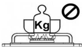
- Never place hot pans, frying pans, hard or pointed objects on the control panel, knobs area, or the frame.
- Sugar and other food with high sugar content will damage the hob. Any spilt food must be removed immediately with a scraper for glass. Warning! The optional scraper for glass has a sharp blade.
- The following damages will not affect the correct functioning or the stability of the appliance:
The formation of gelatinous residues due to melted sugar or food with a high sugar content; scratches due to salt, sugar, or sand grains, or rough pan bottoms; metal colour from pan stands.
- Only use warm water with a mild detergent. Do not use corrosive or abrasive products, as they could damage the surfaces. Warning: a steam cleaner is not to be used to clean the appliance.
- These instructions are valid only for those countries whose ID initials appear on the data plate found on the instructions handbook and on the appliance.
Declaration of Conformity
This appliance is in compliance with the following European Directives:
● 93/68/CE: General regulations ● 2006/95/CE: Concerning low tensions ● 2009/142/CE: Concerning gas appliances ● 89/336/CE: Electromagnetic compatibility - CE Regulation n°1935/2004: this appliance is suitable to come in contact with food products.
COOKTOP SPECIFICATIONS
Warnings:
This appliance is designed to be built into a housing unit.
- The installation class is type 3 for gas and type Y for electric parts.
- Housing units must be designed to withstand temperatures of up to 90°C or over.
- For correct installation, refer to the relevant paragraph and reference drawings.
- The use of a gas cooking appliance produces heat and humidity in the room in which it is installed. Ensure the kitchen is well ventilated: keep natural ventilation openings open, or install a mechanical ventilation device (extractor hood with exhaust duct). In the case of intensive or prolonged use of the appliance it may be necessary to provide additional ventilation, for example, by opening a window, or more efficient ventilation, for example by increasing the hood speed.
This handbook is valid for several types of cooktop.
Refer to the data plate on the back in order to identify the model that corresponds to your appliance.
These informations, together with the instructions and the illustrations in the following paragraphs will show you the characteristics of your appliance.
An Example:
| TRADE MARK(1) | |
| Type: (2) | W: (5)(6) V ~ Hz |
| Mod. (3) | |
| Art. (4) | |
| Ser. No. 00 00 0000 | Pin: |
| Cat.(7) G / mbar | |
| Σ Qn (kW): (8) | g/h: (9) |
| Made in EU 57 | CE001312 |
Legend:
(1) Trade Mark (2) Corresponding model (3) Technical code (4) Customer code (5) Power inputs (6) Voltage and frequency data (7) Country of target market and gas details (8) Gas burners power (9) Gas burners consumptions
USING THE COOKTOP
Gas burners
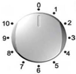
The delivery of gas to the burners is controlled by the knobs shown in fig.2 that in turn control the taps.
The symbols, depending on the various versions, may be printed over or under the knobs.
By moving the indicator to coincide with the printed symbols, the following adjustment can be made:
● Tap closed, no gas delivery
Maximum capacity, maximum gas delivery Minimum capacity, minimum gas delivery
Burners ignition
These models are equipped with safety valves which automatically shut off the gas delivery in the event the burner should, for any reason, go out. To relight the burner, turn the knob to position "tap closed" and repeat the ignition procedure following:
To ignite a burner, turn the gas tap knob to the maximum delivery position, then press and hold it down for about 4÷5 seconds.
Warnings:
- Once the burner is lit, adjust the flame by turning the knob to obtain the desired intensity. The setting must always be positioned between the maximum and minimum, and never
between the maximum setting and the off position.
- If the burner is difficult to light, or if the flame is tall or irregular, turn it off immediately by turning the knob to the "off" position and call the Assistance Service.
- If the particular nature of the local gas supply makes it difficult to ignite the burners with the knob turned to the maximum setting, repeat the operation without a pan in position and with the knob turned to the minimum setting and without pan stands.
- Warning: The ignition device must not be used for more than 15 seconds. If after this length of time the burner does not light, or if it goes out again accidentally, wait 1 minute before trying to ignite it again.
Grids
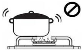
The panstand grids are designed to make the appliance easy and safe to use. Always check the panstand grids are properly positioned before using the appliance. Furthermore, always check the protective rubber feet are all present and correctly positioned.
◆ Grid for small pots or pans (optional - Fig.1A)
This is placed on top of the auxiliary burner grid (the smallest one) when pots or pans of reduced diameter are used, to avoid unbalancing.
♦ Special "WOK" support grid (optional - Fig.1B)
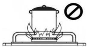
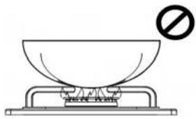
This is placed on top of the triple crown burner when using a “WOK” (concave bottom pan). In order to prevent serious malfunction of the burner, never use a wok without this special grid and never use the wok grid for flat bottomed pans.
Choosing the right burner
The symbols stamped on the control panel (fig.2) near the knobs indicate which knob corresponds to which burner. To choose the most suitable burner, take into account the diameter of the pan as well as the pan capacity (see table).
The diameter of the pan must be proportionate to the burner power in order to ensure high yield.
Pan diameter
| Burner | ∅ minimum | ∅ maximum | |
| A | Auxiliary | 60 mm (with reducer) | 140 mm |
| R | Rapid | 200 mm | 240 mm |
| TR | Triple-crown | 240 mm | 260 mm |
Electric hotplates
Warnings:
- Never cook food directly on the electric hotplates; always use suitable pots or containers.
- Absolutely do not leave the electric plates working without any pots on them. These wrong uses may cause overheating, damages to the appliance and fire hazard.
- Take all precautions possible to avoid spilling liquids onto the hotplate when it is hot.
- Do not use the appliance if the surface is broken or damaged; in case you find a crack on the appliance, disconnect immediately the electric supply and contact the After-Sales service.
- Bear in mind that the cooking zones remain hot for a relatively long time (about 30 min.) after switching off.
- Never clean with high-pressure water or steam-cleaning equipment.
- Do not put flammable materials (paper, plastic, etc.) on the cooking zones (plates or glass-ceramic).
- Do not allow heavy or sharp objects to fall on the glass-ceramic cook top.
- Do not stare at the halogen lamps on the cook top.
- Use flat bottomed pans only with a diameter large enough to cover the entire burner surface.
Switching on the hotplates:
To switch on the electric hotplate, turn the knob to the desired position.
Numbers 1 to 6 or 1 to 10 (fig.3), depending on whether the cooktop is fitted with a power switch or regulator, indicate the settings in progressing temperature (See Table).
When the electric hotplate is in operation an indicator LED on the control panel lights up.
Using the electric hotplates:
Once reached the heating required, adjust the power intensity, bearing in mind that the hotplate will continue to emit heat for several minutes after being switched off;
Depending on the food to cook, adjust the power intensity following the recommendations below:
| Knob position | Cooking type | |
| Switches figure 3/A | Regulators figure 3/B | |
| 0 | 0 | Off |
| 1 | 12 | For melting (butter, chocolate, etc..) |
| 2 | 34 | For keeping food warm or reheating small amounts of liquids |
| 3 | 56 | Reheating larger quantities, whipping creams and sauces |
| 4 | 78 | To simmering, soups, pasta, risottos, continuation of steaming, cooking steaks and fries in general |
| 5 | 89 | Browning meats, roast potatoes, fried fish and for bringing large quantities of water to a boil |
| 6 | 10 | Fast frying, grilled steaks, etc. |
Type of hotplates:
◆ solid plates (fig.17)
The cooktop may be equipped with a ∅145mm or a ∅180mm hotplate, conventional or rapid power.
The conventional hotplate is entirely black, while the rapid hotplate has a red dot in the centre.
Essentially, the rapid hotplate differs from the conventional one because it:
- offers greater power;
- reaches desired temperature more rapidly;
Some electric plates are equipped with a safety thermostat that reduces or disconnects power supply in case of overheating of the appliance (for example, if forgotten working).
♦ glass-ceramic hotplates (fig.19)
The glass-ceramic cooktop permits rapid vertical transmission of heat from the heating element below the cooktop to the pots or pans placed on top of it. Heat does not spread horizontally, thus at a distance of just a few centimeters from the cooking zone, the glass remains relatively cool to the touch. This appliance is equipped with a "residual heat" indicator that lights up if the temperature of the hob is above 70°C, even when turned off.
Residual heat persists for a relatively long time after the cooking zone has been switched off.
Absolutely do not touch the cooking areas or leave flammable objects near it until the lamp is off.
The indicator lamp turns off automatically once the temperature of the cooking zone falls below 70°C.
To start the extensible zone turn the knob over position "10" until a release is felt,
then turn the knob back and choose any position between 1-10 (energy regulation).
Glass-ceramic grill
Fig.18
This special grill glass has been designed for direct cooking on it (without pots or pans).
- Never use pots or pans, these could scratch the glass and damage the working;
- Aluminium film or papers are not suitable for this appliance;
- Do not use acid, toxic or corrosive cleaners, for safety and health. Just use a damp cloth and warm water.
Barbecue
Fig.18
To turn on the element, turn the knob clockwise; this sets the relative thermostat, with settings from "1" to "10". The pilot light turns on to show that the element is in operation.
It is normal for some types of lamp to show a little light even when the plates are not working. Using the grid: Before using the grid, it is always advisable to check that it is firmly positioned and correctly placed on the hob. Also check that the rubber pads it rests on are intact and properly in place. Lava rock: Place the rock inside the tray provided and dispose of the bag.
Once it is in place, turn on the heating element.
Fryer Fig.20
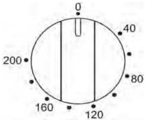
To set the cooking temperature, turn the knob clockwise, up to a maximum setting of 200°C.
When the heating element comes on, two lights, one green and one red, light up.
The red light goes out when the selected temperature is reached.
It is normal for some types of lamp to show a little light even when the plates are not working.
Advice and warnings: Put the frying oil in the container provided before switching on the heating element. After cooking, wait for the oil to cool before emptying the container. After cooking, turn knobs back to the "0" setting. If the regulator thermostat fails, a thermostat with manual reset will be activated; this must be reactivated by a skilled engineer.
INSTALLATION INSTRUCTIONS
Important!
- These instructions are intended for qualified technicians.
- The appliance must be installed correctly, in compliance with current laws.
- Before carrying out any operation on the appliance, it must be disconnected from the electric supply.
Fitting the appliance in the worktop
The cooktop may be fitted into any worktop, as long as it is heat resistant (minimum temperature of 90°C).
The dimensions of the hole to be made in the worktop and the minimum distances between rear and side walls and those above the appliance are shown in figure 4.
Isolation below (fig.6):
- If the cooktop is installed without an oven below it, a separator panel must be placed between the bottom of the cooktop and the housing below it, at a minimum distance of 10 mm.
- If the cooktop is installed over an oven, place a separator panel at a minimum distance of 15mm and follow the oven manufacturer's instructions, ensuring nonetheless sufficient aeration as specified in fig.6.
In any event, the electrical connection of the two appliances must be carried out
separately, both for electrical safety and to facilitate removal.
It is advisable to use an oven equipped with an internal forced cooling system.
Fixing the cooktop (fig.7):
To fix the cooktop in the housing, proceed as follows:
- Position the special gasket supplied [C] along the outer perimeter of the worktop, following the diagram shown in fig.4, so that the ends of the gasket meet exactly without overlapping.
- Position the cooktop into the worktop, taking care to ensure it is placed exactly in the centre.
- Fix the cooktop to the worktop using the special brackets supplied [A], as shown in fig.7.
Correct installation of the sealing gasket ensures complete protection against infiltration of liquids.
Installation area and removal of combustion fumes
The appliance must be installed and operated in suitable areas, and in compliance with current laws.
The installation technician must observe current laws governing ventilation and removal of combustion fumes. Please remind that the air required for combustion is 2m3/h per kW of power (gas) installed.
◆ Installation area
In the room where the gas appliance is installed, there must be a sufficient natural air supply to allow the gas to burn correctly (in conformity of currents laws).
The natural flow of air must take place through an opening made on an outside wall of the room and having a working section of at least 100 cm2 (A). In the case of appliances without safety valves, this opening must have a minimum working section of 200 cm2 (fig.8).
This opening must be made in such a way that it cannot be obstructed from inside or outside. It should be positioned near floor level, preferably on the side opposite the fume exhaust devices. If it is not possible to make the necessary openings, the air can be supplied from an adjacent, suitably ventilated room, as long as this room is not a bedroom, a dangerous area or a low pressure area.
♦ Removal of combustion fumes
Combustion fumes produced by gas appliances must be removed by means of a hood connected directly either to an exhaust duct or to the outside (fig.8).
If a hood cannot be installed, an electric extractor fan must be fitted to the outside wall or the window. This electric extractor fan must have a sufficient capacity to guarantee a change of air of the kitchen of at least 3-5 times its volume.
◆ Components shown in fig.8:
A Opening for air supply C Hood for exhaust removal of combustion fumes E Electric extractor fan for removal of combustion fumes
Connection to gas supply
Before installation, make sure the type and pressure of the local gas supply are compatible with the cooktop settings. To do this, check the data on the appliance data plate on the cooktop as well as on this handbook. The gas connection must be carried out by a qualified technician in compliance with local current laws. If using metal hoses, ensure these do not come into contact with any movable parts and are at no point crushed.
Carry out the connection in such a way as does not cause any stress whatsoever on the appliance.
The gas supply connector is threaded G 1/2" (fig.12).
For ISO R7 connections, the gasket is not required.
For ISO R228 connections, the washer supplied must be fitted.
After connection operations, check for leaks using a soapy solution.
Electrical connection
Before connecting the appliance to the electricity supply, check that the voltage corresponds to that on the data plate and that the power supply cable is suitable for the appliance load also stated on the data plate. If the appliance is connected directly to the mains, fit an all-pole disconnect switch with minimum contact gap of 3 mm, adequate for the appliance load and complying to regulations.
The plug used must support the power of work of the appliance.
Warnings:
- Do not use reducers, adapters or switches for connection to the mains, since these could overheat and cause burns.
- Earth connection is required by law (fig.10).
The manufacturer declines all liability resulting from failure to observe this regulation.
If the power cable must be replaced, use a cable having identical characteristics to the original supplied by the manufacturer, suitable for the load and temperature (type T90°C). This is available
from After-sales service. Furthermore, the end of the power cable to be connected to the appliance must have the Yellow-Green earth conductor 20 mm longer than the other conductors.
The cable must support the load of the appliance.
Refer to the table below for the size of the power cable.
| Cooktop type | Wire size |
| Only with gas burners | 0,75 mm2 |
| With electric plate(s) <= 1000W | 0,75 mm2 |
| With electric plate(s) >1000W | 1,50 mm2 |
| Barbecue / Fryer | 1,50 mm2 |
Should it be necessary to replace the supply cord,
connect the wire in accordance with the following colours/codes:
BLUE NEUTRAL (N)
BROWN LIVE (L)
YELLOW-GREEN EARTH ( 1/2)
- Check whether there is an omnipolar switch available on the domestic line which is compliant with current standards laws. Otherwise, place a device easily reachable between the appliance and the electricity line.
- If the cable result damaged, it must be quickly replaced with a new one by a qualified technician or call the After-Sales service.
ADJUSTMENT TO DIFFERENT TYPES OF GAS
If a different type of gas from the one indicated on the rating plate is used, the injectors must be replaced.
If spare injectors are not supplied with the appliance, they are available from the After-sales service.
For the choice of replacement injectors, refer to the injectors table at the end of this booklet.
The injectors are identified by their diameter, which is expressed in hundredths of mm, stamped on the body of the injector itself.
Replacing the injectors
- Remove the grids and burner caps from the cooktop
- Using a socket wrench, replace the injectors "J" (fig.9) with the suitable ones for the gas used
- Replace the burners
The burners do not require primary air adjustment.
Adjustment of minimum setting
After replacing the injectors, light the burner and remove the knob. Turn the tap to the minimum setting and insert a screwdriver in the rod: tighten to reduce the flame, loosen to increase the flame (fig.9)
For gas G30/G31, tighten the adjustment screw fully
The flame must result small, uniform and regular all around the burner crown.
Check that:
- quickly turn the knob from max. to min. position of gas power, the flame doesn't go over
- for burners with a safety device, the flame have to licks the thermocouple
- leaving the burner alight for a few minutes, it doesn't go over
CLEANING AND MAINTENANCE
To maintain the cooktop in optimum condition, clean it regularly after each use, allowing it to cool before cleaning.
- Never use abrasive or sharp substances or materials to clean the surfaces
- Never clean the appliance with high pressure water or steam cleaning equipment.
Do not use flammable or alcoholic cleaners.
Enamelled parts:
All enamelled parts should be cleaned with a sponge and soapy water or specific detergents.
Never use abrasive cleaning products. Dry thoroughly after cleaning.
Stainless steel top:
The stainless steel top should be cleaned with a damp cloth and proprietary detergents commercially available. After rinsing, dry preferably with a chamois leather.
Grids:
The enamelled panstand grids of the cooktop are dishwasher safe.
Stainless steel panstand grids may take on a bluish tinge on parts around the burners as a result of the high temperatures. This effect can be reduced by using commercially available steel wool pads.
Burners:
The burners, comprising two parts, can be removed and cleaned using suitable detergents.
After cleaning, dry the burners thoroughly and reposition them carefully in their seats.
In models with electric ignition, always check that the electrode "E" (fig.11) is clean.
In models with safety device, clean the probe "T" (fig.11) in order to allow regular operation of the safety valve. Both the electrode and probe must be cleaned with care.
Upon completion of cleaning, replace the burners accurately in their seats.
To prevent damaging the electric ignition, avoid using it when the burners are not in place.
Electric hotplates:
The electric hotplates should be cleaned when they are only slightly warm.
Clean with a damp cloth, then finish off with a cloth dampened with mineral oil.
In the glass-ceramic hobs never use abrasive cleaners, could damage the glass surface.
Use only neutral and not-flammable detergents.
Ceramic hob
The electric plates must be cleaned when they are just slightly warm. Clean with a damp rag and finish with a "scraper" (optional).
Maintenance
The appliances do not require any particular maintenance, nonetheless it is advisable to have them checked at least once every two years.
If the knobs become difficult to turn, or if there is a smell of gas, shut the gas supply tap and call
After-sales service. Faulty taps must be replaced along with their gasket.
Glass lid
If the hob has a glass lid, the following precautions must be adopted:
- Never place hot pans on the lid when closed.
- Remove any liquid spills before opening the lid.
- The lid may break if heated;
Turn off all burners and electric plates and wait for them to cool before closing it.
After-sales service
Before calling in the After-Sales Service
If the hob fails to operate, we advise you to:
- Check that the plug is correctly inserted into the power socket.
- Check that the flow of gas is normal
If you are unable to find the cause of the problem;
switch the appliance off, do not tamper with it and call in the After-Sales Service.
● 93/68/CEE: General Standards
● 2006/95/CE: Low Voltage
● 93/68/CE: General Standards
Fig-Abb-Rys-Ábra-Obr-Puc. 1/B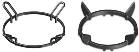
B
A B
C D E
| CDG31SPX | 510 | 290 | 270 | 490 | 45 |
| CDB30X | 510 | 290 | 270 | 490 | 45 |
| CDE32X | 510 | 290 | 270 | 490 | 45 |
| CDE32XDE | 510 | 290 | 270 | 490 | 45 |
| CDF30X | 510 | 290 | 270 | 490 | 145 |
| CDG32SPX | 510 | 290 | 270 | 490 | 45 |
| CDH32X | 510 | 290 | 270 | 490 | 45 |
| CDVG30X | 510 | 290 | 270 | 490 | 45 |
| F = ( N x B ) -20mm | Numero di piani da affiancareNumber of hobs to combineNombre de tables de cuisson a mettre côte a côteNúmero de encimeras a aparearNúmero de placas a pôr lado a ladoAnzal nebeneinander anzuordnender kochmulden |
Without oven With oven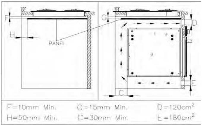
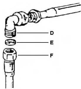
| ITGBFRDEESPT | Raccordo | Guarnizione | Tubo rigido o tubo flessibile |
| Union | Gasket | Pipe or hose | |
| Raccord | Joint | Tuyau rigide ou flexible | |
| Gewindeanschluss | Dichtung | Starres Rohr oder Metallschlauch | |
| Empalme de gas | Anillo | Tubo flexibile | |
| Conexão | Vedante | Tubo rígido e tubo flexível |
Fig. 13 Fryer – Friggitrice – Friteuse – Fritadeira – Freidora – Einbaufritteuse - Friteuse
| Knob | Mandos |
| anopola | Drehknöpfen |
| Bouton | Knoppen |
| lanípulo | knoflících |
Using – Uso – Utilisation – Gebrauch Gebruik - Použití - ЭКСПЛУАТАЦИЯ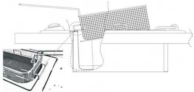
Fig. 14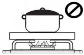
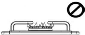
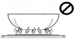
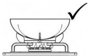
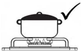
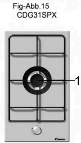
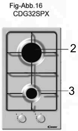
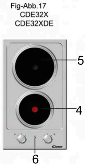
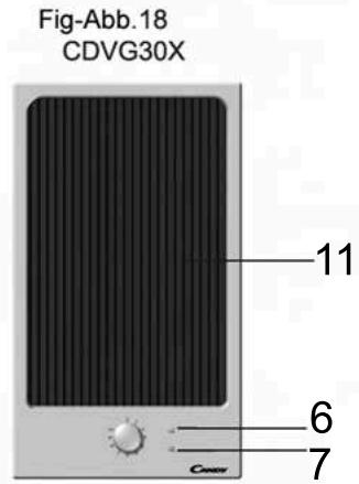
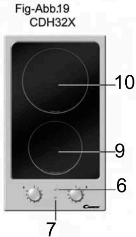
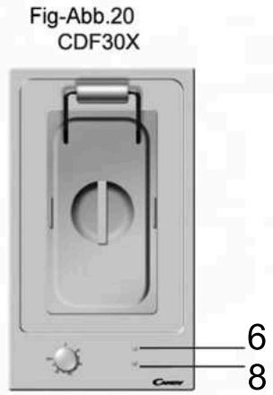
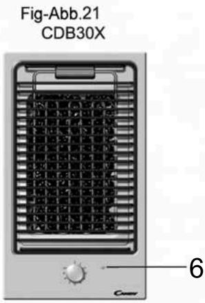
Componenti illustrati in figura 15-21:
Components shown in fig.15-21:

- INSTRUCTION MANUAL
- USER MANUAL
- IMPORTANT WARNINGS AND TIPS FOR USE
- DISPOSE OF THE APPLIANCE RESPONSIBLY
- PLEASE USE SUITABLE PREVENTION AND PROTECTION EQUIPMENT
- DECLARATION OF CONFORMITY
- COOKTOP SPECIFICATIONS
- WARNINGS
- LEGEND
- USING THE COOKTOP
- GAS BURNERS
- BURNERS IGNITION
- GRIDS
- CHOOSING THE RIGHT BURNER
- ELECTRIC HOTPLATES
- SWITCHING ON THE HOTPLATES
- USING THE ELECTRIC HOTPLATES
- TYPE OF HOTPLATES
- ◆ SOLID PLATES (FIG.17)
- ♦ GLASS-CERAMIC HOTPLATES (FIG.19)
- ABSOLUTELY DO NOT TOUCH THE COOKING AREAS OR LEAVE FLAMMABLE OBJECTS NEAR IT UNTIL THE LAMP IS OFF
- GLASS-CERAMIC GRILL
- FIG
- BARBECUE
- FRYER FIG
- INSTALLATION INSTRUCTIONS
- IMPORTANT
- FITTING THE APPLIANCE IN THE WORKTOP
- FIXING THE COOKTOP (FIG.7)
- INSTALLATION AREA AND REMOVAL OF COMBUSTION FUMES
- ◆ INSTALLATION AREA
- ♦ REMOVAL OF COMBUSTION FUMES
- ◆ COMPONENTS SHOWN IN FIG
- CONNECTION TO GAS SUPPLY
- ELECTRICAL CONNECTION
- ADJUSTMENT TO DIFFERENT TYPES OF GAS
- REPLACING THE INJECTORS
- ADJUSTMENT OF MINIMUM SETTING
- FOR GAS G30/G31, TIGHTEN THE ADJUSTMENT SCREW FULLY
- CLEANING AND MAINTENANCE
- ENAMELLED PARTS
- STAINLESS STEEL TOP
- BURNERS
- CERAMIC HOB
- MAINTENANCE
- GLASS LID
- AFTER-SALES SERVICE
Brand : CANDY
Model : CDF 30
Category : Hob