Split Easy Up - Basket Airforce - Free user manual and instructions
Find the device manual for free Split Easy Up Airforce in PDF.

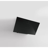
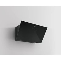
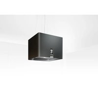
| Product type | Range hood |
| Brand | Airforce |
| Model | Split Easy Up |
| Max weight | 30 kg |
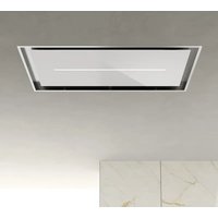
| Installation | False ceiling (built-in) |
| Motor type | Remote motor |
| Suction speeds | 6 speeds (including timed intensive 8 min) |
| Control | Radio remote control |
| Lighting | LED with Dimmable and Tunable White function |
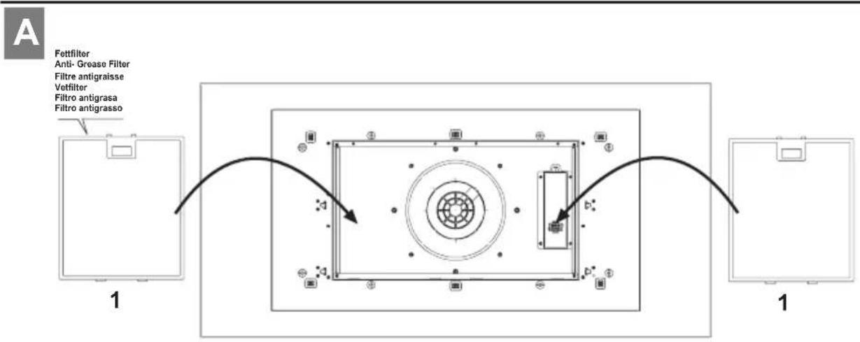
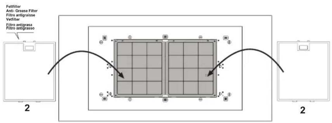
| Grease filter | Washable metal (monthly, dishwasher safe) |
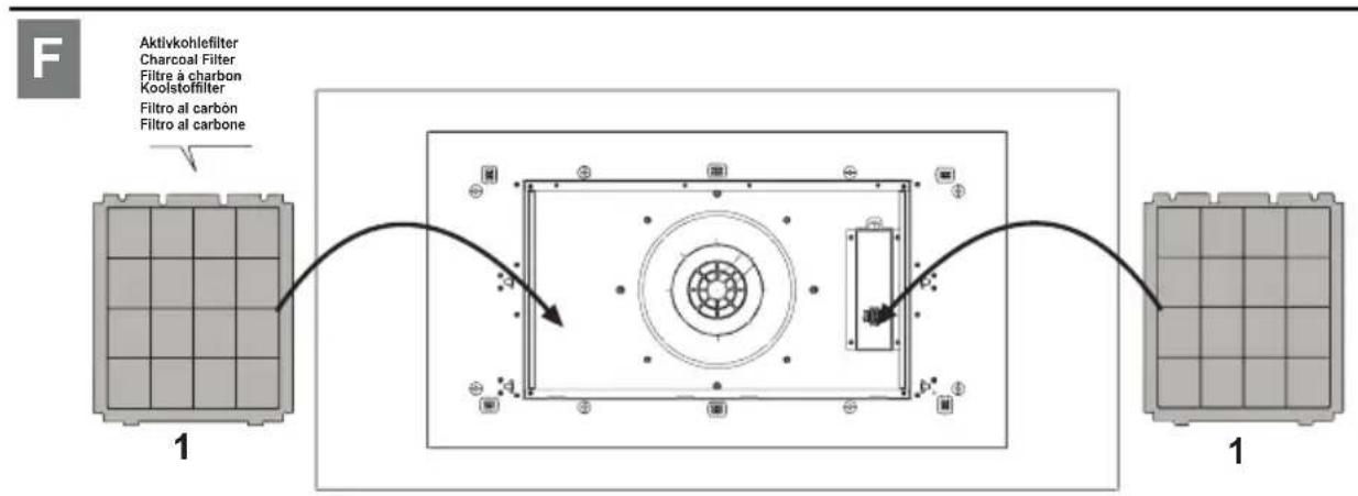
| Charcoal filter | Active, non-washable, replace every 6 months |
| Timer | Yes (5 minutes) |
| Minimum safety distance | 65 cm (electric or gas cooking) |
| Electrical supply | 220-240 V |
| Power cable length | 1250 mm |
| Safety function | General shutdown, protection against radio interference |
| Exterior maintenance | Cloth soaked in denatured alcohol or neutral detergent |
| Protection index | 30 mA residual current device required |
| Tested performance | Compliant with IEC 61591, EU regulation 65/2014 |
Frequently Asked Questions - Split Easy Up Airforce
User questions about Split Easy Up Airforce
0 question about this device. Answer the ones you know or ask your own.
Ask a new question about this device
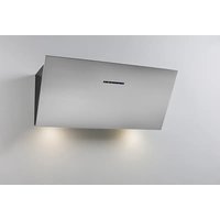
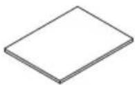
Download the instructions for your Basket in PDF format for free! Find your manual Split Easy Up - Airforce and take your electronic device back in hand. On this page are published all the documents necessary for the use of your device. Split Easy Up by Airforce.
USER MANUAL Split Easy Up Airforce
Gabrielle Split
| D | MONTAGE- UND GEBRAUCHSANWEISUNG |
| GB | INSTRUCTIONS ON MOUNTING AND USE |
| F | PRESCRIPTIONS DE MONTAGE ET MODE D'EMPLOI |
| NL | MONTAGEVOORSCHRIFTEN EN GEBRUIKSAANWIIZING |
| ES | MONTAJE Y MODO DE EMPLEO |
| I | ISTRUZIONI DI MONTAGGIO E D'USO |

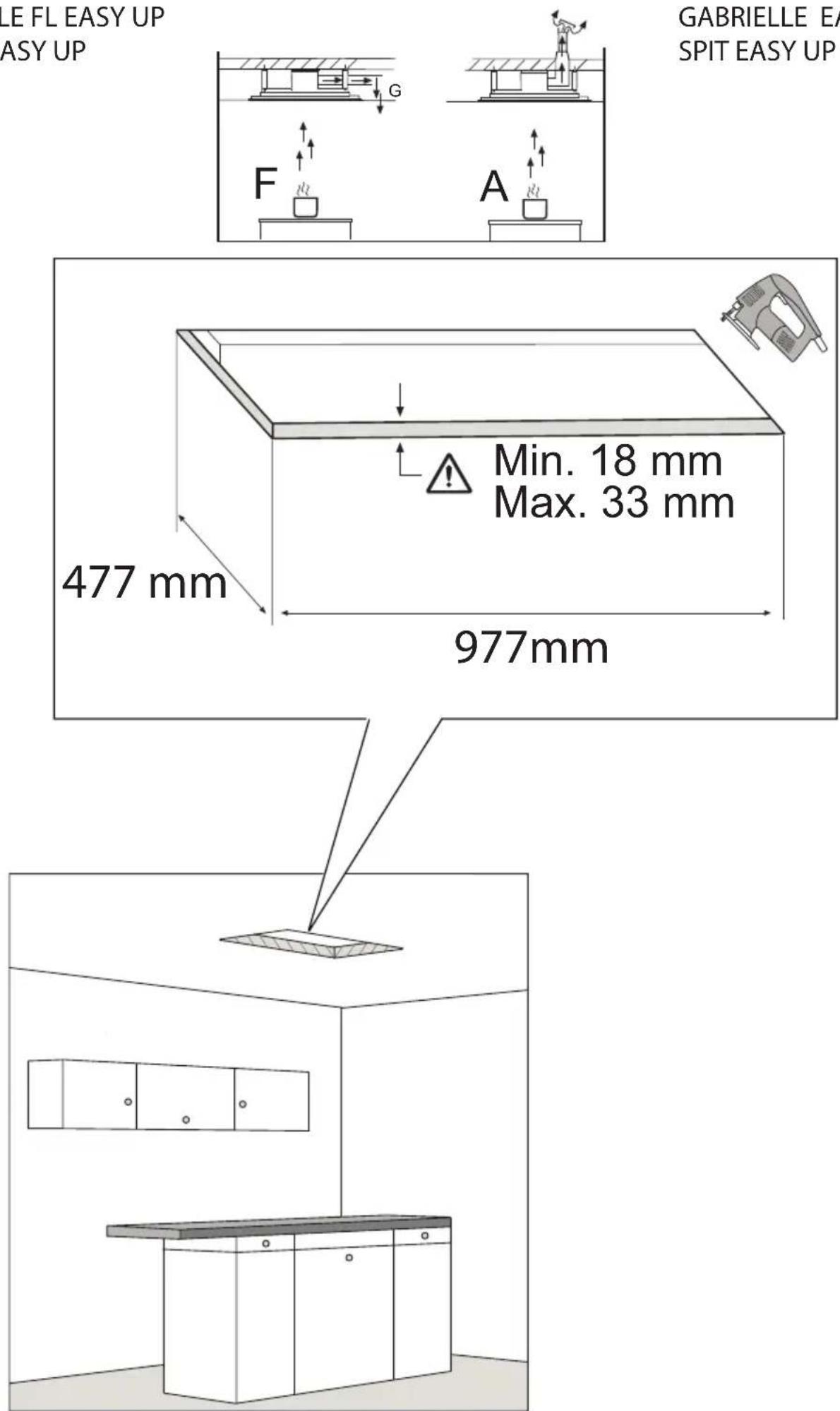
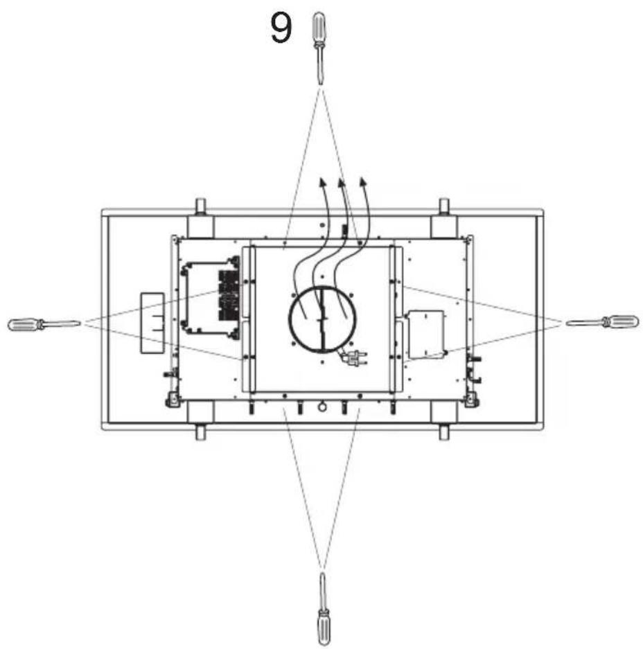
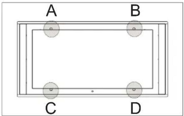
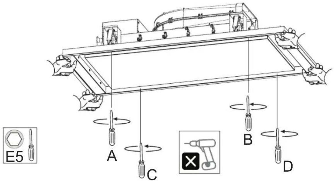
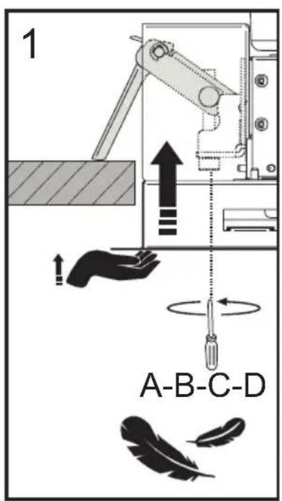
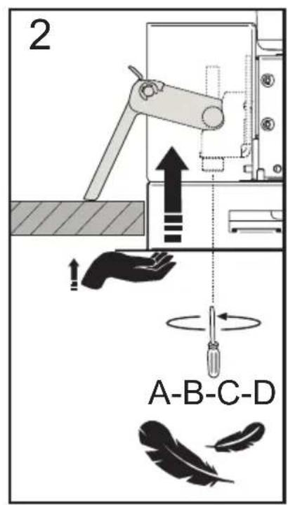
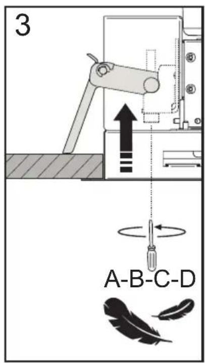
Checking the ceiling for first installation:
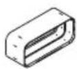
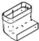
- The ceiling must be flat, horizontal and sufficiently solid and strong. - The hood is designed to be installed in a false ceiling. The false ceiling must be solid and have an adequate load capacity for a product weighing max. 30 kg.
Do not install the hood directly in the false ceiling panels, but use a suitable frame or support.
Installation of plasterboard panels:
Attention!: installation must be performed by qualified installers.
natural_image
Illustration of two gloves with textured soles (no text or symbols)IT Per tutte le operazioni di installazione e manutenzione utilizzare guanti da lavoro
EN Always wear work gloves for all installation and maintenance operations
DE Bei allen Installations- und Instandhaltungsarbeiten immer Schutzhandschuhe tragen.
FR Munissez-vous de gants de travail avant d'effectuer toute opération d'installation et d'entretien.
NL Draag bij alle installatie- en onderhoudswerkzaamheden werkhandschoenen.
ES Todas las operaciones de instalación y mantenimiento se deben realizar utilizando guantes de trabajo.
PT Para todas as operações de instalação e manutenção, utilize luvas adequadas para este tipo de atividade
GR Πάντοτε να φοράτε γάντια εργασίας για όλες τις επεμβάσεις εγκατάστασης και συντήρησης.
SV Använd alltid skyddshandskar vid installation och underhåll.
FI Käytä asennus- ja huoltotöissä suojakäsineitä.
NO Ved alle installasjonsprosedyrer og alt vedlikehold av ventilatoren må man bruke arbeidshansker
DA Ved alle installations- og vedligeholdelsesindgreb skal der bæres arbejdshandsker.
PL Wszelkie czynności montażowe i konserwacyjne wykonywać w rękawicach ochronnych.
CZ Při všech instalačních a údržbových pracích používejte pracovní rukavice
SK Pri všetkých inštalačných a údržbárskych prácach používajte ochranné pracovné rukavice.
HU Valamennyi üzembe helyezési és karbantartási müvelethez használjon védőkesztyűt
BG за всички операции по инсталиране и техническо обслужване използвайте работни ръкавици.
RO Pentru toate operațiile de instalare și întreținere utilizați mănuși de protecție.
RU Для выполнения всех операций по установке и уходу используйте рабочие перчатки.
ET Kasutage paigaldus- ja hooldustöödel kaitsekindaid,
Model:
GABRIELLE FL EASY UP
SPIT FL EASY UP
Model:
GABRIELLE EASY UP
SPIT EASY UP
Model:
GABRIELLE FL EASY UP
SPIT FL EASY UP
Model:
GABRIELLE FL EASY UP
SPIT FL EASY UP

Model:
GABRIELLE FL EASY UP
SPIT FL EASY UP
Model:
GABRIELLE FL EASY UP
SPIT FL EASY UP
Model:
GABRIELLE FL EASY UP
SPIT FL EASY UP
Model:
GABRIELLE FL EASY UP
SPIT FL EASY UP
Model:
GABRIELLE FL EASY UP
SPIT FL EASY UP
Model:
GABRIELLE FL EASY UP
SPIT FL EASY UP
Model:
GABRIELLE FL EASY UP
SPIT FL EASY UP
Model:
GABRIELLE FL EASY UP
SPIT FL EASY UP

natural_image
Isometric technical line drawing of a structural frame with internal components and directional arrows (no text or symbols)
natural_image
Technical line drawing of a mechanical assembly with mounting brackets and internal components (no text or symbols)
Model:
GABRIELLE EASY UP
SPIT EASY UP
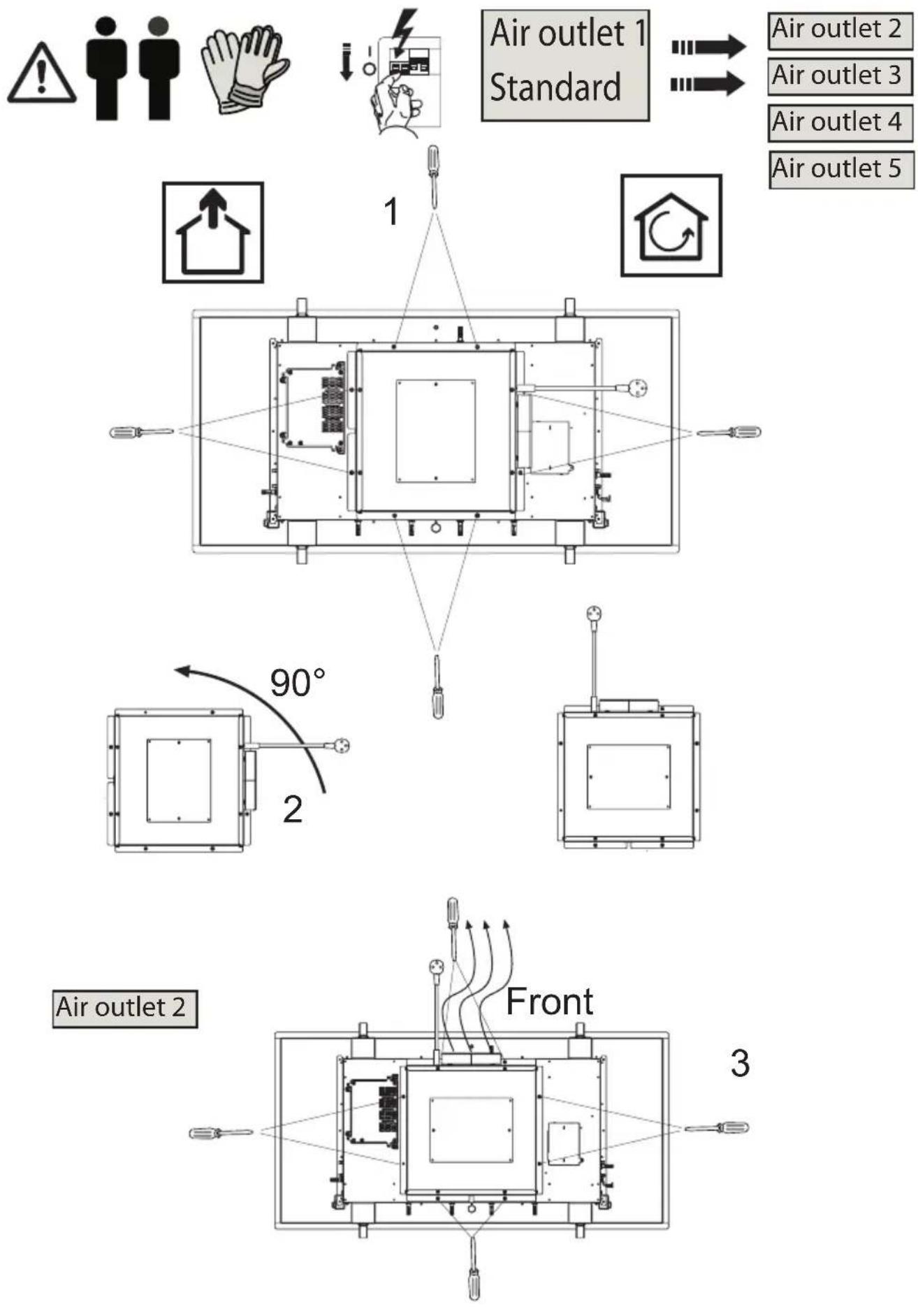
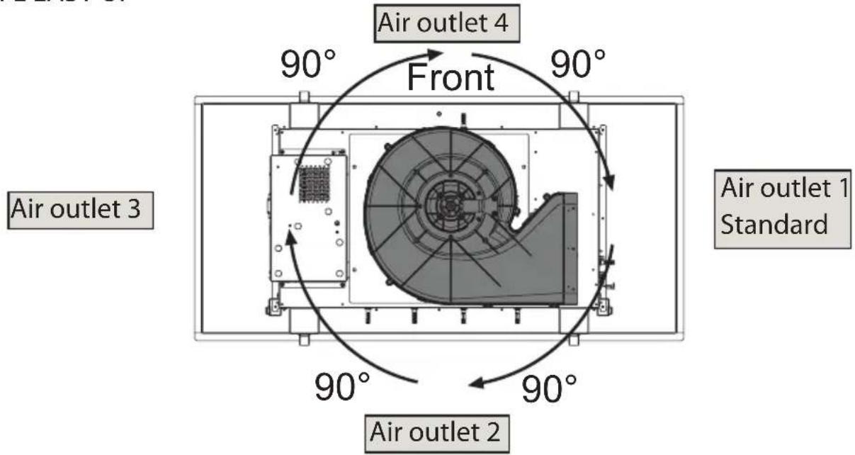
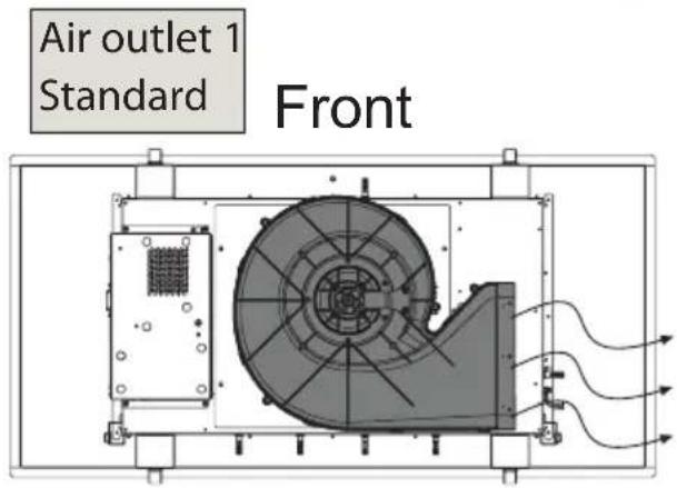
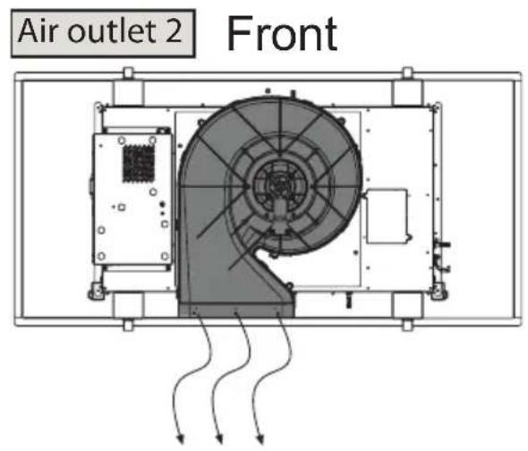
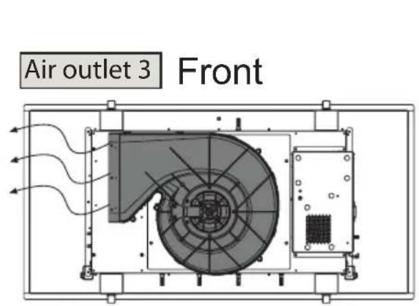
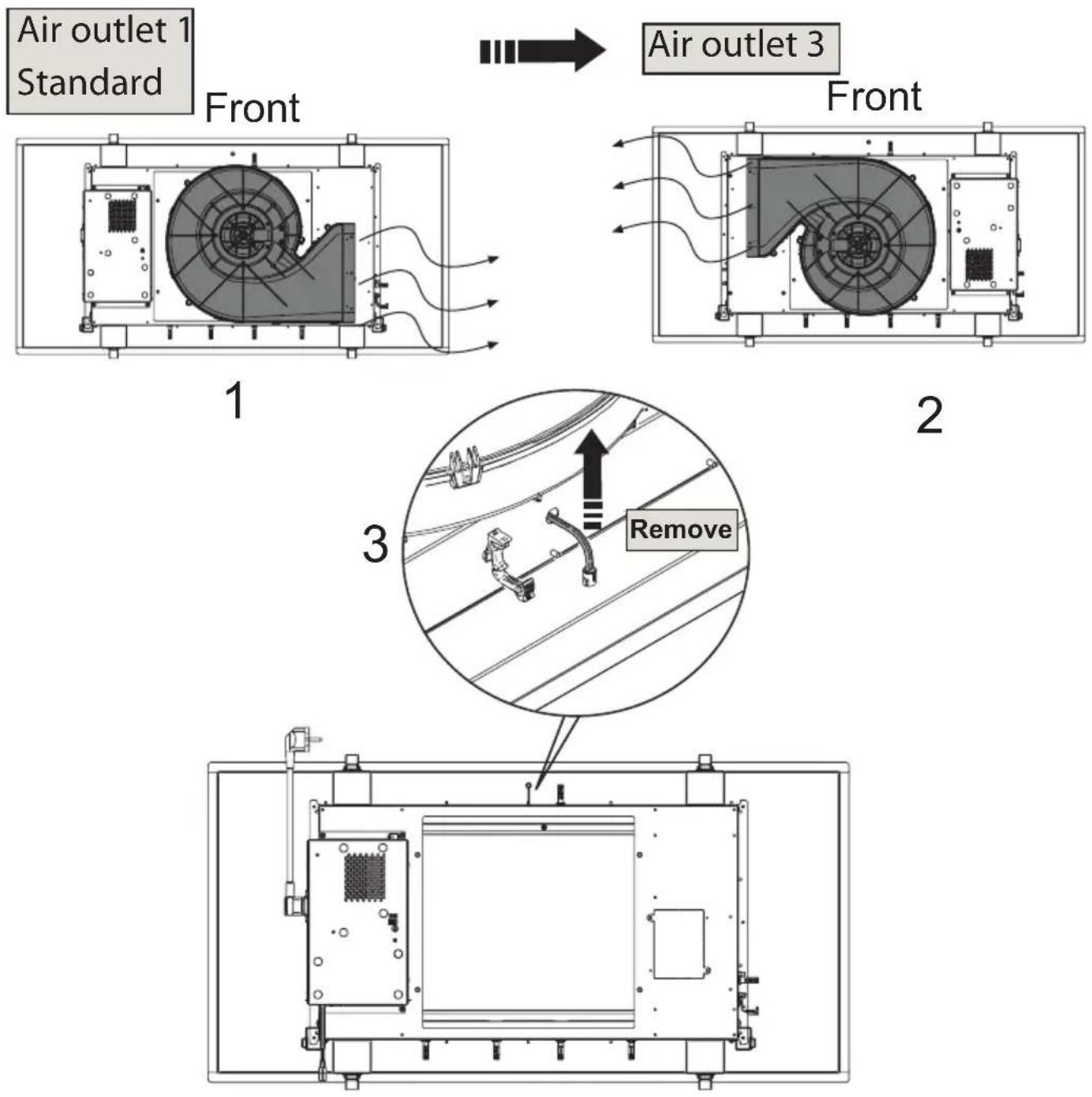
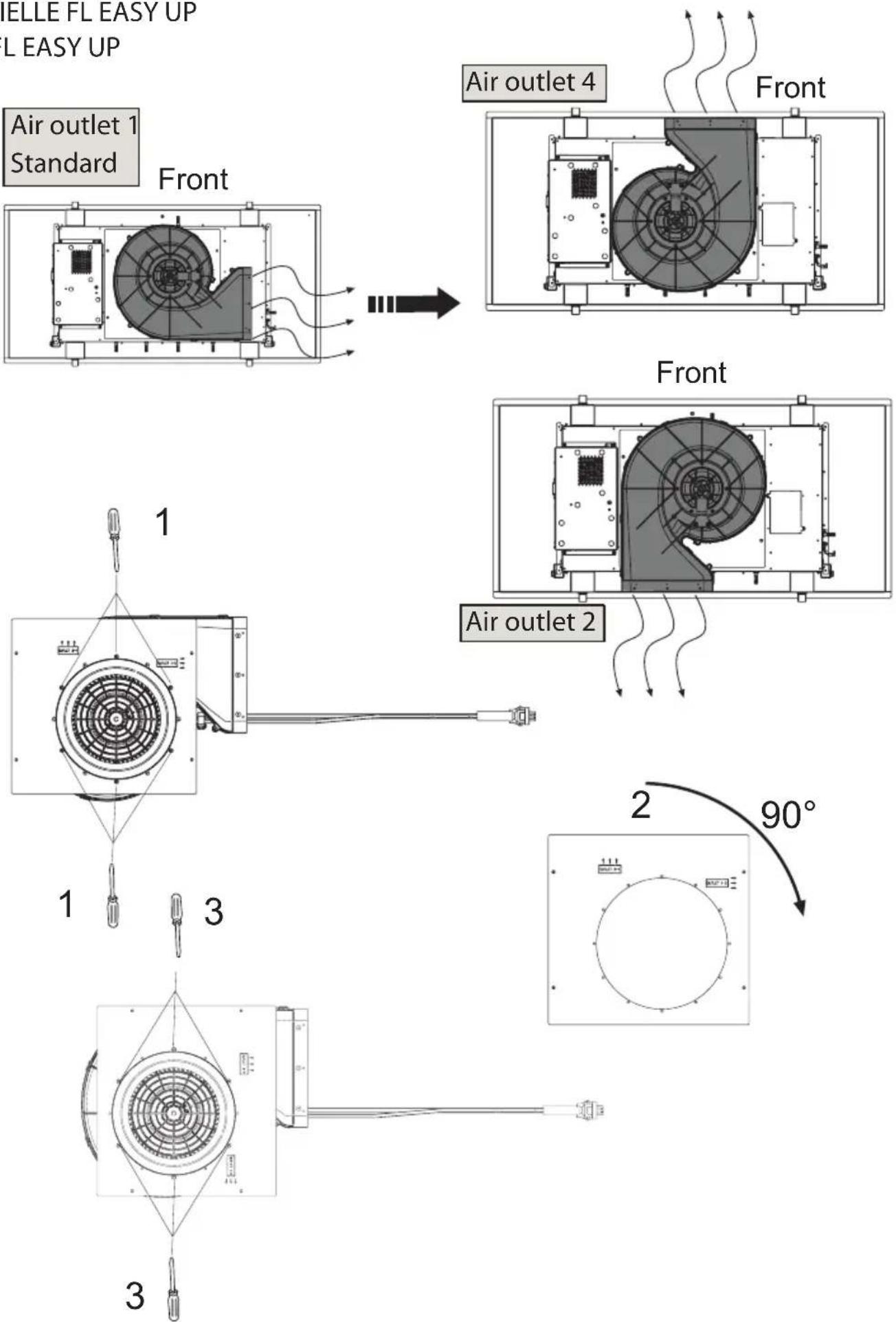
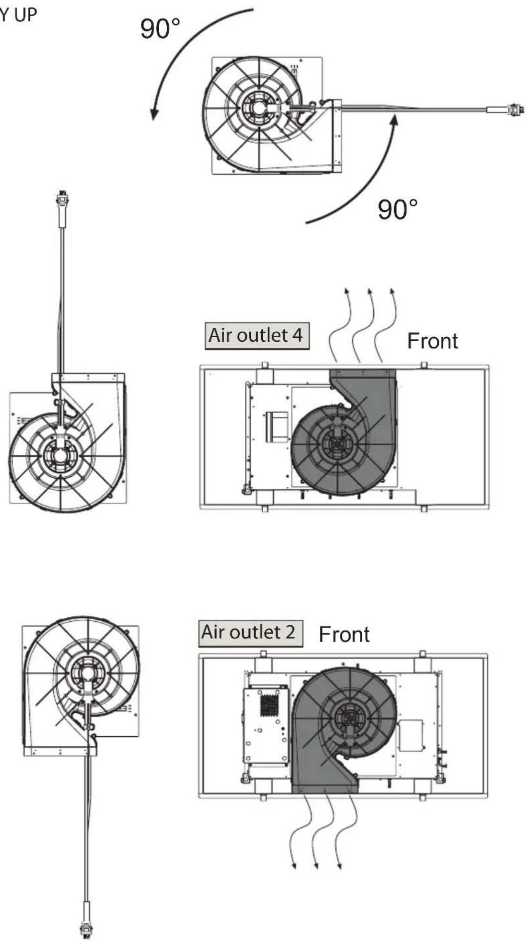
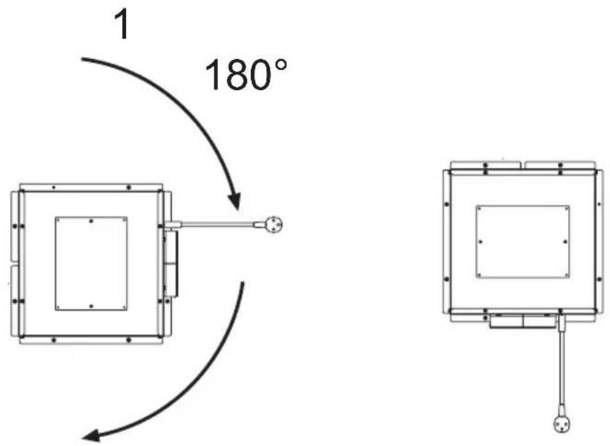
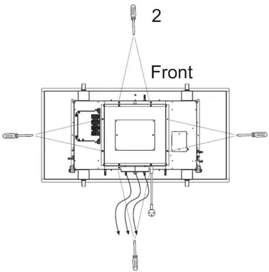
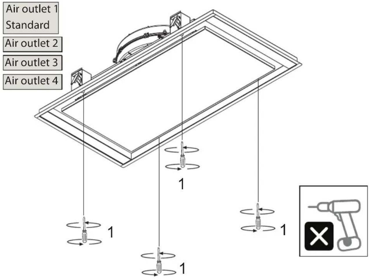
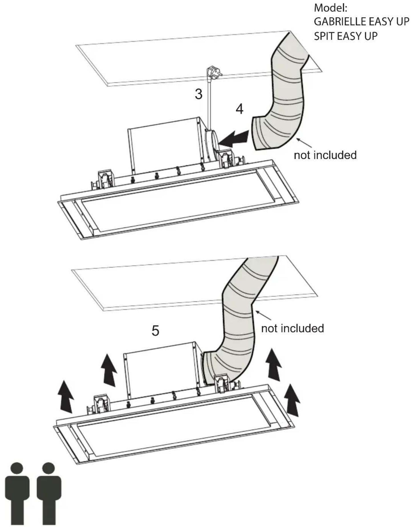
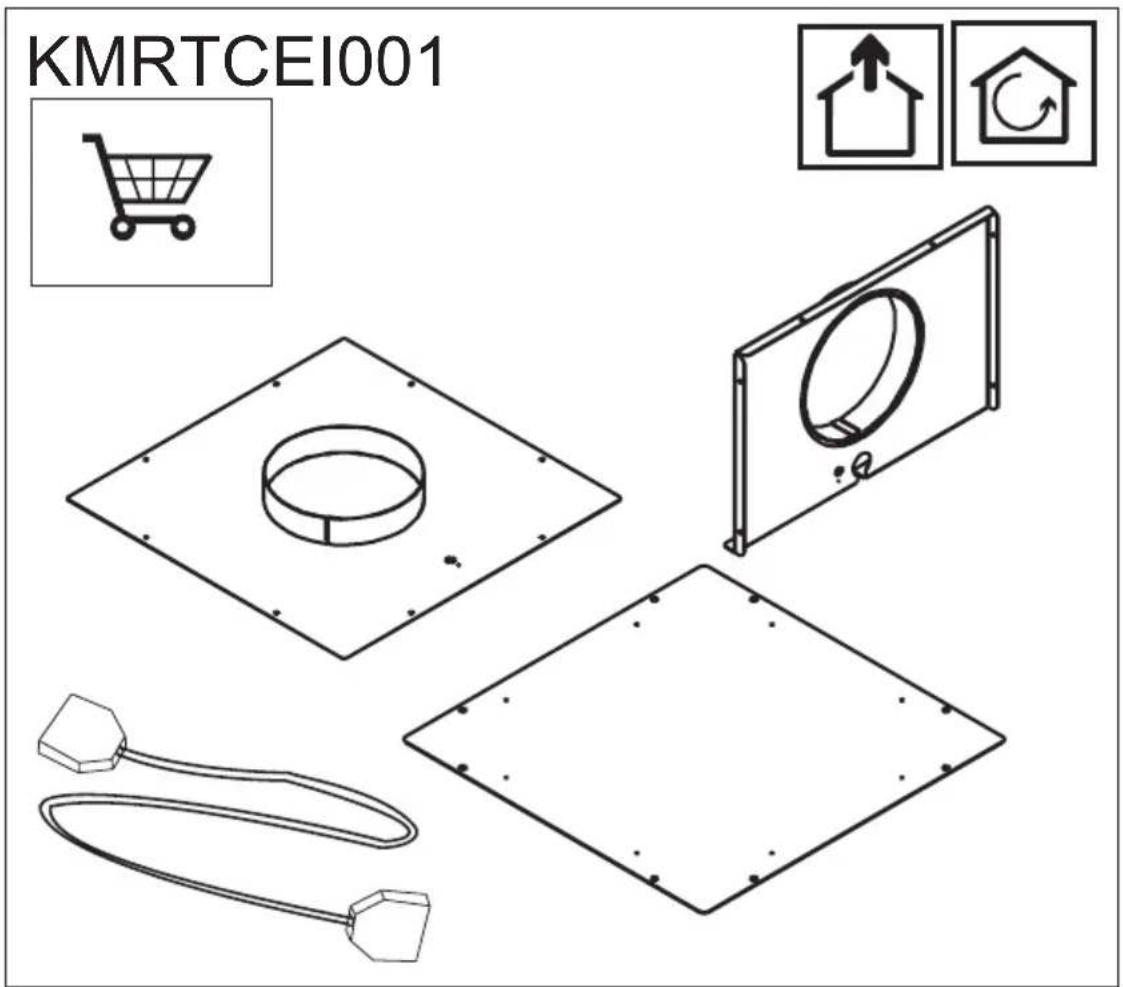
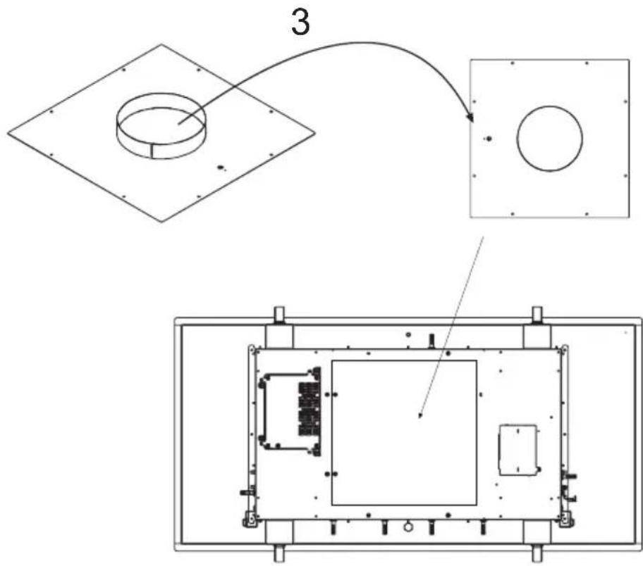
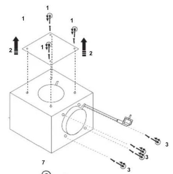
Air outlet 3
Model:
GABRIELLE EASY UP
SPIT EASY UP
Model:
GABRIELLE EASY UP
SPIT EASY UP
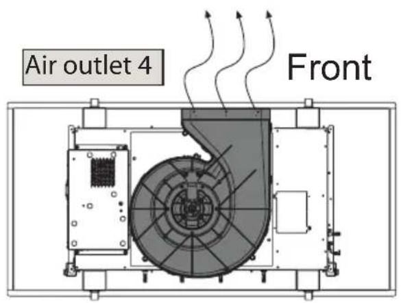
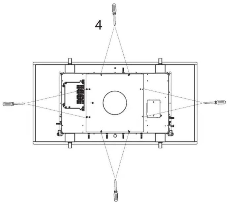
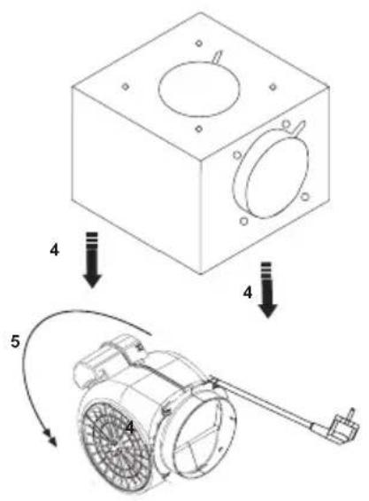
Air outlet 4

natural_image
Pure technical line drawing of a rectangular frame with internal components and a hanging hook (no text or symbols)
Model:
GABRIELLE EASY UP
SPIT EASY UP
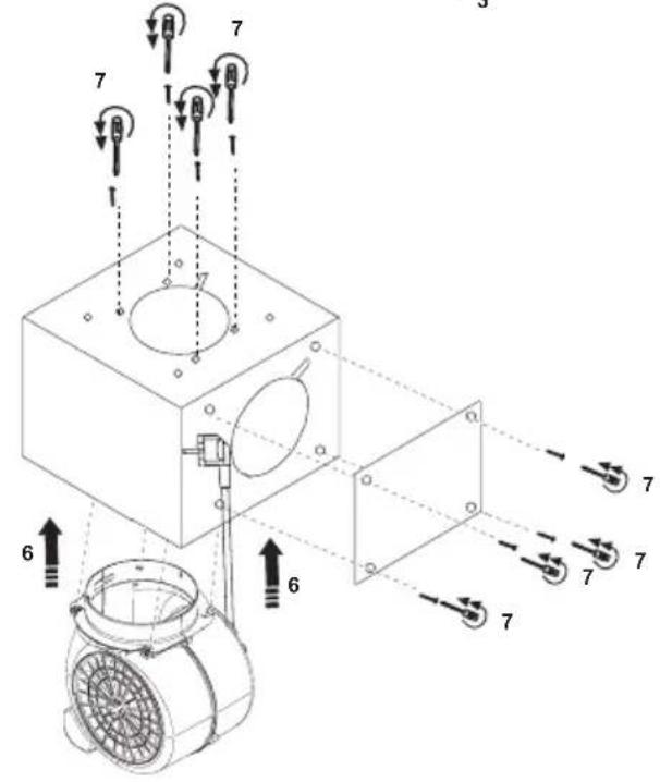
Air outlet 5
Model:
GABRIELLE EASY UP
SPIT EASY UP
Model:
GABRIELLE FL EASY UP
SPIT FL EASY UP
Model:
GABRIELLE EASY UP
SPIT EASY UP
Model:
GABRIELLE FL EASY UP
SPIT FL EASY UP

Model:
GABRIELLE FL EASY UP
SPIT FL EASY UP
Model:
GABRIELLE EASY UP
SPIT EASY UP
Model:
GABRIELLE FL EASY UP
SPIT FL EASY UP
Model:
GABRIELLE EASY UP
SPIT EASY UP
Model:
GABRIELLE FL EASY UP
SPIT FL EASY UP
Model:
GABRIELLE EASY UP
SPIT EASY UP
natural_image
Technical line drawing of a mechanical assembly with no visible text or symbols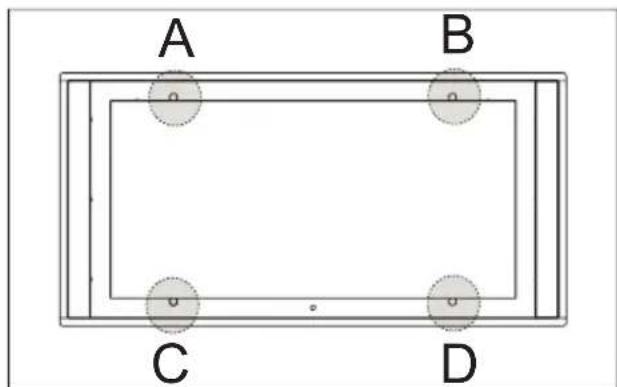
natural_image
Simple diagram showing a black arrow pointing upward from two circular shapes (no text or symbols)A-B-C-D
flowchart
graph TD
    A["1"] --> B["2"]
    B --> C["3"]
    C --> D["4"]
    D --> E["5"]
    E --> F["6"]
    F --> G["7"]
    G --> H["8"]
    H --> I["9"]
    I --> J["10"]
    J --> K["11"]
    K --> L["12"]
    style A fill:#f9f,stroke:#333
    style B fill:#ccf,stroke:#333
    style C fill:#cfc,stroke:#333
    style D fill:#fcc,stroke:#333
    style E fill:#cff,stroke:#333
    style F fill:#ffc,stroke:#333
    style G fill:#cfc,stroke:#333
    style H fill:#fcc,stroke:#333
    style I fill:#ffc,stroke:#333
    style J fill:#fcc,stroke:#333
    style K fill:#cfc,stroke:#333
    style L fill:#fcc,stroke:#333
flowchart
graph LR
    A["1"] --> B["1"]
    B --> C["1"]
    style A fill:#f9f,stroke:#333
    style B fill:#ccf,stroke:#333
    style C fill:#cfc,stroke:#333
    note1["Aktivkohlefilter\nCharcoal Filter\nFiltre à charbon\nKoolstofffilter\nFiltro al carbón\nFiltro al carbone"] -.-> A
flowchart
graph TD
    A["Feed Filter"] --> B["Anti-Grease Filter"]
    B --> C["Filtre antigraisse"]
    C --> D["Vetch Filter"]
    D --> E["Filtro antigrase"]
    E --> F["Filtro antigrasso"]
    style A fill:#f9f,stroke:#333
    style B fill:#ccf,stroke:#333
    style C fill:#cfc,stroke:#333
    style D fill:#fcc,stroke:#333
    style E fill:#cff,stroke:#333
    style F fill:#ffc,stroke:#333
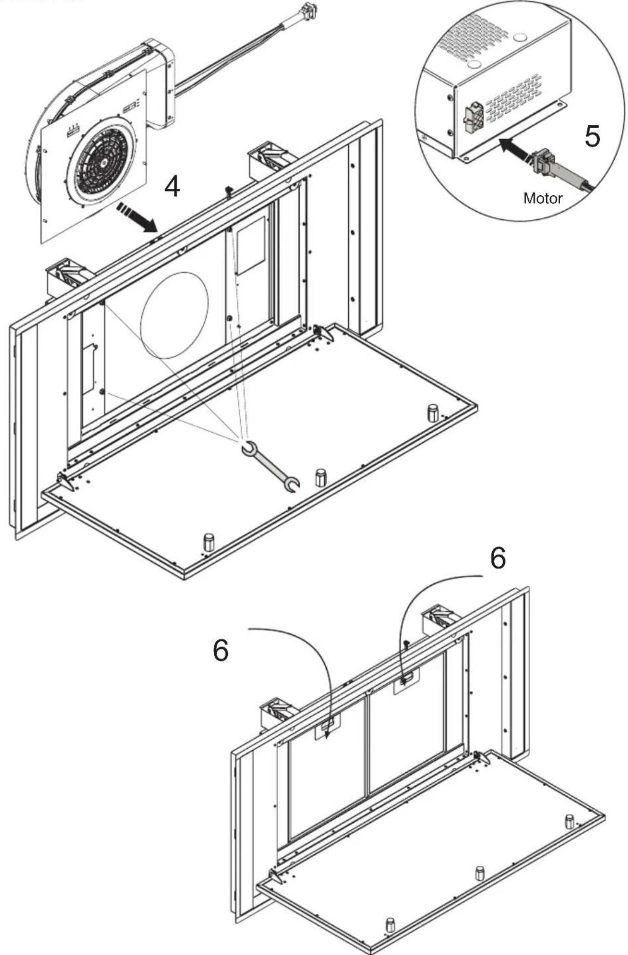
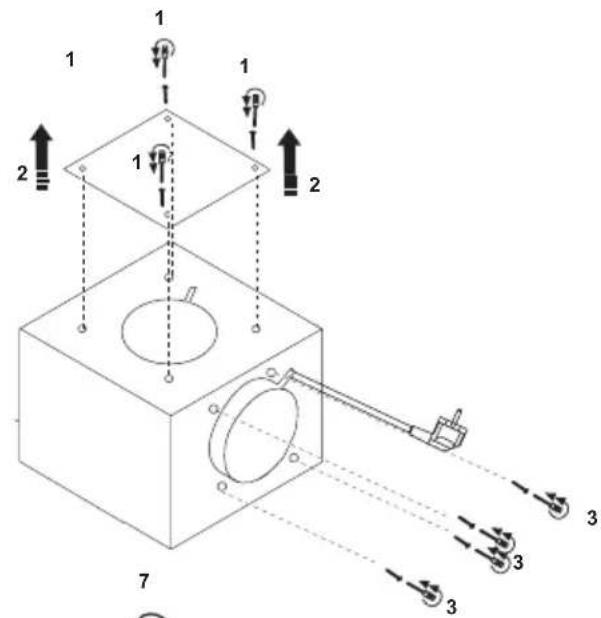
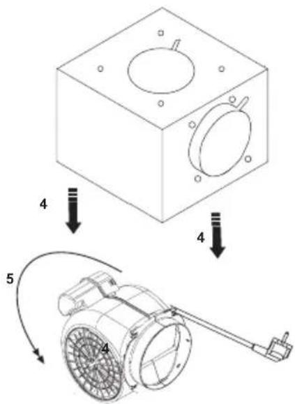
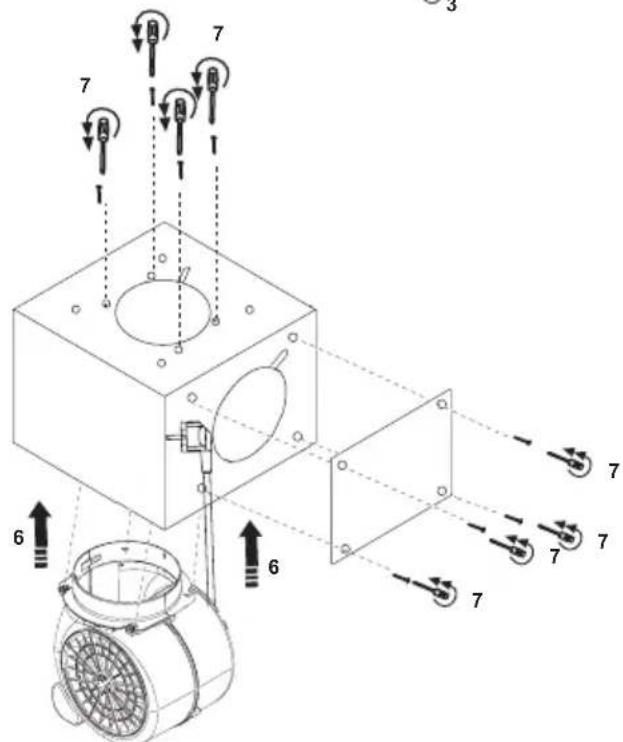
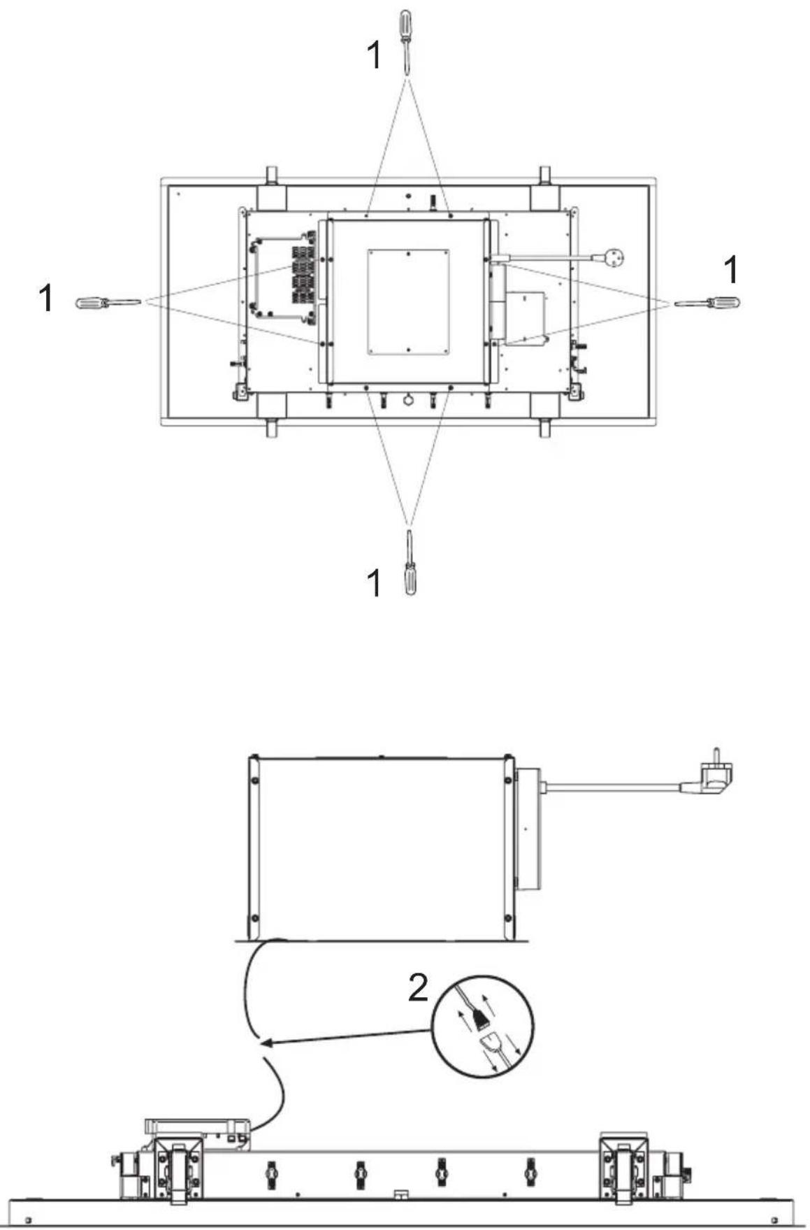
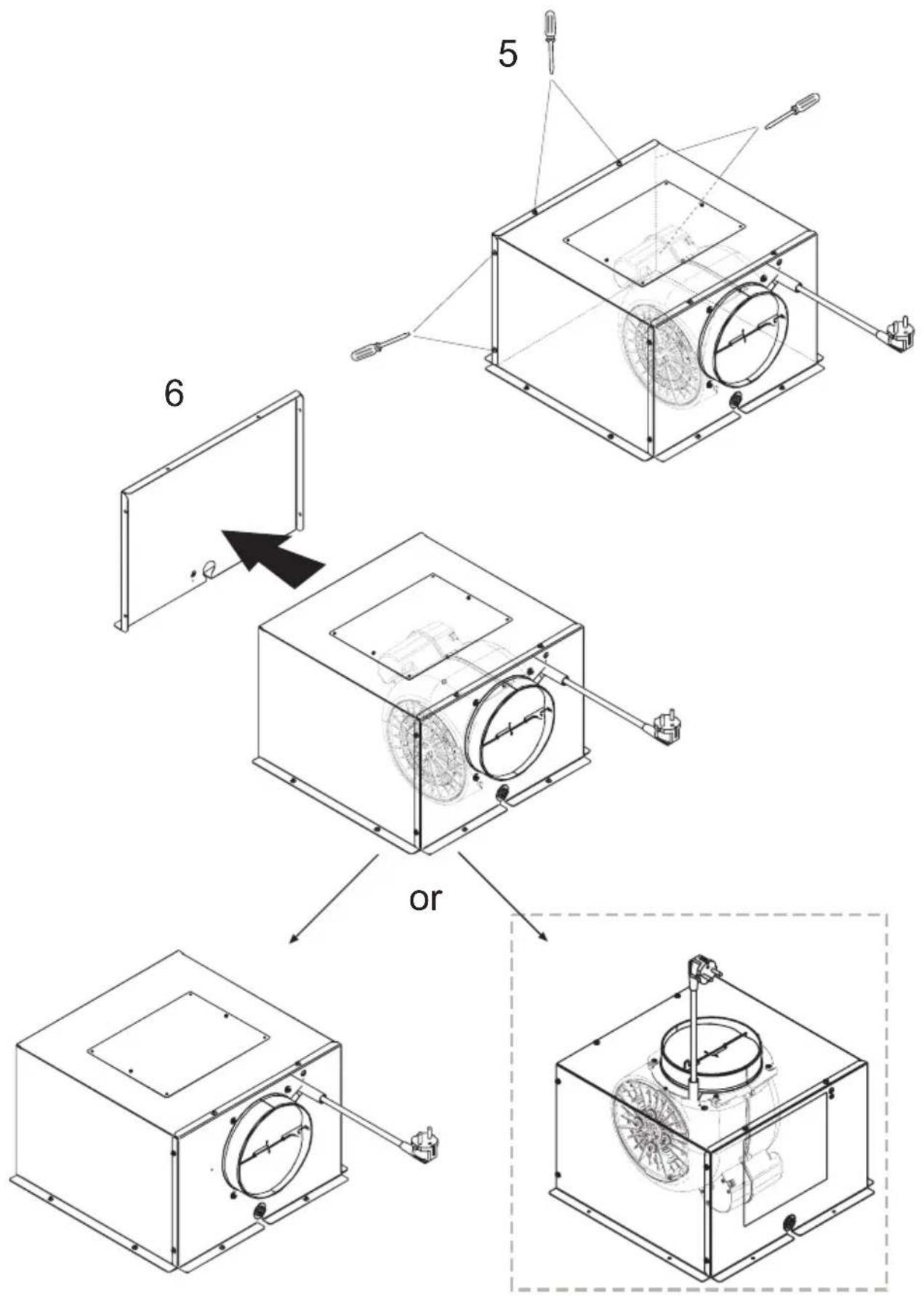
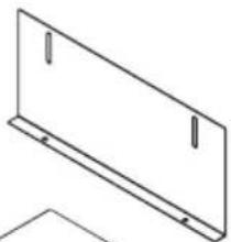
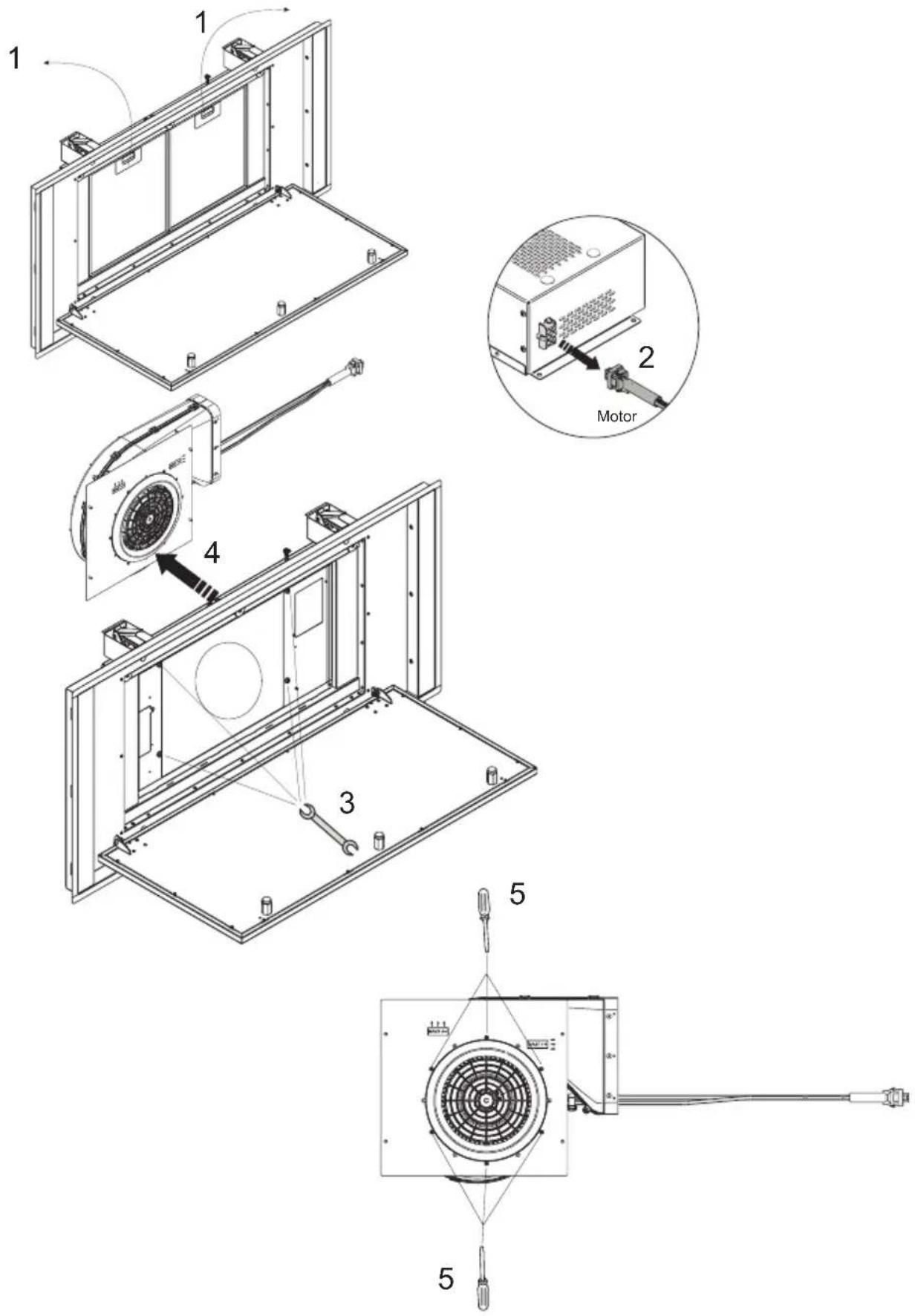
Installation with remote motor
Model:
GABRIELLE EASY UP
SPIT EASY UP
Model:
GABRIELLE EASY UP
SPIT EASY UP
Model:
GABRIELLE EASY UP
SPIT EASY UP
Model:
GABRIELLE EASY UP
SPIT EASY UP
Model:
GABRIELLE EASY UP
SPIT EASY UP
Model:
GABRIELLE EASY UP
SPIT EASY UP
natural_image
Simple line drawing of two connected geometric shapes with no text or symbols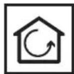
Model:
GABRIELLE FL EASY UP
SPIT FL EASY UP
Installation with remote motor
KMRBLJCEI001
natural_image
Simple line drawing of a shopping cart icon (no text or symbols)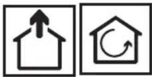
natural_image
Two simple line icons: a house with an upward arrow and a house with a circular arrow (no text or symbols)
natural_image
Isometric line drawing of a rectangular electronic device with a slot and mounting bracket (no text or symbols)
natural_image
Simple line drawing of a rectangular panel with two vertical lines on top (no text or symbols)
natural_image
Simple line drawing of a rectangular panel with two vertical slots and a base (no text or symbols)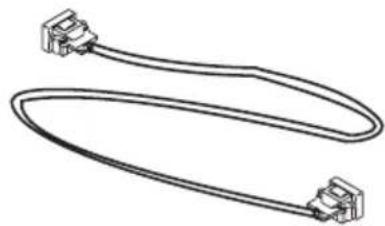
natural_image
Pure electrical circuit lines without any symbols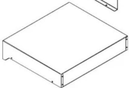
natural_image
Isometric line drawing of a rectangular metal frame with mounting holes (no text or symbols)Model:
GABRIELLE FL EASY UP
SPIT FL EASY UP
Model:
GABRIELLE FL EASY UP
SPIT FL EASY UP
Model:
GABRIELLE FL EASY UP
SPIT FL EASY UP
Model:
GABRIELLE FL EASY UP
SPIT FL EASY UP
Model:
GABRIELLE FL EASY UP
SPIT FL EASY UP
natural_image
Technical line drawing of a mechanical device with labeled components (no text or symbols present)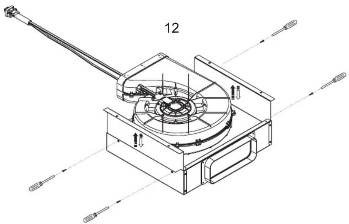
natural_image
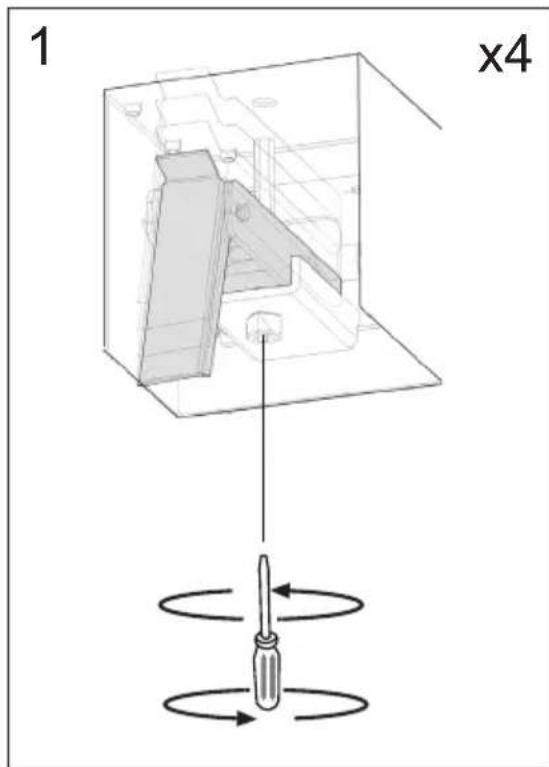
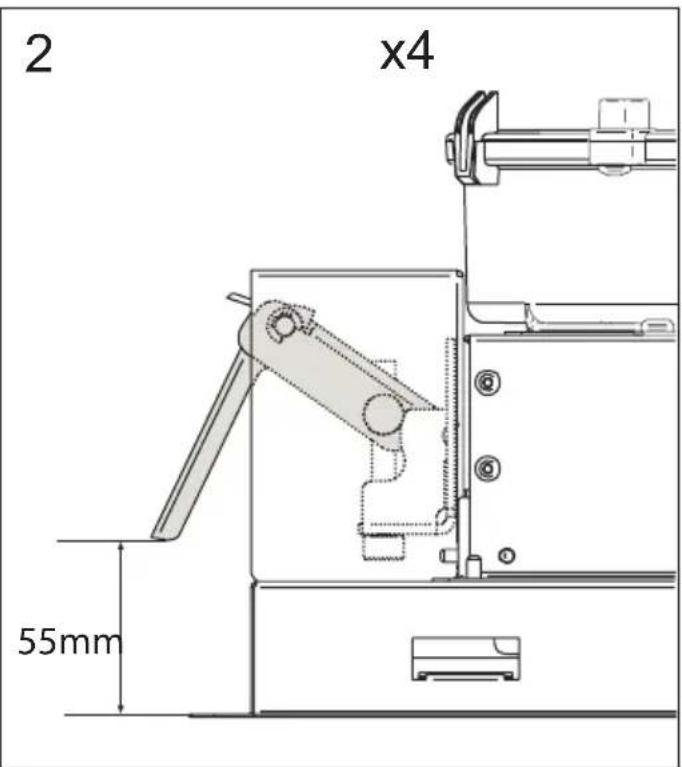
Technical line drawing of a mechanical device with labeled component '12' and directional arrows indicating assembly (no text or symbols beyond label)Model:
GABRIELLE FL EASY UP
SPIT FL EASY UP
flowchart
graph TD
    A["Truck Moving"] --> B["Shipping Mode"]
    C["Truck Recycling"] --> D["Shipping Mode"]
    E["Truck Transport"] --> F["Shipping Mode"]
    G["Truck Freight"] --> H["Shipping Mode"]
    I["Truck Waste"] --> J["Shipping Mode"]
    K["Truck Waste"] --> L["Shipping Mode"]
    M["Truck Waste"] --> N["Shipping Mode"]
    O["Truck Waste"] --> P["Shipping Mode"]
    Q["Truck Waste"] --> R["Shipping Mode"]
    S["Truck Waste"] --> T["Shipping Mode"]
    U["Truck Waste"] --> V["Shipping Mode"]
    W["Truck Waste"] --> X["Shipping Mode"]
    Y["Truck Waste"] --> Z["Shipping Mode"]
    AA["Truck Waste"] --> AB["Shipping Mode"]
    AC["Truck Waste"] --> AD["Shipping Mode"]
    AE["Truck Waste"] --> AF["Shipping Mode"]
    AG["Truck Waste"] --> AH["Shipping Mode"]
    AI["Truck Waste"] --> AJ["Shipping Mode"]
    AK["Truck Waste"] --> AL["Shipping Mode"]
    AM["Truck Waste"] --> AN["Shipping Mode"]
    AO["Truck Waste"] --> AP["Shipping Mode"]
    AQ["Truck Waste"] --> AR["Shipping Mode"]
    AS["Truck Waste"] --> AT["Shipping Mode"]
    AU["Truck Waste"] --> AV["Shipping Mode"]
    AW["Truck Waste"] --> AX["Shipping Mode"]
    AY["Truck Waste"] --> AZ["Shipping Mode"]
    BA["Truck Waste"] --> BB["Shipping Mode"]
    BC["Truck Waste"] --> BD["Shipping Mode"]
    BE["Truck Waste"] --> BF["Shipping Mode"]
    BG["Truck Waste"] --> BH["Shipping Mode"]
    BI["Truck Waste"] --> BJ["Shipping Mode"]
    BK["Truck Waste"] --> BL["Shipping Mode"]
    BM["Truck Waste"] --> BN["Shipping Mode"]
    BO["Truck Waste"] --> BP["Shipping Mode"]
    BZ["Truck Waste"] --> CA["Shipping Mode"]
    CB["Truck Waste"] --> CC["Shipping Mode"]
    CD["Truck Waste"] --> CE["Shipping Mode"]
    CF["Truck Waste"] --> CG["Shipping Mode"]
    CH["Truck Waste"] --> CI["Shipping Mode"]
    CJ["Truck Waste"] --> CK["Shipping Mode"]
    CL["Truck Waste"] --> CM["Shipping Mode"]
    CN["Truck Waste"] --> CX["Shipping Mode"]
    CY["Truck Waste"] --> CZ["Shipping Mode"]
    DA["Truck Waste"] --> DB["Shipping Mode"]
    DC["Truck Waste"] --> DE["Shipping Mode"]
    DF["Truck Waste"] --> DG["Shipping Mode"]
    DH["Truck Waste"] --> DI["Shipping Mode"]
    DJ["Truck Waste"] --> DK["Shipping Mode"]
    DL["Truck Waste"] --> DM["Shipping Mode"]
    DN["Truck Waste"] --> DE
    DG --> DE
    DX --> DX
    DB --> DX
    DB --> DX
    DB --> DX
    DB --> DX
    DB --> DX
    DB --> DX
    DB --> DX
    DB --> DX
    DB --> DX
    DB --> DX
    DB --> DX
    DB --> DX
    DB --> DX
    DB --> DX
    DB --> DX
    DB --> DX
    DB --> DX
    DB --> DX
    DB --> DX
    DB --> DX
    BB --> BB
    BB --> BB
    BB --> BB
    BB --> BB
    BB --> BB
    BB --> BB
    BB --> BB
    BB --> BB
    BB --> BB
    BB --> BB
    BB --> BB
    BB --> BB
    BB --> BB
    BB --> BB
    BB --> BB
    BB --> BB
    BB --> BB
    BB --> BB
    BB --> BB
    BB --> BB
    BB --> XX
    BB --> XX
    BB --> XX
    BB --> XX
    BB --> XX
    BB --> XX
    BB --> XX
    BB --> XX
    BB --> XX
    BB --> XX
    BB --> XX
    BB --> XX
    BB --> XX
    BB --> XX
    BB --> XX
    BB --> XX
Accessories
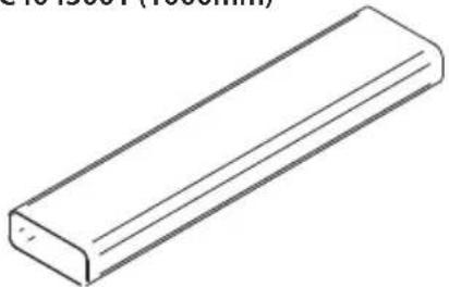
AFC4043001 (1000mm)
natural_image
Simple line drawing of a rectangular block (no text or symbols)AFC4043005
AFC4021003
AFCRAC0120994
AFC4043004 (90°)
AFC4043003 (90°)
AFC4043007 (15°)
AFC4043006 AFC4043002
KRASP003
AFCONFRACFP
AFCFCARFP
KRFH6
natural_image
Technical diagram of a mechanical assembly with no visible text or symbolsAFFCARFPH6
AFCFCAASPC78
Warnung
flowchart
graph TD
    T6 --> T1
    T1 --> fn
    fn --> T5
    T5 --> T3
    T3 --> T2
    T2 --> T4
    T4 --> T7
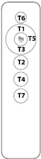
T1: +
T2 : On/Off motor
T3 : -
T4: On/Off light
T5:Tunable White e Dimmable light
fn: function
T6: Off general
T7:Timer
The appliance should not be used by children under 8 years of age and by persons with reduced physical, sensory and mental capabilities, or lack of experience and knowledge, unless they are supervised or have received instructions regarding the safe use of the appliance and are aware of the possible risks. Children must not play with the appliance. Any intended cleaning and maintenance by the user should not be carried out by children unless supervised. The hood should never be used without without the grid properly fitted! Never use the hood without the grill properly fitted!
The accessible components can overheat when the cooktop is in use.
The hood must not be connected to the flues of other appliances that run on gas or other fuels. When the hood is used at the same time as other appliances that run on gas or other fuels, provision must be made for an adequate supply of air. No food must be cooked flambé underneath the hood. The use of an unprotected flame could cause damage to the filters and could cause fires, so should be avoided. When frying food, never leave the pan unattended because the cooking oil could flare up. Please comply with the technical and safety provisions set forth by your local competent authorities regarding the ventilation of hoods.
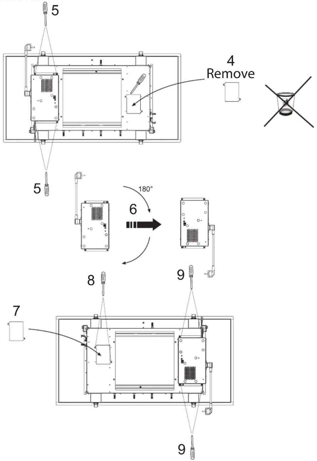
This appliance conforms to European Directive 2002/96/EC, Waste Electrical and Electronic Equipment (WEEE). Please dispose of this product correctly in the interest of health and the environment.
The symbol 📁 on the product, or on the documents accompanying the product, indicates that this appliance may not be treated as household waste. Instead it shall be handed over to the applicable collection point for the recycling of electrical and electronic equipment. Disposal must be carried out in accordance with local environmental regulations for waste disposal. For more detailed information about treatment, recovery and recycling of this product, please contact your local city office, your household waste disposal service or the shop where you purchased the product. If the power cable is damaged you should, in the interest of safety, contact the manufacturer or the manufacturer's technical assistance service to request a replacement, or ask someone who is similarly qualified.
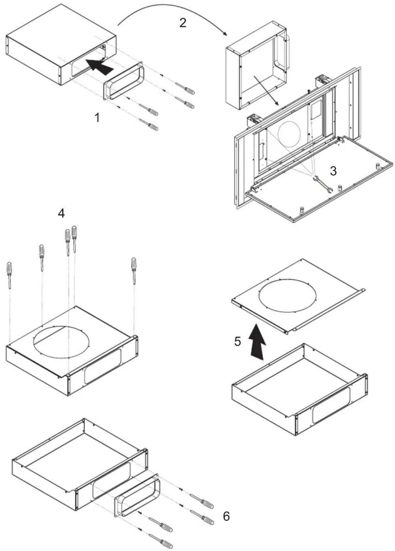
Check also the drawings on the initial pages with the alphabetical and numerical references in the explanatory text. Closely follow the instructions in this manual. We cannot accept liability for any faults, detriment or fire damage to the appliance due to non-compliance with the manual's instructions.
You should affix the hood to a wall of sufficient weight-bearing capacity, so not to one made of plasterboard.
The cooker hood must be placed at a minimum distance of 65 cm from the cooking plane for electric cookers and 65cm for gas or mixed cookers. If the instructions for installation for the gas hob specify a greater distance, this has to be taken into account. Do not tile, grout or silicone this appliance to the wall. Surface mounting only. Do not fix chimney flue to furniture or fly over shelves unless the chimney flue can be easily removed, in case maintenance is ever required.
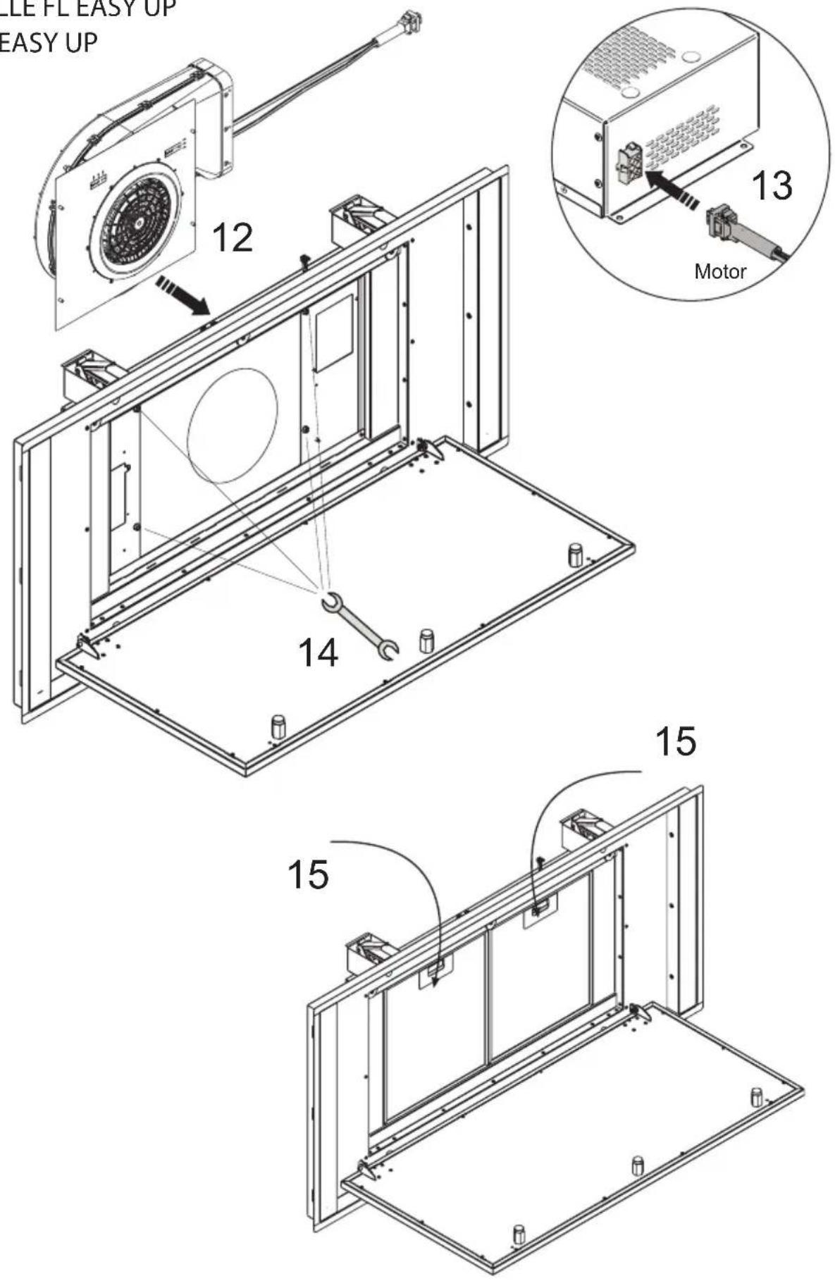
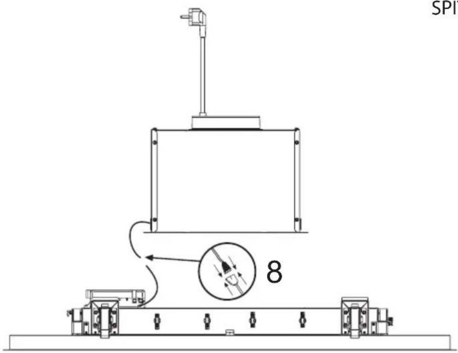
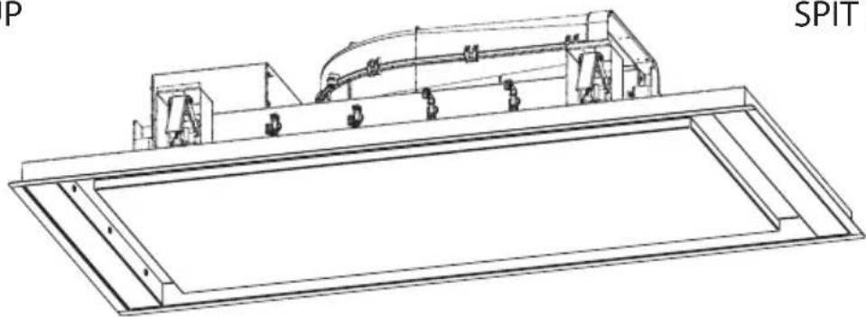
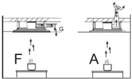
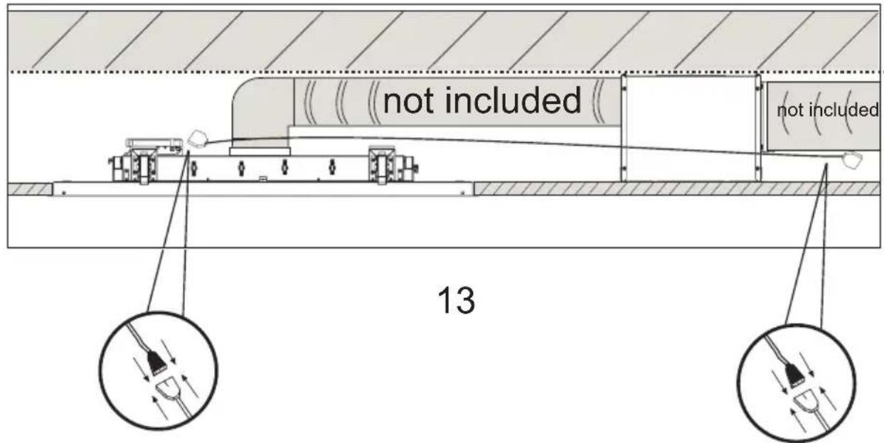
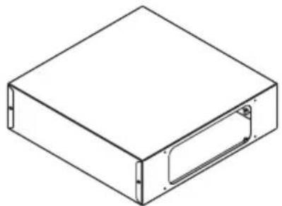
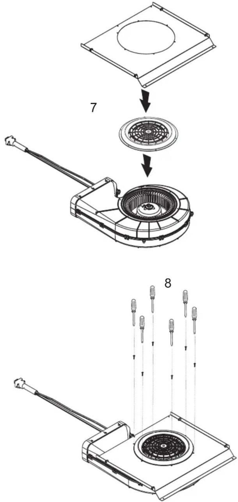
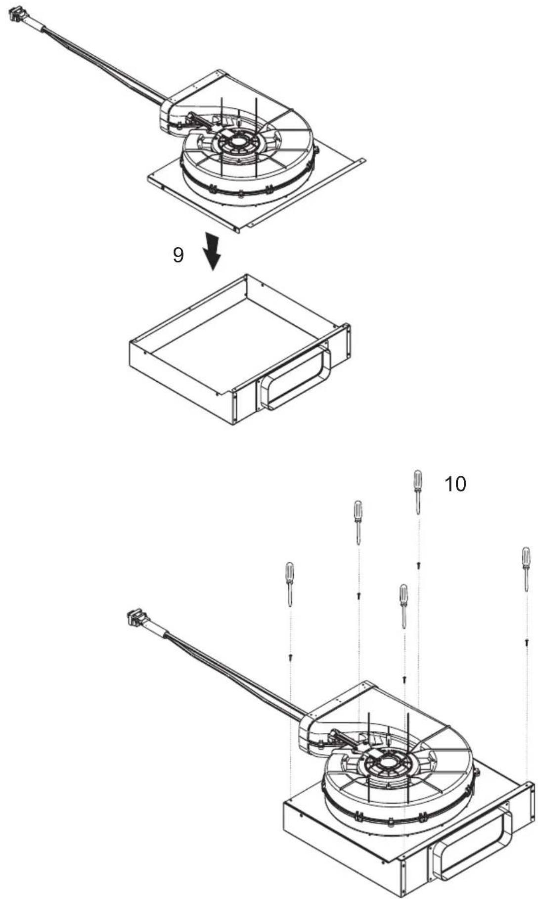
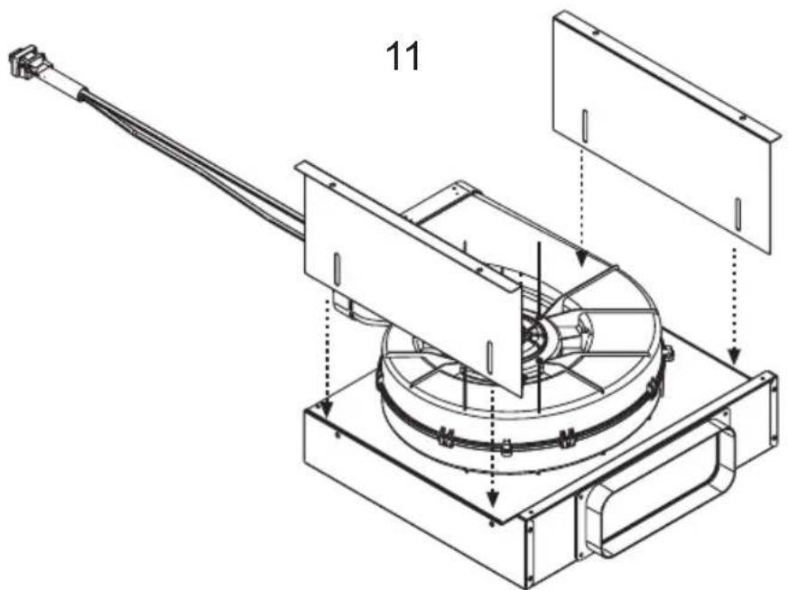
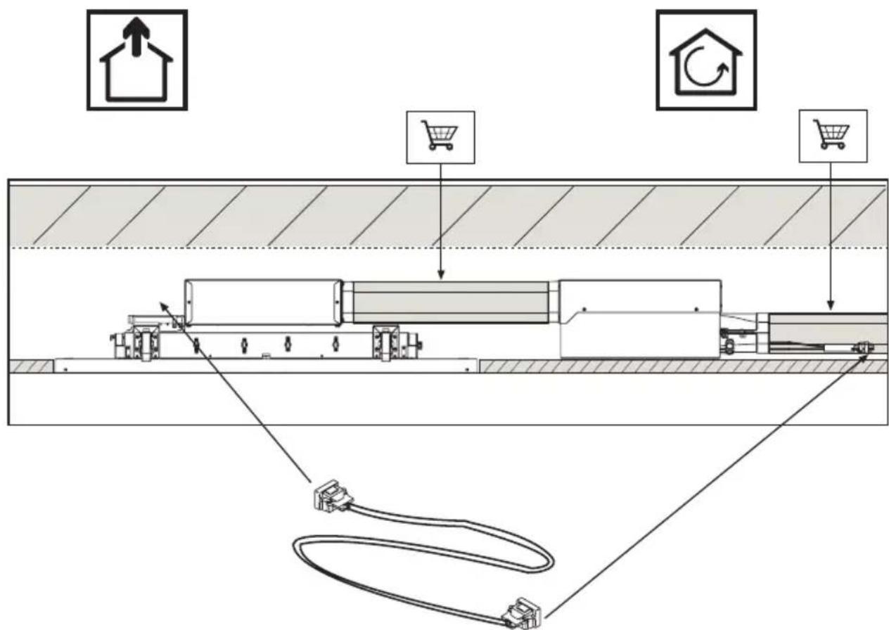
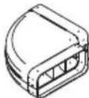
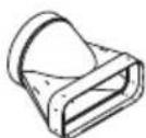
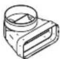
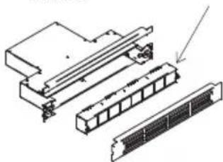
The cooker hood is provided with an upper air exit B for discharging fumes externally for models including chimney flue C (Suction Version A- exhaust pipe not supplied). If cooking fumes and vapours cannot be externally discharged, the cooker hood can be used in the recirculating version F: the installation of 1 active charcoal filter F allows the recirculation of fumes and vapours through the upper grid G.
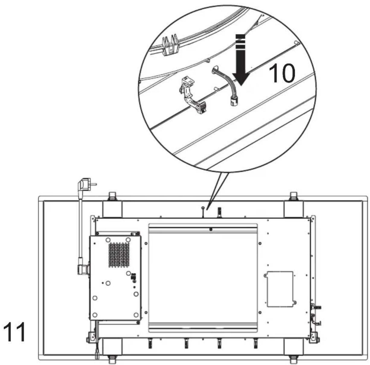
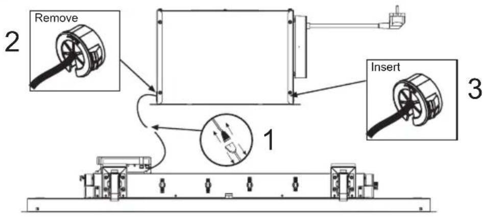
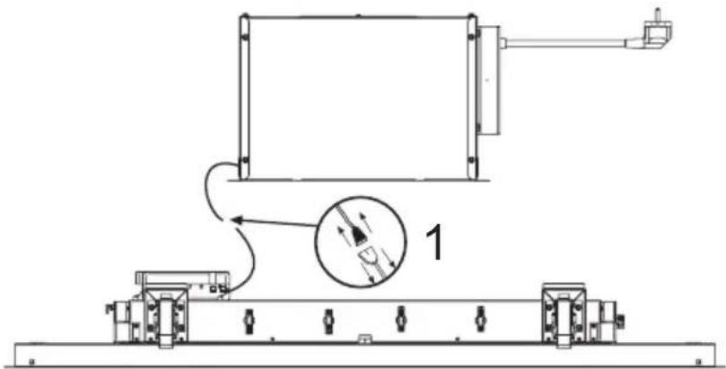
Make sure that there is a power socket near the hood and that the system has a 30 mA differential. The mains voltage must be the same as that on the label inside the hood. The hood has a 1250 mm power cable with or without plug: if it does have a plug, connect the hood to an accessible approved socket; or if it does not (connection direct to the mains), fit an approved bipolar switch with a minimum contact opening of no less than 3 mm (accessible). This installation and electrical connection must be executed by a qualified technician.
Product performance test carried out in accordance with standard (EU) No 65/2014-Ref: IEC 61591
Maximum performance is achieved by placing the mobile panels, if any, in the open position.
SPLIT
flowchart
graph TD
    T6 --> T1
    T1 --> fn
    fn --> T5
    T5 --> T3
    T3 --> T2
    T2 --> T4
    T4 --> T7
T1: +
T2 : On/Off motor
T3 : -
T4: On/Off light
T5:Tunable White e Dimmable light
fn: function
T6: Off general
T7:Timer
Notes: this remote control is universal but not all features are available on all models.
ON FIRST USE OR IN THE EVENT OF NEEDING TO CHANGE THE REMOTE CONTROL OR THE PRODUCT'S ELECTRONIC COMPONENTS, THE PAIRING PROCEDURE BETWEEN REMOTE CONTROL AND HOOD MUST BE PERFORMED (Valid for all models):
-
Power off the hood for at least 10 seconds
-
Power on the hood again
-
Within the first 5 sec press the lights button T4 and release after the lights have turned on
-
Within the next 5 sec press the motor button T2 and release it when the lights turn off
Now you need to wait approximately 10 seconds, after which you may use the hood normally.
SHOULD THERE BE ANY MALFUNCTIONS DUE TO INTERFERENCES WITH OTHER REMOTE CONTROLS NEARBY, PERFORM THE PROCEDURE TO CHANGE THE REMOTE CONTROL'S TRANSMISSION CODE (Valid for all models)
The remote control is supplied with default codes. Should you wish to generate new random codes, the following procedure must be performed: press simultaneously the two buttons plus T1 and minus T3 for at least 10 seconds. After the remote control's code has been changed, the pairing procedure must be performed.
Button T2 (On/Off motor): pressing the T2 button turns the motor on or off, acting on the T1(+) or T3 (-) buttons increases or decreases the speed
1° Speed: Green LED
2° Speed: Flashing green LED
3° Speed: Orange LED
4° Speed: Flashing orange LED
5° Speed: Red LED
6° Speed: flashing red LED (intensive timed for 8 minutes, after which it returns to 5 speed)
Button T4 :On/Off light (LED bar).
Light panel: when the fn and T4 keys are simultaneously pressed, panel light is On/Off Only for models with the Tunable White and Dimmable light feature
Press the button T5 to enter the Dimmable light function LED flashes green quickly (changing light intensity with the +/- buttons).
Press the button T5 again to enter the Tunable White function LED flashes orange quickly (changing light colour with the +/- buttons).
Press T5 again to exit the menu
N.B. In any case, after 10 sec of inactivity the remote control automatically exits the menu.
Button T6 (Off general): if the button is pressed for a long time, both the lights and the motor turn off.
Button T7 (timer) : with the motor running, pressing the T7 button activates the timer function lasting 5 minutes, indicated by the LED flashing red-green at the end of 5 minutes the motor switches off.
GABRIELLE
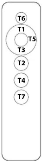
T1:+
T2 : On/Off motor
T3 : -
T4: On/Off light
T5:Tunable White e Dimmable light
T6: Off general
T7:Timer
Notes: this remote control is universal but not all features are available on all models.
ON FIRST USE OR IN THE EVENT OF NEEDING TO CHANGE THE REMOTE CONTROL OR THE PRODUCT'S ELECTRONIC COMPONENTS, THE PAIRING PROCEDURE BETWEEN REMOTE CONTROL AND HOOD MUST BE PERFORMED (Valid for all models):
- Power off the hood for at least 10 seconds
- Power on the hood again
- Within the first 5 sec press the lights button T4 and release after the lights have turned on
- Within the next 5 sec press the motor button T2 and release it when the lights turn off
Now you need to wait approximately 10 seconds, after which you may use the hood normally.
SHOULD THERE BE ANY MALFUNCTIONS DUE TO INTERFERENCES WITH OTHER REMOTE CONTROLS NEARBY, PERFORM THE PROCEDURE TO CHANGE THE REMOTE CONTROL'S TRANSMISSION CODE (Valid for all models)
The remote control is supplied with default codes. Should you wish to generate new random codes, the following procedure must be performed: press simultaneously the two buttons plus T1 and minus T3 for at least 10 seconds. After the remote control's code has been changed, the pairing procedure must be performed.
Button T2 (On/Off motor): pressing the T2 button turns the motor on or off, acting on the T1(+) or T3 (-) buttons increases or decreases the speed
1° Speed: Green LED
2° Speed: Flashing green LED
3° Speed: Orange LED
4° Speed: Flashing orange LED
5° Speed: Red LED
6° Speed: flashing red LED (intensive timed for 8 minutes, after which it returns to 5 speed)
Button T4: On/Off light
Only for models with the Tunable White and Dimmable light feature
Press the button T5 to enter the Dimmable light function LED flashes green quickly (changing light intensity with the +/- buttons).
Press the button T5 again to enter the Tunable White function LED flashes orange quickly (changing light colour with the +/- buttons).
Press T5 again to exit the menu
N.B. In any case, after 10 sec of inactivity the remote control automatically exits the menu.
Button T6 (Off general): if the button is pressed for a long time, both the lights and the motor turn off.
Button T7 (timer) : with the motor running, pressing the T7 button activates the timer function lasting 5 minutes, indicated by the LED flashing red-green at the end of 5 minutes the motor switches off.
Mainhitenance
Prior to any maintenance operation ensure that the cooker hood is disconnected from the electrical outlet.
Cleaning
The hood must be cleaned frequently both inside (apart from the area behind the grease filter) and outside. Use a cloth moistened with denatured alcohol or neutral liquid detergents. Never use products containing abrasives.
Warning
Failure to carry out the basic standards of the cleaning of the cooker hood and replacement of the filters may cause fire risks. Therefore we recommend observing these instructions.
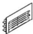
Anti-grease Filter
must be cleaned once a month, with non abrasive detergents, by hand or in dishwasher on low temperature and short cycle. When washed in a dishwasher, the grease filter may discolour slightly, but this does not affect its filtering capacity.
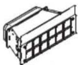
Charcoal Filter - (only for filter version)
The active charcoal filters F are not washable nor regenerative. It should be changed every 6 months in normal use. The active charcoal filters capture unpleasant cooking odours.
Led Light
If the lighting group LED does not work, please contact the technical service center in order to replace the whole group.
Reducing environmental impact:
To reduce energy consumption, we recommend you always use the lowest suction speed among those suitable for the cooking mode currently active, avoid leaving the appliance running for more than 15 minutes after burner shutdown and switch off the lights if you leave the cooking area.
Attention
T1: +
T2 : On/Off motor
T3 : -
T4: On/Off light
T5:Tunable White e Dimmable light
fn: function
T6: Off general
T7:Timer
flowchart
graph TD
    T6 --> T1
    T1 --> fn
    fn --> T5
    T5 --> T3
    T3 --> T2
    T2 --> T4
    T4 --> T7
T1: +
T2 : On/Off motor
T3 : -
T4: On/Off light
T5:Tunable White e Dimmable light
fn: function
T6: Off general
T7:Timer
Toets T4: On/Off licht (LED-balk).
T1: +
T2 : On/Off motor
T3 : -
T4: On/Off light
T5:Tunable White e Dimmable light
fn: function
T6: Off general
T7:Timer
flowchart
graph TD
    T6 --> T1
    T1 --> fn
    fn --> T5
    T5 --> T3
    T3 --> T2
    T2 --> T4
    T4 --> T7
T1: +
T2 : On/Off motor
T3 : -
T4: On/Off light
T5:Tunable White e Dimmable light
fn: function
T6: Off general
T7:Timer