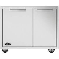
CAD130E - Barbecue DCS - Free user manual and instructions
Find the device manual for free CAD130E DCS in PDF.


User questions about CAD130E DCS
0 question about this device. Answer the ones you know or ask your own.
Ask a new question about this device
Download the instructions for your Barbecue in PDF format for free! Find your manual CAD130E - DCS and take your electronic device back in hand. On this page are published all the documents necessary for the use of your device. CAD130E by DCS.
USER MANUAL CAD130E DCS
INSTALLATION INSTRUCTIONS AND USER GUIDE
INSTRUCTIONS D'INSTALLATION ET GUIDE D'UTILISATION
Professional grill cart
text_image
DCS by Fisher&PaykelCONTENTS
Safety and warnings 3
Model identification & dimensions 4
Installation
Shipping inspection 5
Locating the cart 6
Cart assembly instructions 6-11
Attaching Side Shelf (optional) 112
Attaching Sink Drain Kit (optional) 13-17
Using the cart
Removing Drawers 18
Re-installing Drawers 18-19
Freezer Pack (optional) 18
Care & maintenance 20
Service 21
Thank you for selecting this DCS by Fisher & Paykel Grill Cart. This installation and user guide contains valuable information on how to properly install, and maintain your new Professional Grill Cart for years of safe and enjoyable use.
Please fill out and submit your Product Registration by visiting our website at www.dcsappliances.com and selecting “Support” on the home page and then selecting “Product Registration”. In addition, keep this guide handy, as it will help answer questions that may arise as you use your new Grill Cart.
For your convenience, product questions can be answered by a DCS Customer Care Representative at www.dcsappliances.com, or email: customer.care@fisherpaykel.com.
Note: please write the model, code, and serial numbers on this page for references (can be found on the inside, left wall of the tank drawer).
MODEL NUMBER CODE SERIAL NUMBER
IMPORTANT!
DO NOT discard any packing material (box, pallet, straps) until the unit has been inspected. Inspect the product to verify that there is no shipping damage. If any damage is detected, call the shipper and initiate a damage claim. DCS by Fisher & Paykel is not responsible for shipping damage.
To reduce the risk of fire, electrical shock, injury to persons, or damage when using the appliance, follow the important safety instructions listed below:
| ⚠WARNING! | |
 | Explosion HazardDo not store or use gasoline or other flammable vapors and liquids inside or in the vicinity of this or any other appliance.An LP cylinder not connected for use shall not be stored inside or in the vicinity of this unit. |
WARNING!


WARNING!
Tip Hazard
Do not push down on the top of the drawers. The unit could tip forward.
Do not overload drawers. Maximum rating of each drawer is 35 pounds.
Failure to follow this advice may result in injury.
IMPORTANT SAFETY INSTRUCTIONS!
- Do not allow children or pets to play in or around the cart.
- To prevent personal injury or damage to the drawers, do not overload them. The maximum rating of each drawer is 35 pounds.
- Do not store items of interest to children above or on the inside of any cart. Children could be seriously injured if they should climb onto or into the cart to reach these items.
- To prevent injury from tipping, all Series 9 grills must only be used with either CAD1-36E or CAD1-48E model carts.
IF YOU SMELL GAS:
- Do not turn on any electrical switch; do not use any phone in your building.
- Immediately call your gas supplier from a neighbor's phone.
- Follow the gas supplier's instructions.
- If you cannot reach your gas supplier, call the fire department.
- Installation and service must be performed by a qualified installer, service agency or the gas supplier.
text_image
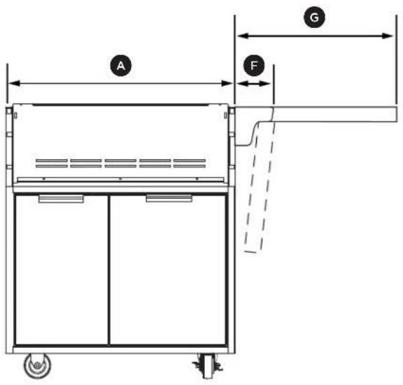
A G FCAD1-30 and side shelf Front view
natural_image
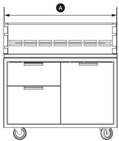
Technical line drawing of a two-door electrical cabinet with wheels and a labeled component (no text or symbols)CAD1-36/36E Front view
natural_image
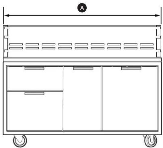
Technical line drawing of a multi-compartment container with wheels and side drawers, no text or symbols presentCAD1-48/48E Front view
text_image
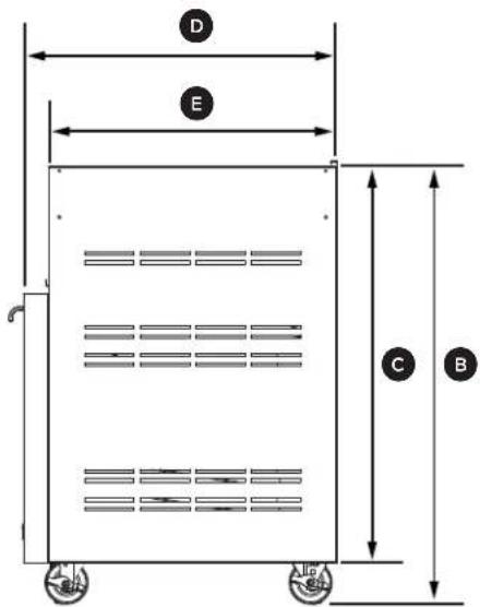
D E C BCAD1-30, CAD1-36/36E and CAD1-48/48E Side view
| PRODUCT DIMENSIONS | CAD1-30 CAD1-36/36E CAD1-48/48E | |||
| Inches (mm) | Inches (mm) | Inches (mm) | ||
| A | Overall width of cart | 30 (762) | 36 (914) | 48 (1219) |
| B | Overall height of cart | 3512 (902) | 3512 (902) | 3512 (902) |
| C | Height of cart chasis(excluding wheels) | 32 (816) | 32 (816) | 32 (816) |
| D | Overall depth of cart | 2512 (648) | 2512 (648) | 2512 (648) |
| E | Depth of cart chasis(excluding doors & handles) | 2312 (597) | 2312 (597) | 2312 (597) |
| F | Width of side shelf bracket | 412 (114) | 412 (114) | 412 (114) |
| G | Width of side shelf | 24 (610) | 24 (610) | 24 (610) |
Compatibility
IMPORTANT!
All Series 9 grills MUST only be used with either CAD1-36E or CAD1-48E model carts. They cannot be used with any other CAD1 carts. Series 7 grills can be used with both CAD1 and CAD1-E cart models.
Shipping inspection
IMPORTANT!
- Do not discard any packing material (box, straps) until the unit has been inspected.
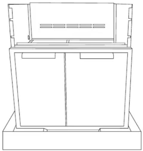
① Inspect the Cart to verify that there is no shipping damage.
② If any damage is detected, call the retail dealer and initiate a damage claim. DCS by Fisher & Paykel is not responsible for shipping damage.
- Operate the drawers to be sure they glide smoothly.
- Examine the drawer fronts to be sure there are no dents or scratches.
natural_image
Line drawing of a cabinet or enclosure with two doors and a top shelf, no text or symbols presentLocating the cart
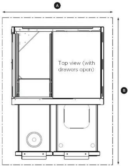
For proper use, this product should be installed/positioned on a flat ground or patio. Unevenness such as bumps, cracks and protrusions should be 14 " or less. Refer to illustration and the below table for required flat area dimensions.
| REQUIRED FLAT AREA | CAD1-36/36E | CAD1-48/48E | |
| Inches (mm) | Inches (mm) | ||
| A | Width | 36 (914) | 48 (1219) |
| B | Depth | 48 (1219) | 48 (1219) |
Cart assembly instructions
IMPORTANT!
- Some parts have sharp edges; care must be taken when handling the various components to avoid injury. Please read safety information provided in these instructions before beginning assembly. Wear gloves when handling.
- Two or more people should work together to assemble the cart and All-Grill, Double Side Burner/Sink, or Double Side Burner/Griddle.
- Avoid using side shelf to move cart. Push or pull the cart by grasping corners of head.
text_image
A Top view (with drawers open) BContent included
Your cart is packaged in one box. The box contains your cart and a universal hardware kit to be used for grill installation and may contain extra hardware for your convenience.
Table of quantity of parts
| CONTENTS MODEL PART NO. QTY. | |||
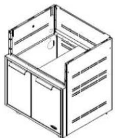 | CAD1-30 71131 1 | ||
| CAD1-36 | 71132 | 1 | |
| CAD1-36E | 71407 | 1 | |
| CAD1-48 | 71133 | 1 | |
| 30" Cart shown | CAD1-48E | 71408 | 1 |
| CONTENTS | CAD1-30 | CAD1-36/36E | CAD1-48/48E | |
| Machined Phillipscrews 10-24X1/2" | 13 | 16 | 17 | |
| Bracket, Tab | 2 | 2 | 4 | |
| Bolt Hex1/4-20-12" | 2 | 2 | 2 | |
| Washer.313 x .750 | 4 | 4 | 4 | |
| Nut Hex1/4-20 | 2 | 2 | 2 | |
Tools required
 | Eye Goggles |
 | Work Gloves |
 | Power Screwdriver or Variable Speed Drill with Phillips - tip #2 Attachment |
 | 5/32" Allen Wrench |
 | 3/16" Allen Wrench |
 | 3/32" Allen Wrench |
Cart assembly instructions
Linking carts together (optional)
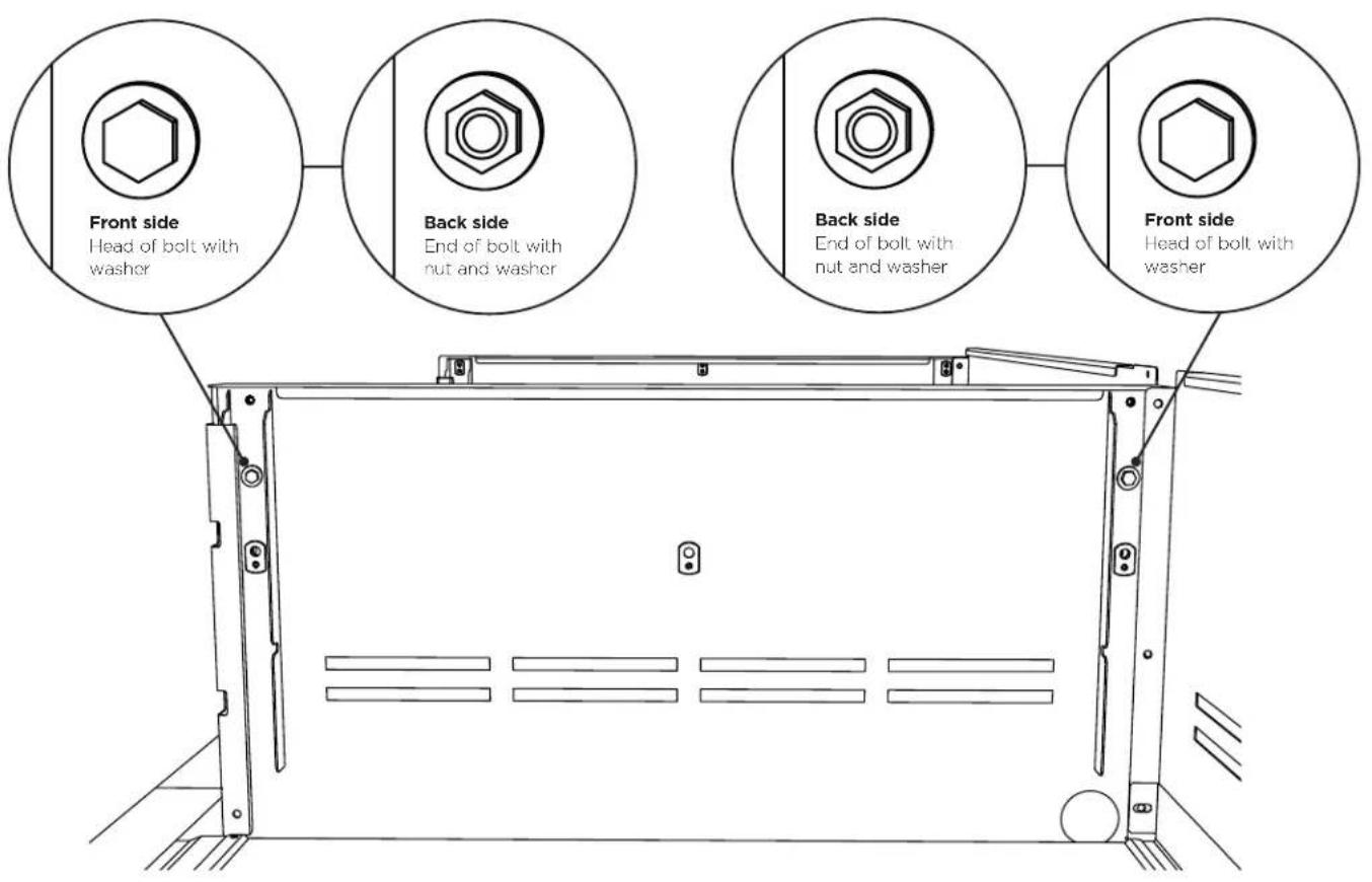
To link two or more CAD1 carts, the following instructions must be done first, using the hardware provided, before installing the top modules.
IMPORTANT!
Once the carts are linked, they cannot be moved. Moving the carts once linked could damage the carts.
text_image
Front side Head of bolt with washer Back side End of bolt with nut and washer Back side End of bolt with nut and washer Front side Head of bolt with washer① Hand tighten two bolts, four washers, and two nuts on the front and back sides of the carts as shown.
② Carefully wrench tighten fasteners once carts are aligned with each other.
Cart assembly instructions
Outdoor appliance head preparation
natural_image
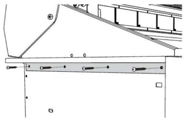
Technical line drawing of a structural support frame with diagonal bracing and horizontal beam (no text or symbols)① First you will need to remove the angle brackets from the side of the unit and replace them with cart mount brackets. Note: unit is shipped prepared for island installation.
natural_image
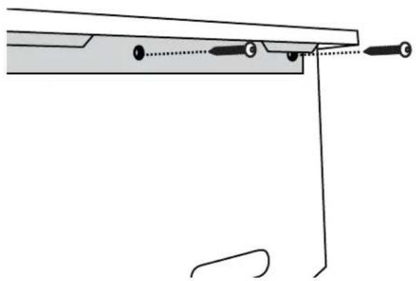
Pure mechanical diagram showing a lever and pivot point without any text, numbers, or symbols② Install the bracket tab on both sides using eight of the 10-24 x 1/2" screws. Install each bracket with four screws on each side of the grill head. For a CAD1-48/48E, use the appropriately labeled bracket for your grill head and cart side.
IMPORTANT!
For the CAD1-48/48E there are two sets of brackets. If you have the BGB48-BQR, use the brackets labeled LEFT-48 BQR and RIGHT-48 BQR. If you have the BGB48-BQAR, use the brackets labeled 48-BQAR.
Head placement onto cart - two persons required
IMPORTANT!
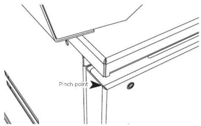
- Be aware of pinch points and sharp edges to avoid injury to arms and hand.
- Two persons required to lift head.
natural_image
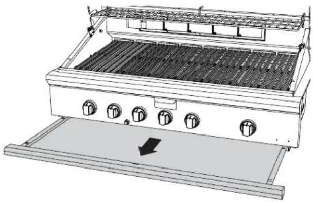
Technical line drawing of a portable stove or grating unit with control knobs and a downward arrow indicating airflow (no text or symbols present)① Remove drip tray/pan and other removable components such as grates, top burner caps and components, and griddle flue cover, radiant tray and grill burner for easier handling.
natural_image
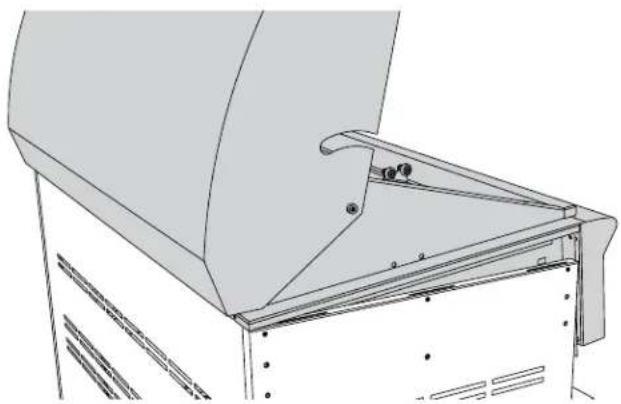
Technical line drawing of a mechanical assembly with no visible text or symbols② Placing head on cart, place rear of head over the rear of the cart first. Then allow the rear side tabs to first locate in the slots on the top of the cart sides. The other tabs will locate in the middle and front slots as the head is lowered into position on the cart.
Cart assembly instructions
text_image
Pinch point③ Position tabs on side bracket to fit into slots on the cart. When complete, the landing ledge should sit flush on the top of the cart.
natural_image
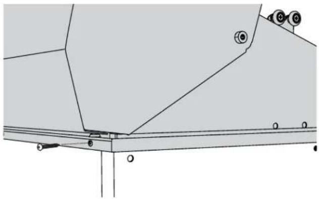
Technical line drawing of a mechanical assembly with mounting holes and structural beams (no text or symbols)④ Secure the head to rear of cart with Phillipshead screws provided (10-24 x 1/2").
Front end screw installation
natural_image
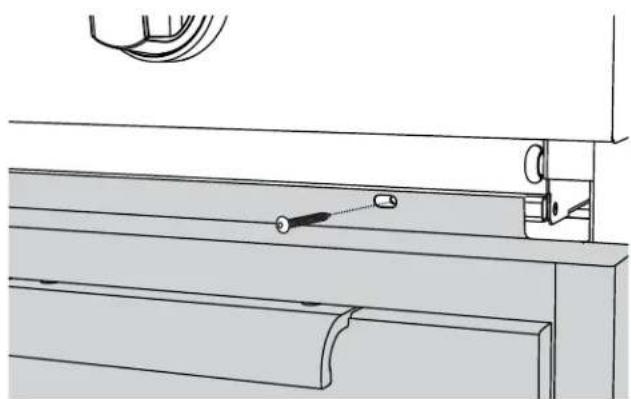
Technical line drawing of a mechanical assembly with no visible text or symbols① Install remaining screws (10-24 x 1/2") into the front of head to the cart.
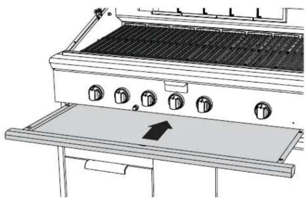
natural_image
Line drawing of a grating furnace with control knobs and a directional arrow indicator (no text or symbols)② Slide drip tray/pan back into place.
Transformer installation (for Series 9 grills only)
Your Series 9 grill comes supplied with a power transformer for ignition and internal lighting, which is concealed in a box with an attached power supply cord. It is recommended that the transformer is mounted to the rear panel of the CAD1-E cart using the 4 holes provided.
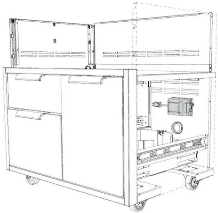
natural_image
Technical line drawing of a mechanical device with open cabin and internal components (no text or symbols)| HZ VOLTAGE (V) AMPS (A) | |
| 60 Hz 120V 15 | |
IMPORTANT!
Use only a Ground Fault Interrupter (GFI) protected circuit with this transformer.
The suggested location for installation is above the hole the transformer cord routes through, which is on the inside of the right-hand side of the cart's back panel. Remove the transformer from its bracket, and reuse the 4 nuts and bolts to attach the transformer to the cart.
Routing the transformer cord
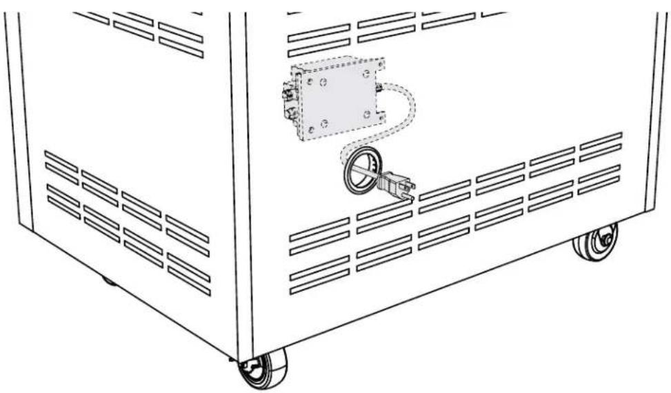
natural_image
Technical line drawing of a mechanical device with wheels and a central component (no text or symbols)Route the cord through the provided hole and connect to the nearest 120VAC 15A GFI (Ground Fault Interrupter) electrical outlet.
Cart assembly instructions
Gas hook-up - LP
Attach LP gas line connector hose assembly (as shown in "LP Gas Hook-up" section - The Professional Liberty Collection, Use/Care Guide) and then connect to LP tank as shown.
IMPORTANT!
- To prevent personal injury or damage to the drawers, do not overload them. The maximum rating of each drawer is 35 pounds.
- Do not push down on the top of the drawers. The unit could tip forward.
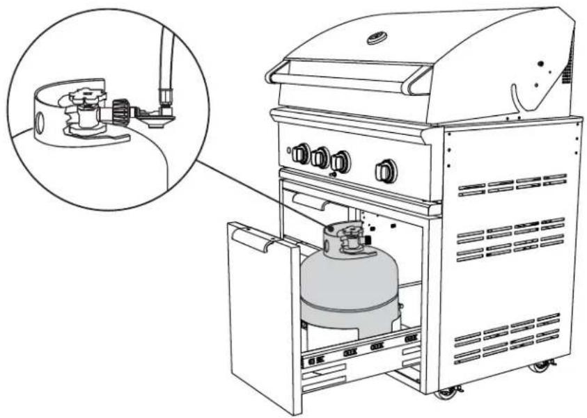
natural_image
Line drawing of an outdoor gas stove with a gas cylinder inside, showing internal components and a magnified inset (no text or symbols)Cover hanger
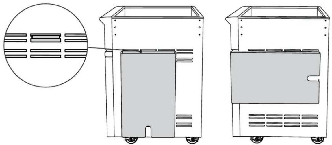
To use the cover hangers provided, first place the cover hanger into the slot on the side or rear of your cart then hang the cover in either direction as shown below.
IMPORTANT!
Do not move the cart while the covers are hung. This could cause the covers to fall off the hangers and damage the covers.
natural_image
Technical line drawing of a two-part electronic device with internal components and a magnified inset showing internal structure (no text or symbols)Side shelf assembly instructions (optional)
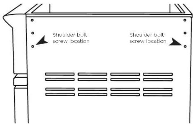
Optional attach side shelf accessory on either side
Note: side shelf model CAD1-SK can be installed with the head already on the cart.
text_image
Shoulder bolt screw location Shoulder bolt screw location① Screw two shoulder bolts into the bottom screws on the side of the cart. Tighten with 5/32 Allen wrench.
natural_image
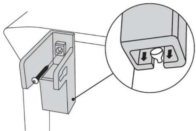
Technical diagram of a mechanical device with an inset showing internal components (no text or symbols)② Slide left and right side shelf brackets over the shoulder bolt and install top screw attaching the side shelf brackets onto the cart. Tighten with Phillips screwdriver.
natural_image
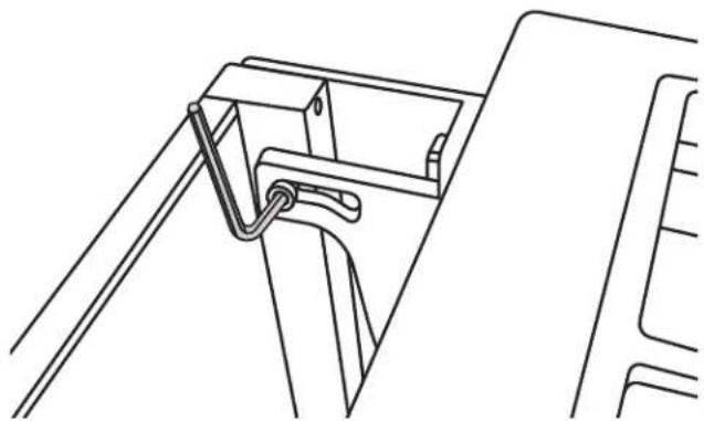
Technical line drawing of a mechanical bracket or bracket assembly (no text or symbols)③ Holding the side shelf, install two shoulder bolts into the slot and screw into the side shelf tray. Tighten with a 3/16 Allen wrench.
natural_image
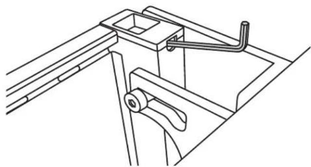
Technical line drawing of a mechanical bracket assembly (no text or symbols)④ Place shelf in the up position and check for level. If shelf is not level, adjust side shelf set screw. Set screws can be adjusted using a 3/32 Allen wrench. Turn the Allen wrench clockwise to raise the shelf. Turn 1/4 turn and review to see if the shelf is level. The set screws in the left and right bracket should be adjusted equally to ensure the shelf sits level.
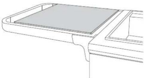
Optional wood cutting board (model # CAD1-WCB, 70861) can be purchased as an accessory from www.dcsappliances.com.
natural_image
Technical line drawing of a mechanical component or bracket (no text or symbols)Sink drain assembly instructions (optional)
Content included
Your Sink Drain Accessory Kit is packaged in one box. The box contains the following components:
Table of quantity of parts
| CONTENTS QTY. | CONTENTS QTY | ||||
 | GrayWaterTank | 1 |  | 3-1/2" Snao Bushing | 1 |
 | Snap Lock Clip | 1 | |||
| CONTENTS QTY |  | 1-1/2" Tailpiece Washer | 2 | ||
 | Tank Bracket | 1 |  | Fitting, 1/2 NPT x 3/4 ID Tube | 1 |
 | 3/4 HoseTank Drain | 1 |  | Nipple, 1-1/2" NPT | 1 |
 | 1/2" Ball Valve | 1 |  | Elbow, 3/4 NPT x 3/4 ID Tube | 1 |
 | Water HoseAdapter | 1 | |||
 Sink Drain Hose Assembly Sink Drain Hose Assembly | 1 | Tools required | |||
 Faucet Hose and Vent Tube Faucet Hose and Vent Tube | 1 |  | Work Gloves | ||
| [HABG] | Hose Clamp, 9/16" x 1-1/16" | 2 |  | Adjustable Pipe Wrench | |
 | Brass Fitting, 1/4 ID Tube x 1/8 NPT | 1 |  | Phillips Screw Driver | |
 Cable Tie Cable Tie | 1 |  | Flat Head Screw Driver | ||
Sink drain assembly instructions (optional)
IMPORTANT!
Remove all racks and drawers from the cart and grates. And remove burner caps and drip tray from the side burner/sink prior to kit installation.
natural_image
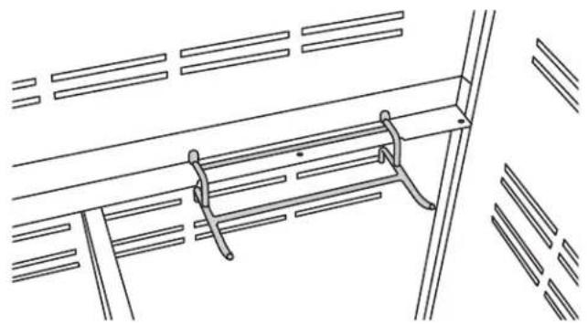
Technical line drawing of a structural support frame with diagonal braces and vertical supports (no text or symbols)① Attach tank bracket on the right side of the cart.
natural_image
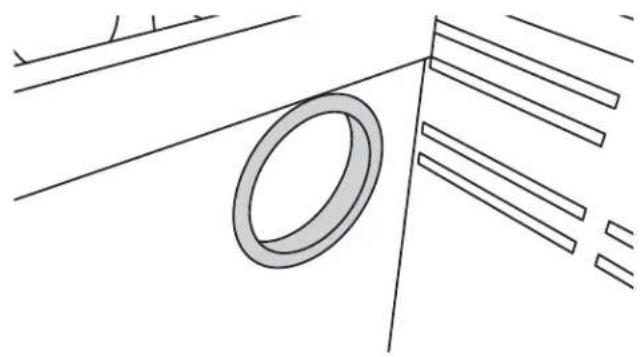
Pure technical line drawing of a ring and parallel lines without any text, numbers, or symbols② Install the snap bushing in the center divider.
natural_image
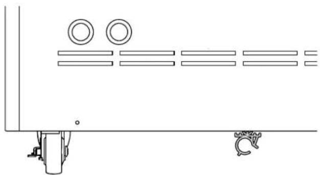
Technical line drawing of a mechanical assembly with two circular components and mounting base (no text or symbols)③ Install the snap-lock clip in the back bottom of the cart into the hole provided. Note the direction of installation.
text_image
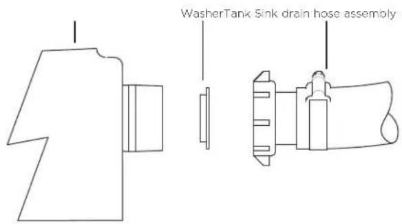
WasherTank Sink drain hose assembly④ Attach sink drain hose assembly to the tank (include one tailpiece washer).
natural_image
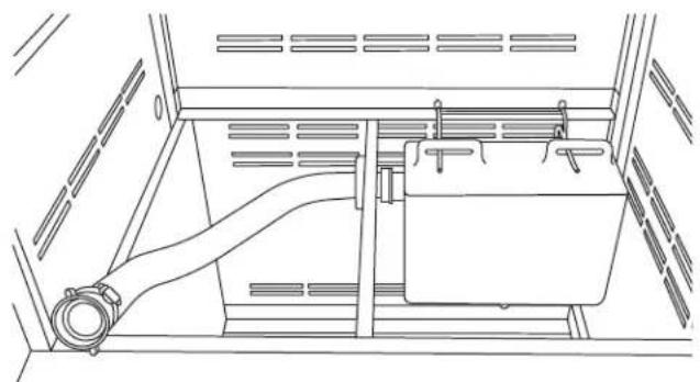
Technical line drawing of a mechanical assembly with a pipe and housing (no text or symbols)⑤ Install the tank/hose assembly in the cart, over the tank bracket and feed the sink drain hose through the hole in the center divider.
natural_image
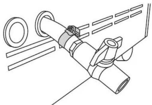
Technical line drawing of a mechanical assembly with pipes and fasteners (no text or symbols)⑥ The drain hose at the bottom of the tank exits the hole in the back of the cart. Attach the 1/2" ball valve and fitting to the tank and tighten the hose clamp.
Sink drain assembly instructions (optional)
IMPORTANT!
Finger tight first, then use a wrench.
text_image
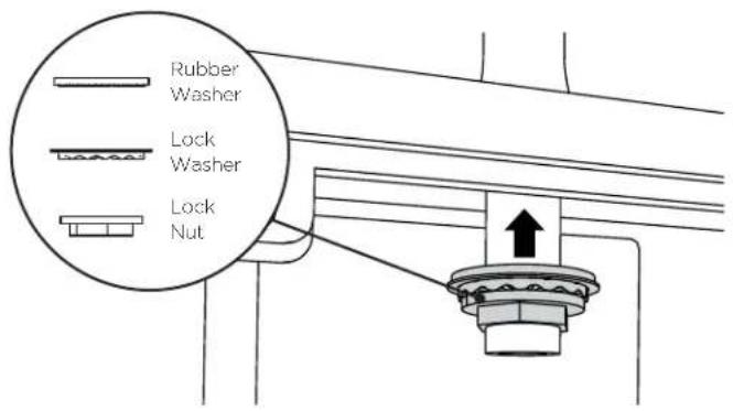
Rubber Washer Lock Washer Lock Nut⑦ Set the side burner/sink securely on a table and attach the faucet to the sink as shown.
natural_image
Technical line drawing of a mechanical assembly with no visible text or symbols⑧ Feed the three-foot water supply hose/air vent tube through the hole at the bottom of the burner box, and attach it to the faucet.
⑨ Outdoor appliance head preparation
IMPORTANT!
Excessive weight hazard. Use two or more people to move and install sink/burner assembly onto the cart.
natural_image
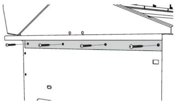
Technical line drawing of a mechanical assembly with no visible text or symbolsⒶ Remove the angle brackets from the side of the unit and replace them with cart mount brackets.
natural_image
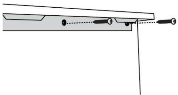
Pure mechanical assembly diagram showing a lever and pivot point without any text or symbols⑧ Install the bracket tab on both sides using eight of the 10-24 x 1/2" screws. Install each bracket with four screws on each side of the grill head. For a CAD1-48/48E, use the appropriately labeled bracket for your grill head and cart side.
Sink drain assembly instructions (optional)
⑩ Head placement onto cart
IMPORTANT!
Beware of pinch points and sharp edges to avoid injury to arms and hands.
natural_image
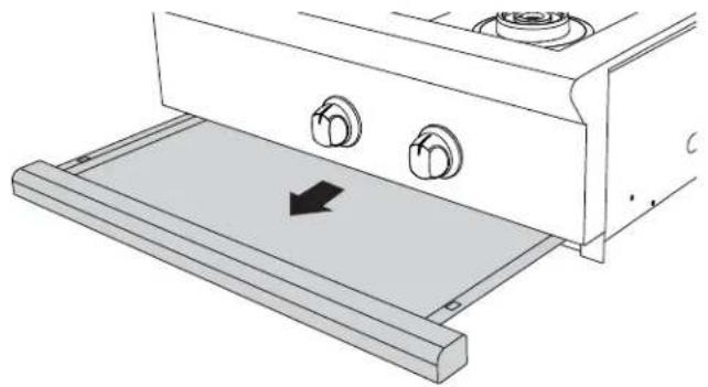
Technical line drawing of a kitchen appliance with two outlets and a tray, showing a black arrow indicating direction (no text or symbols)Ⓐ Remove drip tray/pan and other removable components such as grates, top burner caps and components, and griddle flue cover, radiant tray and grill burner for easier handling.
natural_image
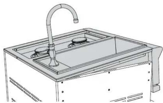
Technical line drawing of a stainless steel kitchen sink with a faucet and control panel (no text or symbols)⑧ Place rear of head over the rear of the cart first then allow the rear side tabs to first locate in the slots on the top of the cart sides. The other tabs will locate in the middle and front slots as the head is lowered into position.
natural_image
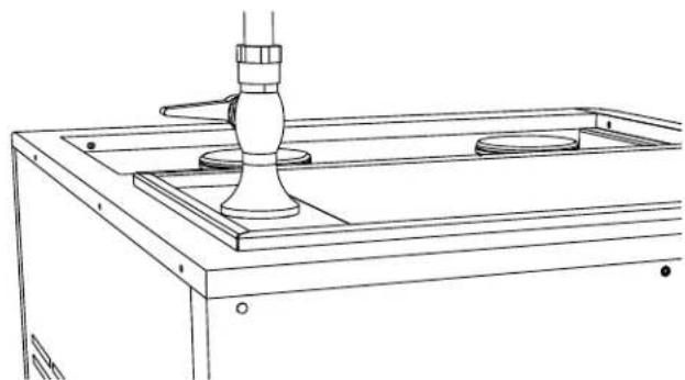
Line drawing of a mechanical setup with a cylindrical component mounted on a base plate (no text or symbols)© Position tabs on side bracket to fit into slots on the cart. When complete, the landing ledge should sit flush on the top of the cart.
natural_image
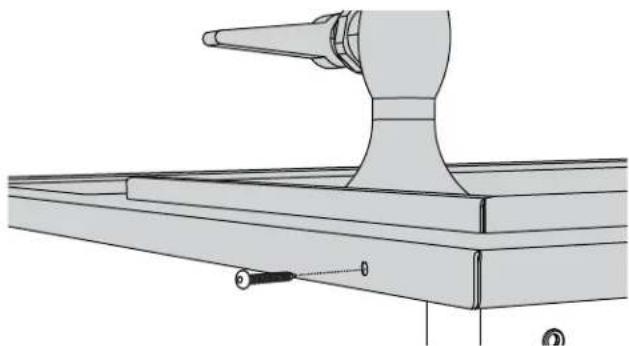
Technical line drawing of a mechanical assembly with a conical tool and base plate (no text or symbols)⑭ Secure the head to rear of cart with Phillipshead screws provided (10-24 x 1/2").
natural_image
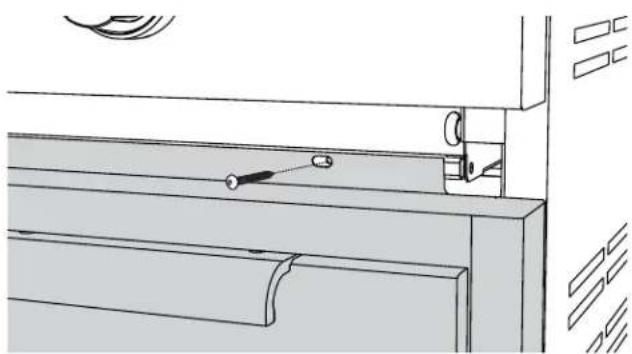
Technical line drawing of a mechanical assembly with no visible text or symbols⑤ Install remaining three screws (10-24 x 1/2") into the front of head to the cart.
natural_image
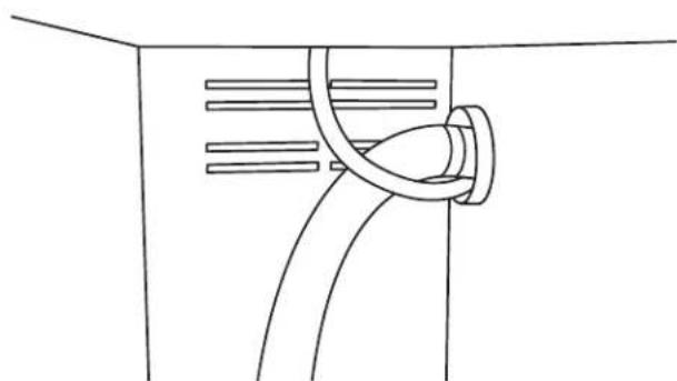
Pure technical line drawing of a mechanical or electrical component with no text, numbers, or symbols⑪ Feed the water supply hose through the center divider hole, down to the bottom opening of the cart.
Sink drain assembly instructions (optional)
IMPORTANT!
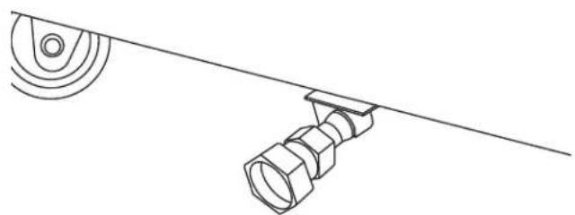
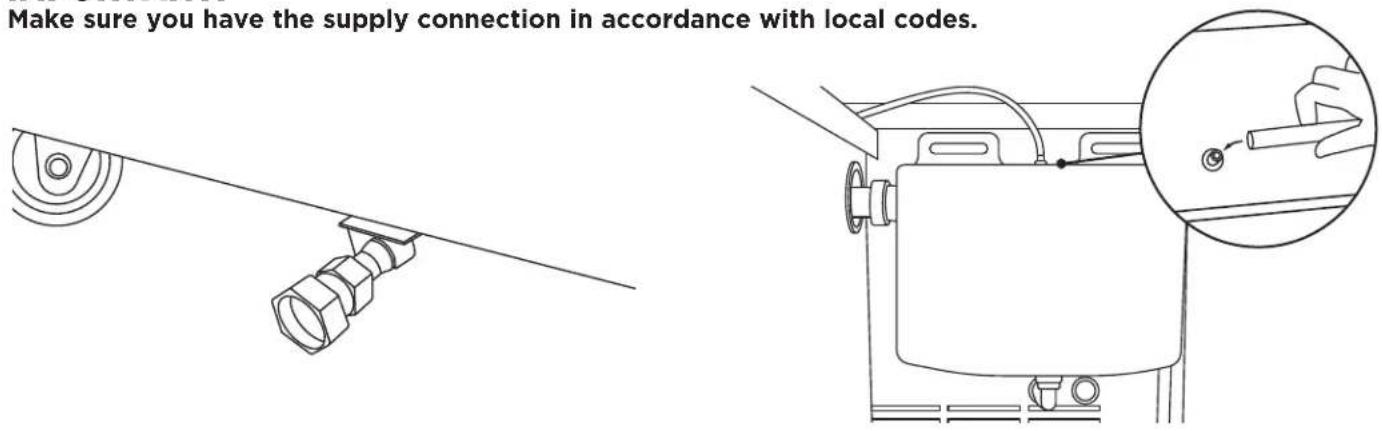
Make sure you have the supply connection in accordance with local codes.
natural_image
Technical line drawing of a mechanical component with a threaded fastener and a rotating wheel (no text or symbols)⑫ Place the end of the water supply hose in the snap-lock clip and lock it in place. Attach the water hose adapter.
text_image
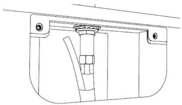
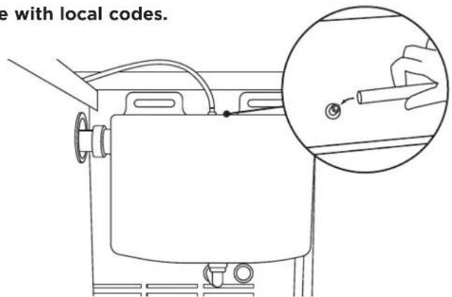
e with local codes.⑬ Feed the air vent tube over the center divider and attach it to the brass fitting located at the top of the water tank.
text_image
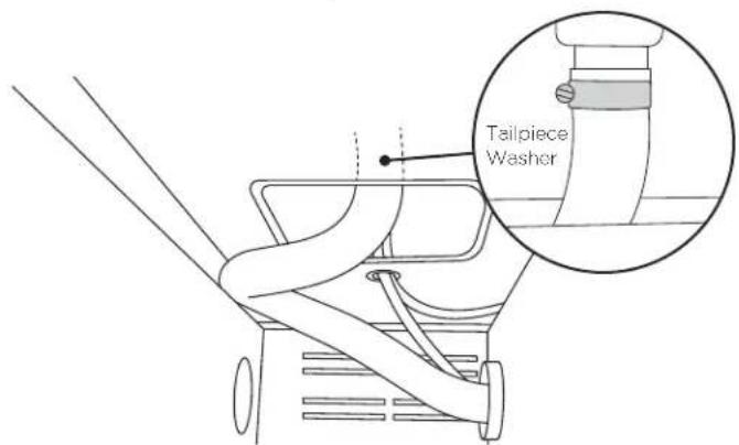
Tailpiece Washer⑭ Attach the sink drain hose to the bottom of the sink (use one tailpiece washer) and push the sink drain hose up and over the edge of the side panel. This will prevent the interference between this hose and the top rack. It also creates proper drainage from the sink to the water tank. And/or use the cable tie provided to hold the hose up.
natural_image
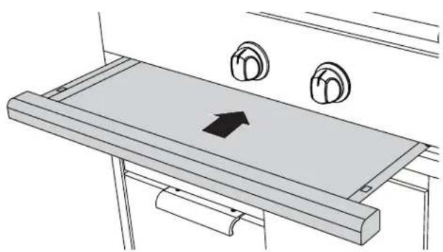
Technical line drawing of a mechanical assembly with two circular components and an arrow indicating direction (no text or symbols)⑮ Slide drip tray/pan back into place and reinstall parts removed in step 10A.
⑯ Attach cold water hose (not supplied) to the unit and test the system for leaks.
- Close the ball valve behind the cart.
- Turn on the faucet.
- Check all connections inside and outside the cart.
- If you notice any leaks, turn the water supply off. Tighten connections that are leaking and retest.
Removing the drawers
IMPORTANT!
To prevent personal injury or damage to the drawers, do not overload them. The maximum rating of each drawer is 35 pounds.
natural_image
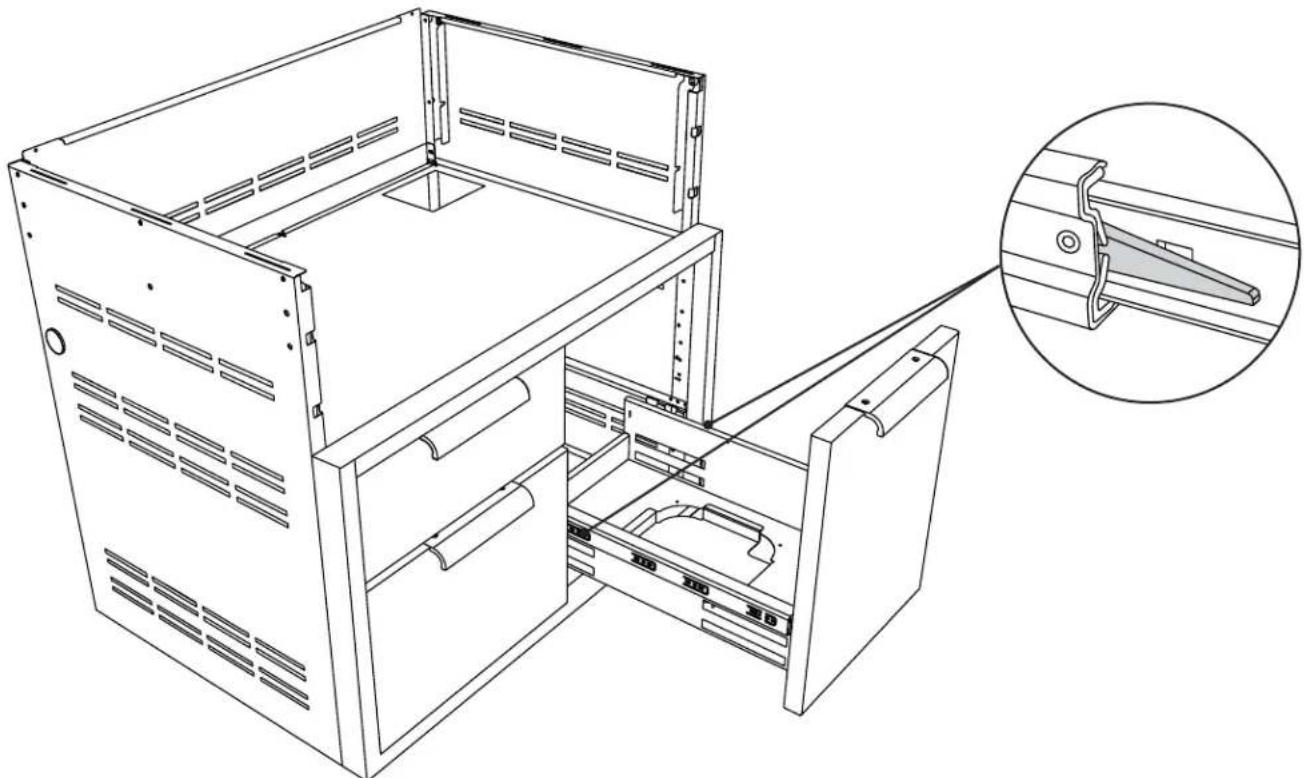
Technical line drawing of a computer rack cabinet with an inset close-up showing internal components (no text or symbols)① To remove the drawers, pull them out until their slider latch is visible. Carefully push the latch down on the left side while pulling up on the latch on the right side and pull the drawer completely out of the frame.
② To prevent damage to surfaces, place the drawers on a stable surface on a protective towel or tablecloth while removed from the cart.
Re-installing the drawers
natural_image
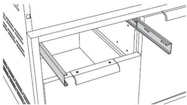
Technical line drawing of a mechanical assembly with no visible text or symbols① Re-install the drawers by extending their guides.
natural_image
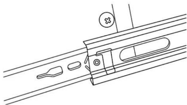
Technical line drawing of a mechanical assembly with no visible text or symbols② While holding the drawer parallel to the cabinet, carefully align & engage the ends of the glides. Slide the drawer about an inch so that the glides are supporting the back of the drawer.
Re-installing the drawers
natural_image
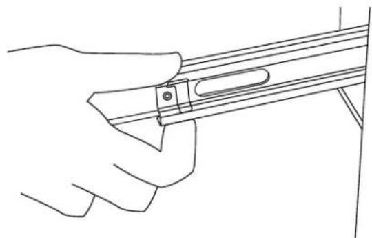
Line drawing of a hand holding a tool or bracket with a clip, no text or symbols present① While holding the drawer up by the handle, pull the glides from the drawer cavity out over the drawer glide until they click.
natural_image
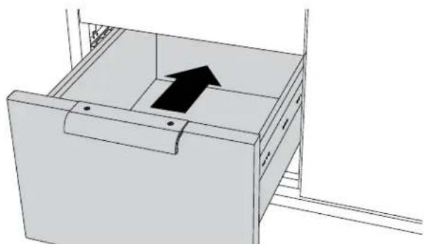
3D diagram of a drawer with an arrow indicating direction, no text or symbols present② As you push the drawers in, you will encounter moderate resistance. Continue to push the drawer all the way in to complete the engagement process. The drawer will now glide smoothly in and out with light effort.
text_image
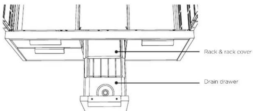
Rack & rack cover Drain drawer③ Install the two racks provided into the opening by sliding them onto the rollers on the sidewalls of the left cavity.
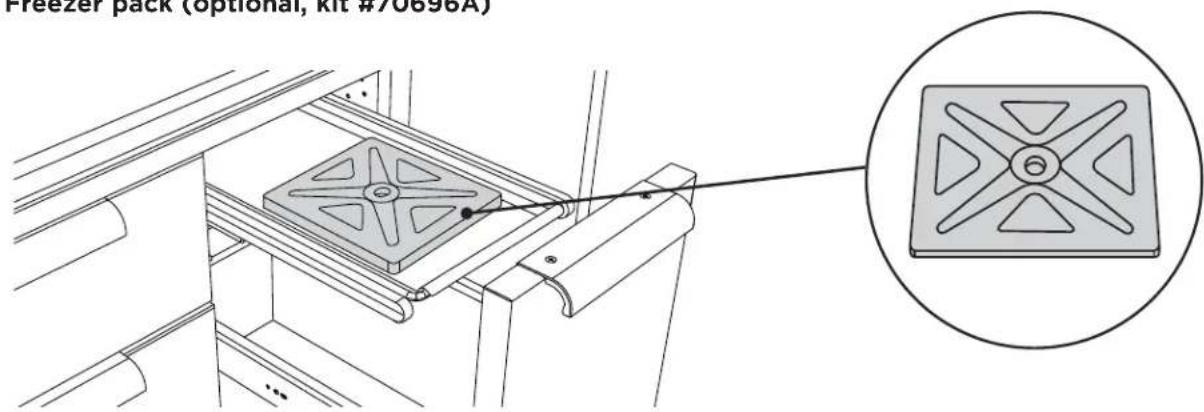
Freezer pack (optional, kit #70696A)
text_image
Freezer pack (optional, kit #70896A)① Place the freezer pack in freezer, laying it flat.
② Freeze overnight or a minimum of eight hours.
③ Place frozen freezer pack in the steel tray on the second shelf, in appropriate cavity of the drawer. The freezer pack is dishwasher safe. Or wash with warm soapy water, rinse and air dry. Store flat in dry storage or in freezer.
All parts of the Professional Grill Cart can be cleaned with hot soapy water, rinsed, dried and buffed to a shine with a soft, heavy cloth. Always try this first, as it is the mildest cleaning procedure.
① Use the mildest cleaning procedure first. Some brands of cleaners of the same type are harsher than others, read their directions. A scent or a propellant can make a difference in the product, read the ingredients. Try on a small area first.
Caution should be taken to keep the regulator free from any cleaning soaps or water.
② To avoid marring the surface, always rub metal finishes in the direction of the stainless steel polish lines (grain). The cleaner will be more effective when used in the direction of the polish lines.
③ Use only clean sponges, soft cloths, paper towels, plastic non-metal soap pads for cleaning or scouring as recommended in this section. (Use only soap pads with soap still in them. An empty pad can scratch.)
④ Be sure to rinse all parts thoroughly and to wipe dry to avoid water marks.
⑤ After cleaning, use a stainless steel polish, such as Stainless Steel Magic ^® applied to the drawer and handle surfaces.
Brand name cleaners
In this section on cleaning, the use of name brands is intended only to indicate a type of cleaner. This does not constitute an endorsement. The omission of any name brand cleaner does not imply its adequacy or inadequacy. Many products are regional in distribution and can be found in local markets and department stores.
SERVICE
For warranty service, please contact your local service provider or DCS Customer Care Representative at www.dcsappliances.com, please have the following information ready:
- Model number (can be found on the inside, left wall of the tank drawer).
- Serial number (can be found on the inside, left wall of the tank drawer).
• Code (can be found on the inside, left wall of the tank drawer).
• Date of installation.
• A brief description of the problem.
Your satisfaction is of the utmost importance to us. If a problem cannot be resolved to your satisfaction, please write or email us at:
Write
Fisher & Paykel Appliances Inc. Attention: DCS Customer Care 695 Town Center Drive, Suite 180 Costa Mesa. CA 92626-1902 USA
customer.care@fisherpaykel.com
Complete and keep for safe reference:
Model
Serial No. ____
Purchase Date
Purchaser
Dealer
Suburb
Town
Country ____
natural_image
Technical line drawing of a multi-compartment container with wheels and a labeled dimension (no text or symbols)natural_image
Technical line drawing of a multi-compartment container with wheels and side compartments (no text or symbols)natural_image
Technical line drawing of a mechanical or architectural component with no visible text or symbolsnatural_image
Technical line drawing of a structural support frame with diagonal bracing and horizontal beam (no text or symbols)natural_image
Pure mechanical diagram showing a lever and pivot point without any text, numbers, or symbolsnatural_image
Technical line drawing of a portable stove or grating unit with control knobs and a downward arrow indicating airflow (no text or symbols present)natural_image
Technical line drawing of a kitchen sink with faucet and control panel (no text or symbols)natural_image
Technical line drawing of a mechanical assembly with mounting holes and structural beams (no text or symbols)natural_image
Technical line drawing of a mechanical assembly with no visible text or symbolsnatural_image
Line drawing of a grating furnace with control knobs and a directional arrow indicator (no text or symbols)natural_image
Technical line drawing of a mechanical device with open cabin and internal components (no text or symbols)| HZ TENSION (V) | INTENSITÉ (A) |
| 60 Hz 120 V 15 |
IMPORTANT!
natural_image
Technical line drawing of a mechanical device with a central component and wheels (no text or symbols)natural_image
Line drawing of a gas stove with an inset showing internal components (no text or symbols)natural_image
Technical line drawing of a two-part electronic device with internal components and a magnified inset showing internal structure (no text or symbols)INSTALLATION
natural_image
Technical diagram of a mechanical device with an inset close-up showing internal components (no text or symbols)natural_image
Technical line drawing of a mechanical bracket assembly (no text or symbols)natural_image
Technical line drawing of a mechanical assembly with lever and bracket (no text or symbols)natural_image
Technical line drawing of a mechanical component or bracket (no text or symbols)natural_image
Technical line drawing of a structural support frame with diagonal braces and vertical supports (no text or symbols)natural_image
Pure technical line drawing of a ring and parallel lines without any text, numbers, or symbolsnatural_image
Pure technical line drawing of a mechanical assembly with no text or symbolsnatural_image
Technical line drawing of a mechanical assembly with hoses and a central component (no text or symbols)natural_image
Technical line drawing of a mechanical assembly with pipes and fasteners (no text or symbols)natural_image
Technical line drawing of a mechanical assembly with no visible text or symbolsnatural_image
Technical line drawing of a mechanical assembly with no visible text or symbolsnatural_image
Pure mechanical assembly diagram showing a lever and pivot point without any text or symbolsnatural_image
Technical line drawing of a kitchen appliance with a directional arrow indicating movement (no text or symbols)natural_image
Technical line drawing of a stainless steel kitchen sink with faucet and two circular fixtures (no text or symbols)natural_image
Line drawing of a mechanical assembly with a central cylindrical component and two circular components on a base (no text or symbols)natural_image
Technical line drawing of a mechanical assembly with no visible text or symbolsnatural_image
Technical line drawing of a mechanical assembly with no visible text or symbolsnatural_image
Pure technical line drawing of a mechanical component with no text or symbolsMake sure you have the supply connection in accordance with local codes.
natural_image
Technical line drawing of a mechanical assembly with two circular components and an arrow indicating direction (no text or symbols)natural_image
Technical line drawing of a computer chassis with internal components and an inset close-up showing a mechanical component (no text or symbols present)natural_image
Technical line drawing of a mechanical assembly with two metal brackets and mounting holes (no text or symbols)natural_image
Pure technical line drawing of a mechanical assembly with no text or symbolsnatural_image
Line drawing of a hand holding a tool or bracket with a clip, no text or symbols presentnatural_image
3D diagram of a drawer with an arrow indicating direction, no text or symbols presentFisher & Paykel Appliances Inc.
Attention: DCS Customer Care
695 Town Center Drive, Suite 180
Costa Mesa. CA 92626-1902 USA
customer.care@fisherpaykel.com
Copyright © Fisher & Paykel 2018. All rights reserved.
The product specifications in this booklet apply to the specific products and models described at the date of issue. Under our policy of continuous product improvement, these specifications may change at any time. You should therefore check with your Dealer to ensure this booklet correctly describes the product currently available.