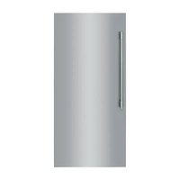
FPRU19F8WSS - Refrigerator FRIGIDAIRE - Free user manual and instructions
Find the device manual for free FPRU19F8WSS FRIGIDAIRE in PDF.


| Product Type | Built-in Refrigerator (and Freezer), compatible with trim kit |
| Brand | Frigidaire |
| Model | FPRU19F8WSS |
| Cutout Dimensions (Single Cabinet) | Width: 33" ± 0.032"; Height: 79" ± 0.06" or 83.75" ± 0.06"; Min. Depth: 25.25" |
| Cutout Dimensions (Double Cabinet) | Width: 66.25" ± 0.032"; Available Heights: 75", 79" or 84" |
| Electrical Supply | Two separate grounded duplex wall outlets required (for refrigerator and freezer) |
| Water Connection | Requires recessed water shut-off valve; optional water filter kit (TTFLTRICEKIT) |
| Main Features | Adjustable roller leveling system; compatibility with single or double trim kits; matching kit with heating blocks |
| Trim Material | Stainless steel |
| Care and Cleaning | Clean with non-abrasive soapy water; rinse with clear water; use non-abrasive stainless steel cleaner (e.g. Frigidaire ReadyClean™); never use chlorine |
| Safety | Wear safety glasses when using power tools; appliances are heavy – two people required for installation |
| Spare Parts and Repairability | Complete list of hardware components provided (tie bars, brackets, screws, etc.); part numbers are referenced |
| General Information | User manual and instruction guide available in PDF; online support via user questions |
Frequently Asked Questions - FPRU19F8WSS FRIGIDAIRE
User questions about FPRU19F8WSS FRIGIDAIRE
0 question about this device. Answer the ones you know or ask your own.
Ask a new question about this device
Download the instructions for your Refrigerator in PDF format for free! Find your manual FPRU19F8WSS - FRIGIDAIRE and take your electronic device back in hand. On this page are published all the documents necessary for the use of your device. FPRU19F8WSS by FRIGIDAIRE.
USER MANUAL FPRU19F8WSS FRIGIDAIRE
Single-Door All Refrigerator and All Freezer Trim Kit Installation
Product Line: All Refrigerator and All Freezer Models Serial Number Range: All Serial Number Ranges
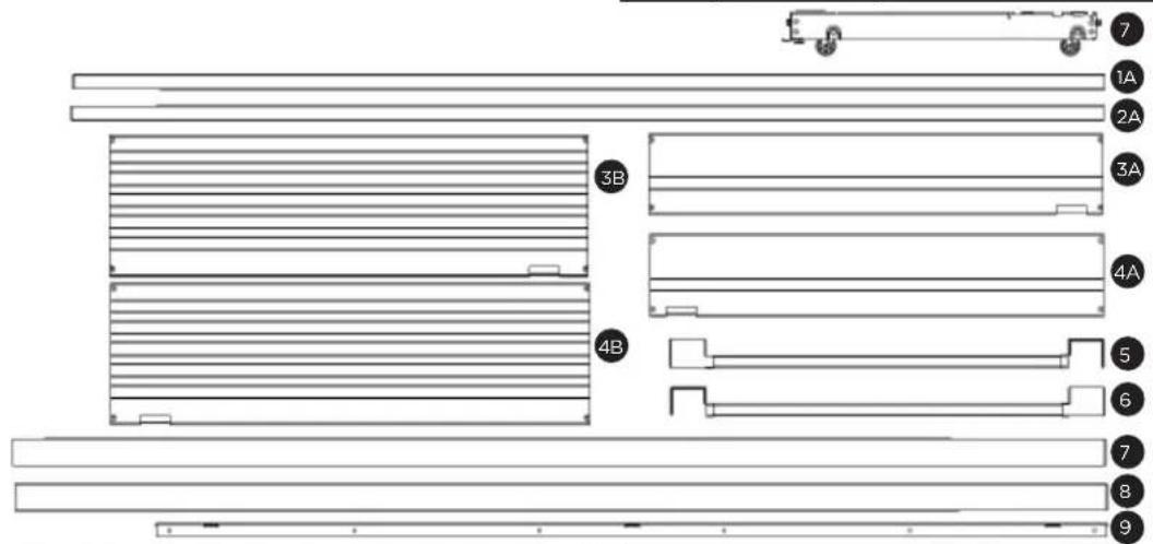
Single Trim Kit Components (79" & 84" Tall Cabinet Cutouts)
| Brand Kit # Single Trim Kit # | ||||
| Frigidaire Professional TRMKTEZIFL79 A16405201 | ||||
| Item # | Part Number Description Qty | |||
| 1A | A18684901 Side Trim, RH 1 | |||
| 2A | A18684902 Side Trim, LH 1 | |||
| 3A | A16766503 | Top Trim, Flat RH | 1 | |
| 4A | A16766505 | Top Trim, Flat LH | 1 | |
| 5 | A18684505 | Toe Kick, RH | 1 | |
| 6 | A18684507 | Toe Kick, LH | 1 | |
| 7 | A17111301 | Leveler Assembly | 2 | |
| 8 | A20841303 | Hardware Pack U19, Single | 1 | |
| Brand | Kit # | Single Trim Kit # | |
| Electrolux | TRMKTSSILV84 | A19895901 | |
| Item # | Part Number | Description Qty | |
| 1B | A19036503 | Side Trim, RH | 1 |
| 2B | A19036504 | Side Trim, LH | 1 |
| 3B | A19036402 | Top Trim, Louver RH | 1 |
| 4B | A19036403 | Top Trim, Louver LH | 1 |
| 5 | A18684506 | Toe Kick, RH | 1 |
| 6 | A18684508 | Toe Kick, LH 1 | |
| 7 | A17111301 | Leveler Assembly | 2 |
| 8 | A20841304 | Hardware Pack U19, Single | 1 |
| 9 | A19036701 Side Trim Attachment | 2 | |
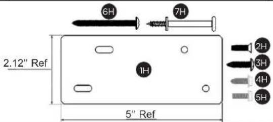
| Hardware Pack A20841303 | |||
| ITEM | PART NUMBER | DESCRIPTION | QTY |
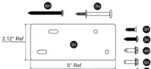
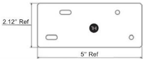
| 1H | A18695801 | Tie-Bar, Top | 1 |
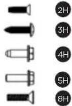
| 2H | 297142600 | Screw, Flathead, #8-32 | 2 |
| 3H | 050149 | Screw, Round, #8-18 | 4 |
| 4H | A16955502 | Bolt, M5 x 16 | 6 |
| 5H | A21188301 Bolt, 1⁄4-20 | 2 | |
| 6H, 7H | A20706101 | Trim Base Screw | 1 |
NOTE: All Hardware Pack components mentioned throughout this instruction sheet will have an "H" after the item number.
| Hardware Pack A20841304 | |||
| ITEM | PART NUMBER | DESCRIPTION | QTY |
| 1H | A18695801 | Tie-Bar, Top | 1 |
| 2H | 297142600 | Screw, Flathead, #8-32 | 2 |
| 3H | 050149 | Screw, Round, #8-18 | 12 |
| 4H | A16955502 | Bolt, M5 x 16 | 6 |
| 5H | A21188301 Bolt, 1⁄4-20 | 2 | |
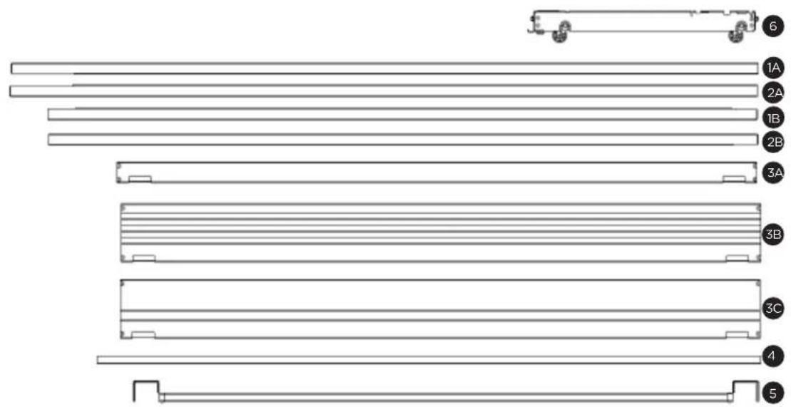
Dual Trim Kit Components (75" & 79" Tall Cabinet Cutouts)
| Brand Kit # Dual Trim Kit # | ||||
| Frigidaire TRMKTEZ2FL75 A18643301 | ||||
| Item # | Part Number Description Qty | |||
| 1B | A18685001 Side Trim, RH 1 | |||
| 2B | A18685002 Side Trim, LH 1 | |||
| 3A | A18694901 Top Trim, Collar | |||
| 4 | A18685101 | Center Trim | 1 | |
| 5 | A18684501 Toe Kick | |||
| 6 | A17111301 | Leveler Assembly | 4 | |
| 7 | A20841301 Hardware Pack U19, Single | |||
| Brand | Kit # | Dual Trim Kit # | ||
| Frigidaire | TRMKTEZ2LV79 | A16405401 | ||
| Item # | Part Number Description Qty | |||
| 1A | A18684901 Side Trim, RH | |||
| 2A | A18684902 Side Trim, LH | 1 | ||
| 3B | A18804301 Top Trim, Louver | |||
| 4 | A18685101 | Center Trim | 1 | |
| 5 | A18684501 Toe Kick | |||
| 6 | A17111301 | Leveler Assembly | 4 | |
| 7 | A20841301 Hardware Pack U19, Single | |||
| Brand Kit # Dual Trim Kit # | ||||
| Frigidaire TRMKTEZ2FL79 A16404901 | ||||
| Item # | Part Number Description Qty | |||
| 1A | A18684901 Side Trim, RH 1 | |||
| 2A | A18684902 Side Trim, LH 1 | |||
| 3C | A16766501 Top Trim, Flat 1 | |||
| 4 | A18685101 | Center Trim | 1 | |
| 5 | A18684501 Toe Kick | |||
| 6 | A17111301 | Leveler Assembly | 4 | |
| 7 | A20841301 Hardware Pack U19, Single | |||
| Brand | Kit # | Dual Trim Kit # | ||
| Electrolux | TRMKTSS2FL79 | A16404902 | ||
| Item # | Part Number Description Qty | |||
| 1A | A18684903 | Side Trim, RH | 1 | |
| 2A | A18684904 | Side Trim, LH | 1 | |
| 3C | A16766502 | Top Trim, Flat | 1 | |
| 4 | A18685102 Center Trim | 1 | ||
| 5 | A18684502 | Toe Kick | 1 | |
| 6 | A17111301 | Leveler Assembly | 4 | |
| 7 | A20841301 Hardware Pack U19, Single | |||
| Hardware Pack A20841301 | |||
| ITEM | PART NUMBER | DESCRIPTION | QTY |
| 1H | A18695801 Tie-Bar, Top | 1 | |
| 2H | 297142600 Screw, Flathead, #8-32 | 2 | |
| 3H | 050149 | Screw, Round, #8-18 | 4 |
| 4H | A16955502 | Bolt, M5 x 16 | 6 |
| 5H | A21188301 | Bolt, 1⁄4-20 | 2 |
| 6H, 7H | A20706101 | Trim Base Screw | 1 |
| 8H | A20632701 | Screw, 10-24 x 3⁄4 | 8 |
| 9H | A16770801 Tie Bar, Bottom | 2 | |
| 10H | A18685301 Center Trim Support | 1 | |

Dual Trim Kit Components (84" Tall Cabinet Cutouts)
| Brand Kit # Dual Trim Kit # | ||||
| Electrolux TRMKTSS2LV84 A16405301 | ||||
| Item # | Part Number Description Qty | |||
| 1A | A19036501 Side Trim, RH 1 | |||
| 2A | A19036502 Side Trim, LH 1 | |||
| 3A | A19036401 Top Trim, Louver 1 | |||
| 4 | A18685102 | Center Trim | 1 | |
| 5 | A18684502 Toe Kick | 1 | ||
| 6 | A17111301 | Leveler Assembly | 4 | |
| 7 | A20841302 Hardware Pack U19, Double | 1 | ||
| 8 | A19036701 Side Trim Attachment | 2 | ||

| Hardware Pack A20841301 | |||
| ITEM P | ART NUMBER DESCRIPTION QTY | ||
| 1H | A18695801 Tie-Bar, Top 1 | ||
| 2H | 297142600 Screw, Flathead, #8-32 2 | ||
| 3H | 050149 Screw, Round, #8-18 12 | ||
| 4H | A16955502 Bolt, M5 x 16 14 | ||
| 5H | A21188301 Bolt, 1⁄4-20 4 | ||
| 8H | A20632701 Screw, 10-24 x 3⁄4 8 | ||
| 9H | A16770801 Tie Bar, Bottom 2 | ||
| 10H | A18685301 Center Trim Support 1 | ||

Single Trim Kits (79" & 84" Tall Cabinet Cutouts)
TRMKTEZ1FL79 (Frigidaire) TRMKTSS1LV84 (Electrolux)

IMPORTANT
Make sure there are two separate dedicated grounding-type duplex wall outlets for the freezer and the refrigerator as specified in the Use & Care Manual.
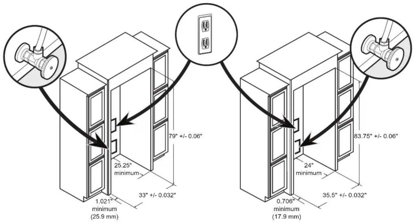
Cabinet Cutout Dimensions
Use these dimensions to build kitchen cabinet openings for the refrigerator and freezer.
Single Trim Kits (79" & 84" Tall Cabinet Cutouts)
TRMKTEZ1FL79 (Frigidaire) TRMKTSS1LV84 (Electrolux)

IMPORTANT
Make sure there are two separate dedicated grounding-type duplex wall outlets for the freezer and the refrigerator as specified in the Use & Care Manual.
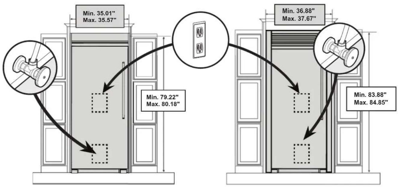
Trim Kit Finished Dimensions
Use these dimensions to layout adjoining cabinet door, drawers, and shelves.
Dual Trim Kits (75" & 79" Tall Cabinet Cutouts)

IMPORTANT
Use two recessed duplex electrical outlets and a recessed water shutoff valve for a 24" minimum opening. For new construction, use a 25.25" cabinet depth dimension.

NOTE
To install a dual trim kit or a pairing kit, a partition cannot exist between the Freezer and the Refrigerator.
TRMKTEZ2FL75 (Frigidaire)
TRMKTEZ2FL79 (Frigidaire)
TRMKTSS2FL79 (Electrolux)
TRMKTEZ2LV79 (Frigidaire)
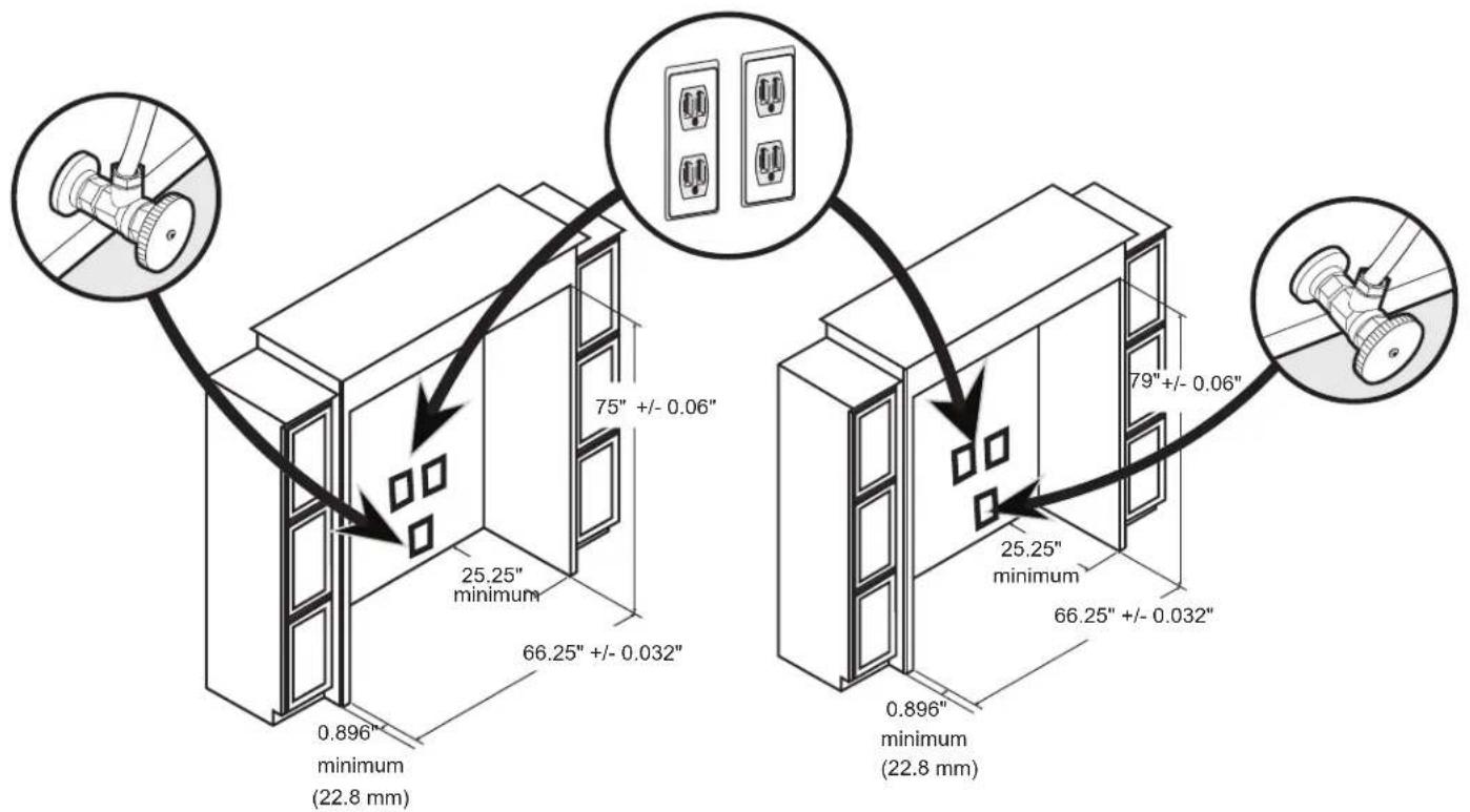
Cabinet Cutout Dimensions
Use these dimensions to build kitchen cabinet openings for the refrigerator and freezer.
Dual Trim Kits (75" & 79" Tall Cabinet Cutouts)

IMPORTANT
Use two recessed duplex electrical outlets and a recessed water shutoff valve for a 24" minimum opening. For new construction, use a 25.25" cabinet depth dimension.

NOTE
To install a dual trim kit or a pairing kit, a partition cannot exist between the Freezer and the Refrigerator.
TRMKTEZ2FL75 (Frigidaire)
TRMKTEZ2FL79 (Frigidaire)
TRMKTSS2FL79 (Electrolux)
TRMKTEZ2LV79 (Frigidaire)
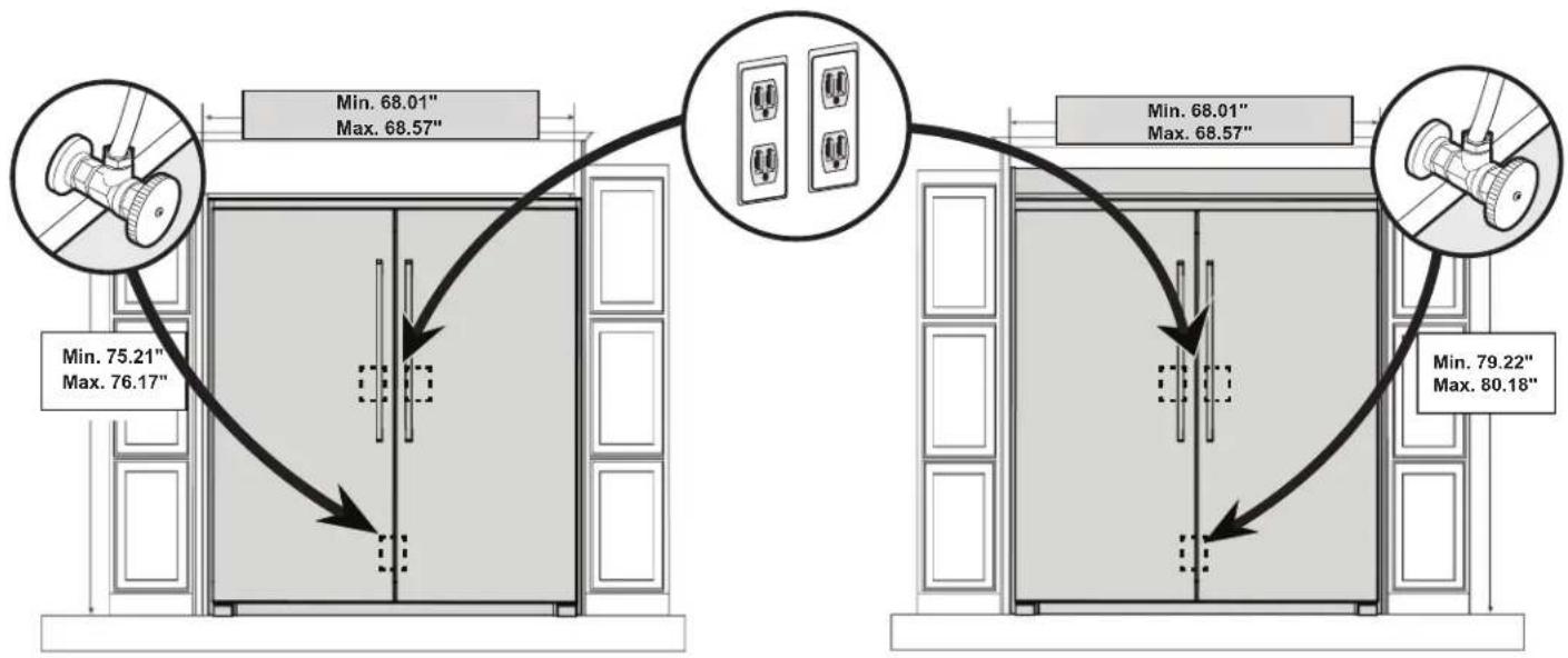
Trim Kit Finished Dimensions
Use these dimensions to layout adjoining cabinet door, drawers, and shelves.
Dual Trim Kits (84" Tall Cabinet Cutouts)
TRMKTSS2LV84 (Electrolux)
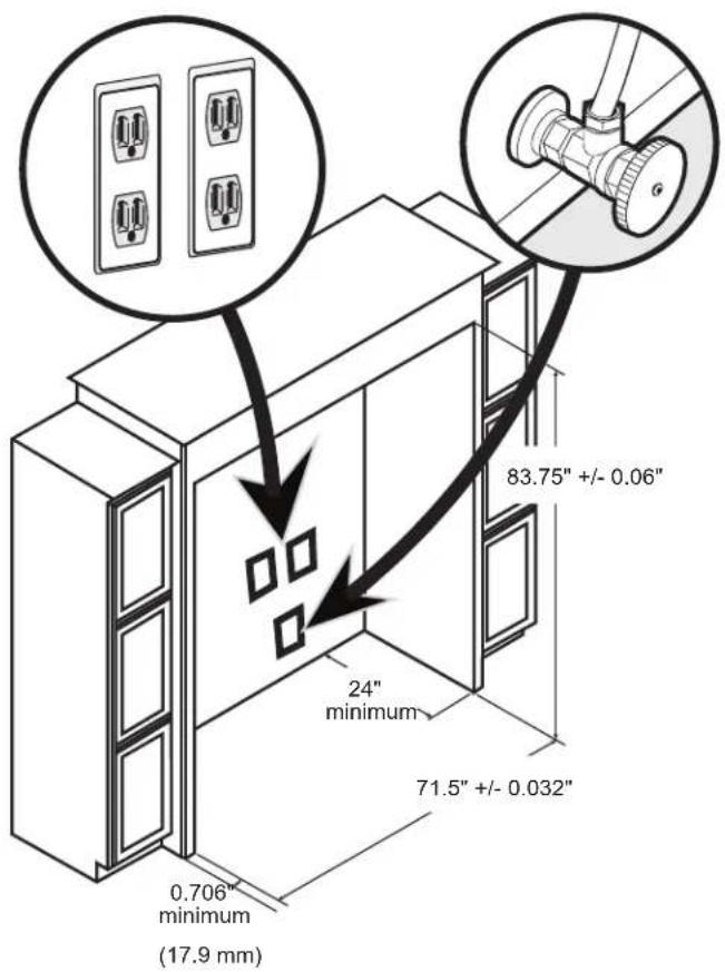
Cabinet Cutout Dimensions
Use these dimensions to build kitchen cabinet openings for the refrigerator and freezer.
Dual Trim Kits (84" Tall Cabinet Cutouts)
TRMKTSS2LV84 (Electrolux)
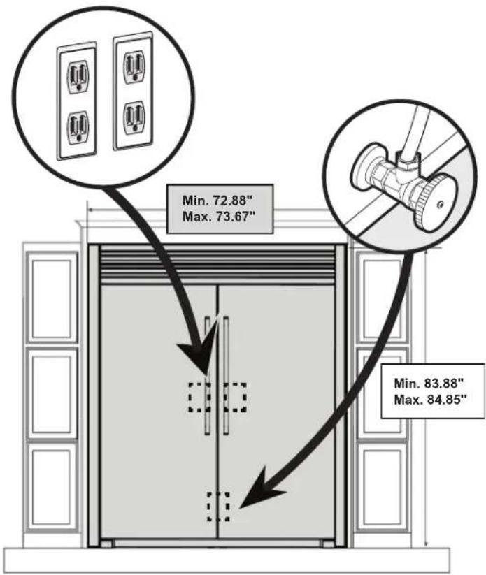
Trim Kit Finished Dimensions
Use these dimensions to layout adjoining cabinet door, drawers, and shelves.

IMPORTANT
Use two recessed duplex electrical outlets and a recessed water shutoff valve for a 24" minimum opening. For new construction, use a 25.25" cabinet depth dimension.
Safety: Always wear safety glasses when using power tools.
Tools Needed:
- Phillips™ Screwdriver -
^3/8 " & ^5/16 " Socket Wrench · Step Ladder
- Flathead Screwdriver · Power Drill and
5/16" Nut Driver Bit · Tape Measure
- Safety Glasses -
^3 /8" Nut Driver · Gloves
• Level
Before You Begin
- Be careful when unpacking components. Do not use sharp objects when removing packaging material. This may scratch the surface of trim components.
- Handle the metal trim pieces with extreme care as corners damage easily if dropped.
Instructions for Dual Installation Trim Kits:
TRMKTEZ2FL75 (Frigidaire)
TRMKTEZ2LV79 (Frigidaire)
TRMKTEZ2FL79 (Frigidaire)
TRMKTSS2FL79 (Electrolux)
TRMKTSS2LV84 (Electrolux)
Power and Water Line Connection
NOTE
Refer to the Use & Care Manual for power requirements and water supply hookup before proceeding. Find Service Kit TTFLTRICEKIT at ElectroluxAppliances.com for connecting the water line and filtering ice.
NOTE
If freezer unit is compatible with water filter kit, please see filtered water kit instructions.

CAUTION
Appliances are heavy. Installation requires two people.

IMPORTANT
Make sure there are two separate outlets for the freezer and the refrigerator.
Leveling System Installation
- a. Lay the refrigerator and freezer on their backs on packing material or a drop cloth to prevent damage and protect the floor.
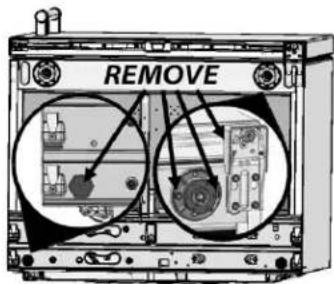
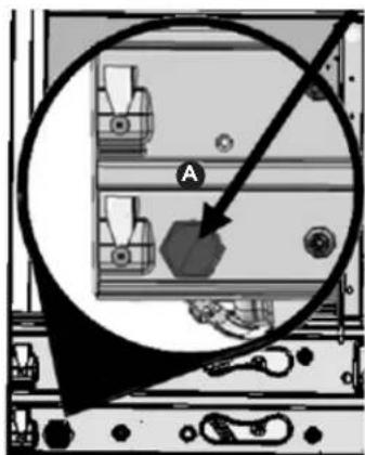
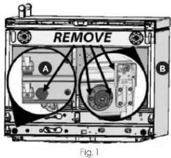
b. Remove all 4 rear leg levelers from the 2 units by unscrewing counterclockwise (Fig. 1A), and store them with your Product Literature.
natural_image
Diagram showing a mechanical assembly with a labeled component 'A' and an arrow pointing to it, enclosed in a circular frame (no readable text or symbols)c. Remove all 4 front leg levelers from the 2 units by unscrewing the outer peg and 2 bolts on each front leveler with a 5/16'' nut driver and store them with your Product Literature. Remove the hinge cover if it is installed (Fig 1B).
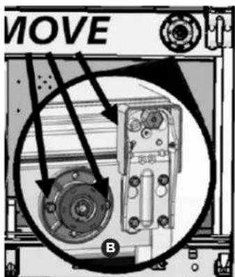
Fig.1
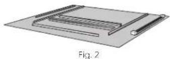
- Lay the parts out on a cleared area face down. Be sure to place a drop cloth over the floor to prevent scratching the trim kit and/or floor (Fig. 2).
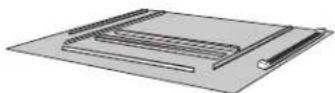
Fig 2
- a. Fit the first Leveler Assembly onto a refrigerator/freezer (Fig. 3).
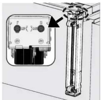
Fig. 3
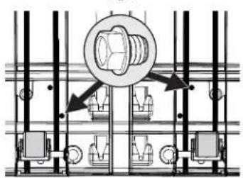
b. Using a 5H bolt and a power drill, fasten the bottom of the Leveler Assembly with a ^3/_6 hex drill bit in whichever hole overlaps the screw hole (Fig. 4).
Note: The rear of the bracket is contoured to slip over the metal compressor base. Driving the rear bolt first will ensure proper alignment of the lever assembly.
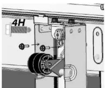
c. Using the 4H bolts from step 1, fasten the front of the Leveler Assembly to the refrigerator/freezer using a 5 / 16'' nut driver (Fig. 5).
natural_image
Technical diagram of a mechanical assembly with no visible text or symbolsFig. 4
natural_image
Mechanical assembly diagram showing a pulley system with labeled component '4H' (no readable text or symbols beyond label)Fig. 5
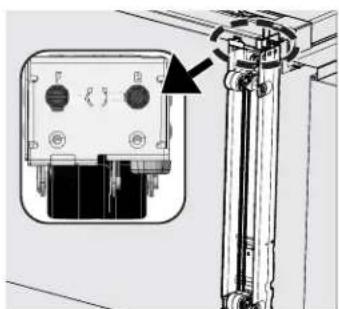
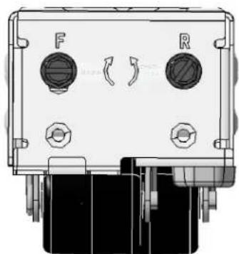
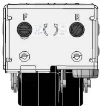
For steps 3b and 3c, if you require more space for nut driver clearance, rotate the bolt labeled F clockwise (Fig. 6) using a flathead screwdriver or a 3/8'' socket wrench.
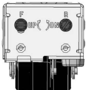
Fig. 6
d. Attach remaining 3 Leveler Assemblies as described in the previous 3 steps using the remaining six 4H bolts and the remaining three 5H bolts. With the unit(s) still on their backs, adjust all leveling wheels to approximately the orientation in Fig. 7.
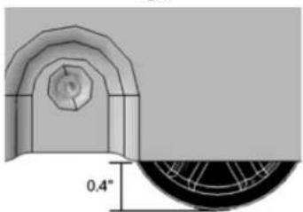
natural_image
Technical drawing of a mechanical component with an angular feature and circular base (no text or symbols)Fig. 7
Trim Kit Center Trim Support
- With the refrigerator still on its back, use a 516 " nut driver to remove two 4H bolts and fasten the 10H L-Bar (Fig. 8). Note: The short flange on L-Bar should be facing upward toward the top of the refrigerator.
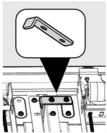
natural_image
Technical illustration of a mechanical component with a magnified view of a bracket (no text or symbols)Fig. 8
- Stand both units upright.

CAUTION
The cabinet is heavy. We recommend two people to lift or move the cabinet..
Pairing Kit Installation
Before cleaning your appliance, turn off power to your appliance by unplugging the power cord from the electrical outlet. Wipe down both sides of the refrigerator and the freezer.

NOTE
Never use CHLORIDE to clean stainless steel. Clean stainless-steel front and handles with non-abrasive soapy water and a dishcloth. Rinse with clean water and a soft cloth. Wipe stubborn spots with an ammonia-soaked paper towel, and rinse. Use a non-abrasive stainless-steel cleaner, such as Frigidaire ReadyClean™ Stainless Steel Cleaner found on Frigidaire.com. Always follow the manufacturer's instruction.

NOTE
Always, clean, wipe and dry with the grain to prevent scratching. Wash the rest of the cabinet with warm water and mild liquid detergent. Rinse well and wipe dry with a clean soft cloth.

CAUTION
Use gloves for the next step.
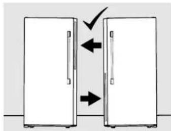
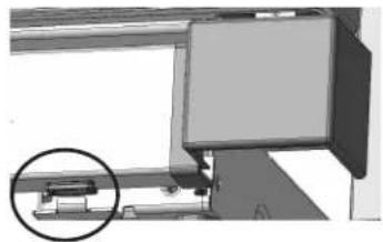
NOTE: Before removing the paper backing, align the heaters to ensure the wires exit toward the center and rear of refrigerator/freezer (as shown in Fig 9).
- Peel off the paper backing from the first heater.
- Adhere the first heater to the lower right side of the left-side unit (0.5" from the bottom and 0.5" from the back wall) so the harnesses come out at the top.
NOTE: Make sure you adhere the heater completely with no air pockets (Fig. 9A).
- Peel off the paper backing from the second heater.
- Adhere the second heater to the upper left side of the right-side unit (0.5" from the top and 0.5" from the back wall) so the harnesses come out at the bottom.
NOTE: Make sure you adhere the heater completely with no air pockets (Fig. 9B). For better adhesion remove the yellow label on the side of the cabinet.
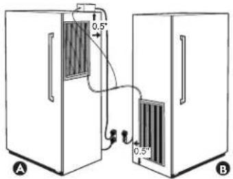
Fig. 9
NOTE: For the best results, please use the configurations of the heaters mentioned (Freezer-top right side and Refrigerator bottom left side).
Avoid:
- Both heaters on the Freezer
- Both heaters on the Refrigerator
- Both heaters on the top
- Both heaters on the bottom
-
Both heaters in the center
-
Plug in the connector of the two Heaters A into the Power Supply C (Fig. 10).
NOTE: You cannot feel the heater temperature as the pads barely heat up.
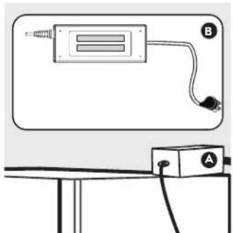
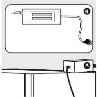
NOTE: Confirm the power supply fits into the cutout when placed on top of the unit. Also confirm the power supply reaches the power outlet when placed on top of the unit (Fig. 11A). The extra wire length is provided to accommodate receptacle location.
11. Apply the 2 strips of double-sided tape to the power supply and adhere the power supply on top of the unit (Fig. 11B).
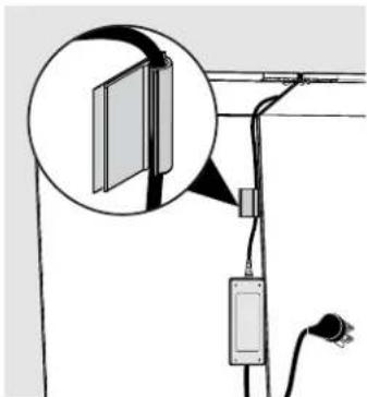
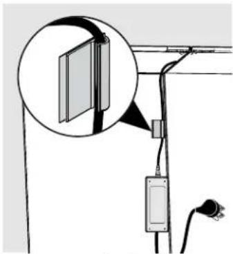
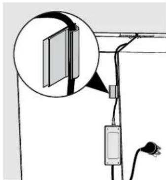
12. If the power supply cannot be placed on top of the unit, adhere it vertically on the back wall of the unit and make sure the connection of the 3-prong connector to the power supply is facing down (Fig. 12).
natural_image
Diagram showing two doors with arrows indicating movement or force, no text or symbols present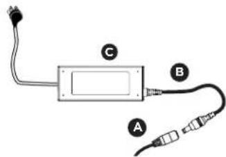
Fig. 10
natural_image
Simple line drawing of a device setup with labeled components A and B, no text or symbols present.Fig.11
natural_image
Diagram showing a cable or cable connector with a magnified inset of a panel mounted on a wire, connected to a plug (no text or symbols visible)Fig. 12
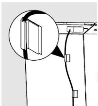
- Use the clips provided to hold the excess power cords to the back of the units such that all wires are away from the floor (Fig. 13).
NOTE: Make sure the harnesses and cables are cleared off the floor before the units are pushed back in place. This will prevent any damage to the wires.
NOTE: The location of clips shown is an example.
- Plug the power supply into the main outlet before pushing the units into the final position.
natural_image
Diagram of a device with a magnified inset showing a screen mounted on a panel, connected to wires (no text or symbols present)Fig. 13
Trim Kit Tie Bar Installation

IMPORTANT
-
Before proceeding with trim installation, make sure both refrigerator and freezer are leveled front to back and side to side.
• Make sure all 8 wheels are touching the floor. -
Having the refrigerator/freezer standing side by side 12 " apart, fasten a 9H bracket to the front of the Levelers (Fig. 14), keeping the left-side 8H screws loose.
Hand tighten only!
NOTE: One side of the bracket is slotted for fine adjustments in step 18c.
-
Attach the other 9H bracket to the rear levelers (Fig. 15), keeping the right screws loose. Hand tighten only!
-
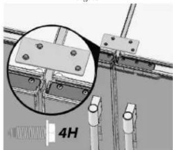
Attach the 1H top tie bar (Fig. 16), keeping the 2 left 4H bolts loose.
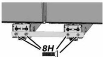
Fig.14

Fig.15
natural_image
Mechanical assembly diagram showing a bracket with mounting holes and a 4H label (no readable text or symbols)Fig.16
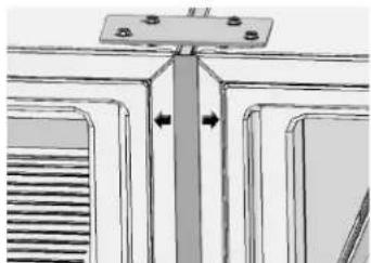
- a. Open the doors and place the middle trim in between the 2 units.
b. Adjust the proximity of the units as needed to centralize the middle trim. Start by fastening the screws on top 1H bracket in order to evenly space the Center Trim (Fig. 17).
natural_image
Technical line drawing of a mechanical assembly with no visible text or symbolsFig.17
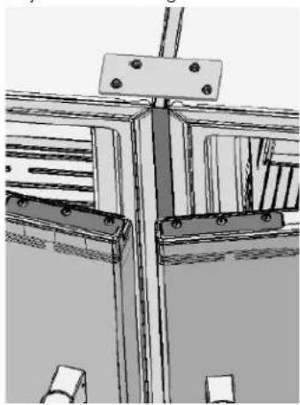
c. Fasten the four 8H screws (Fig. 14 and 15) through 2 front and back 9H brackets. You may need several adjustments for the center trim to be consistently flush and centered to the units.
NOTE: Before continuing, ensure doors close without interference and remain parallel. Adjusting the height of the wheels can help remedy door alignment issues. Refer to INSTALLATION in the Use & Care Manual to adjust the door height.
natural_image
Technical line drawing of a mechanical assembly with no visible text or symbols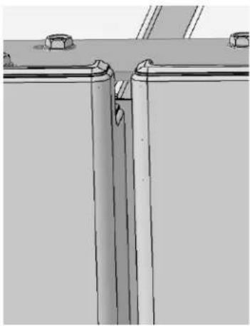
natural_image
Pure technical line drawing of a structural joint or bracket (no text or symbols)Fig. 18

NOTE
Before proceeding plug in units and verify they are functioning properly.

NOTE
Some cabinet substrates may require pre-drilling holes using a^1/_8 (3 mm) diameter drill bit.
Electrolux TRMKTSS2LV84 Side Trim Attachment Setup (some models)
- Using eight 3H screws and a power drill, attach the two Side Trim Attachment brackets to the front left and right cabinet cut-out edges with the brackets touching the floor (Fig. 19). Ensure the rectangular slots extend over the cabinet edge.
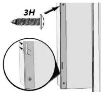
Fig. 19
Side Trim Attachment Setup For:
TRMKTEZ2FL75 (Frigidaire)
TRMKTEZ2LV79 (Frigidaire)
TRMKTEZ2FL79 (Frigidaire)
TRMKTSS2FL79 (Electrolux)
-
Depending on which long screw you received (6H or 7H), screw a long screw into the lower left (Fig. 20A) of the front wall cabinet, close to the location shown in Fig. 20B.
-
Repeat step 20 for the right side of the wall cabinet using the other 6H/7H screw.
NOTE: The depth of the screw will vary depending on the cabinet cutout final dimensions. We recommend you leave approximately 12 " of screw extending away from the cabinet wall.
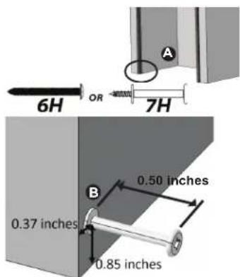
Fig. 20
Top Trim Attachment

NOTE
You will need a step ladder to install top trim components.
- a. Remove the front outer hinge screws, common on both sides of the dual installation, as well as the front two 4H screws that fasten the 1H Tie Bar (Fig. 21).
b. Roll the dual installation into the cabinet, roughly 14 of the way in, ensuring the product is centered in the cabinet cutout.
c. Install the top trim by fastening four 4H screws along the base of the trim with a ^5/^16 " socket wrench (Fig. 22).
- a. Slide the dual installation into place, and make sure it is center inside the cabinets.
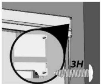
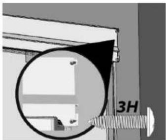
b. Drill 18 " pilot holes and fasten two 3H screws on the right side of the Top Trim (one screw per side for Collared top trim) with a Phillips screwdriver to the cabinets (Fig. 23).
c. Repeat for the left side.
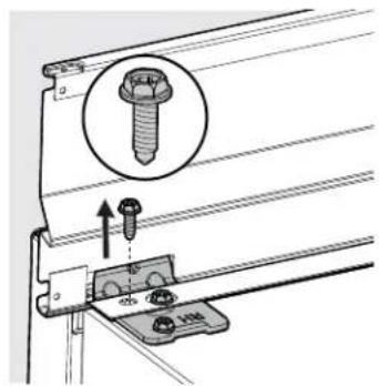
Fig. 21
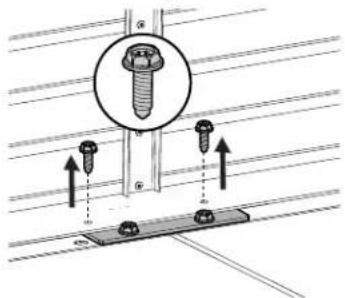
Fig. 22
natural_image
Technical diagram showing a mechanical assembly with a magnified inset highlighting a 3H bolt detail (no text or symbols present)Fig. 23
Electrolux TRMKTSS2LV84 Side Trim Installation
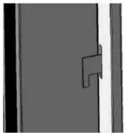
- a. Slide the left Side Trim into place by carefully guiding the Side Trim Attachment slots. Fig. 25 shows an inside view.
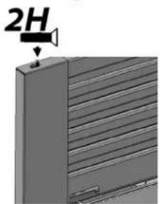
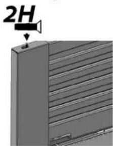
b. Fasten 2H screws to the top trim (Fig. 26) and repeat for the right hand side. Hand lighten only!
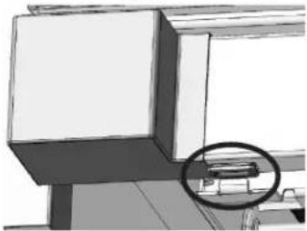
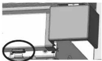
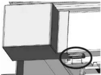
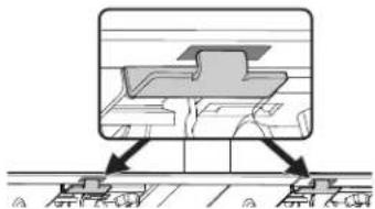
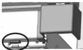
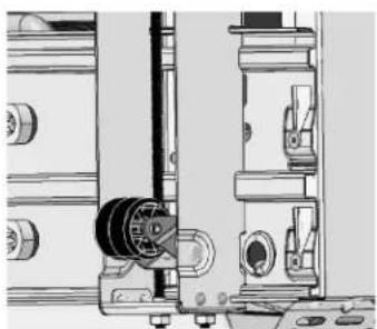
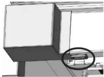
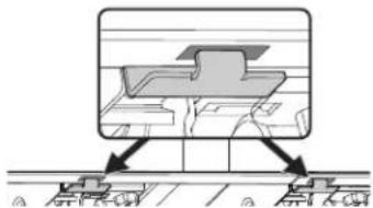
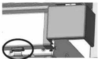
- a. Carefully place the Toe Kick slots over the 4 Leveler Assembly Tabs. The first Leveler Assembly tab is circled in Fig. 27, the second and third tabs are circled in Fig. 28, and the fourth tab is circled in Fig. 29.
b. Adjust the Toe kick until the magnets are engaged to the Leveler Assembly and the Toe Kick is resting vertically in place.
natural_image
Simple line drawing of a door with a handle and vertical panel (no text or symbols)Fig. 25
natural_image
3D diagram of a vertical panel with horizontal ridges and a labeled component '2H' (no text or symbols beyond the label)Fig. 26
natural_image
3D mechanical assembly diagram showing a bracket with a magnified inset of a component (no text or symbols visible)Fig. 27

natural_image
Technical diagram showing mechanical assembly with no visible text or symbolsFig. 28
natural_image
Mechanical assembly diagram showing a component with a magnified inset (no text or symbols visible)Fig. 29
Side Trim Installation For:
TRMKTEZ2FL75 (Frigidaire)
TRMKTEZ2LV79 (Frigidaire)
TRMKTEZ2FL79 (Frigidaire)
TRMKTSS2FL79 (Electrolux)
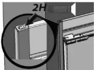
- a. Place side trims in position by dropping them over the placement screw as seen in Fig. 21 and fitting over the top trim (Fig. 24).
natural_image
Diagram showing a 2H window with an arrow pointing to the door panel, no text or symbols presentFig. 24
Instructions for Single Installation Trim Kits:
TRMKTEZ1FL79 (Frigidaire)
TRMKTSS1LV84 (Electrolux)

CAUTION
Appliances are heavy. Installation requires two people.
Leveling System Installation
-
a. Lay the unit on its back on packing material or a drop cloth to prevent damage and protect the floor.
b. Remove both rear leg levelers by unscrewing counterclockwise (Fig. 1A), and store them with your Product Literature.
c. Remove both front leg levelers by unscrewing the outer peg and 2 bolts on each front leveler with a ^5/_16 " nut driver. Remove the hinge cover if it is installed (Fig 1B), and store them with your Product Literature. -
Lay the parts out on a cleared area face down. Be sure to place a drop cloth over the floor to prevent scratching the trim kit and/or floor (Fig. 2).
-
a. Fit the first Leveler Assembly onto a refrigerator/freezer (Fig. 3).
natural_image
Diagram of a mechanical device with a flat base and cylindrical component, labeled Fig. 2 (no text or symbols on the diagram itself)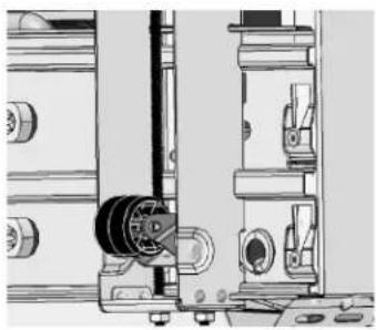
natural_image
Mechanical assembly diagram showing internal components and mounting holes (no text or labels)Fig. 3
b. Using a 5H bolt and a power drill, fasten the bottom of the Leyeler Assembly with a 3/8'' hex drill bit in whichever hole overlaps the screw hole (Fig. 4). Note: The rear of the bracket is contoured to slip over the metal compressor base. Driving the rear bolt first will ensure proper alignment of the lever assembly.
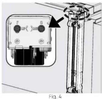
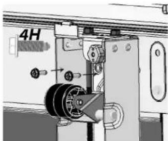
c Using the 4H bolts from step 1, fasten the front of the Leveler Assembly to the refrigerator/freezer using a ^5/16 " nut driver (Fig. 5). For steps 3b and 3c, if you need more space for the nut driver clearance, rotate the bolt labeled "F" clockwise (Fig. 6) using a flathead screwdriver or a ^3/8 " socket wrench.
natural_image
Mechanical assembly diagram showing a pulley mechanism with labeled part '4H' (no readable text or symbols beyond label)Fig. 5
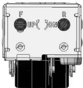
Fig. 6
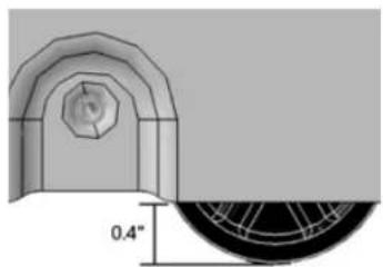
d. Attach the remaining Leveler Assembly as described in the previous 3 steps. With the unit still on its back, adjust all leveling wheels to approximately the orientation in Fig. 7.
natural_image
Technical drawing of a mechanical component with an angular dimension labeled 0.4" (no text or symbols beyond the dimension)Fig. 7
Leveling the Unit
- a. Tilt the unit upright.
b. Place the unit into the cabinet space, or as close to the final position as possible (do not hook up power or water yet). This step is important to accurately level the unit prior to further installs.
c. Use a flat head screw
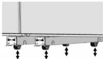
driver or a ^3/_8 " socket wrench to adjust the front bolts of the Leveler Assemblies (Fig. 8). Raise or lower the front and back wheels as needed until the unit rests properly in the cabinet space.
d. Once the Leveler Assemblies have been checked, roll out the unit in front of the cabinetry for accessibility.
natural_image
Mechanical assembly diagram showing a rail support frame with four wheels and mounting brackets (no text or symbols)Fig. 8
NOTE
Some cabinet substrates may require pre-drilling holes using a^1/s'' (3 mm) diameter drill bit.
Electrolux TRMKTSS1LV84 Side Trim Attachment Setup
- Using eight 3H screws and a power drill, attach the 2 Side Trim Attachment brackets to the front left and right cabinet cutout edges with the brackets touching the floor (Fig. 9). Ensure the rectangular slots extend over the cabinet edge.
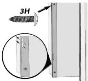
Fig. 8
Frigidaire TRMKTEZ1FL79 Side Trim Attachment Setup
- Depending on which long screw you received (6H or 7H) screw a long screw in the lower left area (Fig. 9A) of the front cabinet space, approximately in the location described in Fig. 9B.
- Repeat step 6 for the right side of the cabinet using the other 6H/7H screw.
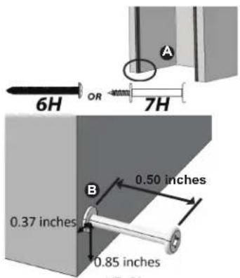
Fig. 9
Power and Water Line Connection
Note: Refer to the Use & Care Manual for power requirements and water supply hookup before proceeding. Find Service Kit TTFLTRICEKIT at ElectroluxAppliances.com for connecting the water line and filtering ice.
Top Trim Attachment
NOTE
You will need a step ladder to install top trim components.
- a. Remove the front outer screw from the top hinge (Fig. 10) using a 5/16'' socket driver or wrench and save for later. Locate bracket 1H and place it on the top of the unit to be used on Step 8d.
b. Roll the unit into the cabinet roughly 34 of the way in, ensuring the product is centered in the cabinet cutout.
c. Choose the top trim according to which side the door hinge is on (Fig. 11). You do not need the other Top Trim for the installation.
d. Install the Top Trim by fastening two 4H screws along the base of the trim with a ^5/_16 " socket wrench (Fig. 12). Screw through the 1H bracket in step 8a to properly level the Top Trim.
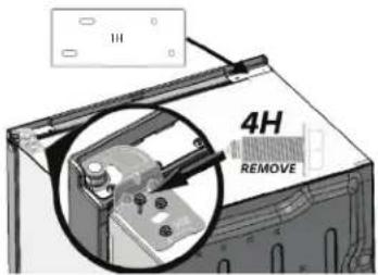
Fig. 10
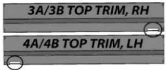
Fig. 11
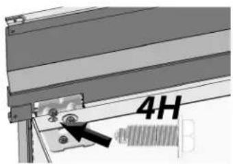
Fig. 12
- a. Slide the unit into place, and ensure the dual installation is centered.
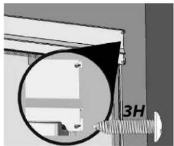
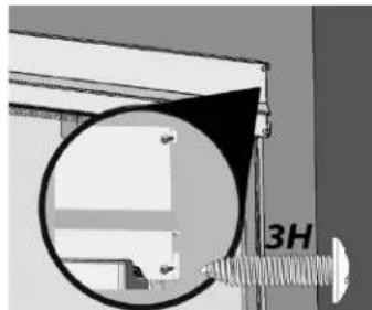
b. Drill 18 " pilot holes and fasten two 3H screws on the right side of the Top Trim with a Phillips screwdriver to cabinets (Fig. 13).
c. Repeat for the left side.
natural_image
Close-up of a mechanical component with a magnified inset showing a circular feature and a 3H bolt (no text or symbols)Fig. 13
Frigidaire TRMKTEZ1FL79 Side Trim Installation
- a. Place the Side Trims in position by dropping them over the placement screw as seen in Fig. 9 and fitting them over the Top Trim (Fig. 14). b. Fasten a 2H screw to each side of the Top Trim (Fig. 14). Hand tighten only!
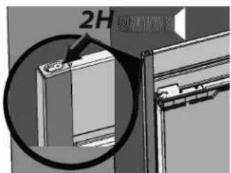
Fig. 14
Electrolux TRMKTSS1LV84 Side Trim Installation
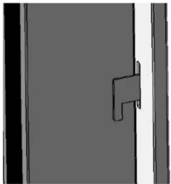
- a. Slide the left Side Trim into place by carefully guiding the Side Trim hooks through the Side Trim Attachment slots. Fig. 15 shows an inside view.
natural_image
Simple line drawing of a door with a handle and vertical panel (no text or symbols)Fig. 15
b. Fasten 2H screws to the Top Trim (Fig. 16) and repeat for the right hand side. Hand tighten only!
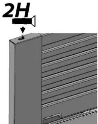
Fig. 16
- a. Choose which Toe Kick to place below the unit based on which side the door hinge is on (Fig. 17). You do not need the other Toe Kick.
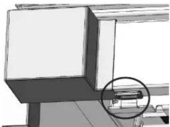
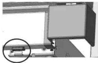
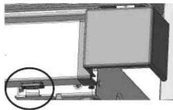
b. Carefully place the Tow Kick over the 2 Leveler Assembly Slots. The first Leveler Assembly slot is circled in Fig. 18, and the second Leveler Assembly slot is circled in Fig. 19.
c. Adjust the Toe Kick until the magnets are engaged to the Leveler Assembly bolts and the Toe Kick is resting vertically in place.
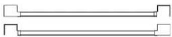
Fig 17
natural_image
3D mechanical assembly diagram showing a bracket and mounting base with a magnified inset (no text or symbols)Fig 18
natural_image
3D mechanical assembly diagram showing a mounted device with a magnified inset (no text or symbols visible)Fig. 19
Note: Refer to the Use & Care Manual to adjust the door height if needed.
Paquete de tornilleria A20841303
| ARTÍCULO | NÚMERO DE PIEZA | DESCRIPCIÓN | CANT. |
| 1H | A18695801 | Barra de sujeción, superior | 1 |
| 2H | 297142600 | Tornillo, cabeza plana, n.° 8-32 | 2 |
| 3H | 050149 Tornillo, redondo, n.° 8-18 | 4 | |
| 4H | A16955502 | Perno, M5 x 16 | 6 |
| 5H | A21188301 | Perno, 1/4-20 | 2 |
| 6H, 7H | A20706101 | Tornillo de la base de la moldura | 1 |


natural_image
Diagram showing a mechanical assembly with a labeled component 'A' and an arrow pointing to it, enclosed in a circular frame (no readable text or symbols)natural_image
Technical diagram of an electrical enclosure with a mechanical arm attachment (no text or symbols visible)Fig. 3
natural_image
Technical diagram of a mechanical assembly with no visible text or symbolsFig. 4
natural_image
Mechanical assembly diagram showing a pulley mechanism with labeled part '4H' (no readable text or symbols beyond label)Fig. 5
natural_image
Technical drawing of a mechanical component with an arched top and circular base, showing a 0.4" dimension line (no text or symbols beyond the dimension label)Fig. 7
Soporte de la moldura central del kit de molduras
natural_image
Technical diagram showing a mechanical component with a highlighted section and a downward arrow pointing to it (no text or symbols present)Fig. 8
natural_image
Diagram of two doors with arrows indicating movement or force, no text or symbols present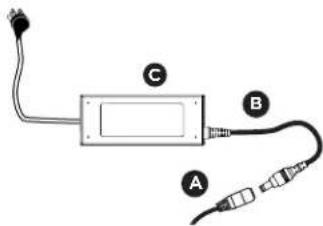
Fig. 10
natural_image
Simple line drawing of a device with labeled components A and B, no text or symbols presentFig. 11
natural_image
Diagram of a cable or electrical connector with a magnified inset showing a panel detail (no text or symbols)Fig. 12
natural_image
Diagram of a device with a magnified inset showing a screen mounted on a panel, connected to wires (no text or symbols present)Fig.13
natural_image
Mechanical assembly diagram showing a bracket with mounting holes and a 4H label (no readable text or symbols)Fig.16
natural_image
Pure mechanical diagram showing a vertical rod inserted into a bracket, with no text or symbols present.Fig.17
natural_image
Technical line drawing of a mechanical assembly with bolts and brackets (no text or symbols)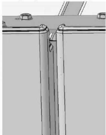
natural_image
Technical line drawing of a metal bracket with bolts and a central vertical seam (no text or symbols)Fig. 18

NOTA
natural_image
Technical diagram of a mechanical assembly with a magnified inset showing a bolt detail (no text or symbols)Fig. 21
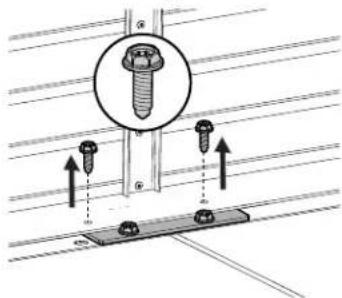
Fig. 22
natural_image
Technical diagram showing a mechanical assembly with a magnified inset highlighting a 3H bolt detail (no text or symbols present)Fig. 23
natural_image
Simple line drawing of a door with a handle and vertical line (no text or symbols)Fig. 25
natural_image
3D rendering of a building facade with horizontal slats and a 2H indicator (no text or symbols on the structure itself)Fig. 26
natural_image
3D mechanical assembly diagram showing a bracket with a magnified inset of a component (no text or symbols visible)Fig. 27
natural_image
Technical diagram showing mechanical assembly with arrows indicating direction (no text or symbols)Fig. 28
natural_image
Mechanical assembly diagram showing a mounted device with a magnified inset (no text or symbols visible)Fig. 29
Fig.1

Fig. 2
natural_image
Mechanical assembly diagram showing internal components and mounting brackets (no text or labels)Fig. 3
natural_image
Technical diagram of a mechanical device with an open panel and bracket (no text or symbols visible)Fig. 4
natural_image
Mechanical assembly diagram showing a pulley mechanism with labeled part '4H' (no readable text or symbols beyond label)Fig. 5
natural_image
Technical diagram of a mechanical device with labeled ports (F and R) and internal components, no readable text or symbols beyond labelsFig. 6
natural_image
Technical drawing of a mechanical component with an angular dimension labeled 0.4" (no text or symbols beyond the dimension)Fig. 7
natural_image
Mechanical assembly diagram showing a frame with wheels and mounting brackets (no text or symbols)Fig. 8
Fig.10
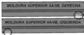
Fig. 11
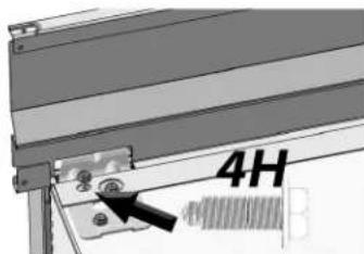
Fig. 12
natural_image
Close-up of a mechanical component with a magnified circular detail and a 3H bolt, no visible text or symbols.Fig. 13
natural_image
Simple line drawing of a door with a handle and vertical panel (no text or symbols)Fig. 15
natural_image
3D mechanical assembly diagram showing a bracket and housing with a magnified inset (no text or symbols)Fig 18
natural_image
Mechanical assembly diagram showing a monitor mounted on a bracket with a magnified inset detail (no text or symbols visible)Fig. 19
| Ensemble de quincaillerie A20841303 | |||
| ARTICLE | NUMÉRO DE PIÈCE | DESCRIPTION | QTÉ |
| 1H | A18695801 | Barre d'attache, dessus | 1 |
| 2H | 297142600 | Vis à tête plate, no 8-32 | 2 |
| 3H | 050149 | Vis tête ronde, no 8-18 | 4 |
| 4H | A16955502 | Boulon, M5 x 16 | 6 |
| 5H | A21188301 | Boulon, 1⁄4-20 | 2 |
| 6H, 7H | A20706101 | Vis de base de la garniture | 1 |
natural_image
Diagram showing a device with labeled components and an arrow pointing to a hexagonal component (no readable text or symbols)Fig. 3
natural_image
Technical diagram of a mechanical assembly with no visible text or symbolsFig. 4
Trousse de garniture support de garniture centrale
natural_image
Technical diagram showing a bracket component with a magnified inset view (no text or symbols)Fig. 8
natural_image
Mechanical assembly diagram showing a motor with gears and pulleys (no text or symbols)Fig. 5
Fig. 6
natural_image
Technical drawing of a mechanical component with an angular feature and circular base (no text or symbols)Fig. 7
natural_image
Diagram of two doors with arrows indicating movement or force, no text or symbols present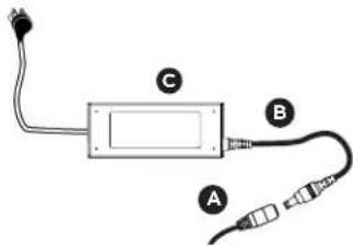
Fig. 10
natural_image
Simple line drawing of a rectangular device with two horizontal bars and a terminal plug, labeled B (no text or symbols)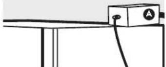
natural_image
Simple line drawing of a table with a box labeled 'A' and a cable, no text or symbols present.Fig. 11
natural_image
Diagram showing a cable or cable connector with a magnified inset of a panel mounted on a wall, no text or symbols present.Fig.12
natural_image
Diagram showing a device with a magnified inset of a screen and cable, no text or symbols presentFig.13
natural_image
Mechanical assembly diagram showing a bracket with mounting holes and a 4H label (no readable text or symbols)Fig.16
natural_image
Technical diagram showing a structural joint with arrows indicating direction (no text or symbols present)Fig.17
natural_image
Technical line drawing of a mechanical assembly with no visible text or symbols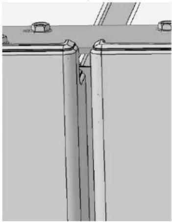
natural_image
Technical line drawing of a metal bracket with bolts and mounting feet (no text or symbols)Fig. 18

REMARQUE
Fig. 21
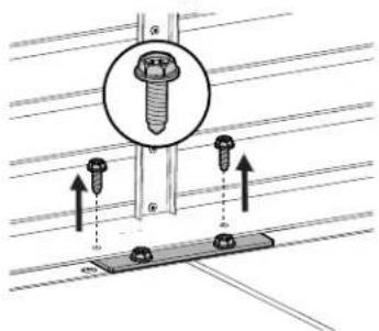
Fig. 22
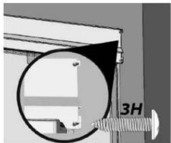
natural_image
Close-up of a mechanical component with a magnified inset showing a 3H bolt detail (no text or symbols)Fig. 23
Installation de la garniture latérale Electrolux TRMKTSS2LV84
natural_image
Simple line drawing of a door with a handle and vertical panel (no text or symbols)Fig. 25
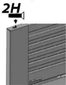
natural_image
3D rendering of a building facade with horizontal slats and a 2H indicator (no text or symbols on the structure itself)Fig. 26
natural_image
3D mechanical assembly diagram showing a bracket with a magnified inset of a component (no text or symbols visible)Fig. 27
natural_image
Technical diagram showing mechanical assembly with arrows indicating alignment or force direction (no text or symbols)Fig. 28
natural_image
Mechanical assembly diagram showing a mounted device with a magnified inset (no text or symbols visible)Fig. 29
natural_image
Diagram showing a 2H window with a magnified inset highlighting the window (no text or symbols present)Fig. 24
natural_image
Technical line drawing of a mechanical assembly with gears and housing (no text or symbols)Fig. 3
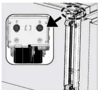
Fig. 4
natural_image
Mechanical assembly diagram showing a pulley mechanism with labeled part '4H' (no readable text or symbols beyond label)Fig. 5
natural_image
Technical diagram of a mechanical device with labeled ports (F and R) and internal components, no readable text or symbols beyond labelsFig. 6
natural_image
Technical drawing of a mechanical component with an angular dimension labeled 0.4" (no text or symbols beyond the dimension)Fig. 7
natural_image
Mechanical assembly diagram showing a frame with wheels and mounting brackets (no text or symbols)Fig. 8
natural_image
Close-up of a mechanical component with a magnified circular detail and a 3H bolt, no visible text or symbolsFig. 13
natural_image
Simple line drawing of a door with a handle and vertical panel (no text or symbols)Fig. 15
natural_image
3D mechanical assembly diagram showing a bracket and housing with a magnified inset (no text or symbols)Fig 18
natural_image
Mechanical assembly diagram showing a monitor mounted on a bracket with a magnified inset detail (no text or symbols visible)- Single-Door All Refrigerator and All Freezer Trim Kit Installation
- Single Trim Kits (79" & 84" Tall Cabinet Cutouts)
- IMPORTANT
- Cabinet Cutout Dimensions
- Trim Kit Finished Dimensions
- Dual Trim Kits (75" & 79" Tall Cabinet Cutouts)
- NOTE
- Dual Trim Kits (84" Tall Cabinet Cutouts)
- TRMKTSS2LV84 (Electrolux)
- Safety: Always wear safety glasses when using power tools.
- Tools Needed:
- Before You Begin
- Instructions for Dual Installation Trim Kits:
- Power and Water Line Connection
- CAUTION
- Leveling System Installation
- Trim Kit Center Trim Support
- Pairing Kit Installation
- Avoid:
- Trim Kit Tie Bar Installation
- Hand tighten only!
- Electrolux TRMKTSS2LV84 Side Trim Attachment Setup (some models)
- Side Trim Attachment Setup For:
- Top Trim Attachment
- Electrolux TRMKTSS2LV84 Side Trim Installation
- Side Trim Installation For:
- Instructions for Single Installation Trim Kits:
- Leveling the Unit
- Electrolux TRMKTSS1LV84 Side Trim Attachment Setup
- Frigidaire TRMKTEZ1FL79 Side Trim Attachment Setup
- Frigidaire TRMKTEZ1FL79 Side Trim Installation
- Electrolux TRMKTSS1LV84 Side Trim Installation
- Soporte de la moldura central del kit de molduras
- NOTA
- Trousse de garniture support de garniture centrale
- REMARQUE
- Installation de la garniture latérale Electrolux TRMKTSS2LV84
Brand : FRIGIDAIRE
Model : FPRU19F8WSS
Category : Refrigerator